JP5033233B2 - Mowing harvester - Google Patents
Mowing harvester Download PDFInfo
- Publication number
- JP5033233B2 JP5033233B2 JP2010271417A JP2010271417A JP5033233B2 JP 5033233 B2 JP5033233 B2 JP 5033233B2 JP 2010271417 A JP2010271417 A JP 2010271417A JP 2010271417 A JP2010271417 A JP 2010271417A JP 5033233 B2 JP5033233 B2 JP 5033233B2
- Authority
- JP
- Japan
- Prior art keywords
- light
- bulbs
- valves
- cover
- transparent cover
- Prior art date
- Legal status (The legal status is an assumption and is not a legal conclusion. Google has not performed a legal analysis and makes no representation as to the accuracy of the status listed.)
- Active
Links
Images


Description
本発明は、刈取収穫機に備えられるライトの構造に関する。 The present invention relates to a light structure provided in a harvesting and harvesting machine.
コンバイン等の刈取収穫機では夕暮れ時や夜間でも刈取作業を行うことが増えてきており、例えば特許文献1に開示されているように、刈取部にライト(特許文献1の第1,2,3図の1)を備えたものがある。 With harvesting machines such as combine harvesters, there is an increasing number of harvesting operations at dusk and at night. For example, as disclosed in Patent Literature 1, a light is provided in the harvesting portion (first, second, third in Patent Literature 1). Some have 1) in the figure.
コンバイン等の刈取収穫機において、刈取部は比較的横幅が大きなものとなっている。これにより、刈取部から比較的広い範囲に亘って照射しようとすると、刈取部に多数のライトを備えなければならない。
本発明はコンバイン等の刈取収穫機において、刈取部にライトを備える場合、ライトの数を抑えながら、刈取部から比較的広い範囲に亘って照射することができるように構成することを目的としている。
In a harvesting and harvesting machine such as a combine, the harvesting part has a relatively large width. Thereby, when it is going to irradiate over a comparatively wide range from a cutting part, a lot of lights must be provided in a cutting part.
An object of the present invention is to provide a harvester such as a combine harvester that can irradiate a relatively wide range from the harvesting unit while suppressing the number of lights when the harvesting unit includes a light. .
(構成)
本発明の第1特徴は、刈取収穫機において次のように構成することにある。
機体の前部に刈取部を備え、前記刈取部の最も右側に位置する引き起し装置の上部の横外側に、側面視で引き起し装置の上部と重複する状態で、縦長の右のライトを設けると共に、前記刈取部の最も左側に位置する引き起し装置の上部の横外側に、側面視で引き起し装置の上部と重複する状態で、縦長の左のライトを設け、
前記右のライトを、複数のバルブと、複数のバルブの各々に備えられた複数のリフレクタと、複数のバルブ及び複数のリフレクタを覆う縦長の透明カバーとを備えて構成すると共に、前記左のライトを、複数のバルブと、複数のバルブの各々に備えられた複数のリフレクタと、複数のバルブ及び複数のリフレクタを覆う縦長の透明カバーとを備えて構成し、
前記右のライトにおいて、複数のバルブのうちの一つのバルブと、複数のバルブのうちの別のバルブとを、透明カバーの内部に上下方向に位置ずれした状態で配備すると共に、前記左のライトにおいて、複数のバルブのうちの一つのバルブと、複数のバルブのうちの別のバルブとを、透明カバーの内部に上下方向に位置ずれした状態で配備し、
前記右のライトの透明カバーを、正面視で縦長のカバー前面と、側面視で縦長のカバー横面とで構成すると共に、前記左のライトの透明カバーを、正面視で縦長のカバー前面と、側面視で縦長のカバー横面とで構成し、
前記右のライトにおいて、複数のバルブのうちの一つのバルブの光の向きと、複数のバルブのうちの別のバルブの光の向きとが異なるものとなるように、一つのバルブの向き又は別のバルブの向き又はリフレクタの向きを設定すると共に、前記左のライトにおいて、複数のバルブのうちの一つのバルブの光の向きと、複数のバルブのうちの別のバルブの光の向きとが異なるものとなるように、一つのバルブの向き又は別のバルブの向き又はリフレクタの向きを設定している。
(Constitution)
The first feature of the present invention resides in the following configuration in a harvesting harvester.
A vertical right light with a cutting part at the front of the fuselage and on the lateral outer side of the upper part of the pulling device located on the rightmost side of the cutting part, overlapping with the upper part of the lifting device in side view. And a vertically long left light is provided on the lateral outer side of the upper part of the pulling device located on the leftmost side of the mowing part, in a state overlapping with the upper part of the pulling device in a side view,
The right light, and a plurality of valves, as well as constructed to include a plurality of reflectors provided to each of the multiple valves, and a transparent cover of the longitudinal covering the plurality of valves and a plurality of reflectors, the left The light comprises a plurality of bulbs, a plurality of reflectors provided in each of the plurality of bulbs, and a vertically long transparent cover that covers the plurality of bulbs and the plurality of reflectors,
In the right light, one valve of the plurality of valves and another valve of the plurality of valves are disposed in the transparent cover in a vertically displaced state, and the left light In the above, one valve of the plurality of valves and another valve of the plurality of valves are disposed in the transparent cover in a state of being vertically displaced,
The transparent cover of the right light is composed of a vertically long cover front in a front view and a vertically long cover horizontal in a side view, and the transparent cover of the left light is a vertically long cover front in a front view. It consists of a vertically long cover side view in side view,
In the right light, the light direction of one bulb of the plurality of bulbs and the light direction of another bulb of the plurality of bulbs are different from each other. In the left light, the light direction of one of the plurality of bulbs is different from the light direction of another of the plurality of bulbs. The direction of one valve, the direction of another valve, or the direction of the reflector is set so as to be the same.
(作用)
刈取部にライトを備える場合、バルブの光が一つの向きにしか設定されていないライトでは、刈取部から比較的広い範囲に亘って照射しようとすると、刈取部の各部に多数のライトを備える必要がある。
(Function)
When the light is provided in the cutting part, if the light of the bulb is set in only one direction, if it is intended to irradiate over a relatively wide range from the cutting part, it is necessary to provide a large number of lights in each part of the cutting part There is.
本発明の第1特徴によると、刈取部にライトを備えた場合、一つのライトから異なる向きにバルブの光が照射されるので、一つのライトの照射範囲が広いものとなる。このように本発明の第1特徴によると、一つのライトの照射範囲が広いものとなるので、刈取部の各部に多数のライトを備えなくても、刈取部の適切な位置に二つのライトを備えることにより、刈取部から比較的広い範囲に亘って照射することができる。 According to a first feature of the present invention, when a write to the reaper, the different orientations from one of the light than light valve is illuminated, it becomes a wide irradiation range of one light. Thus, according to a first feature of the present invention, since as a wide irradiation range of one light, without a large number of lights to each part of the reaper, two in position reaper By providing this light, it is possible to irradiate over a relatively wide range from the cutting part.
本発明の第1特徴によると、刈取部の各部に多数のライトを備える必要がないので、多数のライトへの配線を刈取部の各部に配置する必要が少なくなる。このように本発明の第1特徴によると、多数のライトへの配線を刈取部の各部に配置する必要が少なくなるので、刈取収穫機の生産時においてライトへの配線の取付作業が少なくなるのであり、ライトへの配線の生産後のメンテナンス作業も行い易くなる。 According to a first feature of the present invention, it is not necessary to provide a large number of lights to each part of the reaper, it must be disposed in the respective sections of the reaper wiring to a large number of light decreases. Thus, according to a first feature of the present invention, since the need to place the respective parts of the reaper wiring to a large number of light decreases, less installation work wiring to light during the production of the reaper harvester As a result, the maintenance work after the production of the wiring to the light is facilitated.
(発明の効果)
本発明の第1特徴によると、刈取収穫機において刈取部の各部に多数のライトを備えなくても、刈取部の適切な位置に二つのライトを備えることにより、刈取部から比較的広い範囲に亘って照射することができるようになって、機体の運転部から広い範囲に亘って見易くなり、特に夕暮れ時や夜間での刈取作業の作業性及び路上での走行性を向上させることができた。
本発明の第1特徴によると、刈取収穫機の生産時においてライトへの配線の取付作業が少なくなる点により、生産コストの低減を図ることができるのであり、ライトへの配線の生産後のメンテナンス作業が行い易くなる点により、メンテナンス作業の作業性を向上させることができた。
(Effect of the invention)
According to a first feature of the present invention, even without a large number of lights to each part of the reaper in reaper harvester, by providing two light in position reaper, relatively from the reaper It is possible to irradiate over a wide range, and it is easy to see over a wide range from the operating part of the aircraft, especially improving the workability of cutting work at dusk and night and the running performance on the road I was able to.
According to the first feature of the present invention, it is possible to reduce the production cost by reducing the work of attaching the wiring to the light during the production of the harvesting harvester, and the maintenance after the production of the wiring to the light is achieved. The workability of the maintenance work can be improved due to the ease of work.
本発明の第2特徴は、本発明の第1特徴の刈取収穫機において次のように構成することにある。The second feature of the present invention resides in the following configuration in the harvesting and harvesting machine of the first feature of the present invention.
前記右のライトの透明カバーを、そのカバー横面の下部が側面視で下端側ほど細くなり、そのカバー横面の上部が側面視で上端側ほど細くなる形状に形成すると共に、前記左のライトの透明カバーを、そのカバー横面の下部が側面視で下端側ほど細くなり、そのカバー横面の上部が側面視で上端側ほど細くなる形状に形成してある。The transparent cover of the right light is formed in a shape in which the lower part of the cover lateral surface becomes thinner toward the lower end side as viewed from the side, and the upper part of the cover lateral surface becomes thinner toward the upper end side as viewed from the side. The transparent cover is formed in such a shape that the lower part of the cover lateral surface becomes thinner toward the lower end side in a side view and the upper part of the cover lateral surface becomes thinner toward the upper end side in a side view.
本発明の第3特徴は、本発明の第1又は第2特徴の刈取収穫機において次のように構成することにある。The third feature of the present invention resides in the following configuration in the harvesting and harvesting machine of the first or second feature of the present invention.
前記右のライトにおいて、複数のバルブのうちの一つのバルブと、複数のバルブのうちの別のバルブとを、透明カバーの内部に左右方向に位置ずれした状態で配備すると共に、前記左のライトにおいて、複数のバルブのうちの一つのバルブと、複数のバルブのうちの別のバルブとを、透明カバーの内部に左右方向に位置ずれした状態で配備してある。In the right light, one valve of the plurality of valves and another valve of the plurality of valves are disposed in the transparent cover while being displaced in the left-right direction, and the left light 1, one valve of the plurality of valves and another valve of the plurality of valves are arranged in the transparent cover in a state of being displaced in the left-right direction.
本発明の第4特徴は、本発明の第1〜第3特徴のいずれか一つの刈取収穫機において次のように構成することにある。A fourth feature of the present invention resides in the following configuration in the harvesting and harvesting machine according to any one of the first to third features of the present invention.
前記右のライトの複数のバルブのうちの下側のバルブのみが点灯して他のバルブが消灯し且つ前記左のライトの複数のバルブのうちの下側のバルブのみが点灯して他のバルブが消灯する状態に切り換え可能なライトスイッチを備えてある。Only the lower bulb among the plurality of bulbs of the right light is lit and the other bulbs are turned off, and only the lower bulb of the plurality of bulbs of the left light is lit and the other bulbs are turned on There is a light switch that can be switched to a state where the light is turned off.
本発明の第5特徴は、本発明の第1〜第4特徴のいずれか一つの刈取収穫機において次のように構成することにある。A fifth feature of the present invention resides in the following configuration in the harvesting and harvesting machine according to any one of the first to fourth features of the present invention.
前記右及び左のライトのそれぞれに方向指示器を備えてある。Each of the right and left lights is provided with a direction indicator.
本発明の第6特徴は、本発明の第1〜第5特徴のいずれか一つの刈取収穫機において次のように構成することにある。A sixth feature of the present invention resides in the following configuration in the harvesting and harvesting machine according to any one of the first to fifth features of the present invention.
前記右及び左のライトのそれぞれに車幅灯を備えてある。A vehicle width lamp is provided for each of the right and left lights.
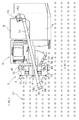
図1及び図2に示すように、右及び左のクローラ式の走行装置1で支持された機体の前部に刈取部2を備えて、機体の前部の右側部に運転部3、機体の後部の左側部に脱穀装置4、機体の後部の右側部にグレンタンク5を備えて、刈取収穫機の一例であるコンバインが構成されている。これにより、圃場の作物が刈取部2によって刈り取られ、刈り取られた作物が脱穀装置4に送られて脱穀処理され、脱穀処理されて単粒化した作物が収穫物としてグレンタンク5に貯留される。
As shown in FIG. 1 and FIG. 2, a
図1,2,3に示すように、機体に上下揺動自在に支持された主フレーム6に、刈取部2の全体が支持されており、主フレーム6を昇降駆動する昇降シリンダ7が備えられている。刈取部2は5個のデバイダ8,9,10,11、引き起し爪13aを多数備えた4組の引き起し装置13、バリカン型式の刈取装置14及び搬送装置15を備えて、4条刈り型式に構成されている。
As shown in FIGS. 1, 2, and 3, the
図1及び図2に示すように、内部にスクリュー(図示せず)を備えたアンローダ12がグレンタンク5の後部に備えられており、スクリューが回転駆動されることにより、グレンタンク5の収穫物が搬送され、アンローダ12の吐出口12aから排出される。アンローダ12は横軸芯P1周りに上下に昇降駆動自在に構成され、縦軸芯P2周りに旋回駆動自在に構成されている。図1及び図2に示す状態は、運転部3の後部に備えられた受け台17にアンローダ12を乗せた状態であり、アンローダ12を格納位置に配置した状態である。アンローダ12を格納位置から上昇駆動し、横外側に旋回駆動することにより、トラック(図示せず)の荷台にグレンタンク5の収穫物を排出する。
As shown in FIGS. 1 and 2, an
図1及び図3に示すように、刈取部2の右及び左側部の上部にカバー16が備えられており、右及び左のカバー16に右及び左のライト20が備えられている。右及び左のライト20は、上及び下のバルブ22,23、上及び下のバルブ22,23に対するリフレクタ(反射板)24,25、これらを覆う透明カバー21等を備えて構成されている。
As shown in FIGS. 1 and 3,
図1及び図3に示すように、右及び左のカバー16の前部16a及び横部16bに亘る角部に開口部が形成されて、右及び左のカバー16の開口部に右及び左のライト20が嵌め込まれるように固定されている。透明カバー21の前面が右及び左のカバー16の前部16a及び引き起し装置13の前面と略同一面(又は透明カバー21の前面が右及び左のカバー16の前部16a及び引き起し装置13の前面よりも少し後側)に位置するように構成されており、透明カバー21の横面が右及び左のカバー16の横部16bと略同一面に位置するように構成されている。
As shown in FIGS. 1 and 3, openings are formed at the corners across the
図3に示すように右のライト20において、上のバルブ22及びリフレクタ24が右のライト20の左右中央から右側(刈取部2の横外側)に位置し、下のバルブ23及びリフレクタ25が右のライト20の左右中央から左側(刈取部2の左右中央側)に位置している。リフレクタ24は上のバルブ22の光を前方に反射するように構成され、リフレクタ25は下のバルブ25の光を右斜め前方及び斜め下方に反射するように構成されている。これにより、刈取部2を地面に位置させている状態において、右のライト20の上のバルブ22の照射範囲RD1及び下のバルブ23の照射範囲RD2は、図5(a)及び図6に示すような状態となるのであり、右のライト20の下のバルブ23によりデバイダ8が照射されている。
As shown in FIG. 3, in the
図3に示すように左のライト20において、上のバルブ22及びリフレクタ24が左のライト20の左右中央から左側(刈取部2の横外側)に位置し、下のバルブ23及びリフレクタ25が左のライト20の左右中央から右側(刈取部2の左右中央側)に位置している。リフレクタ24は上のバルブ22の光を前方に反射するように構成され、リフレクタ25は下のバルブ25の光を左斜め前方及び斜め下方に反射するように構成されている。これにより、刈取部2を地面に位置させている状態において、左のライト20の上のバルブ22の照射範囲LD1及び下のバルブ23の照射範囲LD2は、図5(a)及び図6に示すような状態となるのであり、左のライト20の下のバルブ23によりデバイダ10が照射されている。
As shown in FIG. 3, in the
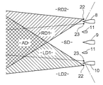
図6に示すように、刈取部2を地面に位置させている状態において、右のライト20の上のバルブ22の照射範囲RD1の左側部分と、左のライト20の上のバルブ22の照射範囲LD1の右側部分とが、刈取部2の前方で重なり合っている。この場合に、重なり合う部分ADが、刈取部2の中央の所定の近距離(例えば2メートル程度)から前方に位置する状態となる。図5(a)に示すように、刈取部2を地面に位置させている状態において、右及び左のライト20の上及び下のバルブ22,23の照射範囲RD1,RD2,LD1,LD2は斜め前方下方に向いている。
As shown in FIG. 6, in a state where the
図5(b)に示すように、刈取部2を上限位置まで上昇駆動すると、右及び左のライト20の上及び下のバルブ22,23の照射範囲RD1,RD2,LD1,LD2は、略前方を向く状態となる。この場合、前述の重なり合う部分AD(図6参照)が、刈取部2の中央の所定の遠距離(例えば8メートル程度)から前方に位置する状態となる。
As shown in FIG. 5B, when the
図1及び図2に示すように、アンローダ12の吐出口12aの前側部にライト18が下向きに取り付けられており、ライト18を上側から覆うカバー26が備えられている。受け台17にアンローダ12を乗せた状態(アンローダ12を格納位置に配置した状態)において、アンローダ12の吐出口12aがデバイダ9,11の前方上方の付近に位置している。これにより、刈取部2の中央直前の範囲SD(前述の重なり合う部分ADと刈取部2との間の付近)(図6参照)が、アンローダ12のライト18によって照射される。
As shown in FIGS. 1 and 2, a light 18 is attached downward to the front side of the
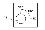
図4に示すように、運転部3にライトスイッチ19が備えられている。ライトスイッチ19をON2位置に操作すると、右及び左のライト20の上及び下のバルブ22,23が点灯し、アンローダ12のライト18が点灯する。ライトスイッチ19をON1位置に操作すると、右及び左のライト20の下のバルブ23が点灯して、右及び左のライト20の上のバルブ22が消灯し、アンローダ12のライト18が点灯する。ライトスイッチ19をOFF位置に操作すると、右及び左のライト20の上及び下のバルブ22,23が消灯し、アンローダ12のライト18が消灯する。
As shown in FIG. 4, the
コンバインでは例えば図2に示すように、刈取部2の運転部3とは反対側が未刈り側A1(作物がまだ刈り取られていない側)となり、刈取部2の運転部3側が既刈り側A2(作物が既に刈り取られた側)となる。この場合、デバイダ9,10,11は作物の株元付近に位置し作物よって隠れている状態で、運転部3からデバイダ9,10,11を目視できない状態である。これに対して、未刈り側A1の作物における既刈り側A2の端部の列B1の横外側にデバイダ8が位置しており、運転部3からデバイダ8を目視することができるのであり、未刈り側A1の作物における既刈り側A2の端部の列B1とデバイダ8との位置関係を目視しながら、運転部3の操縦者はコンバインの運転を行う。
この場合、右のライト20の上及び下のバルブ22,23により、未刈り側A1の作物における既刈り側A2の端部の列B1が照射されるようになるので、未刈り側A1の作物における既刈り側A2の端部の列B1を目視しながらの運転が行い易くなる。
In the combine, for example, as shown in FIG. 2, the side of the
In this case, the upper and
[発明の実施の第1別形態]
前述の[発明を実施するための最良の形態]に代えて、図7及び図8に示すように構成してもよい。
図7に示すように右のライト20において、上のバルブ22及びリフレクタ24が右のライト20の左右中央から左側(刈取部2の左右中央側)に位置し、下のバルブ23及びリフレクタ25が右のライト20の左右中央から右側(刈取部2の横外側)に位置している。リフレクタ24は上のバルブ22の光を前方に反射するように構成され、リフレクタ25は下のバルブ25の光を右斜め前方及び斜め下方に反射するように構成されている。これにより、刈取部2を地面に位置させている状態において、右のライト20の上のバルブ22の照射範囲RD1及び下のバルブ23の照射範囲RD2は、図5(a)及び図8に示すような状態となるのであり、右のライト20の下のバルブ23によりデバイダ8が照射されている。
[First Alternative Embodiment of the Invention]
Instead of the above-mentioned [Best Mode for Carrying Out the Invention], a configuration as shown in FIGS. 7 and 8 may be used.
As shown in FIG. 7, in the
図7に示すように左のライト20において、上のバルブ22及びリフレクタ24が左のライト20の左右中央から右側(刈取部2の左右中央側)に位置し、下のバルブ23及びリフレクタ25が左のライト20の左右中央から左側(刈取部2の横外側)に位置している。リフレクタ24は上のバルブ22の光を前方に反射するように構成され、リフレクタ25は下のバルブ25の光を左斜め前方及び斜め下方に反射するように構成されている。これにより、刈取部2を地面に位置させている状態において、左のライト20の上のバルブ22の照射範囲LD1及び下のバルブ23の照射範囲LD2は、図5(a)及び図8に示すような状態となるのであり、左のライト20の下のバルブ23によりデバイダ10が照射されている。
As shown in FIG. 7, in the
前述の[発明を実施するための最良の形態][発明の実施の第1別形態]において機体の前部の左側部に運転部3を備えるように構成してもよい。
It may be configured to include the best mode for carrying out the invention]
前述の[発明を実施するための最良の形態][発明の実施の第1別形態]において、ライト20に3個以上のバルブ22,23及びリフレクタ24,25を備えるように構成したり、ライト20に方向指示器(図示せず)や車幅灯(図示せず)を備えるように構成してもよい。ライト20の透明カバー21は無色透明のものばかりではなく、薄く着色(例えば薄い黄色)された半透明のものでもよい。
Oite to the aforementioned [BEST MODE FOR CARRYING OUT THE INVENTION] [First alternative embodiment of the invention, or configured to include three or
2 刈取部
13 引き起し装置
19 ライトスイッチ
20 ライト
21 透明カバー
22,23 バルブ
24,25 リフレクタ
2 Cutting part
13 Pulling device
19
Claims (6)
前記右のライトを、複数のバルブと、複数のバルブの各々に備えられた複数のリフレクタと、複数のバルブ及び複数のリフレクタを覆う縦長の透明カバーとを備えて構成すると共に、前記左のライトを、複数のバルブと、複数のバルブの各々に備えられた複数のリフレクタと、複数のバルブ及び複数のリフレクタを覆う縦長の透明カバーとを備えて構成し、
前記右のライトにおいて、複数のバルブのうちの一つのバルブと、複数のバルブのうちの別のバルブとを、透明カバーの内部に上下方向に位置ずれした状態で配備すると共に、前記左のライトにおいて、複数のバルブのうちの一つのバルブと、複数のバルブのうちの別のバルブとを、透明カバーの内部に上下方向に位置ずれした状態で配備し、
前記右のライトの透明カバーを、正面視で縦長のカバー前面と、側面視で縦長のカバー横面とで構成すると共に、前記左のライトの透明カバーを、正面視で縦長のカバー前面と、側面視で縦長のカバー横面とで構成し、
前記右のライトにおいて、複数のバルブのうちの一つのバルブの光の向きと、複数のバルブのうちの別のバルブの光の向きとが異なるものとなるように、一つのバルブの向き又は別のバルブの向き又はリフレクタの向きを設定すると共に、前記左のライトにおいて、複数のバルブのうちの一つのバルブの光の向きと、複数のバルブのうちの別のバルブの光の向きとが異なるものとなるように、一つのバルブの向き又は別のバルブの向き又はリフレクタの向きを設定している刈取収穫機。 A vertical right light with a cutting part at the front of the fuselage and on the lateral outer side of the upper part of the pulling device located on the rightmost side of the cutting part, overlapping with the upper part of the lifting device in side view. And a vertically long left light is provided on the lateral outer side of the upper part of the pulling device located on the leftmost side of the mowing part, in a state overlapping with the upper part of the pulling device in a side view,
The right light includes a plurality of bulbs, a plurality of reflectors provided in each of the plurality of bulbs, and a vertically long transparent cover that covers the plurality of bulbs and the plurality of reflectors, and the left light. Comprising a plurality of valves, a plurality of reflectors provided in each of the plurality of valves, and a vertically long transparent cover covering the plurality of valves and the plurality of reflectors,
In the right light, one valve of the plurality of valves and another valve of the plurality of valves are disposed in the transparent cover in a vertically displaced state, and the left light In the above, one valve of the plurality of valves and another valve of the plurality of valves are disposed in the transparent cover in a state of being vertically displaced,
The transparent cover of the right light is composed of a vertically long cover front in a front view and a vertically long cover horizontal in a side view, and the transparent cover of the left light is a vertically long cover front in a front view. It consists of a vertically long cover side view in side view,
In the right light, the light direction of one bulb of the plurality of bulbs and the light direction of another bulb of the plurality of bulbs are different from each other. In the left light, the light direction of one of the plurality of bulbs is different from the light direction of another of the plurality of bulbs. A harvesting and harvesting machine that sets the orientation of one valve, the orientation of another valve, or the orientation of a reflector so as to be.
Priority Applications (1)
| Application Number | Priority Date | Filing Date | Title |
|---|---|---|---|
| JP2010271417A JP5033233B2 (en) | 2010-12-06 | 2010-12-06 | Mowing harvester |
Applications Claiming Priority (1)
| Application Number | Priority Date | Filing Date | Title |
|---|---|---|---|
| JP2010271417A JP5033233B2 (en) | 2010-12-06 | 2010-12-06 | Mowing harvester |
Related Parent Applications (1)
| Application Number | Title | Priority Date | Filing Date |
|---|---|---|---|
| JP2007190020A Division JP4820339B2 (en) | 2007-07-20 | 2007-07-20 | Mowing harvester |
Publications (3)
| Publication Number | Publication Date |
|---|---|
| JP2011072313A JP2011072313A (en) | 2011-04-14 |
| JP2011072313A5 JP2011072313A5 (en) | 2011-05-26 |
| JP5033233B2 true JP5033233B2 (en) | 2012-09-26 |
Family
ID=44016995
Family Applications (1)
| Application Number | Title | Priority Date | Filing Date |
|---|---|---|---|
| JP2010271417A Active JP5033233B2 (en) | 2010-12-06 | 2010-12-06 | Mowing harvester |
Country Status (1)
| Country | Link |
|---|---|
| JP (1) | JP5033233B2 (en) |
Families Citing this family (2)
| Publication number | Priority date | Publication date | Assignee | Title |
|---|---|---|---|---|
| CN103875354B (en) * | 2012-12-19 | 2016-05-18 | 井关农机株式会社 | The reaping apparatus of united reaper |
| CN104838801B (en) * | 2015-02-02 | 2017-01-04 | 星光农机股份有限公司 | Cutter self stopping means under a kind of harvester |
Family Cites Families (3)
| Publication number | Priority date | Publication date | Assignee | Title |
|---|---|---|---|---|
| JPS55162525U (en) * | 1979-05-10 | 1980-11-21 | ||
| JPH058819Y2 (en) * | 1986-06-19 | 1993-03-04 | ||
| JP4185827B2 (en) * | 2002-09-24 | 2008-11-26 | ヤンマー農機株式会社 | Work vehicle lights |
-
2010
- 2010-12-06 JP JP2010271417A patent/JP5033233B2/en active Active
Also Published As
| Publication number | Publication date |
|---|---|
| JP2011072313A (en) | 2011-04-14 |
Similar Documents
| Publication | Publication Date | Title |
|---|---|---|
| JP4820339B2 (en) | Mowing harvester | |
| JP2007300938A5 (en) | ||
| JP5033233B2 (en) | Mowing harvester | |
| JP4043464B2 (en) | Mowing harvester | |
| JP4141425B2 (en) | Mowing harvester | |
| JP2011072313A5 (en) | ||
| JP5318500B2 (en) | Mowing harvester | |
| JP5717386B2 (en) | Combine | |
| JP4675423B2 (en) | Mowing harvester | |
| JP2011062120A (en) | Common combine harvester | |
| JP2014045694A (en) | Combine | |
| JP2009065989A (en) | Harvester | |
| JP7018761B2 (en) | combine | |
| JP4435229B2 (en) | Mowing harvester | |
| WO2012032795A1 (en) | Combine | |
| JP2006042755A (en) | Reaping harvester | |
| JP2006025666A (en) | Reaping harvester | |
| KR20240005623A (en) | Combine | |
| JP6991055B2 (en) | combine | |
| JP6887372B2 (en) | combine | |
| JP2016054674A (en) | Combine-harvester | |
| WO2022190832A1 (en) | Harvesting machine | |
| JP4107608B2 (en) | Harvester | |
| JP2006115799A (en) | Reaping harvester | |
| JP5033251B2 (en) | Harvesting machine |
Legal Events
| Date | Code | Title | Description |
|---|---|---|---|
| A521 | Written amendment |
Free format text: JAPANESE INTERMEDIATE CODE: A523 Effective date: 20110316 |
|
| TRDD | Decision of grant or rejection written | ||
| A01 | Written decision to grant a patent or to grant a registration (utility model) |
Free format text: JAPANESE INTERMEDIATE CODE: A01 Effective date: 20120531 |
|
| A01 | Written decision to grant a patent or to grant a registration (utility model) |
Free format text: JAPANESE INTERMEDIATE CODE: A01 |
|
| A61 | First payment of annual fees (during grant procedure) |
Free format text: JAPANESE INTERMEDIATE CODE: A61 Effective date: 20120629 |
|
| R150 | Certificate of patent or registration of utility model |
Ref document number: 5033233 Country of ref document: JP Free format text: JAPANESE INTERMEDIATE CODE: R150 Free format text: JAPANESE INTERMEDIATE CODE: R150 |
|
| FPAY | Renewal fee payment (event date is renewal date of database) |
Free format text: PAYMENT UNTIL: 20150706 Year of fee payment: 3 |