JP5031976B2 - Processing digital video data - Google Patents
Processing digital video data Download PDFInfo
- Publication number
- JP5031976B2 JP5031976B2 JP2003550513A JP2003550513A JP5031976B2 JP 5031976 B2 JP5031976 B2 JP 5031976B2 JP 2003550513 A JP2003550513 A JP 2003550513A JP 2003550513 A JP2003550513 A JP 2003550513A JP 5031976 B2 JP5031976 B2 JP 5031976B2
- Authority
- JP
- Japan
- Prior art keywords
- memory
- video data
- video
- block
- instruction
- Prior art date
- Legal status (The legal status is an assumption and is not a legal conclusion. Google has not performed a legal analysis and makes no representation as to the accuracy of the status listed.)
- Expired - Lifetime
Links
Images


Classifications
-
- H—ELECTRICITY
- H04—ELECTRIC COMMUNICATION TECHNIQUE
- H04N—PICTORIAL COMMUNICATION, e.g. TELEVISION
- H04N19/00—Methods or arrangements for coding, decoding, compressing or decompressing digital video signals
- H04N19/42—Methods or arrangements for coding, decoding, compressing or decompressing digital video signals characterised by implementation details or hardware specially adapted for video compression or decompression, e.g. dedicated software implementation
- H04N19/423—Methods or arrangements for coding, decoding, compressing or decompressing digital video signals characterised by implementation details or hardware specially adapted for video compression or decompression, e.g. dedicated software implementation characterised by memory arrangements
-
- H—ELECTRICITY
- H04—ELECTRIC COMMUNICATION TECHNIQUE
- H04N—PICTORIAL COMMUNICATION, e.g. TELEVISION
- H04N19/00—Methods or arrangements for coding, decoding, compressing or decompressing digital video signals
- H04N19/42—Methods or arrangements for coding, decoding, compressing or decompressing digital video signals characterised by implementation details or hardware specially adapted for video compression or decompression, e.g. dedicated software implementation
- H04N19/43—Hardware specially adapted for motion estimation or compensation
-
- H—ELECTRICITY
- H04—ELECTRIC COMMUNICATION TECHNIQUE
- H04N—PICTORIAL COMMUNICATION, e.g. TELEVISION
- H04N19/00—Methods or arrangements for coding, decoding, compressing or decompressing digital video signals
- H04N19/50—Methods or arrangements for coding, decoding, compressing or decompressing digital video signals using predictive coding
- H04N19/503—Methods or arrangements for coding, decoding, compressing or decompressing digital video signals using predictive coding involving temporal prediction
-
- H—ELECTRICITY
- H04—ELECTRIC COMMUNICATION TECHNIQUE
- H04N—PICTORIAL COMMUNICATION, e.g. TELEVISION
- H04N19/00—Methods or arrangements for coding, decoding, compressing or decompressing digital video signals
- H04N19/60—Methods or arrangements for coding, decoding, compressing or decompressing digital video signals using transform coding
- H04N19/61—Methods or arrangements for coding, decoding, compressing or decompressing digital video signals using transform coding in combination with predictive coding
Description
本発明は、ディジタルビデオデータの符号化または復号のような、ディジタルビデオデータの処理に関する。 The present invention relates to processing digital video data, such as encoding or decoding digital video data.
コンピュータ処理能力の最近の向上と、手頃な価格設定とのために、フルモーションディジタルビデオ受信機がより普及してきている。とくに、ディジタルビデオの能力は、ディジタルテレビジョン、ディジタル直接放送システム、無線通信装置、ポータブルディジタルアシスタント(portable digital assistant, PDA)、ラップトップコンピュータ、およびデスクトップコンピュータを含む幅広い範囲の装置に取入れられた。これらの装置は、フルモーションビデオ系列の生成、変更、伝送、記憶、および再生において従来のアナログビデオシステムよりも相当に向上している。 Full-motion digital video receivers have become more popular due to recent improvements in computer processing power and affordability. In particular, digital video capabilities have been incorporated into a wide range of devices including digital television, digital direct broadcast systems, wireless communication devices, portable digital assistants (PDAs), laptop computers, and desktop computers. These devices are a significant improvement over conventional analog video systems in the generation, modification, transmission, storage, and playback of full motion video sequences.
ディジタルビデオ系列と通信するための種々のビデオ圧縮の標準規格または処理が設定された。例えば、MPEG(Moving Picture Experts Group)(MPEG−1、MPEG−2、およびMPEG−4を含む)は、多数の標準規格を開発した。他の標準規格は、Apple Computer(Cupertino California)によって開発されたQuickTime(商標)技術、Microsoft Corporation(Redmond, Washington)によって開発されたVideo for Windows(商標)、Intel Corporationによって開発されたIndeo(商標)、RealNetworks, Inc(Seattle, Washington)からのRealVideo(商標)、およびSuperMac Inc.によって開発されたCinepak(商標)を含む。 Various video compression standards or processes have been established for communicating with digital video sequences. For example, the Moving Picture Experts Group (MPEG) (including MPEG-1, MPEG-2, and MPEG-4) has developed a number of standards. Other standards include QuickTime (TM) technology developed by Apple Computer (Cupertino California), Video for Windows (TM) developed by Microsoft Corporation (Redmond, Washington), Indeo (TM) developed by Intel Corporation RealVideos ™ from RealNetworks, Inc (Seattle, Washington), and Cinepak ™ developed by SuperMac Inc.
これらの標準規格の多くは、データ圧縮を用いることによって、より高い伝送レートを達成する。例えば、MPEGの標準規格は、ビデオおよび画像をより狭い帯域幅で伝送するように設計されたグラフィックおよびビデオ圧縮アルゴリズムを使用する。とくに、MPEGの標準規格は、連続する画像フレーム間の類似性(時間またはフレーム間相関と呼ばれる)を使用し、フレーム間圧縮を行なうビデオ圧縮技術を取入れている。フレーム間圧縮技術は、画像フレームの画素ベースの表現を、動き表現に変換することによって、フレーム全体におけるデータの冗長性を用いる。さらに加えて、ビデオ圧縮技術では、画像フレーム内の類似性(空間またはフレーム内相関と呼ばれる)を使用し、フレーム内圧縮をする。フレーム内圧縮では、画像フレーム内の動き表現を圧縮することができる。フレーム内圧縮は、一般に、離散コサイン変換(discrete cosine transform, DCT)符号化のような、静止画像を圧縮するための従来の処理に基づく。 Many of these standards achieve higher transmission rates by using data compression. For example, the MPEG standard uses graphics and video compression algorithms designed to transmit video and images with a narrower bandwidth. In particular, the MPEG standard incorporates video compression techniques that use inter-frame compression using the similarity between successive image frames (called temporal or inter-frame correlation). Interframe compression techniques use data redundancy in the entire frame by converting a pixel-based representation of an image frame into a motion representation. In addition, video compression techniques use similarity within image frames (called spatial or intraframe correlation) to perform intraframe compression. In-frame compression can compress motion representation within an image frame. Intraframe compression is generally based on conventional processing for compressing still images, such as discrete cosine transform (DCT) coding.
圧縮技術を支援するために、多くのディジタルビデオ装置は、ディジタルビデオ系列を圧縮および逆圧縮するための符号器/復号器(encoder/decoder, CODEC)を含む。CODECは、ビデオ画像系列内の画素ブロックを処理する。例えば、MPEGでは、CODECは、一般に、伝送されるビデオ画像フレームを、より小さい画像ブロックから成るマクロブロックへ分割する。画像フレーム内の各マクロブロックごとに、CODECは、直前のビデオフレームをサーチして、最も類似したマクロブロックを識別し、伝送するマクロブロック間の差を、符号化に使用された前のフレームからマクロブロックを示す動きベクトルと共に符号化する。復号器は、動きベクトルおよび符号化されたビデオデータを受信し、動き補償を行って、ビデオ系列を生成する。 In order to support compression techniques, many digital video devices include an encoder / decoder (CODEC) for compressing and decompressing digital video sequences. CODEC processes pixel blocks in a video image sequence. For example, in MPEG, CODEC typically divides a transmitted video image frame into macroblocks consisting of smaller image blocks. For each macroblock in the image frame, the CODEC searches the previous video frame to identify the most similar macroblock, and determines the difference between the transmitted macroblocks from the previous frame used for encoding. Coding with a motion vector indicating a macroblock. The decoder receives the motion vector and the encoded video data, performs motion compensation, and generates a video sequence.
概して、本発明は、ディジタルビデオデータの符号化または復号のような、ディジタルビデオデータの処理に関する。1つの実施形態では、本発明は、ビデオデータを記憶するための複数の線形アドレス指定可能な記憶装置をもつメモリと、ビデオデータの多次元ブロックを指定する命令に応答して、メモリの記憶装置にアクセスするためのプログラマブルビデオ直接メモリアクセス(video direct memory access, VDMA)制御装置とを含むシステムに関する。命令は、例えば、ビデオデータブロックの行番号および列番号と、ビデオブロックの各列間の記憶装置番号を示すジャンプパラメータとを指定する。このようにして、VDMA制御装置は、1つの直接メモリアクセス(direct memory access, DMA)命令に応答して、多数の不連続行をもつビデオデータのブロック全体をフェッチすることができる。したがって、マイクロプロセッサは、より少ないアドレス計算数で、ビデオデータのブロックにアクセスすることができる。 In general, the invention relates to processing digital video data, such as encoding or decoding digital video data. In one embodiment, the present invention provides a memory having a plurality of linear addressable storage devices for storing video data and a memory storage device in response to an instruction specifying a multidimensional block of video data. And a programmable video direct memory access (VDMA) controller for accessing the system. The instruction specifies, for example, a row number and a column number of the video data block, and a jump parameter indicating a storage device number between each column of the video block. In this way, the VDMA controller can fetch an entire block of video data having a number of discontinuous rows in response to a single direct memory access (DMA) instruction. Thus, the microprocessor can access a block of video data with a smaller number of address calculations.
別の実施形態において、本発明は、プロセッサから直接メモリアクセス(DMA)命令を受信して、ビデオデータの多次元ブロックを転送することと、命令に応答して、1組のソースアドレスおよび1組の宛先アドレスを生成することとを含む方法に関する。この方法は、ソースアドレスおよび宛先アドレスにしたがって、ソースメモリから宛先メモリへビデオデータをコピーすることも含む。 In another embodiment, the present invention receives a direct memory access (DMA) instruction from a processor to transfer a multidimensional block of video data and, in response to the instruction, a set of source addresses and a set. Generating a destination address of the device. The method also includes copying video data from the source memory to the destination memory according to the source address and the destination address.
別の実施形態において、本発明は、ディジタルビデオデータを処理するための装置に関する。装置は、符号化される候補のビデオブロックを記憶するための第1のメモリと、符号化される候補のビデオブロックを含むビデオデータブロックの組を記憶するための第2のメモリとを含む。装置は、候補のビデオブロックとビデオブロックの組との差分メトリックを計算するための差分計算器も含む。 In another embodiment, the present invention relates to an apparatus for processing digital video data. The apparatus includes a first memory for storing candidate video blocks to be encoded and a second memory for storing a set of video data blocks including candidate video blocks to be encoded. The apparatus also includes a difference calculator for calculating a difference metric between the candidate video block and the set of video blocks.
本発明の1つ以上の実施形態の詳細は、添付の図面および以下の説明において示される。本発明の他の特徴、目的、および長所は、説明および図面、並びに特許請求項から明らかになるであろう。 The details of one or more embodiments of the invention are set forth in the accompanying drawings and the description below. Other features, objects, and advantages of the invention will be apparent from the description and drawings, and from the claims.
本発明は、概して、ディジタルビデオデータの符号化または復号のような、ディジタルビデオデータの処理に関する。符号器、復号器、または符号器/復号器(CODEC)のような装置は、組込まれたプロセッサ、ディジタル信号プロセッサ、および専用のハードウエア間で機能を分割して、向上した性能を実現する革新的なアーキテクチャを含む。さらに加えて、装置のこれらの、および他の構成要素は、ビデオデータのブロックに直接にアクセスするための命令を支援する固有のメモリ構造を使用する。 The present invention relates generally to processing digital video data, such as encoding or decoding digital video data. Devices such as encoders, decoders, or encoder / decoders (CODECs) break down functionality between embedded processors, digital signal processors, and dedicated hardware to deliver improved performance Including typical architecture. In addition, these and other components of the device use a unique memory structure that supports instructions for directly accessing blocks of video data.
組込まれたプロセッサ、ディジタル信号プロセッサ、および専用ハードウエア間で符号化および復号機能を分割することによって、装置は、高速の符号化および復号を実現することができる。さらに加えて、組込まれたプロセッサおよびディジタル信号プロセッサ(digital signal processor, DSP)は、個々の圧縮標準規格に特定の全機能を実行し、一方で専用ハードウエアは、大抵の標準規格に共通する特定の計算を実行するように最適化される。このようにして、装置は高性能を実現するが、将来のビデオ圧縮の標準規格を支援するために、依然として、容易にアップグレードすることができる。 By splitting the encoding and decoding functions between the embedded processor, digital signal processor, and dedicated hardware, the device can achieve high speed encoding and decoding. In addition, embedded processors and digital signal processors (DSPs) perform all the functions specific to individual compression standards, while dedicated hardware is a specific common to most standards. Optimized to perform the calculation. In this way, the device achieves high performance, but can still be easily upgraded to support future video compression standards.
さらに加えて、ビデオデータのブロックに直接にアクセスするための命令を支援するプログラマブルビデオ直接メモリアクセス(video direct memory access, VDMA)制御装置を使用することによって、構成要素は、多数のアドレス計算を行う必要なく、ビデオデータのブロックにアクセスすることができる。言い換えると、構成要素は、従来の線形記憶アドレスの代わりに、ビデオデータのブロックを指定する命令を使用して、メモリ構造へデータを書込み、かつそこからデータを読み出すことができる。したがって、通常はビデオデータが順次に記憶されないために、ビデオデータにアクセスするのに通常必要とされる多数のアドレス計算を行う必要なく、構成要素は、ビデオデータのブロックにアクセスすることができる。 In addition, by using a programmable video direct memory access (VDMA) controller that supports instructions to directly access blocks of video data, the component performs a number of address calculations. A block of video data can be accessed without need. In other words, the component can write data to and read data from the memory structure using instructions that specify a block of video data instead of a conventional linear storage address. Thus, since video data is not typically stored sequentially, a component can access a block of video data without having to perform the numerous address calculations normally required to access the video data.
図1は、ソース装置4がビデオデータ6の符号化された系列を受信装置8へ送信する例示的なシステム2を示すブロック図である。とくに、ソース装置4は、種々のビデオ圧縮の標準規格の1つを使用して、ビデオデータ6を符号化して、送信する。このような標準規格の例は、Moving Picture Experts Groupによって開発されたMPEG、Apple Computer(Cupertino California)によって開発されたQuickTime(商標)、Microsoft Corporation(Redmond, Washington)によって開発されたVideo for Windows(商標)、Intel Corporationによって開発されたIndeo(商標)、およびSuperMac Inc.によって開発されたCinepak(商標)を含む。
FIG. 1 is a block diagram illustrating an exemplary system 2 in which a
ソース装置4は、ビデオデータ6を符号化して、送信することができる装置である。同様に、受信装置8は、ビデオデータ6を受信して、復号することができる装置である。ソース装置4および受信装置8の装置は、例えば、コンピュータネットワーク上に位置するサーバ、ワークステーションまたは他のデスクトップコンピュータ、およびラップトップコンピュータのようなモバイルコンピュータを含む。他の例は、ディジタルテレビジョン放送衛星および受信装置、例えば、ディジタルテレビジョン、ディジタルビデオカメラまたは他の記録装置、ディジタルビデオ電話装置、無線ビデオ装置、等を含む。
The
したがって、ソース装置4および受信装置8の各々は、一般に、ディジタルビデオデータ6を符号化および復号するための符号器/復号器(CODEC)(図示されていない)を含む。例えば、ソース装置4のCODECは、ビデオ画像系列内の画素ブロックを処理して、ビデオデータを符号化する。とくに、ソース装置4のCODECは、伝送されるビデオ画像フレームを、多数のより小さい画像ブロックから成るマクロブロックへ分割する。画像フレーム内の各マクロブロックごとに、ソース装置4のCODECは、既に伝送された前のビデオフレームをサーチして、最も類似したマクロブロックを識別し、マクロブロック間の差を、符号化に使用された前のフレームからマクロブロックを識別する動きベクトルと共に符号化する。受信装置8のCODECは、動きベクトルおよび符号化されたビデオデータを受信し、動き補償を行って、ユーザに表示するためのビデオ系列を生成する。ソース装置4および受信装置8の各々は、CODECを含む必要はない。例えば、ソース装置4が符号器を含み、受信装置8が復号器を含んでもよい。
Accordingly, each of the
ソース装置4のCODEC、受信装置8のCODEC、またはこの両者は、ビデオデータを符号化および復号するための革新的なアーキテクチャを含む。したがって、本発明は、符号化されたビデオデータを送信するための装置、または符号化されたビデオデータを受信するための装置に制限されない。符号化および復号の機能は、組込まれたプロセッサ、ディジタル信号プロセッサ、および専用ハードウエア間で分割される。さらに加えて、CODECのこれらの、および他の構成要素は、ビデオデータのブロックに直接にアクセスするための命令を支援する固有のメモリ構造を使用する。言い換えると、構成要素は、従来の線形記憶アドレスの代わりに、ビデオデータのブロックを指定する命令を使用して、メモリ構造へデータを書き込み、かつそこからデータを読み出すことができる。したがって、通常はビデオデータが順次に記憶されないために、ビデオデータにアクセスするのに通常必要とされる多数のアドレス計算を行う必要なく、構成要素は、ビデオデータのブロックにアクセスすることができる。
The
図2は、ソース装置4または受信装置6のような、例示的なディジタルビデオ装置10を示すブロック図であって、本発明の原理にしたがってディジタルビデオ系列を圧縮および逆圧縮するビデオ符号器/復号器(CODEC)20が組込まれている。例示的なディジタルビデオ装置10は、モバイルコンピュータ、パーソナルディジタルアシスタント(PDA)、無線通信装置、等のような無線装置として示される。しかしながら、本発明の原理は無線装置に制限されず、他のディジタルビデオ装置へ直ちに適用される。さらに加えて、本発明は、CODECに関連して示されているが、これに制限されず、符号器および復号器へ直ちに適用される。
FIG. 2 is a block diagram illustrating an exemplary
ディジタルビデオ装置10は、アンテナ12および送信機/受信機14を介して圧縮されたディジタルビデオ系列を受信する。CODEC20は、ビデオ系列を復号し、ビデオ系列をビデオメモリ15に記憶する。CODEC20は、復号されたビデオ系列をディスプレイ17上に表示する。ディスプレイ17は、液晶ディスプレイ(liquid crystal display, LCD)または他の出力装置を含む。さらに加えて、CODEC20は、画像センサー18によって取り込まれたディジタルビデオ系列を符号化する。CODEC20は、符号化されたディジタルビデオ系列を、送信機/受信機14およびアンテナ12を介して送信する前に、ビデオメモリ15内で緩衝する。メモリ16は、CODEC20が使用する指令およびデータを記憶する。メモリ15、16は、同期ダイナミックランダムアクセスメモリ(synchronous dynamic random access memory, SDRAM)、等を含む。
The
別途詳しく記載するように、CODEC20は、ビデオデータを符号化および復号するための革新的なアーキテクチャを含む。したがって、ディジタルビデオ装置10は、1.5メガビット/秒以上のような、ビデオデータの高速転送を実現する。
図3は、ディジタルビデオ装置10のCODEC20の例示的な実施形態をさらに詳しく示すブロック図である。概して、CODEC20は、組込まれたプロセッサ30、ディジタル信号プロセッサ(digital signal processor, DSP)28、および動き推定装置24間で、符号化および復号のタスクを分割する。多数の構成要素を含む1つの特定用途向け集積回路(application-specific integrated circuit, ASIC)として図示されているが、多数のディスクリートな構成要素を使用して、本明細書に記載されている原理を直ちに実行することができる。
As described in more detail below,
FIG. 3 is a block diagram illustrating in greater detail an exemplary embodiment of the
プロセッサ30は、CODEC20の全構成要素に対して主要な制御を与え、ディジタルビデオ装置10の他の構成要素との通信を調整する。プロセッサ30は、ディジタルビデオ系列を符号化および復号するのに必要な多数の計算を行う集中的なタスクを実行するように、DSP28へ命令する。また、幾つかのタスクにおいて、DSP28は動き推定装置24に関係する。動き推定装置24は、動き推定を行うための専用ハードウエアも含む。既に記載したように、メモリ16は、プロセッサ30によって使用するための指令およびデータを記憶し、一方で、ビデオメモリ15はビデオデータを記憶する。図示されているように、メモリ15、16は、CODEC20の外部にあり、プロセッサバス21を介してプロセッサ30に接続される。
The
プロセッサ30は、プロセッサバス21を介して、DSP28を構成し、制御する。DSP28は、指令およびデータを記憶するための専用メモリ41をもつが、DSPバス23を介してメモリ15、16へアクセスすることもできる。異なるDSPバス23を使用すると、DSP28およびプロセッサ30は、CODEC20の種々の構成要素に同時にアクセスすることができ、したがってディジタルビデオ装置10の全バンド幅が増す。例えば、DSP28がビデオメモリ15にアクセスし、一方で、プロセッサ30がメモリ16にアクセスすることができる。メモリ制御装置29は、プロセッサバス21、DSPバス23、および入力/出力(input/output, I/O)バス25間で、ビデオメモリ15へのアクセスを調停する。
The
I/Oバス25は、プロセッサ30およびDSP28を、ディスプレイ17および画像センサー18のような多数の異なる周辺装置へ接続する。プロセッサ30およびDSP28は、例えば、復号されたビデオデータをフレーム緩衝器38へ供給し、ディスプレイ制御装置37を介してディスプレイ17へ出力する。さらに加えて、プロセッサ30は、画像センサー18からビデオデータを取り込むようにように画像制御装置39に命令したり、ビデオメモリ15内にビデオデータを記憶したりする。
I /
プロセッサ30およびDSP28は、ビデオダイナミックメモリアクセス(VDMA)制御装置26を使用して、ビデオデータの効率的な符号化および復号を容易にする。とくに、プロセッサ30およびDSP28は、VDMA制御装置26に、ビデオデータの多次元ブロックを指定するアクセス命令を発行し、VDMA制御装置26は、それを一次元の記憶アドレスへ変換する。VDMA制御装置26は、プロセッサバス21およびDSPバス23の両者の上に位置し、外部メモリ16、ビデオメモリ15、DSPメモリ41、動き推定装置24内のメモリ(図示されていない)を含むCODEC20のメモリ間でデータを転送できるようにする。例えば、DSP28からの命令に応答して、VDMA制御装置26は、ビデオメモリ15から動き推定装置24へビデオデータの1つ以上のブロックをコピーする。
The
一度にメモリの一行を読み出す従来のDMA制御装置とは異なり、VDMA制御装置26は、行の間でプログラムし直す必要なく、フレームの多次元ビデオブロックをフェッチする。さらに加えて、VDMA制御装置26は、ビデオデータの非正方形のブロックをフェッチすることができる。このようにして、VDMAは、プロセッサ30、DSP28、およびCODEC20の他の構成要素が多数のアドレス計算をする必要を省いている。このような多数のアドレス計算は、通常はビデオデータが順次に記憶されないために、ビデオデータにアクセスするのに通常必要とされる。
Unlike conventional DMA controllers that read a row of memory at a time,
プロセッサ30およびDSP28は、転送するブロックを指定する1組のパラメータを含む命令を発行することによって、VDMA制御装置26をプログラムする。例えば、1つの命令は、次のパラメータを指定する。
ビデオブロック幅−バイトで表わされるデータブロックの幅(列数)。
ビデオブロック長−バイトで表わされるデータブロック長(行数)。
ソースメモリ開始アドレス−ソースメモリからデータを読み出すための開始アドレスであり、一般に、転送されるブロック内の左上の画素。
宛先メモリ開始アドレス−宛先メモリ内にデータを書込むための開始アドレス。
ジャンプ間隔−ある行の最後と次の行の最初との間のアドレスの個数をバイトで示すアドレスジャンプパラメータ。
ソースメモリワード幅−ソースメモリ内の1ワード当りのバイト数。
宛先メモリワード幅−宛先メモリ内の1ワード当りのバイト数。
ゼロパッドフラグ−データをゼロで埋めるかどうかを制御するブールフラグ。
Video block width- the width (number of columns) of the data block in bytes.
Video block length- data block length (number of rows) expressed in bytes.
Source memory start address— the start address for reading data from the source memory, generally the upper left pixel in the transferred block.
Destination memory start address— the start address for writing data into the destination memory.
Jump interval— an address jump parameter that indicates the number of addresses in bytes between the end of one line and the beginning of the next line.
Source memory word width— number of bytes per word in source memory.
Destination memory word width-the number of bytes per word in the destination memory.
Zero Pad Flag- A Boolean flag that controls whether data is filled with zeros.
上述のパラメータリストにおいて、ビデオブロック幅およびビデオブロック長は、バイトで表わされる希望の長方形のブロックの次元を定めるのに使用される。ソースメモリワード幅および宛先メモリワード幅により、VDMA制御装置26は、データを転送するときに、データパッキングが必要かどうかを判断することができる。例えば、ソースメモリが8ビット幅であり、宛先メモリが64ビット幅であるとき、VDMA制御装置26は、ソースメモリから8バイトを読み出し、それらを64ビットワードへパックし、宛先メモリへ書込む。
In the above parameter list, the video block width and video block length are used to define the dimensions of the desired rectangular block expressed in bytes. The source memory word width and the destination memory word width allow the
図4は、フレーム間で時間的な冗長を取り除くことによって、ビデオ系列を符号化する処理を示すフローチャートである。DSP28は、プロセッサ30の指示を受けて、ビデオメモリ15からビデオデータをフェッチして、動き推定装置24へ送るように、VDMA制御装置26をプログラムする(44)。とくに、DSP28は、ビデオメモリ15内のビデオデータの1つ以上のブロックを指定するビデオブロック移動命令を、VDMA制御装置26へ発行する。応答して、VDMA制御装置26は、不連続のビデオデータを、ビデオメモリ15から動き推定装置24の内部メモリへ転送するのに必要な全てのアドレス計算を行う。例えば、DSP28によって発行される命令に応答して、VDMA制御装置26は、伝送される現在のビデオブロックと、既に伝送されたビデオフレームとを、ビデオメモリ15から動き推定装置24へ転送する。
FIG. 4 is a flowchart showing a process for encoding a video sequence by removing temporal redundancy between frames. In response to an instruction from the
符号化処理は、DSP28と動き推定装置24との間で分割される。とくに、DSP28は、符号化アルゴリズムを実行するが、一般のデータ処理機能を実行するのには動き推定装置24を使用する。したがって、全サーチアルゴリズムが専用ハードウエア装置内で実行される従来のアプローチとは異なり、DSP28上で実行するソフトウエアは、動き推定装置24に変更を要求することなく、直ちに変更される。
The encoding process is divided between the
例えば、符号化処理中に、DSP28は、既に伝送されたビデオフレームをサーチして、符号化される現在のビデオブロックに最も類似したビデオブロックを識別する命令を、動き推定装置24へ発行する(46)。この命令は、現在のブロックを選択し、かつ前のビデオフレームのブロックと比較するのに必要な全情報を指定する。さらに加えて、命令は、一般のフォーマットにしたがっており、従来のサーチングアルゴリズムで直ちに使用される。例えば、命令は、サーチ空間の左上角部の(X,Y)座標、サーチ空間の右左下角部の(X,Y)座標、およびある行の最後と次の行の最初との距離をバイトで示すジャンプ値を指定する。
For example, during the encoding process, the
命令に応答して、動き推定装置24は、符号化される現在のビデオブロックと、前のフレームのブロックとを比較して、ブロックの歪みメトリックの組と、各動きベクトルとを出力する(48)。歪みメトリックは、伝送されるブロックと、前のフレームの種々のブロックとの差を相対的に示す。動き推定装置24は、並行して計算を行い、サーチ空間内の各ブロック歪みメトリックを生成する。
In response to the command,
歪みメトリックを計算するために、動き推定装置24は、既に伝送されたビデオフレームと、符号化される現在のブロックとを使用して、多数のアルゴリズムの1つを実行する。動き推定装置24は、符号化されるブロックと、前のビデオフレーム内のブロックとにおいて、例えば、絶対差の和(Sum of Absolute the Difference, SAD)または平方差の和(Sum of the Squared Difference, SSD)を計算する。その代りに、動き推定装置24は、ビデオデータ間の平均平方誤差(Mean Square Error, MSE)を計算するか、または正規化相互相関関数(Normalized Cross Correlation Function, NCCF)を実行してもよい。
To calculate the distortion metric,
DSP28は、歪みメトリックに基づいて、サーチ空間内の1つまたは複数の最整合ブロックを識別する(50)。DSP28は、例えば、MPEGの符号化されたビデオデータにおいて、最も近いマクロブロックを示す1つの動きベクトルか、または4つのブロックを示す4つの動きベクトルを選択する。DSP28は、最整合ブロックを判断すると、データを符号化するための多数の画像処理機能を実行する(52)。例えば、DSP28は、転送されるブロックから、選択されたブロックを減算することによって動き補償を行う。さらに加えて、DSP28は、離散コサイン変換(DCT)を実行して、信号エネルギーを係数および量子化へパックし、符号化するビット数を低減する。プロセッサ30は、伝送のために二次元の係数データを一次元へ変換するための走査と、ヘッダおよび圧縮パラメータを追加するためのビットストリームの符号化とを行なう。最後に、プロセッサ30は、送信機/受信機14と対話して、DSP28によって生成された符号化されたデータを伝送する(54)。
The
このようにして、CODEC20は、プロセッサ30、DSP28、および動き推定装置24の間で、動き推定およびビデオ圧縮タスクを分割する。とくに、プロセッサ30は、高レベルの監視役で働き、DSP28は、非常に多くの計算を行なう符号化アルゴリズムを処理し、動き推定装置24は、専用ハードウエアを使用して、高速のサーチを行なう。CODEC20は、この分割により高い性能を実現できるが、将来のビデオ圧縮の標準規格を支援するために、依然として容易にアップグレード可能である。さらに加えて、組込まれたプロセッサがサーチング技術を全体的に実行する従来のアプローチよりも、プロセッサ30の計算の負荷およびCODEC20の電力消費量を相当に低減することができる。
In this way, the
図5は、動き推定装置24の例示的な実施形態をさらに詳しく示すブロック図である。動き推定装置24は、符号化される現在のブロックをキャッシュするための2つの内部高速メモリ60、62と、現在のブロックを差別的に符号化するのに使用するためのビデオデータとを含む。とくに、動き推定装置24は、符号化される現在のブロックを記憶するためのブロックメモリ60を含む。さらに加えて、動き推定装置24は、既に伝送された最も近いビデオブロックを識別するデータを含む全データを記憶するためのサーチ空間メモリ62を含む。例えば、MPEGを支援する実施形態において、ブロックメモリ60は、伝送されるマクロブロックを記憶し、一方でサーチ空間メモリ62は、既に伝送されたビデオフレームのような、複数の既に伝送されたマクロブロックを記憶する。この構成では、通常のブロックは8×8バイトから成り、マクロブロックは16×16バイトから成り、サーチ空間は48×48バイトから成る。
FIG. 5 is a block diagram illustrating an exemplary embodiment of the
差分計算器64は、メモリ60、62からビデオデータを検索するためのアドレス生成論理を含む。符号化処理中に、VDMA制御装置26は、ビデオメモリ15から現在のブロックをフェッチし、現在のブロックをメモリ60内に記憶する。さらに加えて、VDMA制御装置26は、前のビデオフレーム内のサーチ空間をフェッチし、サーチ空間メモリ62内にビデオデータを記憶する。したがって、DSP28は、指定されたビデオデータを、動き推定装置24の各内部メモリ60、62へ転送するように、VDMA制御装置26をプログラムする。とくに、DSP28は、ビデオブロック移動命令をビデオVDMA制御装置26へ発行し、ビデオメモリ15内の不連続のビデオデータブロックと、メモリ15、60、62のワード幅のような他の必要なパラメータとを指定し、VDMA制御装置26がメモリ15、60、62間で不連続のビデオデータを正しく転送できるようにする。
The
差分計算器64は、DSP28からサーチ命令72を受信すると、メモリ60、62内に記憶されているビデオデータを検索し、ビデオデータ間で画素に関する比較を行って、1つ以上の差分メトリックを計算する。各サーチ命令72は、差分メトリックを生成するのに使用するための、メモリ62内のビデオデータの多次元領域を指定する。例として、各サーチ命令72は、メモリ62内の領域の左上角部と右下角部とを指定する。
When the
したがって、DSP28は、動き推定アルゴリズムの実行中に、メモリ60、62によって記憶されたビデオデータを何度も使用するように、差分計算器64に命令する。符号化される現在のブロックおよび全サーチ空間をメモリ60、62内にそれぞれ内部キャッシュすることによって、動き推定装置24は、サーチ間に、ビデオメモリ15にアクセスする必要がなくなる。したがって、CODEC20は、従来のアーキテクチャに関係する符号化速度を増すことができる。
Accordingly, the
差分メトリックを計算するために、差分計算器64は、多数のアルゴリズムの1つを実行し、メモリ60内に記憶されている現在のブロックと、サーチ空間メモリ62内の種々のブロックとの差を示す出力を生成する。既に記載したように、差分計算器64は、符号化されるブロックと前のビデオフレーム内のブロックとの絶対差の和(SAD)または平方差の和(SSD)を実行する。その代りに、差分計算器64は、平均平方誤差(MSE)または正規化相互相関関数(NCCF)を実行してもよい。
In order to calculate the difference metric,
差分測定値および動きベクトルを計算するとき、差分計算器64は、中断(interrupt, INT)66をアサートし、保留中の結果についてDSP28に知らせる。中断数を低減するために、動き推定装置24は、命令(command, CMD)緩衝器70を含み、DSP28から受信したサーチ命令72を記憶する。CMD緩衝器70は、例えば、受信した命令を緩衝するための先入れ先出し(first-in first-out, FIFO)待ち行列を含む。したがって、DSP28は、結果を報告する前に、動き推定装置24によって実行される複数のサーチを指定することができる。
When calculating difference measurements and motion vectors,
図6は、メモリ60内に記憶される例示的なマクロブロック80を示す。既に記載したように、この実行は、MPEG、およびマクロブロックを使用する他のビデオ圧縮方式において有益である。とくに、マクロブロック80は、ビデオデータの4つのブロック82Aないし82Dを含む。この実施形態では、差分計算器64のアドレス生成論理は、4つのブロック82の何れかにアクセスするように構成されている。各ブロック82が8バイト(M/2)の幅と8バイト(N/2)の長さとをもち、マクロブロック60が8バイトのワード幅をもつ例示的な構成について検討する。この構成では、メモリ60内において、ブロック82Aおよび82Bの行は交互になり、ブロック82Cおよび82Dの交互の行が続く。したがって、各ブロック82の差分メトリックを計算するために、差分計算器64のアドレス生成論理は、直列または並列に、個々のブロック82をフェッチするアドレスを生成する。
FIG. 6 shows an
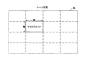
図7は、MPEGおよび他のビデオ圧縮方式で使用するのに有益なサーチ空間メモリ62内に記憶される例示的なサーチ空間84を示す。とくに、サーチ空間84は、ビデオデータを記憶し、その一部は差の計算に使用される。
1つの構成において、差分計算器64のアドレス生成論理は、サーチ空間メモリ62からM×4の連続するバイトをフェッチするためのアドレスを生成する。したがって、多数の候補のブロックの差分メトリックを並列に計算することができる。
FIG. 7 illustrates an
In one configuration, the address generation logic of the
図8は、図7に示されているようなM×N次元のマクロブロックを含むサーチ空間を記憶するためのサーチ空間メモリ62の例示的な構成を示す。とくに、サーチ空間メモリ62は、Mバイト幅のメモリ90を含む。1サイクルにおいて、レジスタ92はメモリ90からMバイトを受信し、バイトを連結してから、検索されたデータを差分計算器64へ送る。したがって、差分計算器64は、1クロックサイクルにおいて、マクロブロック内のブロックの1つからビデオデータの行全体をフェッチすることができる。ブロックの連続する行は、メモリ90内で隣り合っていないので、差分計算器64のアドレス生成論理は、ブロック全体をフェッチするために、アクセスのたびにアドレスをジャンプする。
FIG. 8 shows an exemplary configuration of a
図9は、本発明の原理にしたがって、ビデオ系列を復号する処理を示すフローチャートである。プロセッサ30またはCODEC20は、送信機/受信機14およびアンテナ12を介して、符号化されたビデオ系列を受信する(100)。その後で、プロセッサ30は、受信ビットストリームをアンパックして、逆量子化および逆離散コサイン変換(inverse discrete cosine transformation, IDCT)を行うことによって、ビデオデータを前処理する(102)。
FIG. 9 is a flowchart illustrating a process for decoding a video sequence in accordance with the principles of the present invention.
次に、プロセッサ30は、受信した動きベクトルが、もしあれば、それを、既に受信したビデオデータへ適用することによって動き補償を行う(104)。この処理中に、プロセッサ30は、VDMA制御装置26を使用して、ブロック命令を用いて、既に伝送されたデータをビデオメモリ15から検索する。同様に、プロセッサ30は、生成されたビデオデータをビデオメモリ15へ転送するように、VDMA制御装置26に命令する。
Next, the
次に、プロセッサ30は、圧縮アルゴリズムによって取入れられるブロッキング効果を取除き、かつ必要な色変換を行う後処理をビデオデータに行うように、DSP28に命令する(106)。DSP28は、VDMAを使用して、ビデオメモリ15からビデオデータを検索し、後処理されたビデオデータをビデオメモリ15へ記憶する。
Next, the
最後に、プロセッサ30は、ユーザが見るために、復号されたビデオデータをディスプレイ17に表示するように、ディスプレイ制御装置37に命令する。とくに、プロセッサ30は、VDMA制御装置26を呼出して、復号されたビデオデータをビデオメモリ15からフレーム緩衝器38へ転送する。
Finally, the
本発明の種々の実施形態を記載した。これらの、および他の実施形態は、特許請求項の技術的範囲内である。 Various embodiments of the invention have been described. These and other embodiments are within the scope of the claims.
2・・・システム、6・・・ビデオデータ、21・・・プロセッサバス、23・・・DSPバス、25・・・入力/出力(I/O)バス。 2 ... System, 6 ... Video data, 21 ... Processor bus, 23 ... DSP bus, 25 ... Input / output (I / O) bus.
Claims (31)
ビデオデータの多次元ブロックを指定する命令に応答して、メモリの記憶装置にアクセスし、命令に応答して、メモリの多数の非連続行からビデオデータの多次元ブロックをフェッチするためのプログラマブルビデオ直接メモリアクセス(video direct memory access, VDMA)制御装置とを含み、命令はビデオデータのブロックの各行間の記憶装置の個数を示すジャンプパラメータを指定する、システム。A memory having a linear addressable storage for storing video data;
Programmable video for accessing a memory storage device in response to an instruction specifying a multidimensional block of video data and fetching the multidimensional block of video data from a number of non-contiguous rows of memory in response to the instruction A system that includes a video direct memory access (VDMA) controller, wherein the instructions specify jump parameters indicating the number of storage devices between each row of blocks of video data.
第2のバスを介してVDMA制御装置へ命令を発行するためのディジタル信号プロセッサとをさらに含む請求項1記載のシステム。A processor for issuing instructions to the VDMA controller via the first bus;
The system of claim 1, further comprising a digital signal processor for issuing instructions to the VDMA controller over the second bus.
命令に応答して、ビデオデータの多次元ブロックのためのソースアドレスの組と宛先アドレスの組とを生成し、ソースアドレスの組が、ソースメモリの多数の非連続行に対応することと、
命令に応答して、ソースアドレスおよび宛先アドレスにしたがって、ソースメモリから宛先メモリへビデオデータをコピーすることとを含む方法。Receiving a direct memory access (DMA) instruction from the processor and transferring a multidimensional block of video data, the instruction specifying a jump parameter indicating the number of storage devices between each row of the block of video data When,
In response to the instructions, generating a set of source addresses and a set of destination addresses for a multidimensional block of video data, the set of source addresses corresponding to a number of non-contiguous rows of source memory;
Responsive to the instruction, copying video data from the source memory to the destination memory according to the source address and the destination address.
符号化される候補のビデオブロックを含むビデオデータブロックの組を記憶するための第2のメモリと、
候補のビデオブロックとビデオブロックの組との差分メトリックを計算するための差分計算器と、
候補のビデオブロックとビデオブロックの組とをビデオメモリから第1のメモリおよび第2のメモリにそれぞれコピーするためのプログラマブルビデオ直接メモリアクセス(VDMA)制御装置であって、ビデオメモリ内に多数の非連続行で記憶されているビデオデータの多次元サーチ空間を特定する1つの直接メモリアクセス(DMA)命令に応答して、ブロックの組を第2のメモリにコピーするVDMA制御装置とを含み、命令はビデオデータのブロックの各行間の記憶装置の個数を示すジャンプパラメータを指定する、装置。A first memory for storing candidate video blocks to be encoded;
A second memory for storing a set of video data blocks including candidate video blocks to be encoded;
A difference calculator for calculating a difference metric between the candidate video block and the set of video blocks;
A programmable video direct memory access (VDMA) controller for copying a candidate video block and a set of video blocks from a video memory to a first memory and a second memory, respectively, wherein a plurality of non- A VDMA controller for copying a set of blocks to a second memory in response to one direct memory access (DMA) instruction specifying a multidimensional search space of video data stored in consecutive rows, the instruction Specifies a jump parameter indicating the number of storage devices between each row of a block of video data.
第2のバスを介してVDMA制御装置へ命令を発行するためのディジタル信号プロセッサ(DSP)とをさらに含む請求項15記載の装置。A processor for issuing instructions to the VDMA controller via the first bus;
16. The apparatus of claim 15, further comprising a digital signal processor (DSP) for issuing instructions to the VDMA controller over the second bus.
命令に応答して、ビデオデータの多次元ブロックのソースアドレスの組と宛先アドレスの組とを生成するための手段であって、ソースアドレスの組がソースメモリの多数の非連続行に対応する手段と、
ソースアドレスおよび宛先アドレスにしたがって、ソースメモリから宛先メモリへビデオデータをコピーするための手段とを含む装置。A means for receiving a direct memory access (DMA) instruction from a processor and transferring a multidimensional block of video data, the instruction specifying a jump parameter indicating the number of storage devices between each row of the block of video data Means,
Means for generating a source address set and a destination address set for a multidimensional block of video data in response to an instruction, the source address set corresponding to a number of non-contiguous rows of source memory When,
Means for copying video data from a source memory to a destination memory according to a source address and a destination address.
Applications Claiming Priority (3)
| Application Number | Priority Date | Filing Date | Title |
|---|---|---|---|
| US10/006,044 | 2001-12-04 | ||
| US10/006,044 US7236177B2 (en) | 2001-12-04 | 2001-12-04 | Processing digital video data |
| PCT/US2002/038666 WO2003049454A2 (en) | 2001-12-04 | 2002-12-03 | Processing digital video data |
Related Child Applications (1)
| Application Number | Title | Priority Date | Filing Date |
|---|---|---|---|
| JP2010248701A Division JP5490661B2 (en) | 2001-12-04 | 2010-11-05 | Processing digital video data |
Publications (3)
| Publication Number | Publication Date |
|---|---|
| JP2006501697A JP2006501697A (en) | 2006-01-12 |
| JP2006501697A5 JP2006501697A5 (en) | 2006-02-23 |
| JP5031976B2 true JP5031976B2 (en) | 2012-09-26 |
Family
ID=21719010
Family Applications (3)
| Application Number | Title | Priority Date | Filing Date |
|---|---|---|---|
| JP2003550513A Expired - Lifetime JP5031976B2 (en) | 2001-12-04 | 2002-12-03 | Processing digital video data |
| JP2010248701A Expired - Lifetime JP5490661B2 (en) | 2001-12-04 | 2010-11-05 | Processing digital video data |
| JP2013222795A Pending JP2014060746A (en) | 2001-12-04 | 2013-10-25 | Processing digital video data |
Family Applications After (2)
| Application Number | Title | Priority Date | Filing Date |
|---|---|---|---|
| JP2010248701A Expired - Lifetime JP5490661B2 (en) | 2001-12-04 | 2010-11-05 | Processing digital video data |
| JP2013222795A Pending JP2014060746A (en) | 2001-12-04 | 2013-10-25 | Processing digital video data |
Country Status (6)
| Country | Link |
|---|---|
| US (1) | US7236177B2 (en) |
| EP (1) | EP1454494B1 (en) |
| JP (3) | JP5031976B2 (en) |
| KR (1) | KR100952861B1 (en) |
| AU (1) | AU2002346638A1 (en) |
| WO (1) | WO2003049454A2 (en) |
Families Citing this family (32)
| Publication number | Priority date | Publication date | Assignee | Title |
|---|---|---|---|---|
| US7523482B2 (en) * | 2002-08-13 | 2009-04-21 | Microsoft Corporation | Seamless digital channel changing |
| US8397269B2 (en) | 2002-08-13 | 2013-03-12 | Microsoft Corporation | Fast digital channel changing |
| US7266151B2 (en) * | 2002-09-04 | 2007-09-04 | Intel Corporation | Method and system for performing motion estimation using logarithmic search |
| US20040042551A1 (en) * | 2002-09-04 | 2004-03-04 | Tinku Acharya | Motion estimation |
| US20040057626A1 (en) * | 2002-09-23 | 2004-03-25 | Tinku Acharya | Motion estimation using a context adaptive search |
| US7603689B2 (en) * | 2003-06-13 | 2009-10-13 | Microsoft Corporation | Fast start-up for digital video streams |
| US7562375B2 (en) | 2003-10-10 | 2009-07-14 | Microsoft Corporation | Fast channel change |
| US7444419B2 (en) * | 2003-10-10 | 2008-10-28 | Microsoft Corporation | Media stream scheduling for hiccup-free fast-channel-change in the presence of network chokepoints |
| US7430222B2 (en) * | 2004-02-27 | 2008-09-30 | Microsoft Corporation | Media stream splicer |
| US20070246539A1 (en) * | 2004-06-30 | 2007-10-25 | Anoto Ab | Data Processing in an Electric Pen |
| SE0401687D0 (en) * | 2004-06-30 | 2004-06-30 | Anoto Ab | Information management |
| US20080296074A1 (en) * | 2004-06-30 | 2008-12-04 | Anoto Ab | Data Management in an Electric Pen |
| US7640352B2 (en) * | 2004-09-24 | 2009-12-29 | Microsoft Corporation | Methods and systems for presentation of media obtained from a media stream |
| EP1815314B1 (en) * | 2004-11-05 | 2014-09-03 | Anoto AB | Method and device for data management in an electronic pen |
| US7715645B2 (en) * | 2004-11-17 | 2010-05-11 | Samsung Electronics Co., Ltd. | Methods to estimate noise variance from a video sequence |
| US7477653B2 (en) * | 2004-12-10 | 2009-01-13 | Microsoft Corporation | Accelerated channel change in rate-limited environments |
| US20060168629A1 (en) * | 2005-01-27 | 2006-07-27 | Inventec Multimedia & Telecom Corporation | Digitized wireless remote control apparatus and method for personal video recorder |
| US7570819B2 (en) * | 2005-01-28 | 2009-08-04 | Chih-Ta Star Sung | Method and apparatus for displaying images with compression mechanism |
| US7714939B2 (en) * | 2005-04-05 | 2010-05-11 | Samsung Electronics Co., Ltd. | Reliability estimation of temporal noise estimation |
| KR100686393B1 (en) | 2005-04-07 | 2007-03-02 | 주식회사 텔레칩스 | Motion estimation device and method suitable hardware implementation |
| US7512752B2 (en) * | 2005-05-31 | 2009-03-31 | Broadcom Corporation | Systems, methods, and apparatus for pixel fetch request interface |
| US7859574B1 (en) * | 2005-07-19 | 2010-12-28 | Maxim Integrated Products, Inc. | Integrated camera image signal processor and video encoder |
| US20070110503A1 (en) * | 2005-10-31 | 2007-05-17 | Glover J S | Dispensing brush with replaceable cartridge/handle part |
| US8135040B2 (en) * | 2005-11-30 | 2012-03-13 | Microsoft Corporation | Accelerated channel change |
| US9131240B2 (en) * | 2007-08-23 | 2015-09-08 | Samsung Electronics Co., Ltd. | Video decoding method and apparatus which uses double buffering |
| US8264529B2 (en) * | 2009-02-25 | 2012-09-11 | T-Mobile Usa, Inc. | Camera pod that captures images or video when triggered by a mobile device |
| US9148699B2 (en) * | 2012-06-01 | 2015-09-29 | Texas Instruments Incorporated | Optimized algorithm for construction of composite video from a set of discrete video sources |
| US9930353B2 (en) * | 2013-03-29 | 2018-03-27 | Sony Corporation | Image decoding device and method |
| US9800886B2 (en) | 2014-03-07 | 2017-10-24 | Lattice Semiconductor Corporation | Compressed blanking period transfer over a multimedia link |
| US20150271512A1 (en) * | 2014-03-18 | 2015-09-24 | Texas Instruments Incorporated | Dynamic frame padding in a video hardware engine |
| KR20180086792A (en) * | 2017-01-23 | 2018-08-01 | 삼성전자주식회사 | Method for processing data among a plurality of processors and electronic device thereof |
| US10652456B2 (en) * | 2017-05-31 | 2020-05-12 | Intel IP Corporation | Image sensor operation |
Family Cites Families (10)
| Publication number | Priority date | Publication date | Assignee | Title |
|---|---|---|---|---|
| KR0129557B1 (en) * | 1992-10-07 | 1998-04-10 | 배순훈 | Memory apparatus in a motion picture data processor using a motion compensation |
| US6301299B1 (en) * | 1994-10-28 | 2001-10-09 | Matsushita Electric Industrial Co., Ltd. | Memory controller for an ATSC video decoder |
| US5596376A (en) * | 1995-02-16 | 1997-01-21 | C-Cube Microsystems, Inc. | Structure and method for a multistandard video encoder including an addressing scheme supporting two banks of memory |
| US6335950B1 (en) * | 1997-10-14 | 2002-01-01 | Lsi Logic Corporation | Motion estimation engine |
| US6104416A (en) * | 1997-11-18 | 2000-08-15 | Stmicroelectronics, Inc. | Tiling in picture memory mapping to minimize memory bandwidth in compression and decompression of data sequences |
| US6028612A (en) * | 1997-11-18 | 2000-02-22 | Stmicroelectronics, Inc. | Picture memory mapping to minimize memory bandwidth in compression and decompression of data sequences |
| US6313766B1 (en) * | 1998-07-01 | 2001-11-06 | Intel Corporation | Method and apparatus for accelerating software decode of variable length encoded information |
| JP2000175199A (en) * | 1998-12-04 | 2000-06-23 | Sony Corp | Image processor, image processing method and providing medium |
| JP3626687B2 (en) * | 1998-12-15 | 2005-03-09 | 松下電器産業株式会社 | Image processing device |
| KR100677082B1 (en) * | 2000-01-27 | 2007-02-01 | 삼성전자주식회사 | Motion estimator |
-
2001
- 2001-12-04 US US10/006,044 patent/US7236177B2/en not_active Expired - Lifetime
-
2002
- 2002-12-03 WO PCT/US2002/038666 patent/WO2003049454A2/en active Application Filing
- 2002-12-03 EP EP02784710.2A patent/EP1454494B1/en not_active Expired - Lifetime
- 2002-12-03 AU AU2002346638A patent/AU2002346638A1/en not_active Abandoned
- 2002-12-03 KR KR1020047008688A patent/KR100952861B1/en active IP Right Grant
- 2002-12-03 JP JP2003550513A patent/JP5031976B2/en not_active Expired - Lifetime
-
2010
- 2010-11-05 JP JP2010248701A patent/JP5490661B2/en not_active Expired - Lifetime
-
2013
- 2013-10-25 JP JP2013222795A patent/JP2014060746A/en active Pending
Also Published As
| Publication number | Publication date |
|---|---|
| AU2002346638A1 (en) | 2003-06-17 |
| KR100952861B1 (en) | 2010-04-13 |
| EP1454494A2 (en) | 2004-09-08 |
| JP2014060746A (en) | 2014-04-03 |
| JP5490661B2 (en) | 2014-05-14 |
| JP2006501697A (en) | 2006-01-12 |
| EP1454494B1 (en) | 2018-09-26 |
| WO2003049454A2 (en) | 2003-06-12 |
| US20030106053A1 (en) | 2003-06-05 |
| WO2003049454A3 (en) | 2003-09-04 |
| KR20050058276A (en) | 2005-06-16 |
| US7236177B2 (en) | 2007-06-26 |
| JP2011083000A (en) | 2011-04-21 |
Similar Documents
| Publication | Publication Date | Title |
|---|---|---|
| JP5490661B2 (en) | Processing digital video data | |
| US5912676A (en) | MPEG decoder frame memory interface which is reconfigurable for different frame store architectures | |
| US6067322A (en) | Half pixel motion estimation in motion video signal encoding | |
| EP0849953B1 (en) | System and method for performing motion compensation using a skewed tile storage format for improved efficiency | |
| JP3142772B2 (en) | Processor and transfer method | |
| TWI364714B (en) | Caching method and apparatus for video motion compensation | |
| US20050190976A1 (en) | Moving image encoding apparatus and moving image processing apparatus | |
| KR100772379B1 (en) | External memory device, method for storing image date thereof, apparatus for processing image using the same | |
| US7885336B2 (en) | Programmable shader-based motion compensation apparatus and method | |
| US20060133512A1 (en) | Video decoder and associated methods of operation | |
| JP4346573B2 (en) | Encoding apparatus and method | |
| Ramkishor et al. | Real time implementation of MPEG-4 video decoder on ARM7TDMI | |
| US6720893B2 (en) | Programmable output control of compressed data from encoder | |
| EP0660608B1 (en) | Image processor | |
| WO2007055013A1 (en) | Image decoding apparatus and method, and image encoding apparatus | |
| US6097843A (en) | Compression encoding apparatus, encoding method, decoding apparatus, and decoding method | |
| JP2000175201A (en) | Image processing unit, its method and providing medium | |
| US6873735B1 (en) | System for improved efficiency in motion compensated video processing and method thereof | |
| KR100636911B1 (en) | Method and apparatus of video decoding based on interleaved chroma frame buffer | |
| US20090201989A1 (en) | Systems and Methods to Optimize Entropy Decoding | |
| Purcell et al. | C-Cube MPEG video processor | |
| JP2001045493A (en) | Moving image encoding device, moving image output device and storage medium | |
| Onoye et al. | Single chip implementation of MPEG2 decoder for HDTV level pictures | |
| KR20040073095A (en) | A Device for Both Encoding and Decoding MPEG or JPEG Data | |
| CN116723323A (en) | Video encoding method, video encoding device, electronic equipment and readable storage medium |
Legal Events
| Date | Code | Title | Description |
|---|---|---|---|
| A521 | Request for written amendment filed |
Free format text: JAPANESE INTERMEDIATE CODE: A523 Effective date: 20051201 |
|
| A621 | Written request for application examination |
Free format text: JAPANESE INTERMEDIATE CODE: A621 Effective date: 20051201 |
|
| A131 | Notification of reasons for refusal |
Free format text: JAPANESE INTERMEDIATE CODE: A131 Effective date: 20081028 |
|
| A601 | Written request for extension of time |
Free format text: JAPANESE INTERMEDIATE CODE: A601 Effective date: 20090128 |
|
| A602 | Written permission of extension of time |
Free format text: JAPANESE INTERMEDIATE CODE: A602 Effective date: 20090204 |
|
| A521 | Request for written amendment filed |
Free format text: JAPANESE INTERMEDIATE CODE: A523 Effective date: 20090428 |
|
| A131 | Notification of reasons for refusal |
Free format text: JAPANESE INTERMEDIATE CODE: A131 Effective date: 20090908 |
|
| A521 | Request for written amendment filed |
Free format text: JAPANESE INTERMEDIATE CODE: A523 Effective date: 20091208 |
|
| A131 | Notification of reasons for refusal |
Free format text: JAPANESE INTERMEDIATE CODE: A131 Effective date: 20100316 |
|
| A02 | Decision of refusal |
Free format text: JAPANESE INTERMEDIATE CODE: A02 Effective date: 20100706 |
|
| A521 | Request for written amendment filed |
Free format text: JAPANESE INTERMEDIATE CODE: A523 Effective date: 20101105 |
|
| A911 | Transfer to examiner for re-examination before appeal (zenchi) |
Free format text: JAPANESE INTERMEDIATE CODE: A911 Effective date: 20101115 |
|
| A912 | Re-examination (zenchi) completed and case transferred to appeal board |
Free format text: JAPANESE INTERMEDIATE CODE: A912 Effective date: 20110204 |
|
| A601 | Written request for extension of time |
Free format text: JAPANESE INTERMEDIATE CODE: A601 Effective date: 20120106 |
|
| A602 | Written permission of extension of time |
Free format text: JAPANESE INTERMEDIATE CODE: A602 Effective date: 20120112 |
|
| A601 | Written request for extension of time |
Free format text: JAPANESE INTERMEDIATE CODE: A601 Effective date: 20120210 |
|
| A602 | Written permission of extension of time |
Free format text: JAPANESE INTERMEDIATE CODE: A602 Effective date: 20120215 |
|
| A601 | Written request for extension of time |
Free format text: JAPANESE INTERMEDIATE CODE: A601 Effective date: 20120227 |
|
| A602 | Written permission of extension of time |
Free format text: JAPANESE INTERMEDIATE CODE: A602 Effective date: 20120301 |
|
| A01 | Written decision to grant a patent or to grant a registration (utility model) |
Free format text: JAPANESE INTERMEDIATE CODE: A01 |
|
| A61 | First payment of annual fees (during grant procedure) |
Free format text: JAPANESE INTERMEDIATE CODE: A61 Effective date: 20120628 |
|
| R150 | Certificate of patent or registration of utility model |
Free format text: JAPANESE INTERMEDIATE CODE: R150 Ref document number: 5031976 Country of ref document: JP Free format text: JAPANESE INTERMEDIATE CODE: R150 |
|
| FPAY | Renewal fee payment (event date is renewal date of database) |
Free format text: PAYMENT UNTIL: 20150706 Year of fee payment: 3 |
|
| R250 | Receipt of annual fees |
Free format text: JAPANESE INTERMEDIATE CODE: R250 |
|
| R250 | Receipt of annual fees |
Free format text: JAPANESE INTERMEDIATE CODE: R250 |
|
| R250 | Receipt of annual fees |
Free format text: JAPANESE INTERMEDIATE CODE: R250 |
|
| R250 | Receipt of annual fees |
Free format text: JAPANESE INTERMEDIATE CODE: R250 |
|
| R250 | Receipt of annual fees |
Free format text: JAPANESE INTERMEDIATE CODE: R250 |
|
| R250 | Receipt of annual fees |
Free format text: JAPANESE INTERMEDIATE CODE: R250 |
|
| R250 | Receipt of annual fees |
Free format text: JAPANESE INTERMEDIATE CODE: R250 |
|
| R250 | Receipt of annual fees |
Free format text: JAPANESE INTERMEDIATE CODE: R250 |
|
| EXPY | Cancellation because of completion of term |