JP5027777B2 - Car navigation apparatus and car navigation method - Google Patents
Car navigation apparatus and car navigation method Download PDFInfo
- Publication number
- JP5027777B2 JP5027777B2 JP2008281968A JP2008281968A JP5027777B2 JP 5027777 B2 JP5027777 B2 JP 5027777B2 JP 2008281968 A JP2008281968 A JP 2008281968A JP 2008281968 A JP2008281968 A JP 2008281968A JP 5027777 B2 JP5027777 B2 JP 5027777B2
- Authority
- JP
- Japan
- Prior art keywords
- link
- vehicle
- road
- road link
- fuel consumption
- Prior art date
- Legal status (The legal status is an assumption and is not a legal conclusion. Google has not performed a legal analysis and makes no representation as to the accuracy of the status listed.)
- Active
Links
Images


Classifications
-
- G—PHYSICS
- G01—MEASURING; TESTING
- G01C—MEASURING DISTANCES, LEVELS OR BEARINGS; SURVEYING; NAVIGATION; GYROSCOPIC INSTRUMENTS; PHOTOGRAMMETRY OR VIDEOGRAMMETRY
- G01C21/00—Navigation; Navigational instruments not provided for in groups G01C1/00 - G01C19/00
- G01C21/26—Navigation; Navigational instruments not provided for in groups G01C1/00 - G01C19/00 specially adapted for navigation in a road network
- G01C21/34—Route searching; Route guidance
- G01C21/3453—Special cost functions, i.e. other than distance or default speed limit of road segments
- G01C21/3469—Fuel consumption; Energy use; Emission aspects
Landscapes
- Engineering & Computer Science (AREA)
- Radar, Positioning & Navigation (AREA)
- Remote Sensing (AREA)
- Automation & Control Theory (AREA)
- Physics & Mathematics (AREA)
- General Physics & Mathematics (AREA)
- Navigation (AREA)
- Traffic Control Systems (AREA)
- Instructional Devices (AREA)
Description
本発明は、車両の燃料消費量を最小化する経路探索および経路誘導を行うカーナビゲーション装置およびカーナビゲーション方法に関する。 The present invention relates to a car navigation device and a car navigation method that perform route search and route guidance that minimize fuel consumption of a vehicle.
カーナビゲーションシステムは、出発地点から目的地点までの経路を探索し、探索した経路をドライバに提示するシステムである。その経路探索では、通常、道路リンクごとに何らかのコスト(以下、リンクコストという)を設定しておき、出発地点から目的地点までのあり得る経路について、そのリンクコストに基づくコスト関数の値を計算し、そのコスト関数の値が最小になる経路を抽出する。 The car navigation system is a system that searches for a route from a departure point to a destination point and presents the searched route to a driver. In the route search, a certain cost (hereinafter referred to as a link cost) is usually set for each road link, and a cost function value based on the link cost is calculated for a possible route from the departure point to the destination point. Then, a path that minimizes the value of the cost function is extracted.
カーナビゲーションシステムにおいては、コスト関数として、出発地点から目的地点までの経路の走行所要時間やその経路の延長距離(経路長)を用いるのが一般的である。その場合、各道路リンクには、リンクコストとして、その道路リンクの走行所要時間やリンク長が設定される。そして、所定のアルゴリズムに従って、コスト関数の値が最小になる経路として、最小所要時間経路(最短時間経路)や最小走行距離経路(最短距離経路)が探索される。 In a car navigation system, it is common to use a travel time of a route from a departure point to a destination point and an extended distance (route length) of the route as a cost function. In that case, the travel time and the link length of the road link are set as the link cost for each road link. Then, according to a predetermined algorithm, a minimum required time route (shortest time route) and a minimum travel distance route (shortest distance route) are searched for as a route having a minimum cost function value.
経路探索のコスト関数として、燃料消費量を用いることもできる。その場合、リンクコストには、車両がその道路リンクを走行するときの燃料消費量を設定しておく必要がある。燃料消費量のリンクコストが設定されれば、カーナビゲーション装置は、その燃料消費量のリンクコストに基づき、燃料消費量を最小化する経路(以下、燃費最小経路という)を探索することができる。 Fuel consumption can also be used as a cost function for route search. In that case, it is necessary to set the fuel consumption when the vehicle travels on the road link in the link cost. If the link cost of the fuel consumption is set, the car navigation device can search for a route for minimizing the fuel consumption (hereinafter referred to as the minimum fuel consumption route) based on the link cost of the fuel consumption.
リンクコストとして燃料消費量を設定するためには、各道路リンクについて、車両がその道路リンクを走行するときの燃料消費量を実測または予測する必要がある。特許文献1−3には、道路リンクの燃料消費量を実測または予測して、燃費最小経路を探索するカーナビゲーション装置の例が開示されている。 In order to set the fuel consumption amount as the link cost, it is necessary to actually measure or predict the fuel consumption amount for each road link when the vehicle travels on the road link. Patent Documents 1-3 disclose an example of a car navigation device that searches for a fuel efficiency minimum route by actually measuring or predicting the fuel consumption of a road link.
例えば、特許文献1には、地形、渋滞状況と燃費との対応関係を事前に作成しておき、三次元道路地図とその道路リンクの交通状況から、各道路リンクの燃料消費量を予測する技術が開示されている。また、特許文献2には、過去の走行時における実績燃料消費量に基づき、道路リンクの燃料消費量を予測する方法が開示されている。さらに、特許文献3には、過去の走行時における実績燃料消費量と道路の状況を表す各種パラメータ(リンク長、信号数、車線数、標高差など)との重回帰分析により道路リンクの燃料消費量を予測する方法が開示されている。
例えば、特許文献1に記載の発明などにおいて、道路リンクの燃料消費量をより正確に予測しようとすると、3次元道路地図は不可欠である。そのような3次元道路地図では、道路のリンク情報として、その始端と終端における標高差だけでなく、途中のアップダウンの情報も保持することが望ましい。しかしながら、そのような3次元道路地図は、通常、データ量が大きく、それを保持するには大容量の記憶装置が必要となる。従って、車両に搭載されたカーナビゲーション装置にとっては負担となる。
For example, in the invention described in
特許文献2に記載の発明では、3次元道路地図は必要でないが、走行実績のない道路リンクについては、その燃料消費量のリンクコストを得ることができない。それに対し、特許文献3に記載の発明では、走行実績のない道路リンクについても燃料消費量を予測することができるが、その場合、その燃料消費量に道路リンク内のアップダウン情報を反映させたり、渋滞情報を反映させたりするのは、実質的に困難である。
In the invention described in
また、いずれの従来技術においても、車重や燃費が異なる様々な車種によって異なる燃料消費量を求めることは考慮されていない。例えば、特許文献1に記載の発明において、車種の相違に対応しようとすれば、それぞれの車種ごとに、燃料消費量のリンクコストを予測する必要があるが、その方法は開示されていない。
In any of the prior art, it is not considered for obtaining the thus different fuel consumption in various models of vehicle weight and fuel consumption are different. For example, in the invention described in
特許文献2または3に記載の発明の場合、燃料消費量のリンクコストを求めたり、あるいは、重回帰分析のためのパラメータを取得したりするためには、様々な車種の車両を様々な道路リンクで実地走行させて、その燃料消費量の実績データを取得する必要がある。そのためには、膨大な費用および時間が必要となる。
In the case of the invention described in
以上の従来技術の問題点に鑑み、本発明の目的は、車両に搭載されたカーナビゲーション装置部分における情報の記憶量が小さくて済み、しかも、様々な車種への適用が容易な燃費最小経路の探索を可能とするカーナビゲーション装置およびカーナビゲーション方法を提供することにある。 In view of the above-described problems of the prior art, the object of the present invention is to reduce the amount of information stored in the car navigation device portion mounted on the vehicle, and to achieve a minimum fuel consumption route that can be easily applied to various vehicle types. An object of the present invention is to provide a car navigation device and a car navigation method that enable searching.
前記従来技術の問題点を解決するために、本発明のカーナビゲーション装置は、道路リンクの接続情報と位置情報と高度情報とを含むデータを記憶した道路地図データ記憶手段と、目的地までの誘導経路を探索する経路探索手段と、道路リンクの位置情報と高度情報とに基づき、車両がその道路リンクを走行した場合のエネルギー変化量を算出するエネルギー変化量算出手段と、を備え、経路探索手段が、目的地までの誘導経路を探索するとき、エネルギー変化量算出手段によって算出されたエネルギー変化量に基づき、車両の燃料消費量が少なくなる経路を探索するようにしている。 In order to solve the problems of the prior art, the car navigation device of the present invention includes a road map data storage means storing data including road link connection information, position information, and altitude information, and guidance to a destination. Route search means for searching for a route, and energy change amount calculation means for calculating an energy change amount when the vehicle travels on the road link based on the position information and altitude information of the road link. However, when searching for a guidance route to the destination, a route for reducing the fuel consumption of the vehicle is searched based on the energy change amount calculated by the energy change amount calculating means.
また、本発明において、エネルギー変化量算出手段は、道路リンクを小区間に分割し、車両がその小区間を加速走行、減速走行および一定速走行をしたそれぞれの場合におけるエネルギー変化量を算出するとともに、そのそれぞれの場合における燃料消費の有無により、その小区間を分類し、その道路リンクを構成する各小区間の一定速走行時のエネルギー変化量を、その分類ごとに集計し、その分類ごとの集計値を道路リンクの地形特徴量として算出する。 In the present invention, the energy change amount calculating means divides the road link into small sections and calculates the amount of energy change in each case where the vehicle travels in the small section with acceleration travel, deceleration travel, and constant speed travel. In each case, the small sections are classified according to the presence or absence of fuel consumption, and the amount of energy change during constant speed travel of each small section constituting the road link is counted for each classification. The total value is calculated as the topographic feature amount of the road link.
また、本発明において、経路探索手段は、道路リンクのリンク旅行時間を取得するリンク旅行時間取得手段を有し、そのリンク旅行時間取得手段から取得された道路リンクのリンク旅行時間と、道路地図データ記憶手段から取得された道路リンクのリンク長と、に基づき、車両がその道路リンクを走行するときの加速走行、減速走行および一定速走行の走行パターンを予測し、その予測した走行パターンと前記の地形特徴量とを用いて、車両の道路リンク走行時の燃料消費量を推定し、その燃料消費量に基づき、車両の燃料消費量が少なくなる経路を探索する。 Further, in the present invention, the route search means has link travel time acquisition means for acquiring the link travel time of the road link, the link travel time of the road link acquired from the link travel time acquisition means, and road map data Based on the link length of the road link acquired from the storage means, the driving pattern of acceleration driving, deceleration driving and constant speed driving when the vehicle drives the road link is predicted, and the predicted driving pattern and The fuel consumption amount when the vehicle travels on the road link is estimated using the terrain feature amount, and a route for reducing the fuel consumption amount of the vehicle is searched based on the fuel consumption amount.
また、本発明において、経路探索手段は、車両の車種に依存する車両情報を入力する入力手段を有し、その入力手段から入力された車両情報に応じた車両の燃料消費量を推定する。 In the present invention, the route search means has input means for inputting vehicle information depending on the vehicle type of the vehicle, and estimates the fuel consumption of the vehicle according to the vehicle information input from the input means.
従って、カーナビゲーション装置の経路探索手段が各道路リンクの燃料消費量を予測するときには、各道路リンクの地形特徴量が用いられるので、道路リンクの高度情報を含んだ3次元道路地図情報を必要としない。そのため、車両に搭載されたカーナビゲーション装置部分における記憶量が小さくて済む。また、地形特徴量は、エネルギー消費量を事前計算した結果の情報でもあるので、燃料消費量予測時、つまり、車両走行時に、エネルギー消費量を計算する必要がなくなる。従って、車両に搭載されたカーナビゲーション装置部分における計算量が削減される。 Therefore, when the route search means of the car navigation device predicts the fuel consumption of each road link, the topographic feature quantity of each road link is used, and therefore 3D road map information including altitude information of the road link is required. do not do. For this reason, the storage amount in the car navigation device portion mounted on the vehicle can be small. Further, since the terrain feature amount is also information on the result of pre-calculating the energy consumption amount, it is not necessary to calculate the energy consumption amount at the time of fuel consumption prediction, that is, when the vehicle travels. Therefore, the amount of calculation in the car navigation device portion mounted on the vehicle is reduced.
また、本発明では、地形特徴量を算出するとき、車両のエネルギーの変化量を車重などで規格化している。従って、地形特徴量は全車種で共通であり、そのため、カーナビゲーション装置は、経路探索の際に各道路リンクの燃料消費量を予測するときには、車重やエンジン効率など自車両の特性量を考慮すればよい。 Further, in the present invention, when calculating the terrain feature value, the amount of change in the energy of the vehicle is normalized by the vehicle weight or the like. Therefore, the terrain features are common to all vehicle types, so the car navigation system takes into account the characteristics of the vehicle, such as vehicle weight and engine efficiency, when predicting the fuel consumption of each road link during route search. do it.
本発明によれば、車両に搭載されたカーナビゲーション装置部分における情報の記憶量および計算量が少なくて済み、しかも、様々な車種への適用が容易な燃費最小経路の探索が可能となる。 According to the present invention, the amount of information stored and the amount of calculation in the car navigation device portion mounted on the vehicle can be reduced, and the search for the minimum fuel consumption route that can be easily applied to various types of vehicles can be made.
以下、図面を参照して本発明の実施形態について詳しく説明する。 Hereinafter, embodiments of the present invention will be described in detail with reference to the drawings.
(1.カーナビゲーションシステムの全体構成)
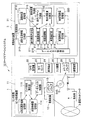
図1は、本発明の実施形態に係るカーナビゲーションシステムの機能ブロックの構成の例を示した図である。図1に示すように、カーナビゲーションシステム10は、交通情報センタなどに設置されるセンタ装置1および乗用車などの車両に搭載される車載端末装置2を含んで構成される。このとき、センタ装置1と車載端末装置2との間の情報転送は、DVD(Digital Versatile Disk)5などの可搬記憶メディア、電話回線やインターネットなどからなる通信ネットワーク3、携帯電話網の基地局4などを介して行われる。
(1. Overall configuration of car navigation system)
FIG. 1 is a diagram showing an example of a functional block configuration of a car navigation system according to an embodiment of the present invention. As shown in FIG. 1, the
ここで、センタ装置1は、汎用的な情報処理装置であるセンタ処理装置11、通信ネットワーク3に接続されたルータなどからなる通信装置12、DVD5など可搬記憶メディアのリーダ・ライタからなるメディアドライブ13などを含んで構成される。
Here, the
センタ処理装置11は、ハードウエアの実体として、情報処理の実行主体となるCPU(Central Processing Unit:図示省略)、情報処理のプログラムや様々な情報を記憶する記憶装置(半導体メモリ、ハードディスク装置など:図示省略)などを含んで構成される。
The
センタ処理装置11は、また、その機能ブロックとして、図1に示すように、リンク形状集約部111、データ入出力制御部112、3次元道路地図記憶部113、地形特徴量記憶部114などを含んで構成される。
As shown in FIG. 1, the
この場合、リンク形状集約部111は、3次元道路地図記憶部113に記憶されている3次元道路地図から、各道路リンクのアップダウンなどの3次元形状情報を取得し、その道路リンクの3次元形状に沿って車両が走行したとするときに、その走行とともに変化する車両のエネルギーの変化量を算出するエネルギー変化量算出手段として動作し、さらに、その車両のエネルギーの変化量に基づき地形特徴量を算出し、算出した地形特徴量を地形特徴量記憶部114に保存する。なお、リンク形状集約部111における詳細な処理については、別途、後記する。
In this case, the link
データ入出力制御部112は、通信装置12やメディアドライブ13に対する情報の入出力を制御する。本実施形態に即していえば、データ入出力制御部112は、地形特徴量記憶部114に記憶されている地形特徴量を、通信装置12を介し、さらに、通信ネットワーク3、基地局4などを介して、車載端末装置2へ送信する、または、メディアドライブ13を介して、地形特徴量をDVD5などの可搬記憶メディアに書き込む。
The data input /
これらリンク形状集約部111およびデータ入出力制御部112の機能は、センタ処理装置11がそのCPUにより、その記憶装置にあらかじめ格納された所定のプログラムを実行することによって実現される。また、3次元道路地図記憶部113および地形特徴量記憶部114は、その記憶装置上に構成される。
The functions of the link
次に、車載端末装置2は、汎用的な情報処理装置であるカーナビ処理装置21、GPS(Global Positioning System)衛星電波を受信して現在位置を測位するGPS受信機22、ジャイロなどからなる方向センサ23、LCD(Liquid Crystal Display)などからなる表示装置24、タッチパネルやリモコン装置などからなる入力装置25、DVD5など可搬記憶メディアのリーダ・ライタからなるメディアドライブ26、携帯電話機などからなる通信装置27を含んで構成される。
Next, the in-
カーナビ処理装置21は、ハードウエアの実体として、情報処理の実行主体となるCPU(図示省略)、情報処理のプログラムや様々な情報を記憶する記憶装置(半導体メモリ、ハードディスク装置など:図示省略)を含んで構成される。
The car
カーナビ処理装置21は、また、その機能ブロックとして、図1に示すように、旅行時間予測部211、経路探索部212、経路誘導部213、車種選択部214、燃料消費予測部215、データ入出力制御部216、統計交通情報記憶部217、道路地図記憶部218、車種特性量記憶部219、地形特徴量記憶部220などを含んで構成される。これらの機能ブロックの詳細については、別途、後記する。
As shown in FIG. 1, the car
なお、これら旅行時間予測部211、経路探索部212、経路誘導部213、車種選択部214、燃料消費予測部215およびデータ入出力制御部216の機能は、カーナビ処理装置21がそのCPUにより、その記憶装置にあらかじめ格納された所定のプログラムを実行することによって実現される。また、統計交通情報記憶部217、道路地図記憶部218、車種特性量記憶部219および地形特徴量記憶部220は、その記憶装置上に構成される。
The functions of these travel
(2.センタ装置1の動作)
続いて、図2ないし図6を参照して、センタ処理装置11におけるリンク形状集約処理について説明する。リンク形状集約処理は、リンク形状集約部111の処理として実行され、情報量の大きい3次元道路地図を、情報量の小さい地形特徴量データに集約する処理である。
(2. Operation of center device 1)
Subsequently, the link shape aggregation processing in the
ここで、図2は、3次元道路地図記憶部113に記憶される3次元道路地図のレコード構成の例を示した図、図3は、複数の小区間に分割された道路リンクの高さ方向のリンク形状の例を示した図、図4は、リンク形状集約処理の概念を説明するための(a)力学エネルギー変化量、(b)小区間分類、(c)地形特徴量の例を示した図、図5は、リンク形状集約処理の処理フローの例を示した図、図6は、地形特徴量記憶部114に記憶される地形特徴量のレコードの構成の例を示した図である。
Here, FIG. 2 is a diagram showing an example of the record configuration of the 3D road map stored in the 3D road map storage unit 113, and FIG. 3 is the height direction of the road link divided into a plurality of small sections. FIG. 4 shows an example of the link shape of FIG. 4, and FIG. 4 shows an example of (a) dynamic energy change amount, (b) small section classification, and (c) topographic feature amount for explaining the concept of link shape aggregation processing. FIG. 5 is a diagram illustrating an example of a processing flow of link shape aggregation processing, and FIG. 6 is a diagram illustrating an example of a configuration of a terrain feature quantity record stored in the terrain feature
3次元道路地図は、道路リンクの3次元の位置および形状を表した情報である。3次元道路地図では、各道路リンクの位置および形状は、その道路リンクに含まれる複数の点列の3次元座標(X,Y,Z)によって表現される。従って、直線で一定の勾配を有する道路リンクは、リンクの始端および終端の座標だけで表すことができる。一方、道路リンクの途中に屈曲点があったり、勾配の変化点があったりした場合には、その道路リンクの途中に補間点が設けられる。 The three-dimensional road map is information representing the three-dimensional position and shape of the road link. In the three-dimensional road map, the position and shape of each road link are expressed by the three-dimensional coordinates (X, Y, Z) of a plurality of point sequences included in the road link. Therefore, a road link having a straight line and a constant gradient can be expressed only by the coordinates of the start and end of the link. On the other hand, when there is an inflection point in the middle of a road link or there is a gradient change point, an interpolation point is provided in the middle of the road link.
一般に、道路リンクの途中に設けられる補間点の数やその間隔は任意であり、実際の道路の3次元形状を忠実に表現できるものであればよい。すなわち、直線形状の道路リンクには、補間点は設ける必要がなく、曲率の大きい道路には、狭い間隔(例えば、10m間隔)で補間点を設けてもよい。一般には、1つの道路リンクは、少なくとも始端および終端を含む2以上の点列の3次元座標によって表される。 In general, the number of interpolation points provided in the middle of the road link and the interval between them are arbitrary, and any one that can faithfully represent the actual three-dimensional shape of the road is acceptable. That is, it is not necessary to provide interpolation points for straight road links, and interpolation points may be provided at narrow intervals (for example, at intervals of 10 m) on roads with a large curvature. In general, one road link is represented by three-dimensional coordinates of two or more point sequences including at least a starting end and a terminal end.
図2に示すように、3次元道路地図のレコードは、リンクID、補間点番号、経度、緯度、高度を含んで構成され、その1つのレコードが、各道路リンクの始端および終端を含む各補間点の座標を表したものとなっている。 As shown in FIG. 2, the record of the three-dimensional road map includes a link ID, an interpolation point number, a longitude, a latitude, and an altitude, and that one record includes each interpolation including the start and end of each road link. It shows the coordinates of the points.
ここで、リンクIDは、各道路リンクに付された識別番号であり、車載端末装置2の道路地図記憶部218に記憶された2次元の道路地図において、各道路リンクに付された識別番号と同じものである。なお、道路リンクは、同じ道路区間であっても、上り線および下り線方向でそれぞれ別に定義されているものとする。また、補間点番号は、補間点を識別する番号である。ここでは、道路リンクの始端および終端も補間点とみなされ、その補間点番号は、始端を「1」とし、終端までの補間点の点列に対し、昇順の番号が付されている。また、経度、緯度および高度は、各補間点の3次元の位置座標(X,Y,Z)を表した情報である。
Here, the link ID is an identification number assigned to each road link. In the two-dimensional road map stored in the road
続いて、リンク形状集約処理の原理について説明する。 Next, the principle of link shape aggregation processing will be described.
図3に示すように、道路リンクは、一般には、補間点により複数の小区間に分割され、それぞれの小区間は、直線で近似される。燃料消費量を考える場合、道路の高低差や勾配が燃料消費量に大きな影響を与えるので、ここでは、道路リンクの各小区間は、リンク始端からの距離と高度との関係として表されている。 As shown in FIG. 3, the road link is generally divided into a plurality of small sections by interpolation points, and each small section is approximated by a straight line. When considering fuel consumption, the difference in road height and slope have a large effect on fuel consumption, so here, each small section of the road link is represented as a relationship between the distance from the link start and the altitude. .
ところで、車両の走行モードは、加速走行、一定速度走行および減速走行の3つのいずれかの走行モードに分類される。ちなみに、平坦な(勾配がゼロ)道路を加速走行する場合には、車両の運動エネルギーを増加させる必要があるので、車両の燃料消費量は大きくなる。それに対し、一定速度走行の場合には、車両の転がり摩擦に打ち勝つだけのエネルギーを供給すればよいので、燃料消費量は少なくて済む。また、減速走行の場合には、車両にエネルギーを供給する必要がないので、燃料は消費されない。 By the way, the traveling mode of the vehicle is classified into any one of three traveling modes of acceleration traveling, constant speed traveling, and deceleration traveling. Incidentally, when accelerating traveling on a flat road (with zero gradient), it is necessary to increase the kinetic energy of the vehicle, so that the fuel consumption of the vehicle increases. On the other hand, when the vehicle travels at a constant speed, it is sufficient to supply energy that can overcome the rolling friction of the vehicle. In addition, in the case of decelerating traveling, no fuel is consumed because there is no need to supply energy to the vehicle.
また、車両が坂道を走行する場合に、その燃料消費を計算しようとすると、さらに、位置エネルギーを考慮する必要がある。そこで、ここでは、車両が所定の勾配を有する小区間全域を走行したとき、力学エネルギーがどのように変化するかを考えるために、力学エネルギー変化量Mを、次の(式1)により定義する。
M=FR+ΔP+ΔM (式1)
ここで、FR:摩擦損失エネルギー
ΔP:位置エネルギーの変化量
ΔM:運動エネルギーの変化量
Further, when the vehicle travels on a slope, if it is attempted to calculate the fuel consumption, it is necessary to further consider the potential energy. Therefore, here, in order to consider how the dynamic energy changes when the vehicle travels in the entire small section having a predetermined gradient, the dynamic energy change amount M is defined by the following (Equation 1). .
M = FR + ΔP + ΔM (Formula 1)
Where FR: friction loss energy
ΔP: change in potential energy
ΔM: Change in kinetic energy
なお、(式1)の力学エネルギー変化量Mは、車両の重量(車重)で規格化されたもの、すなわち、車両の単位重量あたりの力学エネルギーであるとする。また、その計算で用いられる摩擦係数、加減速時の加速度などは、路面、車両、ドライバの特性の依存を考慮せず、平均化された値であるとし、それらの値は、車両の設計情報、走行試験などにより取得可能であるとする。また、空気抵抗は、走行速度に依存するが、ここでは、その空気抵抗を無視する。また、車両の加速時および減速時における加速度は、それぞれ等しいものとする。 Note that the amount of change in mechanical energy M in (Equation 1) is normalized by the weight of the vehicle (vehicle weight), that is, the dynamic energy per unit weight of the vehicle. Also, the friction coefficient used in the calculation, acceleration during acceleration / deceleration, etc. are average values without considering the dependence of the road surface, vehicle, and driver characteristics, and these values are the vehicle design information. It is assumed that it can be acquired by a running test or the like. The air resistance depends on the traveling speed, but here, the air resistance is ignored. Further, it is assumed that the acceleration at the time of acceleration and deceleration of the vehicle is equal.
リンク形状集約処理では、各小区間を、車両が加速走行、一定速度走行および減速走行した場合のそれぞれについて、力学エネルギー変化量Mを求める。図3に示した道路リンクの小区間1−5について、その力学エネルギー変化量Mを計算した結果の例を示したものが、図4(a)である。 In the link shape aggregation processing, the dynamic energy change amount M is obtained for each of the small sections when the vehicle travels at an accelerated speed, a constant speed, and a reduced speed. FIG. 4A shows an example of a result of calculating the dynamic energy change amount M for the small section 1-5 of the road link shown in FIG.
図4(a)で、「摩擦+位置」の欄は、(式1)の「FR+ΔP」の部分のエネルギーを表したもの、また、「加速走行」、「一定速度走行」および「減速走行」の各欄は、それぞれ、車両が加速走行、一定速度走行および減速走行したときの(式1)の値(力学エネルギー変化量M)を表したものである。 In FIG. 4A, the “friction + position” column represents the energy of the “FR + ΔP” portion of (Equation 1), and “accelerated traveling”, “constant speed traveling”, and “decelerated traveling”. Each column of (1) represents the value (dynamic energy change amount M) of (Expression 1) when the vehicle travels at an accelerated speed, at a constant speed, and at a reduced speed.
なお、加速走行時および減速走行時の力学エネルギー変化量Mは、その加速度をG、小区間の長さをLとすれば、M=G×Lと表される。前記したように、本実施形態では、加速走行時および減速走行時における加速度Gの大きさ(絶対値)は同じあるとしているので、GをG>0の一定の値であるとすれば、その力学エネルギー変化量Mは、加速時に、M=+G×L、減速時に、M=−G×Lとなる。 The dynamic energy change amount M during acceleration traveling and deceleration traveling is expressed as M = G × L, where G is the acceleration and L is the length of the small section. As described above, in the present embodiment, since the magnitude (absolute value) of acceleration G during acceleration traveling and deceleration traveling is the same, if G is a constant value of G> 0, The mechanical energy change amount M is M = + G × L during acceleration and M = −G × L during deceleration.
図4(a)において、例えば、図3に示した勾配のない小区間1および2では、「摩擦+位置」の欄のエネルギーは、ΔP=0であるため小さいが、正の勾配を有する小区間3では、「摩擦+位置」の欄のエネルギーは、ΔPの分だけ大きくなり、負の勾配を有する小区間4および5では、ΔPが負になるので、「摩擦+位置」の欄のエネルギーは、負になる場合が生じる。
In FIG. 4A, for example, in the
「摩擦+位置」の欄のエネルギーが負となる場合には、その勾配により、減速走行時だけでなく、一定速度走行時にも力学エネルギー変化量Mが負になる場合(小区間4)がある。この場合には、車両が一定速度走行するときでも、車両にエネルギーを供給する必要がなく、つまり、車両の燃料消費がゼロとなる。さらに、加速走行時にも力学エネルギー変化量Mが負になる場合(小区間5)が生じる。そのような小区間では、加速走行時にも車両の燃料消費がゼロとなる。 When the energy in the column of “Friction + Position” is negative, there is a case where the mechanical energy change amount M becomes negative (small section 4) not only during deceleration traveling but also during constant speed traveling due to the gradient. . In this case, even when the vehicle travels at a constant speed, it is not necessary to supply energy to the vehicle, that is, the fuel consumption of the vehicle becomes zero. Furthermore, there is a case where the dynamic energy change amount M becomes negative even during acceleration travel (small section 5). In such a small section, fuel consumption of the vehicle becomes zero even during acceleration traveling.
そこで、小区間を、車両の走行モードそれぞれについての燃料消費の有無によって、図4(b)のように分類することができる。ここで、分類Aは、いずれの走行モードでも燃料が消費されない小区間(小区間5)、例えば、加速走行時でさえも燃料が消費されないような急な下り坂である。分類Bは、加速走行時には燃料が消費されるが、一定速度走行時および減速走行時には燃料が消費されない小区間(小区間4)、例えば、緩い下り坂である。分類Cは、一定速度走行時および加速走行時には燃料が消費されるが、減速走行時には燃料が消費されない小区間(小区間1,2)、例えば、平坦な道路、極めて緩い下り坂または緩い上り坂である。分類Dは、いずれの走行モードでも燃料が消費される小区間(小区間3)、例えば、減速走行時でさえも燃料が消費される急な登り坂である。
Therefore, the small sections can be classified as shown in FIG. 4B by the presence or absence of fuel consumption for each of the vehicle driving modes. Here, the classification A is a small section (small section 5) in which fuel is not consumed in any travel mode, for example, a steep downhill where fuel is not consumed even during acceleration travel. Class B is a small section (small section 4) in which fuel is consumed during acceleration traveling but no fuel is consumed during constant speed traveling and deceleration traveling, for example, a gentle downhill. Category C is a small section (
図4(a)の「分類」欄には、図3に示した道路リンクの各小区間について、以上のようにして分類した分類結果の例が示されている。 In the “classification” column of FIG. 4A, examples of classification results obtained by classifying the small sections of the road link shown in FIG. 3 as described above are shown.
ところで、図4(a)において、「摩擦+位置」の欄のエネルギーは、小区間の3次元形状によって定まる値である。すなわち、摩擦損失エネルギーFRは、走行距離、つまり、小区間の長さによって定まり、位置エネルギーの変化量ΔPは、小区間の両端の高低差によって定まる。従って、それぞれの小区間において、「摩擦+位置」のエネルギー変化量を考えた場合、これらは小区間の三次元形状によって定まる値であり、車両の走行の仕方に依存しない。そのため、「摩擦+位置」の欄のエネルギーは、その小区間の地形特徴量ということができる。そこで、「摩擦+位置」の欄のエネルギーを、以下、「小区間の地形特徴量」と呼ぶ。 Incidentally, in FIG. 4A, the energy in the column of “friction + position” is a value determined by the three-dimensional shape of the small section. That is, the friction loss energy FR is determined by the travel distance, that is, the length of the small section, and the positional energy change ΔP is determined by the height difference between both ends of the small section. Therefore, when the amount of energy change of “friction + position” is considered in each small section, these are values determined by the three-dimensional shape of the small section, and do not depend on how the vehicle travels. Therefore, it can be said that the energy in the column of “friction + position” is the topographic feature amount of the small section. Therefore, the energy in the column of “friction + position” is hereinafter referred to as “small terrain feature quantity”.
また、「摩擦+位置」のエネルギー変化量を求める際には、車重について規格化して単位質量当たりのエネルギー変化量を求め、摩擦係数についても、燃料消費予測の対象として考える車種の平均的な摩擦係数を用いている。従って、このようにして求められる小区間の地形特徴量は、全対象車種で共通のものとすることができ、車種毎にデータを作成する必要がなくなる。 In addition, when calculating the amount of energy change for “friction + position”, the vehicle weight is normalized to determine the amount of energy change per unit mass, and the friction coefficient is also the average of the vehicle types that are considered as targets for fuel consumption prediction. The coefficient of friction is used. Therefore, the terrain feature amount of the small section obtained in this way can be common to all target vehicle types, and it is not necessary to create data for each vehicle type.
次に、リンク形状集約処理では、その小区間の地形特徴量を用いて、複数の小区間からなる道路リンクの地形特徴量として、4つの特徴量MA,MB,MCおよびMDを次のように定義する。
Mi=(分類iに属する小区間の地形特徴量の総和) (式2)
ここで、i=A,B,C,D
Next, a link shape compression process, using geographic characteristic values of the small sections, as geometry parameters of the road link comprising a plurality of small sections, four feature amounts M A, M B, the M C and M D Define as follows.
Mi = (sum of topographic feature quantities of small sections belonging to category i) (Formula 2)
Where i = A, B, C, D
図4(c)の「小区間の地形特徴量の総和」の欄は、図4(a)における各分類A−Dに属する小区間について、小区間の地形特徴量の総和を計算したものである。例えば、図4(c)の「分類C」の「小区間の地形特徴量の総和」の欄は、図4(a)で「分類C」に分類された「小区間1および2」の「摩擦+位置」の欄のエネルギーの総和を計算したものである。
The column of “Summary of Topographic Feature Amounts in Small Sections” in FIG. 4C is obtained by calculating the sum of topographic feature quantities in the small sections for the small sections belonging to the respective classifications AD in FIG. is there. For example, the column “Summary of topographic feature quantities in small sections” of “Category C” in FIG. 4C indicates “
詳細は、後記するところによるが、これらの地形特徴量MA,MB,MCおよびMDと、車重など車両の特性量と、を用いることにより、道路リンクの燃料消費量を計算することができる。すなわち、本実施形態では、3次元道路地図に代えて、道路リンクの地形特徴量を用いることにより、道路リンクの燃料消費量の計算が可能になったことを意味する。つまり、各道路リンクの3次元の位置情報によって表される3次元のリンク形状は、地形特徴量MA,MB,MCおよびMDに集約されたことになる。 For more information, depending on the place which will be described later, these geographic characteristic values M A, M B, and M C and M D, and characteristics of the vehicle such as vehicle weight, by using, to calculate the fuel consumption of a road link be able to. In other words, in this embodiment, it is possible to calculate the fuel consumption of the road link by using the terrain feature quantity of the road link instead of the three-dimensional road map. That is, three-dimensional link shapes represented by the three-dimensional position information of each road link, the geographic characteristic value M A, M B, will have been aggregated into M C and M D.
なお、図4(b)に示したように、分類Aの小区間では、加速走行、一定速度走行および減速走行のいずれの場合にも、燃料が消費されない。従って、その地形特徴量MAは、その後の燃料消費量の計算において使用されることがない。そのため、図4(c)では、「地形特徴量」の欄に「MA」が記載されず、「−」と記載されている。 Note that, as shown in FIG. 4B, in the small section of category A, fuel is not consumed in any of acceleration traveling, constant speed traveling, and deceleration traveling. Therefore, the geometry parameter M A is never used in the calculation of the subsequent fuel consumption. Therefore, in FIG. 4C, “M A ” is not described in the “terrain feature value” column, and “−” is described.
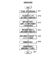
続いて、以上の説明をまとめる形で、図5を参照して、センタ処理装置11のリンク形状集約部111におけるリンク形状集約処理について説明する。リンク形状集約処理は、図5に示すように、3次元道路地図113に含まれる道路リンクすべてについてのループ処理として実行される(ステップS1)。
Next, the link shape aggregation processing in the link
そこで、センタ処理装置11のCPU(以下、単に、CPUという)は、リンクIDを設定して、3次元道路地図113から、そのリンクIDを有するリンクデータを読み込む(ステップS2)。ここで、リンクデータは、3次元道路地図113におけるレコードを意味する。 Therefore, the CPU of the center processing device 11 (hereinafter simply referred to as CPU) sets a link ID and reads link data having the link ID from the three-dimensional road map 113 (step S2). Here, the link data means a record in the three-dimensional road map 113.
次に、CPUは、読み込んだリンクデータから、例えば、各補間点におけるリンク始端からの距離と高度のデータからなる小区間データを生成し(ステップS3)、図4(a)に示したようにそれぞれの走行モードごとに力学エネルギー変化量を算出、つまり、小区間の地形特徴量を算出する(ステップS4)。さらに、CPUは、その算出した力学エネルギー変化量に基づき、当該小区間を分類する(ステップS5)。 Next, the CPU generates, for example, small section data including the distance from the link start end and the altitude data at each interpolation point from the read link data (step S3), as shown in FIG. The dynamic energy change amount is calculated for each driving mode, that is, the terrain feature amount of the small section is calculated (step S4). Further, the CPU classifies the small section based on the calculated dynamic energy change amount (step S5).
次に、CPUは、各小区間の地形特徴量に基づき、道路リンクの地形特徴量MB,MCおよびMDを生成し(ステップS6)、生成した地形特徴量MB,MCおよびMDを地形特徴量記憶部114に保存する(ステップS7)。そして、CPUは、すべての道路リンクについてステップS1以下のループ処理を実行したか否かを判定し、ループ処理を実行していた場合には、そのループ処理を終了する(ステップS8)。 Next, the CPU generates terrain feature quantities M B , M C and M D of road links based on the terrain feature quantities of each small section (step S6), and the generated terrain feature quantities M B , M C and M D is stored in the terrain feature data storage unit 114 (step S7). Then, the CPU determines whether or not the loop processing of step S1 and subsequent steps has been executed for all road links. If the loop processing has been executed, the loop processing is terminated (step S8).
地形特徴量記憶部114に保存された地形特徴量は、図6に示すように、それぞれのリンクごとにMB,MCおよびMDの3つのデータにより構成される。この地形特徴量の構成を、図2に示した3次元道路地図のデータと比較すると、地形特徴量3次元道路地図が、いかに小さなデータに集約されたかが分る。
As shown in FIG. 6, the terrain feature quantity stored in the terrain feature
なお、地形特徴量記憶部114に保存された地形特徴量は、データ入出力制御部112の処理によりメディアドライブ13を介してDVD5などの可搬記憶メディアに書き込まれたり、通信装置12、通信ネットワーク3などを介して、車載端末装置2へ送信されたりする。
Note that the terrain feature quantity stored in the terrain feature
(3.車載端末装置2の動作)
図7ないし図9を参照して、カーナビ処理装置21における車種選択処理について説明する。車種選択処理は、車種選択部214の処理として実行され、当該車載端末装置2が搭載されている車両の車種を選択する。
(3. Operation of in-vehicle terminal device 2)
With reference to FIG. 7 thru | or FIG. 9, the vehicle type selection process in the car
ここで、図7は、車種特性量記憶部219に記憶される車種特性量データの構成の例を示した図、図8は、車種選択処理の処理フローの例を示した図、図9は、表示装置24に表示される車種選択画面の例を示した図である。
Here, FIG. 7 is a diagram showing an example of the configuration of the vehicle type characteristic amount data stored in the vehicle type characteristic
図7に示すように、車種特性量データは、車種ID、車種名、車重W、エンジン基礎消費量F、力学エネルギー当量E、空気抵抗係数kなどから構成される。 As shown in FIG. 7, the vehicle type characteristic amount data includes a vehicle type ID, a vehicle type name, a vehicle weight W, an engine basic consumption F, a mechanical energy equivalent E, an air resistance coefficient k, and the like.
ここで、エンジン基礎消費量Fは、内部抵抗に抗してエンジン回転を維持するために消費される単位時間当たりの燃料消費量である。また、力学エネルギー当量Eは、所定の力学エネルギーを得るために必要な燃料消費量であり、燃料消費量をqとし、力学エネルギーをHとしたとき、E=q/Hで与えられる量である。また、空気抵抗係数kは、車輌のCd値、前方投影面積Aおよび空気密度ρを用いて、k=Cd×ρ×A/2により定義される値である。 Here, the engine basic consumption F is a fuel consumption per unit time consumed for maintaining the engine rotation against the internal resistance. Further, the mechanical energy equivalent E is a fuel consumption amount required to obtain a predetermined mechanical energy, and is an amount given by E = q / H, where q is the fuel consumption amount and H is the dynamic energy. . The air resistance coefficient k is a value defined by k = Cd × ρ × A / 2 using the Cd value of the vehicle, the forward projection area A, and the air density ρ.
なお、車種特性量データは、データ入出力制御部216の処理により、DVD5などの可搬記憶メディアのメディアドライブ26、または、通信装置27を介して、あらかじめ外部から入力され、車種特性量記憶部219に記憶されているものとする。
The vehicle type characteristic amount data is input in advance from the outside via the media drive 26 of the portable storage medium such as the
ドライバは、車載端末装置2から燃費最小経路の提供を受けるには、自車の車種を選択しておく必要がある。そこで、ドライバが入力装置25などから車種選択開始の指示情報を入力すると、カーナビ処理装置21のCPU(以下、単に、CPUという)は、図8に示す車種選択処理を開始する。
In order to receive the provision of the minimum fuel consumption route from the in-
車種選択処理において、CPUは、まず、車種特性量記憶部219から車種特性量のデータを読み込み(ステップS11)、図9に示すような車種選択画面241を表示装置24に表示する(ステップS12)。その車種選択画面241には、車種名、メーカ名、モデル名、年式などの一覧表が表示される。その一覧表にはドライバが車種を選択するためのチェック欄2411が設けられている。そこで、ドライバが入力装置25を介して自車の車種を選択すると、CPUは、その車種選択情報を入力して(ステップS13)、その入力した車種選択情報により指定される車種の車種特性量を、自車特性量として記憶装置に記憶する(ステップS14)。
In the vehicle type selection process, the CPU first reads vehicle type characteristic amount data from the vehicle type characteristic amount storage unit 219 (step S11), and displays a vehicle
なお、車種特性量における車重Wは、車両本来の車体重量にドライバの重量として成人の平均体重を加算したものが設定されているものとする。あるいは、搭乗人員入力画面などを設けることにより、ドライバが必要に応じて搭乗人員や荷物の重量を直接数値として入力し、車重Wを修正できるようにしてもよい。また、車両に車重を検知するセンサが備わっている場合は、そのセンサの出力を車重Wとしてもよい。 It is assumed that the vehicle weight W in the vehicle type characteristic amount is set by adding the average body weight of an adult as the weight of the driver to the original body weight of the vehicle. Alternatively, by providing a crew member input screen or the like, the driver may input the weight of the crew member or the baggage directly as a numerical value so that the vehicle weight W can be corrected. Further, when the vehicle has a sensor for detecting the vehicle weight, the output of the sensor may be the vehicle weight W.
以上の車種選択処理により、車載端末装置2は、様々な車種に対して、より精度の高い燃費最小経路をドライバに提供できるようになる。
Through the above vehicle type selection process, the in-
続いて、図10ないし図13を参照して、カーナビ処理装置21における燃料消費予測処理について説明する。燃料消費予測処理は、燃料消費予測部215の処理として実行され、道路リンクにおける自車の燃料消費量を予測する。
Next, the fuel consumption prediction process in the car
ここで、図10は、統計交通情報記憶部217に記憶された統計交通情報のレコード構成の例を示した図、図11は、燃料消費予測処理に含まれる走行パターン予測処理の処理フローの例を示した図、図12は、道路リンクにおける車両の走行パターンの例を示した図、図13は、燃料消費予測処理に含まれる燃料消費量計算処理の処理フローの例を示した図である。
Here, FIG. 10 is a diagram showing an example of a record configuration of statistical traffic information stored in the statistical traffic
統計交通情報は、図10に示すように、各道路リンクにおける過去の旅行時間の統計値を、日種(平日、休日など)別や時間帯別に、統計交通情報記憶部217に記憶した情報である。なお、統計交通情報は、あらかじめ、データ入出力制御部216の処理により、DVD5などの可搬記憶メディアのメディアドライブ26、または、通信装置27を介して外部から入力され、統計交通情報記憶部217に記憶されているものとする。
As shown in FIG. 10, the statistical traffic information is information stored in the statistical traffic
次に、ドライバにより入力装置25を介して燃費最小経路探索の指示情報が入力されたときなどには、カーナビ処理装置21のCPUは、旅行時間予測部211の処理として、統計交通情報記憶部217に記憶された統計交通情報や現在の交通情報に基づき、前記の指示情報により指定された日種および時間帯におけるリンク旅行時間を予測する。その予測方法については、様々な公知技術があるので、ここでは、その説明を割愛する。なお、リンク旅行時間の最も簡単な予測方法によれば、指定された日種および時間帯における統計交通情報に記憶されているリンク旅行時間を、そのまま予測値とすることができる。
Next, when the instruction information for searching the minimum fuel consumption route is input through the
続いて、CPUは、走行パターン予測部2151の処理として、図11に示す走行パターン予測処理を開始する。まず、CPUは、旅行時間予測部211によって予測されたリンク旅行時間Tを取得し(ステップS21)、さらに、道路地図記憶部218から予測の対象となる道路リンクのリンク長Lを取得する(ステップS22)。
Subsequently, the CPU starts a travel pattern prediction process shown in FIG. 11 as a process of the travel
次に、CPUは、渋滞予測処理を実行する(ステップS23)。渋滞予測処理においてCPUは、ステップS21で取得したリンク旅行時間Tと、ステップS22で取得したリンク長Lと、に基づき、その道路リンクにおける車両の平均速度Va(=L/T)を算出し、その平均速度Vaに基づき、道路リンクの渋滞度Jを算出する。なお、渋滞度Jは、一般道では、例えば、Va≧30km/hのときJ=1、30km/h>Va≧10km/hのときJ=2、10km/h>VaのときJ=3と定める。同様に、高速道路では、渋滞度Jは、例えば、Va≧60km/hのときJ=1、60km/h>Va≧40km/hのときJ=2、40km/h>VaのときJ=3と定める。 Next, the CPU executes a traffic jam prediction process (step S23). In the traffic jam prediction process, the CPU calculates an average speed Va (= L / T) of the vehicle on the road link based on the link travel time T acquired in step S21 and the link length L acquired in step S22. Based on the average speed Va, the degree J of road link congestion is calculated. The congestion degree J is, for example, J = 1 when Va ≧ 30 km / h, J = 2 when Va ≧ 30 km / h, J = 2 when 30 km / h> Va ≧ 10 km / h, and J = 3 when 10 km / h> Va. Determine. Similarly, on a highway, the degree of congestion J is, for example, J = 1 when Va ≧ 60 km / h, J = 2 when 60 km / h> Va ≧ 40 km / h, and J = 3 when 40 km / h> Va. It is determined.
次に、CPUは、加減速予測処理を実行する(ステップS24)。加減速予測処理は、各道路リンクにおける車両の加減速の回数Nを予測する処理である。ここでは、加減速の回数NをN=T/Cの式により予測する。この式で、Cは、道路種別により決まる定数であるとする。ちなみに、一般道では信号機などの影響を多く受けるので、高速道路に比べ、加減速が多く発生する。従って、一般道でのCをCA、高速道路でのCをCBとすると、CA<CBとなる。 Next, the CPU executes acceleration / deceleration prediction processing (step S24). The acceleration / deceleration prediction process is a process for predicting the number N of vehicle acceleration / deceleration on each road link. Here, the number of times of acceleration / deceleration N is predicted by the equation N = T / C. In this equation, C is a constant determined by the road type. Incidentally, general roads are much affected by traffic lights and the like, and therefore more acceleration / deceleration occurs than on highways. Therefore, when C on a general road is C A and C on a highway is C B , C A <C B.
このN=T/Cの式は、リンク旅行時間Tが長くなるほど、そのリンク旅行時間Tに応じて速度の揺らぎや信号機の影響が多くなるため、加減速が多く発生することを表している。また、同じ道路リンクであっても、リンク旅行時間Tが大きくなるほど、つまり、渋滞度が高まるほど、加減速が多く発生することをも表している。 The equation N = T / C indicates that the longer the link travel time T, the greater the speed fluctuation and the influence of traffic lights depending on the link travel time T, so that more acceleration / deceleration occurs. In addition, even for the same road link, the longer the link travel time T, that is, the higher the degree of traffic congestion, the more acceleration / deceleration occurs.
なお、ここでは、リンク旅行時間Tでのみ、加減速の回数Nを予測しているが、この予測された加減速の回数Nを、3次元道路地図における道路リンクの補間点の数によって、補正するようにしてもよい。すなわち、補間点が設けられることが多い道路リンクの屈曲点、カーブ、勾配の変化点などにおいては、加減速されることが多いので、加減速の回数Nを補間点の数や密度に応じて増減させてもよい。 Here, the number of accelerations / decelerations N is predicted only in the link travel time T, but the predicted number of accelerations / decelerations N is corrected by the number of interpolation points of road links in the three-dimensional road map. You may make it do. That is, at the bending point, curve, and slope change point of a road link where interpolation points are often provided, acceleration / deceleration is often performed, so the number of accelerations / decelerations N depends on the number and density of interpolation points. It may be increased or decreased.
次に、CPUは、加減速確率予測処理を実行する(ステップS25)。ここで、加減速確率とは、道路リンク内で加速走行した距離の割合PA、減速走行した距離の割合PDを意味している。従って、一定速度走行した距離の割合は、1-PA-PDとなる。 Next, the CPU executes acceleration / deceleration probability prediction processing (step S25). Here, the acceleration / deceleration probability means the ratio P A of the distance traveled by acceleration within the road link and the ratio P D of the distance traveled by deceleration. Accordingly, the ratio of the distance traveled at a constant speed is 1−P A −P D.
CPUは、当該リンクの渋滞度Jを求め、その渋滞度Jでの最高速度を、VMAXに設定する。ただし、その道路リンクに規制速度が設定されていた場合には、渋滞度Jでの最高速度または規制速度のうち小さい方をVMAXに設定する。例えば、当該リンクが一般道であり、Va=25km/h、規制速度=50km/hの場合には、渋滞度J=2となり、J=2における最高速度ステップは、ステップS23の説明で示したように30km/hであることから、VMAX=30km/hとなる。 The CPU obtains the traffic congestion degree J of the link and sets the maximum speed at the traffic congestion degree J to V MAX . However, if a regulated speed is set for the road link, the smaller of the maximum speed or the regulated speed at the congestion degree J is set to V MAX . For example, when the link is a general road, Va = 25 km / h, and restricted speed = 50 km / h, the degree of congestion J = 2, and the maximum speed step at J = 2 is shown in the description of step S23. Thus, V MAX = 30 km / h because of 30 km / h.
次に、CPUは、PAおよびPDを算出する。このとき、一定速度走行は、速度VMAXでの走行、加速走行は、その速度を速度0km/hから一定加速度Gで速度VMAXに加速するための走行、減速走行は、その速度を速度VMAXから一定加速度Gで速度0km/hに減速するための走行であるとする。なお、このGの値は、センタ処理装置11でのリンク形状集約処理(図5参照)で用いた加減速の加速度Gの値と同じであるとする。
Then, CPU calculates the P A and P D. At this time, the constant speed traveling is traveling at the speed V MAX and the acceleration traveling is traveling to accelerate the speed from the
例えば、一定速度走行している車両が、ある道路リンクで2回の加減速を繰り返した場合、走行速度とリンク始端からの距離との関係を示す走行パターンは、図12に示すようなパターンになる。ここでは、加減速の加速度は同じ値Gであるので、図12において、1回の加速または減速に要した距離LAは、それぞれ等しく(LA=A=B=C=D)、その距離LAは、LA=VMAX 2/2Gによって計算される。 For example, when a vehicle traveling at a constant speed repeats acceleration / deceleration twice on a certain road link, the traveling pattern indicating the relationship between the traveling speed and the distance from the link start end is a pattern as shown in FIG. Become. Here, the acceleration of deceleration is the same value G, 12, the distance L A required for acceleration or deceleration of the one, respectively equal (L A = A = B = C = D), the distance L A is calculated by L A = V MAX 2 / 2G.
そこで、CPUは、その距離LA、当該道路リンクのリンク長L、ステップS24で求めた加減速の回数Nを用い、PA=PB=LA×N/Lの式により、PAおよびPDを計算する。 Therefore, CPU, the distance L A, the link length of the road link L, using the number N of acceleration and deceleration calculated in step S24, the equation P A = P B = L A × N / L, P A and to calculate the P D.
また、車両が高速道路を順調走行する場合、図12に示した走行パターンのように、速度がVMAXと0km/hとを行き来するような加減速走行は発生しない。しかしながら、速度揺らぎの現象は見られるので、それを、速度VMAXと速度VLOWとを行き来する加減速走行とみなせば、高速道路の順調走行でも、図12に類似する走行パターンのモデルを適用することは可能である。 Further, when the vehicle travels smoothly on the highway, acceleration / deceleration traveling in which the speed goes back and forth between V MAX and 0 km / h does not occur as in the traveling pattern shown in FIG. However, since the phenomenon of speed fluctuation can be seen, if it is regarded as acceleration / deceleration traveling between the speed V MAX and the speed V LOW , the model of the traveling pattern similar to FIG. It is possible to do.
以上までの走行パターン予測処理(図11参照)により、加減速の回数N、最大走行速度VMAX、加減速確率PA,PDが算出されたことになる。以下、これらの情報を走行パターン予測情報と呼び、その走行パターン予測情報を燃料消費量計算部2152に引き渡す(図11、ステップS26)。 The number N of accelerations / decelerations, the maximum traveling speed V MAX , and acceleration / deceleration probabilities P A and P D are calculated by the above-described traveling pattern prediction process (see FIG. 11). Hereinafter, these pieces of information are referred to as travel pattern prediction information, and the travel pattern prediction information is delivered to the fuel consumption amount calculation unit 2152 (FIG. 11, step S26).
次に、CPUは、燃料消費量計算部2152の処理として、図13に示す燃料消費量計算処理を実行する。CPUは、まず、走行パターン予測部2151によって算出された走行パターン予測情報を取得し(ステップS31)、また、地形特徴量記憶部220から当該道路リンクの地形特徴量MB,MCおよびMDを取得する(ステップS32)。
Next, the CPU executes a fuel consumption calculation process shown in FIG. 13 as a process of the fuel
さらに、CPUは、車種選択部214により選択した自車の車種特性量の車重W、エンジン基礎消費量F、力学エネルギー当量E、空気抵抗係数kを用いて、次の計算式に基づき、燃料消費量予測値Qを算出する(ステップS33)。
Q=F×T+E×[W×{MB×PA+MC×(1−PA)+MD}
+EAIR+EACC] (式2)
Further, the CPU uses the vehicle weight W of the vehicle type characteristic amount selected by the vehicle
Q = F × T + E × [W × {M B × P A + M C × (1-P A) + M D}
+ E AIR + E ACC ] (Formula 2)
式2において、その第1項(F×T)は、エンジンの基礎消費量である。また、式2の[ ]内の各項のうち、地形特徴量MB,MCおよびMDに関する部分({ }内の各項)は、左側より順にそれぞれ加速走行による摩擦と位置エネルギーの損失、一定走行による摩擦と位置エネルギーの損失、および、減速走行による摩擦と位置エネルギーの損失である。また、式2の[ ]内の各項のうち、後部の2項は、それぞれ、EAIRが空気抵抗損失であり、EACCが加速に伴う運動エネルギーによる加速損失である。
In
なお、空気抵抗損失EAIRは、EAIR=k×VAVE 2×Lによって定義され、また、加速損失EACCは、加減速の回数Nを用いて、EACC=N×W×VMAX 2/2によって定義される。ここで、VAVEは、車両の平均走行速度である。 The air resistance loss E AIR is defined by E AIR = k × V AVE 2 × L, and the acceleration loss E ACC is calculated by using the number of times of acceleration / deceleration N, and E ACC = N × W × V MAX 2 Defined by / 2. Here, V AVE is the average traveling speed of the vehicle.
次に、CPUは、ステップS33で算出した燃料消費量予測値を経路探索部212に引き渡す(ステップS34)。 Next, the CPU delivers the predicted fuel consumption amount calculated in step S33 to the route search unit 212 (step S34).
カーナビ処理装置21のCPUは、以上に説明した走行パターン予測処理および燃料消費量計算処理により、指定された日種、時間帯および道路リンクに対する燃料消費量予測値Qを得ることができる。
The CPU of the car
以上、カーナビ処理装置21において燃料消費量予測値Qを得るまでの処理においては、3次元道路地図は必要でなく、代りに、各道路リンクの地形特徴量MB,MCおよびMDが利用されている。従って、カーナビ処理装置21は、3次元道路地図を保持する必要がないので、その分、カーナビ処理装置21の記憶装置の記憶容量は小さくて済む。また、燃料消費量予測値Qを計算するために、それぞれの道路リンクごとにわずか3つの地形特徴量MB,MCおよびMDだけしか使用していない。これは、燃料消費量計算処理の処理量も削減されていることを意味し、カーナビ処理装置21におけるCPUの計算処理負担が軽減されたことを意味する。
As described above, in the processing until the fuel consumption prediction value Q is obtained in the car
続いて、図14および図15を参照して、カーナビ処理装置21における経路探索処理および経路誘導処理について説明する。経路探索処理および経路誘導処理は、それぞれ、経路探索部212および経路誘導部213の処理として実行される。ここで、図14は、経路探索処理の処理フローの例を示した図、図15は、経路誘導処理によって表示装置24に表示される表示画面の例を示した図である。
Subsequently, a route search process and a route guidance process in the car
CPUは、ドライバにより入力装置25を介して燃費最小経路探索の指示情報が入力されたとき、または、燃費最小経路での経路誘導処理中にリルート要求が発生したときなどに、経路探索処理を開始する。CPUは、まず、入力装置25、GPS受信機22などから、目的地、自車位置の情報を取得し(ステップS41)、さらに、旅行時間予測部211から自車位置から目的地に到る経路の周辺道路のリンクの旅行時間の予測値を取得する(ステップS42)。
The CPU starts the route search process when the instruction information for searching the minimum fuel consumption route is input through the
次に、CPUは、燃料消費量計算部2152に対し、前記周辺道路についての道路リンクの燃料消費量の予測計算を要求し(ステップS43)、燃料消費量計算部2152により燃料消費量予測値が計算されると、燃料消費量計算部2152から燃料消費量予測値を取得し(ステップS44)、さらに、その燃料消費量予測値を用いて経路探索用のリンクコストを設定する(ステップS45)。
Next, the CPU requests the fuel
次に、CPUは、燃料消費量予測値が設定されたリンクコストに基づき、経路探索を実行し(ステップS46)、その経路探索結果を経路誘導部213に引き渡す(ステップS47)。なお、経路探索は、ダイクストラ法などの周知の経路探索のアルゴリズムを用いて行うことができ、そのとき得られる経路探索結果は、燃費最小経路である。 Next, the CPU executes a route search based on the link cost for which the predicted fuel consumption amount is set (step S46), and delivers the route search result to the route guide unit 213 (step S47). The route search can be performed using a known route search algorithm such as the Dijkstra method, and the route search result obtained at that time is the minimum fuel consumption route.
続いて、CPUは、経路誘導部213の処理に移行し、経路探索結果を表示装置24に表示する。その場合、表示装置24には、誘導経路として燃費最小経路だけを表示してもよいが、例えば、図15の誘導経路表示画面242に示すように、自車位置2421から目的地2422までの経路として、燃費最小経路2423と最短時間経路2424とを併せて表示するようにしてもよい。ただし、その場合には、経路探索部212の処理で、最短時間経路をも探索しておくものとする。
Subsequently, the CPU shifts to processing of the
また、その表示に際しては、誘導経路表示画面242内に経路の概要を示す表示ウィンドウ2425を設け、その表示ウィンドウ2425に、それぞれの経路についての燃料消費量や所要時間などを表示するようにしてもよい。さらに、その表示ウィンドウ2425内に、誘導経路を選択するチェックボックス2426を設け、ドライバが、誘導経路の種類を、適宜、選択できるようにしてもよい。
In addition, a
なお、図15では、燃費最小経路と最短時間経路とを表示装置24に表示するとしているが、最短時間経路に代えて最短距離経路を表示するとしてもよく、最短時間経路や最短距離経路に限らず、適宜、他のコスト関数で探索した複数の最小コスト経路を燃費最小経路と併せて表示してもよい。
In FIG. 15, the minimum fuel consumption route and the shortest time route are displayed on the
また、カーナビ処理装置21の構成としては、燃費最小経路を含め複数の最小コスト経路を探索し、その複数の経路を並列表示した上で、ドライバに誘導経路を選択させる(図15の場合)のではなく、あらかじめドライバに経路探索のコスト関数を選択させておき、そのコスト関数を最小にする経路のみを探索し、その探索した経路を誘導経路として表示するようにしてもよい。
Further, as a configuration of the car
なお、以上に説明した実施形態では、地形特徴量は、道路地図とは別個の情報として地形特徴量記憶部220(図1参照)に記憶されるものとしたが、道路地図記憶部218の道路リンク情報が地形特徴量を含む構成であってもよい。図16は、道路リンク情報が地形特徴量を含む場合の道路リンクデータのレコード構成の例を示した図である。図16に示すように、道路リンクデータは、道路リンクの位置および形状を表す座標点列、接続リンクの情報、リンクの属性情報など通常のリンクの属性データのほかに、地形特徴量を含んでいる。 In the embodiment described above, the terrain feature amount is stored in the terrain feature amount storage unit 220 (see FIG. 1) as information separate from the road map. The link information may include a terrain feature amount. FIG. 16 is a diagram illustrating an example of a record configuration of road link data when the road link information includes a terrain feature amount. As shown in FIG. 16, the road link data includes topographic feature quantities in addition to normal link attribute data such as a coordinate point sequence representing the position and shape of the road link, connection link information, and link attribute information. Yes.
この場合には、カーナビ処理装置21は、燃料消費予測部215などにおける処理において、道路地図記憶部218のデータと地形特徴量記憶部220のデータとの対応関係をとる必要がなくなるので、その関連する処理を高速化することができる。さらに、通信ネットワーク3やDVD5などを介して、地図および地形特徴量の情報を更新する場合、それらを同時に更新することができるようになるので、更新作業の手数が低減されることになる。
In this case, the car
1 センタ装置
2 車載端末装置
3 通信ネットワーク
4 基地局
5 DVD
10 カーナビゲーションシステム
11 センタ処理装置
12 通信装置
13 メディアドライブ
21 カーナビ処理装置
22 GPS受信機
23 方向センサ
24 表示装置
25 入力装置
26 メディアドライブ
27 通信装置
111 リンク形状集約部
112 データ入出力制御部
113 3次元道路地図記憶部
114 地形特徴量記憶部
211 旅行時間予測部
212 経路探索部
213 経路誘導部
214 車種選択部
215 燃料消費予測部
216 データ入出力制御部
217 統計交通情報記憶部
218 道路地図記憶部
219 車種特性量記憶部
220 地形特徴量記憶部
2151 走行パターン予測部
2152 燃料消費量計算部
2411 チェック欄
2421 自車位置
2422 目的地
2423 燃費最小経路
2424 最短時間経路
2425 表示ウィンドウ
2426 チェックボックス
1
DESCRIPTION OF
Claims (6)
前記道路地図データに含まれる各道路リンクについて、その道路リンクを分割した各小区間の高度情報を含む座標情報に基づき算出された各小区間の車両走行時の摩擦損失エネルギーおよび位置エネルギーの変化量を用いて、前記車両が前記小区間を加速走行、減速走行および一定速走行をそれぞれ行った場合の前記力学エネルギーの変化量を算出するとともに、そのそれぞれの場合の燃料消費の有無により、その小区間を分類し、前記道路リンクを構成するそれぞれの小区間の一定速走行時の前記力学エネルギー変化量を、前記小区間の分類ごとに集計して得られる前記小区間の分類ごとの集計値を、前記道路リンクの地形特徴量として記憶した地形特徴量記憶手段と、
前記地形特徴量記憶手段に記憶されている道路リンクの地形特徴量に基づき、前記道路リンクの車両走行時の燃料消費量を予測し、その予測した道路リンクの車両走行時の燃料消費量に基づき、目的地までの燃料消費量が少なくなるような誘導経路を探索する経路探索手段と、
を備えたことを特徴とするカーナビゲーション装置。 Road map data storage means for storing road map data;
For each road link included in the road map data, the amount of change in friction loss energy and positional energy when the vehicle travels in each small section calculated based on coordinate information including altitude information of each small section into which the road link is divided Is used to calculate the amount of change in the mechanical energy when the vehicle performs acceleration traveling, deceleration traveling, and constant speed traveling in the small section, and the small amount is determined depending on whether or not fuel is consumed in each case. Classify the sections, and calculate the amount of change in dynamic energy during constant speed travel of each small section constituting the road link for each small section classification, and obtain the aggregated value for each small section classification. a geometry parameter storage means for storing as geometry parameters of the road link,
Based on the terrain feature quantity of the road link stored in the terrain feature quantity storage means, the fuel consumption amount when the road link is running is predicted, and based on the predicted fuel consumption amount when the vehicle is running on the road link. Route search means for searching for a guide route that reduces fuel consumption to the destination;
A car navigation device comprising:
道路リンクのリンク旅行時間を取得するリンク旅行時間取得手段を有し、
前記リンク旅行時間取得手段によって取得された前記道路リンクのリンク旅行時間と、前記道路地図データ記憶手段から取得された前記道路リンクのリンク長と、に基づき、前記車両が前記道路リンクを走行するときの加速走行、減速走行および一定速走行の走行パターンを予測し、
前記予測した前記車両の走行パターンと前記地形特徴量とに基づき、前記車両が前記道路リンクを走行した場合の燃料消費量を推定すること
を特徴とする請求項1に記載のカーナビゲーション装置。 The route search means includes
A link travel time acquisition means for acquiring a link travel time of a road link;
When the vehicle travels on the road link based on the link travel time of the road link acquired by the link travel time acquisition means and the link length of the road link acquired from the road map data storage means. Predict driving patterns of acceleration, deceleration and constant speed
The basis predicted the travel pattern of the vehicle and the geographic characteristic values, a car navigation system according to claim 1, wherein the vehicle and estimates the fuel consumption when traveling on the road link.
前記車両の車種に依存する車両情報を入力する入力手段を有し、
前記入力手段から入力された車両情報に応じた車両の燃料消費量を推定すること
を特徴とする請求項1に記載のカーナビゲーション装置。 The route search means includes
Input means for inputting vehicle information depending on the vehicle type of the vehicle;
The car navigation device according to claim 1 , wherein a fuel consumption amount of the vehicle corresponding to the vehicle information input from the input unit is estimated.
前記道路地図データに含まれる各道路リンクについて、その道路リンクを分割した各小区間の高度情報を含む座標情報に基づき算出された各小区間の車両走行時の摩擦損失エネルギーおよび位置エネルギーの変化量を用いて、前記車両が前記小区間を加速走行、減速走行および一定速走行をそれぞれ行った場合の前記力学エネルギーの変化量を算出するとともに、そのそれぞれの場合の燃料消費の有無により、その小区間を分類し、前記道路リンクを構成するそれぞれの小区間の一定速走行時の前記力学エネルギー変化量を、前記小区間の分類ごとに集計して得られる前記小区間の分類ごとの集計値を、前記道路リンクの地形特徴量として記憶した地形特徴量記憶手段と、
を備えたカーナビゲーション装置のカーナビゲーション方法であって、
前記カーナビゲーション装置は、
前記地形特徴量記憶手段に記憶されている道路リンクの地形特徴量に基づき、前記道路リンクの車両走行時の燃料消費量を予測し、その予測した道路リンクの車両走行時の燃料消費量に基づき、目的地までの燃料消費量が少なくなるような誘導経路を探索すること
を特徴とするカーナビゲーション方法。 Road map data storage means for storing road map data;
For each road link included in the road map data, the amount of change in friction loss energy and positional energy when the vehicle travels in each small section calculated based on coordinate information including altitude information of each small section into which the road link is divided Is used to calculate the amount of change in the mechanical energy when the vehicle performs acceleration traveling, deceleration traveling, and constant speed traveling in the small section, and the small amount is determined depending on whether or not fuel is consumed in each case. Classify the sections, and calculate the amount of change in dynamic energy during constant speed travel of each small section constituting the road link for each small section classification, and obtain the aggregated value for each small section classification. a geometry parameter storage means for storing as geometry parameters of the road link,
A car navigation method for a car navigation device comprising:
The car navigation device includes:
Based on the terrain feature quantity of the road link stored in the terrain feature quantity storage means, the fuel consumption amount when the road link is running is predicted, and based on the predicted fuel consumption amount when the vehicle is running on the road link. A car navigation method characterized by searching for a guidance route that reduces fuel consumption to the destination.
道路リンクのリンク旅行時間を取得するリンク旅行時間取得手段を有しており、
前記目的地までの誘導経路を探索するとき、
前記リンク旅行時間取得手段によって取得された前記道路リンクのリンク旅行時間と、前記道路地図データ記憶手段から取得された前記道路リンクのリンク長と、に基づき、前記車両が前記道路リンクを走行するときの加速走行、減速走行および一定速走行の走行パターンを予測し、
前記予測した前記車両の走行パターンと前記地形特徴量とに基づき、前記車両が前記道路リンクを走行した場合の燃料消費量を推定すること
を特徴とする請求項4に記載のカーナビゲーション方法。 The car navigation device includes:
It has a link travel time acquisition means to acquire the link travel time of the road link,
When searching for a guidance route to the destination,
When the vehicle travels on the road link based on the link travel time of the road link acquired by the link travel time acquisition means and the link length of the road link acquired from the road map data storage means. Predict driving patterns of acceleration, deceleration and constant speed
The car navigation method according to claim 4 , wherein fuel consumption when the vehicle travels on the road link is estimated based on the predicted travel pattern of the vehicle and the topographic feature amount.
前記車両の車種に依存する車両情報を入力する入力手段を有しており、
前記目的地までの誘導経路を探索するとき、
前記入力手段から入力された車両情報に応じた車両の燃料消費量を推定すること
を特徴とする請求項4に記載のカーナビゲーション方法。 The car navigation device includes:
Having input means for inputting vehicle information depending on the vehicle type of the vehicle;
When searching for a guidance route to the destination,
The car navigation method according to claim 4 , wherein a fuel consumption amount of the vehicle corresponding to the vehicle information input from the input unit is estimated.
Priority Applications (5)
| Application Number | Priority Date | Filing Date | Title |
|---|---|---|---|
| JP2008281968A JP5027777B2 (en) | 2008-10-31 | 2008-10-31 | Car navigation apparatus and car navigation method |
| EP09174524A EP2182323B1 (en) | 2008-10-31 | 2009-10-29 | Navigation device and navigation method |
| US12/608,340 US20100114473A1 (en) | 2008-10-31 | 2009-10-29 | Navigation Device and Navigation Method |
| CN2009110000670A CN101788298B (en) | 2008-10-31 | 2009-10-29 | Navigation device and navigation method |
| US14/466,241 US9043141B2 (en) | 2008-10-31 | 2014-08-22 | Navigation system and navigation method of route planning using variations of mechanical energy |
Applications Claiming Priority (1)
| Application Number | Priority Date | Filing Date | Title |
|---|---|---|---|
| JP2008281968A JP5027777B2 (en) | 2008-10-31 | 2008-10-31 | Car navigation apparatus and car navigation method |
Publications (3)
| Publication Number | Publication Date |
|---|---|
| JP2010107459A JP2010107459A (en) | 2010-05-13 |
| JP2010107459A5 JP2010107459A5 (en) | 2011-02-10 |
| JP5027777B2 true JP5027777B2 (en) | 2012-09-19 |
Family
ID=41600589
Family Applications (1)
| Application Number | Title | Priority Date | Filing Date |
|---|---|---|---|
| JP2008281968A Active JP5027777B2 (en) | 2008-10-31 | 2008-10-31 | Car navigation apparatus and car navigation method |
Country Status (4)
| Country | Link |
|---|---|
| US (1) | US20100114473A1 (en) |
| EP (1) | EP2182323B1 (en) |
| JP (1) | JP5027777B2 (en) |
| CN (1) | CN101788298B (en) |
Families Citing this family (50)
| Publication number | Priority date | Publication date | Assignee | Title |
|---|---|---|---|---|
| WO2010113319A1 (en) * | 2009-04-03 | 2010-10-07 | トヨタ自動車株式会社 | Vehicle drive control device |
| JP5135308B2 (en) | 2009-09-09 | 2013-02-06 | クラリオン株式会社 | Energy consumption prediction method, energy consumption prediction device, and terminal device |
| KR101092690B1 (en) * | 2009-11-02 | 2011-12-09 | 기아자동차주식회사 | Method for Finding Path for Reducing Cost of Fuel |
| DE102009052853B4 (en) * | 2009-11-11 | 2017-07-20 | Dr. Ing. H.C. F. Porsche Aktiengesellschaft | Method for estimating the range of a motor vehicle |
| JP5312677B2 (en) * | 2010-03-08 | 2013-10-09 | 三菱電機株式会社 | Route search device |
| KR101655467B1 (en) | 2010-06-23 | 2016-09-08 | 현대자동차주식회사 | Navigation system for a vehicle |
| KR101231515B1 (en) * | 2010-06-30 | 2013-02-07 | 기아자동차주식회사 | System for calculating fuel of traveling route and method thereof |
| DE102010027172B4 (en) * | 2010-07-14 | 2013-09-26 | Deutsches Zentrum für Luft- und Raumfahrt e.V. | Method and device for determining a minimum energy route |
| JP5618669B2 (en) * | 2010-07-21 | 2014-11-05 | クラリオン株式会社 | Car navigation apparatus and car navigation method |
| JP4978720B2 (en) * | 2010-08-06 | 2012-07-18 | トヨタ自動車株式会社 | Section definition method, travel time calculation device, and driving support device |
| EP2431711B1 (en) * | 2010-09-08 | 2014-11-12 | Harman Becker Automotive Systems GmbH | Vehicle navigation system |
| JP5649892B2 (en) * | 2010-09-22 | 2015-01-07 | トヨタ自動車株式会社 | Section setting method, fuel consumption information generating device, and driving support device |
| DE102010047080B4 (en) * | 2010-10-01 | 2012-09-06 | Audi Ag | Method for obtaining a velocity profile |
| JP5549520B2 (en) | 2010-10-08 | 2014-07-16 | アイシン・エィ・ダブリュ株式会社 | Route related information providing apparatus, route related information providing method, route related information providing program, and route guidance system |
| DE102010063330A1 (en) * | 2010-12-17 | 2012-06-21 | Bayerische Motoren Werke Aktiengesellschaft | Method and device for compressing route data |
| ES2589463T3 (en) * | 2011-01-28 | 2016-11-14 | Rakuten, Inc. | Device for providing route information, procedure for providing route information, program and means of recording information |
| JP5776431B2 (en) * | 2011-02-23 | 2015-09-09 | 株式会社デンソー | Fuel saving driving evaluation system and program for fuel saving driving evaluation system |
| WO2012127568A1 (en) * | 2011-03-18 | 2012-09-27 | トヨタ自動車株式会社 | Drive assist apparatus, and information processing apparatus for vehicles |
| JP5810621B2 (en) * | 2011-05-16 | 2015-11-11 | 株式会社デンソー | Road gradient data creation device, storage medium, and vehicle energy consumption prediction device |
| JP5740215B2 (en) | 2011-06-10 | 2015-06-24 | クラリオン株式会社 | Energy consumption calculation device and energy consumption calculation method |
| CN103890545B (en) * | 2011-10-17 | 2016-08-17 | 歌乐株式会社 | Method for searching path and path searching apparatus |
| US9555811B2 (en) * | 2011-10-28 | 2017-01-31 | Thinkware Corporation | Method and apparatus for providing analysis index of roadway section based on road and traffic conditions |
| WO2013084931A1 (en) * | 2011-12-08 | 2013-06-13 | 日立オートモティブシステムズ株式会社 | Device, method and program for calculating accessible range |
| KR101294087B1 (en) * | 2011-12-09 | 2013-08-08 | 기아자동차주식회사 | Eco Driving Driver Feedback System For Electric Vehicle And Feedback Method Threreof |
| JP5926558B2 (en) | 2011-12-29 | 2016-05-25 | クラリオン株式会社 | Vehicle information system and server device |
| CN103287437B (en) * | 2012-02-22 | 2015-07-15 | 厦门金龙联合汽车工业有限公司 | Engine self-adaptation system based on vehicle operation condition and fuel-saving method |
| JP5893953B2 (en) * | 2012-02-22 | 2016-03-23 | 日立建機株式会社 | Vehicle operation management system |
| US8706416B2 (en) | 2012-04-03 | 2014-04-22 | Ford Global Technologies, Llc | System and method for determining a vehicle route |
| EP2860057B8 (en) | 2012-06-07 | 2020-01-01 | Clarion Co., Ltd. | Energy estimation device, vehicle information system, server device |
| US9518832B2 (en) * | 2012-06-27 | 2016-12-13 | Mitsubishi Electric Corporation | Drive-pattern evaluation device and drive-pattern evaluation method |
| JP5840090B2 (en) * | 2012-08-17 | 2016-01-06 | 株式会社東芝 | Power consumption estimation device |
| CN103072572B (en) * | 2013-01-18 | 2016-08-10 | 浙江吉利汽车研究院有限公司杭州分公司 | Chargeable hybrid power vehicle remotely optimizes system |
| US20140214267A1 (en) * | 2013-01-25 | 2014-07-31 | Audi Ag | Predicting consumption and range of a vehicle based on collected route energy consumption data |
| US9709969B2 (en) | 2013-03-15 | 2017-07-18 | Deere & Company | Methods and apparatus to control machine configurations |
| EP2985570B1 (en) * | 2013-04-11 | 2019-02-20 | Nissan Motor Co., Ltd. | Device for predicting amount of energy consumption and method for predicting amount of energy consumption |
| JP6490486B2 (en) * | 2015-04-21 | 2019-03-27 | クラリオン株式会社 | Route search apparatus and route search method |
| CN104992044B (en) * | 2015-05-26 | 2018-01-30 | 深圳大学 | Optimal more meeting point method for searching path and device applied to real-time rideshare |
| US9970780B2 (en) * | 2015-11-19 | 2018-05-15 | GM Global Technology Operations LLC | Method and apparatus for fuel consumption prediction and cost estimation via crowd sensing in vehicle navigation system |
| JP6720805B2 (en) * | 2016-09-28 | 2020-07-08 | いすゞ自動車株式会社 | Section determination device and section determination method |
| WO2018061162A1 (en) | 2016-09-29 | 2018-04-05 | 三菱電機株式会社 | Fuel consumption estimation system, fuel consumption estimation method, and fuel consumption estimation program |
| WO2018061164A1 (en) | 2016-09-29 | 2018-04-05 | 三菱電機株式会社 | Fuel consumption estimation system, fuel consumption estimation method, and fuel consumption estimation program |
| CN107221195B (en) * | 2017-05-26 | 2020-03-17 | 重庆长安汽车股份有限公司 | Automobile lane prediction method and lane level map |
| JP6972924B2 (en) * | 2017-10-27 | 2021-11-24 | コベルコ建機株式会社 | Driving route guidance device |
| KR20190069772A (en) * | 2017-12-12 | 2019-06-20 | 현대자동차주식회사 | Hybrid vehicle and method of searching for efficient path thereof |
| US10885783B2 (en) * | 2018-06-29 | 2021-01-05 | Palo Alto Research Center Incorporated | Generating collaboratively optimal transport plans |
| CN109159782B (en) * | 2018-08-21 | 2022-08-26 | 上海博泰悦臻网络技术服务有限公司 | Power mode adjusting method of vehicle and server |
| JP7082555B2 (en) * | 2018-09-27 | 2022-06-08 | 本田技研工業株式会社 | Vehicle use support system |
| JP7283077B2 (en) * | 2018-12-27 | 2023-05-30 | トヨタ自動車株式会社 | Information processing device, information processing method, program |
| US11486710B2 (en) * | 2020-04-06 | 2022-11-01 | The Boeing Company | System and method for determining a three-dimensional travel path for a vehicle |
| JP7414019B2 (en) * | 2021-01-04 | 2024-01-16 | トヨタ自動車株式会社 | Energy consumption estimation device and energy consumption estimation method |
Family Cites Families (31)
| Publication number | Priority date | Publication date | Assignee | Title |
|---|---|---|---|---|
| JP2759815B2 (en) | 1989-04-19 | 1998-05-28 | 三菱自動車工業株式会社 | Navigation system |
| EP0683382A3 (en) * | 1994-05-20 | 1996-08-14 | Ford Motor Co | Method and system for calculating effective fuel economy. |
| JP3384126B2 (en) * | 1994-08-11 | 2003-03-10 | 日産自動車株式会社 | Moving range estimation device for moving objects |
| JP3099694B2 (en) * | 1995-09-22 | 2000-10-16 | トヨタ自動車株式会社 | Vehicle control device |
| US5742922A (en) * | 1996-02-12 | 1998-04-21 | Hyundai Motor Company | Vehicle navigation system and method for selecting a route according to fuel consumption |
| JP3551634B2 (en) * | 1996-07-18 | 2004-08-11 | トヨタ自動車株式会社 | Travel control device |
| JPH10122883A (en) | 1996-10-15 | 1998-05-15 | Aqueous Res:Kk | Navigator for vehicle and route setting method |
| US6005494A (en) * | 1996-10-16 | 1999-12-21 | Chrysler Corporation | Energy minimization routing of vehicle using satellite positioning an topographic mapping |
| US5913917A (en) * | 1997-08-04 | 1999-06-22 | Trimble Navigation Limited | Fuel consumption estimation |
| JP2000002553A (en) * | 1998-06-18 | 2000-01-07 | Hino Motors Ltd | Navigation apparatus |
| US6317686B1 (en) * | 2000-07-21 | 2001-11-13 | Bin Ran | Method of providing travel time |
| US20040236596A1 (en) * | 2003-02-27 | 2004-11-25 | Mahesh Chowdhary | Business method for a vehicle safety management system |
| DE10335927B4 (en) * | 2003-08-06 | 2005-09-22 | Siemens Ag | Navigation system with determination of a consumption-optimized route |
| JP2005098749A (en) * | 2003-09-22 | 2005-04-14 | Toyota Motor Corp | Navigation system for vehicle |
| JP4374242B2 (en) * | 2003-12-10 | 2009-12-02 | 株式会社ザナヴィ・インフォマティクス | Navigation device and computer program. |
| JP4502766B2 (en) | 2004-09-29 | 2010-07-14 | クラリオン株式会社 | Route search device |
| JP4379406B2 (en) * | 2005-03-04 | 2009-12-09 | 日産自動車株式会社 | Vehicle driving force distribution control device |
| US7512486B2 (en) * | 2005-06-29 | 2009-03-31 | Intel Corporation | Fuel efficient navigation system |
| JP2007024833A (en) * | 2005-07-21 | 2007-02-01 | Denso Corp | On-vehicle navigation apparatus |
| CN101322011A (en) * | 2005-11-21 | 2008-12-10 | 福特汽车公司 | Navigation system for vehicles |
| JP4840077B2 (en) * | 2006-10-24 | 2011-12-21 | 株式会社デンソー | Cost calculation device, navigation device, program |
| US7778769B2 (en) * | 2006-11-27 | 2010-08-17 | International Business Machines Corporation | Method and system for calculating least-cost routes based on historical fuel efficiency, street mapping and location based services |
| US7783417B2 (en) * | 2007-03-09 | 2010-08-24 | Mitac International Corporation | Methods and apparatus for determining a route having an estimated minimum fuel usage for a vehicle |
| US20090005974A1 (en) * | 2007-06-29 | 2009-01-01 | Gm Global Technology Operations, Inc. | Fuel cost predictor system |
| DE102007059120A1 (en) * | 2007-12-07 | 2009-06-10 | Robert Bosch Gmbh | Method for determining a route and device therefor |
| US7493209B1 (en) * | 2008-04-07 | 2009-02-17 | International Business Machines Corporation | Method of calculating a route based on estimated energy consumption |
| US8374781B2 (en) * | 2008-07-09 | 2013-02-12 | Chrysler Group Llc | Method for vehicle route planning |
| US8108138B2 (en) * | 2008-10-02 | 2012-01-31 | The Boeing Company | Optimal vehicle router with energy management system |
| US20100174484A1 (en) * | 2009-01-05 | 2010-07-08 | Manthram Sivasubramaniam | System and method for optimizing hybrid engine operation |
| JP4876159B2 (en) * | 2009-09-04 | 2012-02-15 | クラリオン株式会社 | Car navigation system |
| US8185302B2 (en) * | 2010-08-26 | 2012-05-22 | Ford Global Technologies, Llc | Conservational vehicle routing |
-
2008
- 2008-10-31 JP JP2008281968A patent/JP5027777B2/en active Active
-
2009
- 2009-10-29 EP EP09174524A patent/EP2182323B1/en active Active
- 2009-10-29 CN CN2009110000670A patent/CN101788298B/en active Active
- 2009-10-29 US US12/608,340 patent/US20100114473A1/en not_active Abandoned
Also Published As
| Publication number | Publication date |
|---|---|
| CN101788298A (en) | 2010-07-28 |
| EP2182323B1 (en) | 2012-05-23 |
| JP2010107459A (en) | 2010-05-13 |
| EP2182323A1 (en) | 2010-05-05 |
| CN101788298B (en) | 2012-09-05 |
| US20100114473A1 (en) | 2010-05-06 |
Similar Documents
| Publication | Publication Date | Title |
|---|---|---|
| JP5027777B2 (en) | Car navigation apparatus and car navigation method | |
| US10890459B2 (en) | Systems and methods for variable energy routing and tracking | |
| JP5135308B2 (en) | Energy consumption prediction method, energy consumption prediction device, and terminal device | |
| JP5542712B2 (en) | Automotive system and method for determining acceleration | |
| EP2387699B1 (en) | Method for computing an energy efficient route | |
| JP5013211B2 (en) | Driving evaluation system and driving evaluation program | |
| US9074905B2 (en) | Route search device | |
| JP4554653B2 (en) | Route search method, route search system, and navigation apparatus | |
| JP5146486B2 (en) | Route search device and navigation device | |
| CN103542858A (en) | Method of estimating an ability of a vehicle to reach a target road segment, method of generating a database, and navigation system | |
| US9043141B2 (en) | Navigation system and navigation method of route planning using variations of mechanical energy | |
| JP5549353B2 (en) | Car navigation system | |
| CN103364006A (en) | A system and a method for determining a route for a vehicle | |
| JP2008242674A (en) | Traffic information system | |
| JPWO2011080881A1 (en) | Route search device | |
| JP4512676B2 (en) | Route search system, route search terminal, and route search method | |
| EP2949501A1 (en) | Central apparatus, driving support system, and driving support method | |
| JP4502766B2 (en) | Route search device | |
| JP4934711B2 (en) | Route search device | |
| JP2014066655A (en) | Route search device and route search method | |
| JP4884430B2 (en) | Car navigation system | |
| JP5618669B2 (en) | Car navigation apparatus and car navigation method | |
| US20220309750A1 (en) | Information management device, information management method, and storage medium | |
| WO2010113552A1 (en) | Expert route generation server and navigation device | |
| US20220048512A1 (en) | Data memory, computer unit and method for executing a function of a vehicle |
Legal Events
| Date | Code | Title | Description |
|---|---|---|---|
| A521 | Written amendment |
Free format text: JAPANESE INTERMEDIATE CODE: A523 Effective date: 20101220 |
|
| A621 | Written request for application examination |
Free format text: JAPANESE INTERMEDIATE CODE: A621 Effective date: 20101220 |
|
| A711 | Notification of change in applicant |
Free format text: JAPANESE INTERMEDIATE CODE: A712 Effective date: 20110711 |
|
| A131 | Notification of reasons for refusal |
Free format text: JAPANESE INTERMEDIATE CODE: A131 Effective date: 20120313 |
|
| A977 | Report on retrieval |
Free format text: JAPANESE INTERMEDIATE CODE: A971007 Effective date: 20120314 |
|
| A521 | Written amendment |
Free format text: JAPANESE INTERMEDIATE CODE: A523 Effective date: 20120514 |
|
| TRDD | Decision of grant or rejection written | ||
| A01 | Written decision to grant a patent or to grant a registration (utility model) |
Free format text: JAPANESE INTERMEDIATE CODE: A01 Effective date: 20120529 |
|
| A01 | Written decision to grant a patent or to grant a registration (utility model) |
Free format text: JAPANESE INTERMEDIATE CODE: A01 |
|
| A61 | First payment of annual fees (during grant procedure) |
Free format text: JAPANESE INTERMEDIATE CODE: A61 Effective date: 20120622 |
|
| FPAY | Renewal fee payment (event date is renewal date of database) |
Free format text: PAYMENT UNTIL: 20150629 Year of fee payment: 3 |
|
| R150 | Certificate of patent or registration of utility model |
Ref document number: 5027777 Country of ref document: JP Free format text: JAPANESE INTERMEDIATE CODE: R150 Free format text: JAPANESE INTERMEDIATE CODE: R150 |
|
| R250 | Receipt of annual fees |
Free format text: JAPANESE INTERMEDIATE CODE: R250 |
|
| R250 | Receipt of annual fees |
Free format text: JAPANESE INTERMEDIATE CODE: R250 |
|
| R250 | Receipt of annual fees |
Free format text: JAPANESE INTERMEDIATE CODE: R250 |
|
| R250 | Receipt of annual fees |
Free format text: JAPANESE INTERMEDIATE CODE: R250 |
|
| R250 | Receipt of annual fees |
Free format text: JAPANESE INTERMEDIATE CODE: R250 |
|
| R250 | Receipt of annual fees |
Free format text: JAPANESE INTERMEDIATE CODE: R250 |