JP5023421B2 - Signal receiving device - Google Patents
Signal receiving device Download PDFInfo
- Publication number
- JP5023421B2 JP5023421B2 JP2001221841A JP2001221841A JP5023421B2 JP 5023421 B2 JP5023421 B2 JP 5023421B2 JP 2001221841 A JP2001221841 A JP 2001221841A JP 2001221841 A JP2001221841 A JP 2001221841A JP 5023421 B2 JP5023421 B2 JP 5023421B2
- Authority
- JP
- Japan
- Prior art keywords
- signal
- multiplexed
- audio
- video
- audio signal
- Prior art date
- Legal status (The legal status is an assumption and is not a legal conclusion. Google has not performed a legal analysis and makes no representation as to the accuracy of the status listed.)
- Expired - Fee Related
Links
Images


Description
【0001】
【発明の属する技術分野】
本発明は、信号受信装置に関するものである。
【0002】
【従来の技術】
従来のDVI(Digital Visual Interface)規格の信号伝送システムについて図26を用いて説明する。図26は、従来の伝送システムの構成を示す図である。
図において、2601〜2603は送信側に設けられたTMDSエンコーダ/シリアライザであり、入力されたRED,GREEN,BLUEといったコンポーネント信号をTMDSエンコードし、シリアライズして伝送路に送出する。2604〜2606は受信側に設けられたTMDSデコーダ/リカバリーであり、受信した信号をTMDSデコードし、リカバーしてコンポーネント信号を復元する。
【0003】
DE(データイネーブル)信号は、RED,GREEN,BLUEといったコンポーネント信号が存在する期間を示す信号で、HIGHアクティブの信号である。例えば、DE信号がLOWとなる期間というのは、映像の水平同期信号期間あるいは垂直同期信号期間である。
【0004】
また、CTL(コントロール)信号CTL0,CTL1,CTL2,CTL3は、制御信号として用意されている。しかしながら、現在のDVI規格ではこれらの信号は未使用状態である。具体的には信号のレベルが常時0になっている。
【0005】
以上のように構成された従来の信号伝送システムについて説明する。
送信側のTMDSエンコーダ/シリアライザ2601〜2603では、8ビットで入力された映像信号(RGB信号)を10ビットに変換し、シリアライズして伝送路に送出する。8ビット/10ビット変換の目的は、データの変化点を少なくして高速伝送に適した形にするためである。また、TMDSエンコーダ/シリアライザ2601〜2603では、CLT信号2ビットを10ビットに変換して伝送路に送出する。また、DE信号も合わせてエンコード,シリアライズされ伝送路に送出される。
【0006】
受信側のTMDSデコーダ/リカバリー2604〜2606では、伝送路から受け取った10ビットのシリアルデータを色信号の8ビット,DE信号,CTL信号の2ビットにデコードして展開する。
【0007】
【発明が解決しようとする課題】
しかしながら、DVI規格は映像信号のみを伝送する規格であり、従来の信号伝送システムでは音声信号を伝送することができないという問題点があった。
【0008】
本発明は、上記問題点を解消するためになされたもので、映像信号とともに音声信号を伝送できるDVI規格の信号伝送システムを実現可能な信号受信装置を提供することを目的とする。
【0009】
【課題を解決するための手段】
本発明はデジタルビデオ信号の垂直ブランキング期間に、時間軸圧縮されたデジタル音声信号が多重化された信号である多重信号と、前記多重信号中における前記デジタルビデオ信号または前記デジタル音声信号を含む領域を示す制御信号と、を受信する受信部と、前記受信部にて受信した前記制御信号を用いて、前記多重信号から前記デジタル音声信号を分離する分離部と、を備えたことを特徴とする信号受信装置である。
【0017】
【発明の実施の形態】
以下、本発明の実施の形態について図面を参照しながら説明する。なお、ここで示す実施の形態はあくまでも一例であって、必ずしもこの実施の形態に限定されるものではない。
【0018】
(実施の形態1)
以下、本実施の形態1にかかる信号伝送システムについて図1〜図11を用いて説明する。
図1は実施の形態1による信号伝送システムの構成を示す図である。
図1において、信号送信装置は、音声信号を時間軸上で圧縮する時間軸圧縮部101と、多重制御信号を用いて映像信号と時間軸圧縮された音声信号を多重化し、映像音声多重信号として後述するデータライン106に送出する多重部102とからなるものである。
【0019】
信号受信装置は、多重制御信号を用いて、データライン106を介して受信した映像信号と音声信号が多重化された映像音声多重信号を分離する分離部103と、分離部103で分離された音声信号に対して時間軸伸長を行い、元の音声信号を復元する時間軸伸長部104と、送信側からクロックライン107を介して受信した映像クロックを元に音声クロックを再生する音声クロック再生部105とからなるものである。
【0020】
データライン106は、信号送信装置と信号受信装置を結ぶシリアルの伝送路である。
なお、多重制御信号は、例えば、映像信号の水平同期信号あるいは垂直同期信号などの映像信号の空き時間に、音声信号を多重化するよう制御するものであり、多重制御信号発生装置(図示していない)により生成される。
【0021】
次に、本実施の形態1による信号伝送システムの動作について説明する。
まず、図2に映像信号と時間軸圧縮前の音声信号の関係を模式的に示す。一般的に映像信号は音声信号に対してデータ量が多いので、映像信号数サンプルにおき音声信号1サンプルがほぼ時間的に対応している。本実施の形態1による信号伝送システムでは、この映像音声信号を時間的に圧縮して映像信号の存在しない領域に多重化する。具体的に映像信号の存在しない時間というのは、例えば、図3に示すように映像信号の水平同期期間,垂直同期期間が挙げられる。図3において、有効画面以外のハッチをつけた部分がその同期期間に相当する。この図3においては、例としてMPEG2のMP@ML(メインプロファイルメインレベル)のSD画面を例に挙げている。全画面は横に858画素、縦に525ラインである。その中の有効画面は横720画素、縦480ラインであり、全画面とこの有効画面の差が同期期間となる。この同期期間に音声信号を多重化する。
【0022】
次に、送信側の動作の説明を行う。
図4は時間軸圧縮部101の構成を示す図である。時間軸圧縮部101は主にメモリで構成され、入力された音声信号をレート変換するものである。具体的には、入力のサンプリングクロックは音声のクロックfaとし、出力のクロックは映像のクロックfvとする。なお、faは音声のサンプリングクロック周波数、fvは映像のサンプリングクロック周波数である。また、時間圧縮部101の出力制御には多重制御信号を用いる。この多重制御信号には水平同期信号あるいは垂直同期信号を用いる。
【0023】
図5は時間軸圧縮部101による時間軸圧縮の様子を示す図である。時間軸圧縮前の音声信号はサンプリング周波数faで入力され、時間軸圧縮後の音声信号はサンプリング周波数fvでもって多重部102へ出力される。この時間軸圧縮後の音声信号が出力されるのは多重制御信号がLOWの期間である。この図では、簡略化のため、多重制御信号がLOWの期間に出力されるオーディオサンプル点の数を少なく表示しているが、実際に出力されるオーディオサンプル点はこれよりももっとはるかに多い。
【0024】
図6は、多重部102の構成を示す図である。多重部102は、映像信号と時間軸圧縮された音声信号を多重化して映像音声多重信号として送出する。映像信号と時間軸圧縮された音声信号の多重部102への入力の切り換えは多重制御信号で行う。この多重制御信号には映像の水平同期信号あるいは垂直同期信号を用いる。
【0025】
図7は、多重部102による映像信号と音声信号の多重の様子を示すである。
図において、映像信号と時間軸圧縮後の音声信号が上の2段である。白丸が映像信号のサンプル点、黒丸が音声信号のサンプル点である。そして、多重制御信号がLOWの期間に映像信号に対して音声信号が多重化されていく様子を一番下に示す。そして、この映像音声多重信号がすなわち伝送路の信号となって、伝送路に送出されていく。
【0026】
次に受信側の動作の説明を行う。
図8は分離部103の構成を示す図である。分離部103ではデータライン106から流れてきた映像音声多重信号を、映像信号と時間軸圧縮された音声信号とに分離する。なお、分離には分離制御信号を用いるが、この分離制御信号としては送信側からデータライン106とは別に設けられた伝送路を介して提供される多重制御信号を用いる。
【0027】
図9は分離部103による映像信号と音声信号の分離の様子を示す図である。
データライン106から流れてきた映像音声多重信号を分離制御信号でもって映像信号と音声信号に分離する。具体的には分離制御信号がLOWの期間の信号を時間軸圧縮された音声信号とみなして、図8に示した分離部103のセレクタを音声信号出力の方にセットする。
【0028】
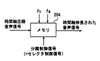
図10は時間軸伸長部104の構成を示す図である。時間軸伸長部104は主にメモリで構成され、時間軸圧縮された音声信号を分離制御信号がLOWの期間に映像のサンプリングクロックfvでもって入力し、音声のサンプリングクロック周波数faでもって出力する。これにより、もと通りに時間軸伸長された音声信号が得られる。
【0029】
図11は時間伸張部104による時間軸伸長の様子を示す図である。分離制御信号がLOWの期間のデータを音声信号とみなし、時間軸圧縮された音声信号を分離制御信号がLOWの期間だけサンプリング周波数fvで入力し、それをサンプリング周波数faでもって、たたき出すことで時間軸伸長された音声信号を得ることができる。
【0030】
次に音声クロック再生部105の動作について説明する。受信側では送信側から送られてきた映像クロックを元にしてPLL(Phase Lock Loop)をかけて音声クロックを再生し、時間軸伸長部104に音声クロックを供給する。
【0031】
このように、本発明の実施の形態1による信号伝送システムでは、送信側の多重部102において、映像信号と時間軸圧縮された音声信号とを多重制御信号に基づき多重化することにより、映像信号と音声信号を同一のデータライン106で送ることが可能になる。また、受信側では、データライン106を介して受信した映像音声多重信号を分離制御信号でもって分離することにより、映像信号と音声信号に分離することができる。
【0032】
また、多重制御信号,分離制御信号として映像信号の水平同期信号あるいは垂直同期信号を用い、また、音声信号を送信側で時間軸圧縮して受信側で時間軸伸長するようにしたので、音声信号を映像信号の隙間に多重化し、また分離することが可能となる。
【0033】
(実施の形態2)
以下、本実施の形態2にかかる信号伝送システムについて図12〜図19を用いて説明する。
図12は、実施の形態2による信号伝送システムの構成図である。
図12において、信号送信装置は、音声信号を時間軸圧縮する時間軸圧縮部201と、多重制御信号を用いて映像信号と音声信号を多重化し、映像音声多重信号として出力する多重部202と、多重制御信号を加工する多重制御信号加工部208とからなるものである。
【0034】
信号受信装置は、データライン206を介して受信した映像音声多重信号を分離する分離部203と、分離部203で分離された音声信号を時間軸伸長する時間軸伸長部204と、送信側からクロックライン207を介して受信した映像クロックから音声クロックを再生する音声クロック再生部205とからなるものである
データライン206は、信号送信装置と信号受信装置を結ぶ伝送路である。
【0035】
なお、本実施の形態2による信号伝送システムが実施の形態1の信号伝送システムと異なる点は、実施の形態2による信号伝送システムでは多重制御信号を受信側に通知しないという点である。
【0036】
以下、本実施の形態2による信号伝送システムの動作について説明する。なお、時間軸圧縮部201では実施の形態1と同様、音声信号の時間軸圧縮を行うが、時間軸圧縮のための多重制御信号が実施の形態1とは異なる。
【0037】
図13は時間軸圧縮部201の構成を示す図である。時間軸圧縮部201は実施の形態1の時間軸圧縮部101と同様メモリで構成され、音声信号のサンプリングレートを変換するものである。実施の形態1ではこのメモリの制御信号として、多重制御信号、すなわち水平同期信号または垂直同期信号をそのまま使っていたが、本実施の形態2ではこれを若干加工して用いる。具体的には多重制御信号(水平同期信号または垂直同期信号)の立ち下がりから映像のサンプリングクロックのLクロックの期間(L×1/fv sec.)カウントして立ち下がる信号を用いる。これを行う目的は、時間軸圧縮後の音声信号の手前に無信号期間(Lクロック期間)を設けて、この無信号期間を受信側で映像信号と音声信号の切り換わりタイミングと認識させるためである。
【0038】
図14は時間圧縮部201による時間軸圧縮の様子を示す図である。この図において、時間軸圧縮前の音声信号と時間軸圧縮後の音声信号との関係は、実施の形態1におけるこれらの関係とほぼ同じであるが、多重制御信号の立ち下がりに対して時間軸圧縮後の音声信号はLクロック分、遅延している。このLクロックの期間は無信号状態である。
【0039】
図15は本実施の形態2における映像信号と音声信号の多重化の様子を示す図である。図14において説明したように、映像信号と時間軸圧縮後の音声信号との間にはLクロックの無信号期間が設けられる。そして、実施の形態2では映像信号と多重化すべき時間軸圧縮された音声信号のサンプルを映像のサンプリングクロックのMクロック期間(M×1/fv sec.)として定める。このL,Mというのは整数であり、なおかつ一定の値とする。多重制御信号加工部208は、多重制御信号(水平同期信号または垂直同期信号)の立ち下がりをLクロック遅延させた新たな多重制御信号を生成するものである。このようにすることで、受信側でどこに音声信号が何サンプル点あるか認識することができ、音声信号を分離することができる。
【0040】
図16は、分離部203の構成を示す図である。図において、210は映像信号と時間軸圧縮音声信号とを分離するセレクタ回路である。211はセレクタ回路210を制御する信号を生成するセレクタ制御信号生成部である。212は無信号検出部であり、伝送路を流れてくる映像音声多重信号の無信号状態を検出するものである。カウンタ213は音声信号のサンプルが存在する期間をカウントするもので、Mクロック期間(M×1/fv sec.)をカウントするものである。
【0041】
次に分離部203の具体的な動作を説明する。無信号検出部212はLクロック期間(L×1/fv sec.)の無信号状態を検出したとき、その出力のレベルをHIGHからLOWに変化させる。カウンタ213のカウント開始(出力の立ち下り)のタイミングは無信号検出部212の出力の立ち下りタイミングと同じである。カウンタ213は無信号検出部212の出力の立ち下がりからMクロック期間カウントしたら、その出力をLOWからHIGHに立ち上げる。セレクタ制御信号生成部211は無信号検出部212の出力とカウンタ213の出力とのOR(論理和)をとる回路である。セレクタ回路210は、セレクタ制御信号生成部211の出力がHIGHの期間にはAを選択して映像信号を抽出し、セレクタ制御信号生成部211の出力がLOWの期間にはBを選択して時間軸圧縮された音声信号を抽出する。
【0042】
図17は、本実施の形態2における映像信号と音声信号との分離の様子を示す。伝送路上の映像音声多重信号には、無信号期間がLクロック期間続いた後、音声信号サンプルがMクロック期間存在する。そして、図16で説明したように、セレクタ制御信号がLOWの期間は、セレクタをBに切り換えておき、それ以外の期間はAにセットしておけば、映像音声多重信号から映像信号と音声信号とを分離して抽出することができる。
【0043】
図18は時間軸伸長部204の構成を示す図である。時間軸伸長部204は実施の形態1の時間軸伸長部104と同様にメモリで構成されるが、分離制御信号としては図16で説明したセレクタ制御信号が用いられる。
【0044】
図19は、時間軸伸張部204による時間軸伸長の様子を示す図である。時間軸圧縮された音声信号を、分離制御信号すなわちセレクタ制御信号がLOWの期間だけサンプリング周波数fvで時間軸伸長部204に入力し、それをオーディオのサンプリングクロックfaでたたき出すことにより時間軸伸長された音声信号を得ることができる。
【0045】
このように、本実施の形態2による信号伝送システムでは、多重制御信号を受信側に伝えることなく、上記実施の形態1による信号伝送システムと同様の作用を実現できる。すなわち、実施の形態2では、映像信号と音声信号とが多重化される期間において、映像信号と音声信号の間にLクロック期間の信号状態を設け、また、音声信号のサンプル点をMクロック期間として一定とし、受信側で、無信号期間をLクロック期間検出後、Mクロック期間を音声信号の分離タイミングとみなす構成とすることにより、多重制御信号を受信側に伝えることなく音声信号と映像信号の分離を可能とできる。
【0046】
(実施の形態3)
以下、本実施の形態3にかかる信号伝送システムについて図20〜図23を用いて説明する。なお、実施の形態3は、実施の形態1,2による信号伝送システムをDVI(Digital Visual Interface)規格に適用したものである。
【0047】
図20は、実施の形態3による信号伝送システムの構成を示す図である。
図20において、301は時間軸圧縮部で、これは実施の形態1あるいは2で用いたものと同一である。302は分解部であり、時間軸圧縮された音声信号をDVI規格のCTL2,CTL3,CTL1の信号に分解して重畳するものである。303〜305はTMDSエンコーダ/シリアライザ、306〜308はTMDSデコーダ/リカバリーであり、これらは従来例の技術で説明したものと同じである。309は合成部であり、CTL1,2,3からきた音声信号を合成するものである。310は時間軸伸長部であり、合成部309から出力された時間軸圧縮されたままの音声信号を伸長するものである。この図において、伝送路のチャンネル0にはBLUEと映像信号のHSYNC,VSYNC(水平同期信号,垂直同期信号)が時分割多重されたシリアルデータが伝送され、チャンネル1においてはGREENと音声(CTL1)が時分割多重されたシリアルデータが伝送され、チャンネル2ではREDと音声(CTL2,3)が時分割多重されたシリアルデータが伝送される。
【0048】
以上のように構成された信号伝送システムの動作について説明する。
図21に実施の形態3における伝送路上の信号の様子を示す。
まず、1番上にTMDSエンコーダへの入力のデータを示す。DE(データイネーブル)信号がLOWの間にCTL(コントロール信号)が挿入され、このCTL1,2,3のところに時間軸圧縮された音声信号をのせてTMDSエンコードされる。そして、伝送路上の信号ではチャンネル2にエンコードされたCTL2,3が重畳され、チャンネル1にエンコードされたCTL1が重畳される。そして、これらにより伝送路では、水平同期信号,または垂直同期信号の期間にオーディオ(音声信号)が重畳されていることになる。そして1番下に受信側でTMDSデコード,リカバーされたデータを示す。このリカバーされたデータというのは、送信側における入力のデータと全く同一のものである。
【0049】
次に受信側での音声を分離する方法を説明する。
図22に示すように、まずチャンネル0のデータの一定期間をデータ一定期間検出回路350により検出する。このデータの一定期間というのは、水平同期期間あるいは垂直同期期間である。このデータの一定期間を検出して、DE(データイネーブル)信号を生成してやり、このDE信号がLOWの期間を音声信号が多重化されている期間とみなし、チャンネル1,チャンネル2のデコード・映像音声分離回路351,352に対してDE信号を供給しチャンネル1,チャンネル2のデコーダで映像信号と音声信号を分離する。そして、CTL1,CTL2,CTL3のラインの分離された音声信号があらわれる。
【0050】
次に受信側でのデコードの方法について説明する。
図23において、チャンネル2に伝送されてきた映像音声多重信号をシリアル/パラレル変換回路360でシリアル/パラレル変換し、DE(データイネーブル)信号がHIGHの期間は映像信号とみなし、デコーダ362により10ビット/8ビットTMDSデコードを行い、これによりRED信号を得ることができる。そして、DE(データイネーブル)信号がLOWの期間は音声信号とみなし、デコーダ363により10ビット/2ビットTMDSデコードを行い、CTL2,CTL3のラインに音声信号を得ることができる。同様にチャンネル1においても伝送されてきた映像音声多重信号をシリアル/パラレル変換回路361でシリアル/パラレル変換し、DE(データイネーブル)信号がHIGHの期間はGREENの映像信号とみなし、デコーダ364により10ビット/8ビットTMDSデコードを行う。そしてDE(データイネーブル)信号がLOWの期間にはデコーダ365により10ビット/2ビットTMDSデコードを行い、CTL1に音声信号を得ることができる。
【0051】
このようにして、CTL(コントロール)ライン上で得られた音声信号を、合成部309で合成し、さらに時間軸伸長部310でレート変換することにより、元の音声信号を得ることができる。
【0052】
次に分解部302,合成部309の動作について説明する。
分解部302においては、時間軸圧縮された音声信号をCTL2,3,1の3本に分解するわけであるが、音声信号の帯域によってはCTL2の1本のみを、あるいはCTL2,3の2本を使うという使い方をしても構わない。また、音声信号のサンプリング点の順番に従って、CTL2,3,1,2,3,1の順に分解すればよい。合成部309では、伝送路から流れてきた音声信号をデコードしたものに対して、CTL2,3,1の順番で音声信号がやってきているとみなして、合成すればよい。なお、CTL2,3,1の順でなくともこの3本を任意の順番で使っても構わないが、送信側と受信側でこの分解,合成の順は取り決めておく必要がある。
【0053】
このように、実施の形態3による信号伝送システムでは、実施の形態1,2における信号伝送システムの構成をDVI規格に適用し、音声信号を時間軸圧縮したものをCTL2,3,1のラインに分解し、受信側ではCTL2,3,1で伝送されてきた音声信号を合成し、時間軸伸長して音声信号を復元するようにしたから、従来映像しか伝送できなかったDVI規格の信号伝送システムにおいて、音声信号の伝送も可能とできる。
【0054】
(実施の形態4)
以下、本実施の形態4にかかる信号伝送システムについて図24及び図25を用いて説明する。なお、実施の形態4は実施の形態1〜3とは異なり、音声信号を映像信号の隙間を用いて伝送するものではなく、DVI規格の信号伝送システムにおいて用いられる3本の伝送路のうちの1本を音声信号用の伝送路として確保するようにしたものである。すなわち、DVI規格では映像信号の伝送は、RED,GREEN,BLUEといったコンポーネント信号で行われているが、本実施の形態4ではY,Pb,PrといったY色差信号で伝送するモードを追加し、またそこで空いたチャンネルを音声信号に割り当てるようにしたものである。
【0055】
図24は、実施の形態4による信号伝送システムの構成を示す図である。
図において、401はセレクタであり、RED信号と輝度信号(Y)を選択してTMDSエンコーダに供給するものである。402もセレクタであり、GREEN信号とPbまたはPr信号を選択するものである。403はセレクタであり、BLUE信号と音声信号からどちらか一方を選択するものである。404〜406はTMDSエンコーダ/シリアライザ、407〜409はTMDSデコーダ/リカバリーである。これらの構成は実施の形態1,2,3と同一である。
【0056】
この実施の形態4の特徴としては、映像信号の伝送にY色差伝送を用いることである。Y色差伝送では、例えば4:2:0伝送というものがある。4:2:0伝送というのは図25に示すように、色信号のレートを輝度信号のレートの半分にするものである。具体的には輝度信号に対して色信号のサンプリング数を半分にする。これにより、DVIの伝送路では2チャンネルでもって映像信号を伝送することが可能となる。具体的にはチャンネル2で輝度信号、チャンネル1で色信号Pb,Pr信号を伝送する。そして空いたチャンネル0に音声信号を重畳するものである。この音声信号は時間軸圧縮されていない元のままの音声信号である。
【0057】
このように本実施の形態4による信号伝送システムでは、Y,Pb,PrといったY色差信号で伝送するモードを追加し、またそこで空いたチャンネルを音声信号に割り当てるようにしたから、映像信号とともに音声信号を伝送できるDVI規格に適合する信号伝送システムを実現できる。
【0058】
なお、実施の形態4では、Y,Pb/Pr,音声をそれぞれチャンネル2,チャンネル1,チャンネル0に割当てたが、この割当ての順序はこれに限るものではない。
【0059】
なお、本発明の実施の形態において、信号の多重化と送信を多重部が行っているが、多重と送信を別々の構成要件としても構わない。
【0060】
【発明の効果】
本発明の信号送信装置によれば、伝送路を介して信号受信装置に接続された信号送信装置において、第1の信号を時間軸圧縮する時間軸圧縮手段と、第2の信号に基づいて多重制御信号を生成する多重制御信号発生装置と、上記多重制御信号発生装置により生成した多重制御信号を用いて、上記時間軸圧縮された第1の信号と、上記第2の信号と、第3の信号とを多重化し多重信号として出力する信号多重手段と、上記多重信号及び上記多重制御信号を上記信号受信装置に送信する信号送信手段とを、備えたことより、第1、第2、第3の信号を同一の伝送路で伝送する信号伝送システムを実現可能である。
【0061】
本発明の信号送信装置によれば、伝送路を介して信号受信装置に接続された信号送信装置において、第1の信号を時間軸圧縮する時間軸圧縮手段と、第2の信号に基づいて多重制御信号を生成する多重制御信号発生装置と、上記多重制御信号発生装置により生成した多重制御信号を用いて、上記時間軸圧縮された第1の信号と、上記第2の信号と、第3の信号とを多重化し多重信号として出力する信号多重手段と、上記多重信号を上記信号受信装置に送信する信号送信手段と、を備えたことより、多重制御信号を信号受信装置に伝送することなく、第1,第2,第3の信号を同一の伝送路で伝送する信号伝送システムを実現可能である。
【0062】
本発明の信号送信装置によれば、上記信号送信装置において、上記第1の信号は音声信号であり、上記第2の信号は水平同期信号または垂直同期信号であり、上記第3の信号は映像信号であるようにしたので、映像信号とともに音声信号を伝送できるDVI規格の信号伝送システムを実現可能である。
【0063】
本発明の信号送信装置によれば、RGBの映像信号をシリアルデータとして伝送するDVI伝送規格の信号送信装置において、上記RGBの映像信号をシリアルデータとして伝送する第1のモードに加え、輝度信号、色差信号、及び音声信号の3つの信号を伝送する第2のモードを有し、上記第1のモードと上記第2のモードを切り替える切り替え手段を備えたことより、映像信号とともに音声信号を伝送できるDVI規格の信号伝送システムを実現可能である。
【0064】
本発明の信号受信装置によれば、伝送路を介して信号送信装置に接続された信号受信装置において、上記信号送信装置から、時間軸多重された第1の信号、第2の信号、及び第3の信号が多重化された多重信号を受信する第1の受信手段と、上記信号送信装置から多重制御信号を受信する第2の受信手段と、上記第2の受信手段にて受信した上記多重制御信号を用いて、上記第1の受信手段にて受信した上記多重信号を上記第1,第2の信号に分離する分離手段と、上記分離手段により分離された第1の信号を時間軸伸張する時間軸伸張手段と、を備えたことより、第1,第2,第3の信号を同一の伝送路で伝送できる信号伝送システムを実現可能である。
【0065】
本発明の信号受信装置によれば、伝送路を介して信号送信装置に接続された信号受信装置において、上記信号送信装置から、時間軸多重された第1の信号、第2の信号、及び第3の信号が多重化された多重信号を受信する受信手段と、上記多重信号から上記第2の信号を検出する検出手段と、上記検出手段により検出された第2の信号に基づいて多重制御信号を生成する多重制御信号発生手段と、上記多重制御信号を用いて、上記多重信号を上記第1、第2、第3の信号に分離する分離手段と、上記分離手段により分離された上記第1の信号を時間軸伸張する時間軸伸張手段と、を備えたことより、信号送信装置から多重制御信号を受信することなく、多重信号を分離でき、また、第1,第2,第3の信号を同一の伝送路で受信できる信号伝送システムを実現可能である。
【0066】
本発明の信号受信装置によれば、上記信号受信装置において、上記第1の信号は音声信号であり、上記第2の信号は水平同期信号または垂直同期信号であり、上記第3の信号は映像信号であるようにしたので、映像信号とともに音声信号を伝送できるDVI規格の信号伝送システムを実現可能である。
【0067】
本発明の信号受信装置によれば、RGBの映像信号をシリアルデータとして受信するDVI伝送規格の信号受信装置において、上記RGBの映像信号をシリアルデータとして受信する第1のモードに加え、輝度信号、色差信号、及び音声信号の3つの信号を受信する第2のモードを有し、上記第1のモードと上記第2のモードを切り替える切り替え手段を備えたことより、映像信号とともに音声信号を伝送できるDVI規格の信号伝送システムを実現可能である。
【図面の簡単な説明】
【図1】図1は、本発明の実施の形態1による信号伝送システムの構成を示す図である。
【図2】映像信号と時間軸圧縮前の音声信号との関係を示す図である。
【図3】水平同期期間及び垂直同期期間を説明するための図である。
【図4】実施の形態1による信号伝送システムの時間軸圧縮部の構成を示す図である。
【図5】実施の形態1による信号伝送システムにおける時間軸圧縮を説明するための図である。
【図6】実施の形態1による信号伝送システムの多重部の構成を示す図である。
【図7】実施の形態1による信号伝送システムにおける映像信号と音声信号の多重の様子を示す図である。
【図8】実施の形態1による信号伝送システムの分離部の構成を示す図である。
【図9】実施の形態1による信号伝送システムにおける映像信号と音声信号の分離の様子を示す図である。
【図10】実施の形態1による信号伝送システムの時間軸伸長部の構成を示す図である。
【図11】実施の形態1による信号伝送システムにおける時間軸伸長を説明するための図である。
【図12】実施の形態2による信号伝送システムの構成を示す図である。
【図13】実施の形態2による信号伝送システムの時間軸圧縮部の構成を示す図である。
【図14】実施の形態2による信号伝送システムにおける時間軸圧縮を説明するための図である。
【図15】実施の形態2による信号伝送システムにおける映像信号と音声信号の多重の様子を示す図である。
【図16】実施の形態2による信号伝送システムの分離部の構成を示す図である。
【図17】実施の形態2による信号伝送システムにおける映像信号と音声信号の分離の様子を示す図である。
【図18】実施の形態2による信号伝送システムの時間軸伸長部の構成を示す図である。
【図19】実施の形態2による信号伝送システムにおける時間軸伸長を説明するための図である。
【図20】実施の形態3による信号伝送システムの構成を示す図である。
【図21】実施の形態3による信号伝送システムにおけるデータの様子を示す図である。
【図22】実施の形態3による信号伝送システムにおける受信側での音声分離の方法を示す図である。
【図23】実施の形態3による信号伝送システムにおける受信側でのデコードの方法を示す図である。
【図24】実施の形態4による信号伝送システムの構成を示す図である。
【図25】実施の形態4による信号伝送システムにおける伝送路上の信号イメージを示す図である。
【図26】従来の信号伝送システムの構成を示す図である。
【符号の説明】
101,201 時間軸圧縮部
102,202 多重部
103,203 分離部
104,204 時間軸伸長部
105,205 音声クロック再生部
106,206 データライン
107,207 クロックライン
208 多重制御信号加工部
210 セレクタ回路
211 セレクタ制御信号生成部
212 無信号検出部
213 カウンタ
301 時間軸圧縮部
302 分解部
303〜305 TMDSエンコーダ/シリアライザ
306〜308 TMDSデコーダ/リカバリー
309 合成部
310 時間軸伸長部
401〜403 セレクタ
404〜406 TMDSエンコーダ/シリアライザ
407〜409 TMDSデコーダ/リカバリー[0001]
BACKGROUND OF THE INVENTION
The present invention,The present invention relates to a signal receiving device.
[0002]
[Prior art]
A conventional DVI (Digital Visual Interface) standard signal transmission system will be described with reference to FIG. FIG. 26 is a diagram illustrating a configuration of a conventional transmission system.
In the figure,
[0003]
The DE (data enable) signal is a signal indicating a period in which component signals such as RED, GREEN, and BLUE exist, and is a HIGH active signal. For example, the period during which the DE signal is LOW is a horizontal synchronizing signal period or a vertical synchronizing signal period of video.
[0004]
CTL (control) signals CTL0, CTL1, CTL2, and CTL3 are prepared as control signals. However, in the current DVI standard, these signals are unused. Specifically, the signal level is always 0.
[0005]
A conventional signal transmission system configured as described above will be described.
The TMDS encoders /
[0006]
The TMDS decoders /
[0007]
[Problems to be solved by the invention]
However, the DVI standard is a standard for transmitting only a video signal, and there is a problem that a conventional signal transmission system cannot transmit an audio signal.
[0008]
The present invention has been made to solve the above problems, and can realize a DVI standard signal transmission system capable of transmitting an audio signal together with a video signal.FaithAn object of the present invention is to provide a signal receiving apparatus.
[0009]
[Means for Solving the Problems]
In the vertical blanking period of a digital video signal, the present invention includes a multiplexed signal that is a signal in which a digital audio signal compressed in time axis is multiplexed, and a region including the digital video signal or the digital audio signal in the multiplexed signal A receiving unit that receives the control signal, and a separating unit that separates the digital audio signal from the multiplexed signal using the control signal received by the receiving unit. It is a signal receiving device.
[0017]
DETAILED DESCRIPTION OF THE INVENTION
Hereinafter, embodiments of the present invention will be described with reference to the drawings. In addition, embodiment shown here is an example to the last, Comprising: It is not necessarily limited to this embodiment.
[0018]
(Embodiment 1)
The signal transmission system according to the first embodiment will be described below with reference to FIGS.
FIG. 1 is a diagram showing a configuration of a signal transmission system according to the first embodiment.
In FIG. 1, a signal transmission apparatus multiplexes a video signal and a time-axis-compressed audio signal using a time-
[0019]
The signal receiving apparatus uses a multiplex control signal to separate a video / audio multiplexed signal in which a video signal and an audio signal received via the
[0020]
The
Note that the multiplex control signal is a signal that multiplexes the audio signal in the idle time of the video signal such as the horizontal sync signal or the vertical sync signal of the video signal, for example. Not).
[0021]
Next, the operation of the signal transmission system according to the first embodiment will be described.
First, FIG. 2 schematically shows the relationship between a video signal and an audio signal before time axis compression. In general, since a video signal has a larger amount of data than an audio signal, one sample of the audio signal corresponds approximately in time to the number of video signal samples. In the signal transmission system according to the first embodiment, this video / audio signal is temporally compressed and multiplexed into an area where no video signal exists. Specifically, the time when the video signal does not exist includes, for example, a horizontal synchronization period and a vertical synchronization period of the video signal as shown in FIG. In FIG. 3, hatched portions other than the effective screen correspond to the synchronization period. In FIG. 3, an SD screen of MP @ ML (main profile main level) of MPEG2 is taken as an example. The entire screen has 858 pixels horizontally and 525 lines vertically. The effective screen among them is 720 pixels wide and 480 lines long, and the difference between the entire screen and this effective screen is the synchronization period. Audio signals are multiplexed during this synchronization period.
[0022]
Next, the operation on the transmission side will be described.
FIG. 4 is a diagram showing the configuration of the time
[0023]
FIG. 5 is a diagram illustrating a state of time axis compression by the time
[0024]
FIG. 6 is a diagram illustrating a configuration of the
[0025]
FIG. 7 shows how video and audio signals are multiplexed by the
In the figure, the video signal and the audio signal after time axis compression are the upper two stages. White circles are sampling points for video signals, and black circles are sampling points for audio signals. The state where the audio signal is multiplexed with the video signal during the period when the multiplexing control signal is LOW is shown at the bottom. Then, this video / audio multiplexed signal becomes a signal on the transmission line and is sent out to the transmission line.
[0026]
Next, the operation on the receiving side will be described.
FIG. 8 is a diagram illustrating a configuration of the
[0027]
FIG. 9 is a diagram showing how the video signal and the audio signal are separated by the
The video / audio multiplexed signal flowing from the
[0028]
FIG. 10 is a diagram illustrating a configuration of the time
[0029]
FIG. 11 is a diagram illustrating how the
[0030]
Next, the operation of the audio
[0031]
As described above, in the signal transmission system according to the first embodiment of the present invention, the video signal and the time-axis compressed audio signal are multiplexed based on the multiplex control signal in the transmission-
[0032]
In addition, the horizontal sync signal or vertical sync signal of the video signal is used as the multiplex control signal and the separation control signal, and the audio signal is time-axis compressed on the transmission side and extended on the reception side. Can be multiplexed and separated in the gap of the video signal.
[0033]
(Embodiment 2)
Hereinafter, the signal transmission system according to the second exemplary embodiment will be described with reference to FIGS.
FIG. 12 is a configuration diagram of a signal transmission system according to the second embodiment.
In FIG. 12, a signal transmission apparatus includes a time
[0034]
The signal receiving apparatus includes a
The
[0035]
The signal transmission system according to the second embodiment is different from the signal transmission system according to the first embodiment in that the signal transmission system according to the second embodiment does not notify the receiving side of the multiplex control signal.
[0036]
Hereinafter, the operation of the signal transmission system according to the second embodiment will be described. The time
[0037]
FIG. 13 is a diagram illustrating a configuration of the time
[0038]
FIG. 14 is a diagram illustrating a state of time axis compression by the
[0039]
FIG. 15 is a diagram showing how video and audio signals are multiplexed in the second embodiment. As described with reference to FIG. 14, an L clock no-signal period is provided between the video signal and the audio signal after time axis compression. In the second embodiment, a sample of a time-base compressed audio signal to be multiplexed with a video signal is defined as an M clock period (M × 1 / fv sec.) Of a video sampling clock. L and M are integers and are constant values. The multiplex control
[0040]
FIG. 16 is a diagram illustrating a configuration of the
[0041]
Next, a specific operation of the
[0042]
FIG. 17 shows how the video signal and the audio signal are separated in the second embodiment. In the audio / video multiplexed signal on the transmission line, after a non-signal period lasts L clock periods, audio signal samples exist for M clock periods. As described with reference to FIG. 16, if the selector is switched to B when the selector control signal is LOW and set to A during the other periods, the video signal and audio signal are converted from the video / audio multiplexed signal. And can be extracted separately.
[0043]
FIG. 18 is a diagram illustrating a configuration of the time
[0044]
FIG. 19 is a diagram illustrating a state of time axis extension by the time
[0045]
Thus, in the signal transmission system according to the second embodiment, the same operation as that of the signal transmission system according to the first embodiment can be realized without transmitting the multiplex control signal to the receiving side. That is, in the second embodiment, in the period in which the video signal and the audio signal are multiplexed, the signal state of the L clock period is provided between the video signal and the audio signal, and the sample point of the audio signal is set to the M clock period. And the reception side detects the non-signal period as the L clock period and then regards the M clock period as the separation timing of the audio signal, so that the audio signal and the video signal can be transmitted without transmitting the multiplexed control signal to the reception side. Can be separated.
[0046]
(Embodiment 3)
Hereinafter, the signal transmission system according to the third embodiment will be described with reference to FIGS. In the third embodiment, the signal transmission system according to the first and second embodiments is applied to the DVI (Digital Visual Interface) standard.
[0047]
FIG. 20 is a diagram illustrating a configuration of a signal transmission system according to the third embodiment.
In FIG. 20,
[0048]
The operation of the signal transmission system configured as described above will be described.
FIG. 21 shows a signal state on the transmission line in the third embodiment.
First, data input to the TMDS encoder is shown at the top. A CTL (control signal) is inserted while the DE (data enable) signal is LOW, and a time-base-compressed audio signal is placed at these
[0049]
Next, a method for separating audio on the receiving side will be described.
As shown in FIG. 22, first, a certain period of data of
[0050]
Next, a decoding method on the receiving side will be described.
In FIG. 23, the video / audio multiplexed signal transmitted to the
[0051]
In this way, the voice signal obtained on the CTL (control) line is synthesized by the
[0052]
Next, operations of the disassembling
In the decomposing
[0053]
As described above, in the signal transmission system according to the third embodiment, the configuration of the signal transmission system according to the first and second embodiments is applied to the DVI standard, and the time-base compressed audio signal is applied to the
[0054]
(Embodiment 4)
The signal transmission system according to the fourth embodiment will be described below with reference to FIGS. 24 and 25. The fourth embodiment is different from the first to third embodiments in that the audio signal is not transmitted using the gap between the video signals, but the three transmission paths used in the DVI standard signal transmission system are not used. One is secured as a transmission path for audio signals. That is, in the DVI standard, transmission of video signals is performed by component signals such as RED, GREEN, and BLUE, but in the fourth embodiment, a mode for transmitting by Y color difference signals such as Y, Pb, and Pr is added. Therefore, an empty channel is assigned to the audio signal.
[0055]
FIG. 24 is a diagram illustrating a configuration of a signal transmission system according to the fourth embodiment.
In the figure, 401 is a selector which selects a RED signal and a luminance signal (Y) and supplies them to the TMDS encoder.
[0056]
A feature of the fourth embodiment is that Y color difference transmission is used for transmission of a video signal. In Y color difference transmission, there is, for example, 4: 2: 0 transmission. As shown in FIG. 25, the 4: 2: 0 transmission means that the color signal rate is halved of the luminance signal rate. Specifically, the sampling number of the color signal is halved with respect to the luminance signal. As a result, the video signal can be transmitted with two channels on the DVI transmission line. Specifically, the luminance signal is transmitted on
[0057]
As described above, in the signal transmission system according to the fourth embodiment, a mode in which Y color difference signals such as Y, Pb, and Pr are transmitted is added, and an empty channel is assigned to the audio signal. A signal transmission system conforming to the DVI standard capable of transmitting signals can be realized.
[0058]
In the fourth embodiment, Y, Pb / Pr, and audio are assigned to
[0059]
In the embodiment of the present invention, multiplexing and transmission of signals are performed by the multiplexing unit. However, multiplexing and transmission may be configured separately.
[0060]
【The invention's effect】
The present inventionThe faithAccording to the signal transmission device, in the signal transmission device connected to the signal reception device via the transmission line, the time axis compression means for time axis compression of the first signal, and the multiplex control signal based on the second signal are transmitted. A multiplex control signal generator to be generated, and a first signal that is time-axis-compressed using the multiplex control signal generated by the multiplex control signal generator, the second signal, and a third signal. Since it comprises signal multiplexing means for multiplexing and outputting as a multiplexed signal, and signal transmission means for transmitting the multiplexed signal and the multiplexed control signal to the signal receiving device, the first, second and third signals are provided. It is possible to realize a signal transmission system that transmits on the same transmission path.
[0061]
The present inventionThe faithAccording to the signal transmission device, in the signal transmission device connected to the signal reception device via the transmission line, the time axis compression means for time axis compression of the first signal, and the multiplex control signal based on the second signal are transmitted. A multiplex control signal generator to be generated, and a first signal that is time-axis-compressed using the multiplex control signal generated by the multiplex control signal generator, the second signal, and a third signal. By providing a signal multiplexing means for multiplexing and outputting as a multiplexed signal, and a signal transmitting means for transmitting the multiplexed signal to the signal receiving device, the first control signal is transmitted without transmitting the multiplexed control signal to the signal receiving device. It is possible to realize a signal transmission system that transmits the second and third signals through the same transmission path.
[0062]
The present inventionThe faithAccording to the No. transmitterthe aboveIn the signal transmission device, the first signal is an audio signal, the second signal is a horizontal synchronization signal or a vertical synchronization signal, and the third signal is a video signal. It is possible to realize a DVI standard signal transmission system capable of transmitting an audio signal.
[0063]
The present inventionThe faithIn the signal transmission device of the DVI transmission standard for transmitting RGB video signals as serial data, in addition to the first mode for transmitting RGB video signals as serial data, a luminance signal, a color difference signal, And a second mode for transmitting three signals of the audio signal, and provided with a switching means for switching between the first mode and the second mode, so that the audio signal can be transmitted together with the video signal. A signal transmission system can be realized.
[0064]
The present inventionThe faithAccording to the signal receiving device, in the signal receiving device connected to the signal transmitting device via the transmission path, the first signal, the second signal, and the third signal time-multiplexed from the signal transmitting device. A first receiving means for receiving a multiplexed signal obtained by multiplexing, a second receiving means for receiving a multiplexed control signal from the signal transmitting apparatus, and the multiplexed control signal received by the second receiving means. A separating means for separating the multiplexed signal received by the first receiving means into the first and second signals, and a time axis for extending the time axis of the first signal separated by the separating means; By providing the expansion means, it is possible to realize a signal transmission system capable of transmitting the first, second, and third signals through the same transmission path.
[0065]
The present inventionThe faithAccording to the signal receiving device, in the signal receiving device connected to the signal transmitting device via the transmission path, the first signal, the second signal, and the third signal time-multiplexed from the signal transmitting device. Receiving means for receiving the multiplexed signal multiplexed, detecting means for detecting the second signal from the multiplexed signal, and generating a multiplex control signal based on the second signal detected by the detecting means Multiplex control signal generating means, separation means for separating the multiplexed signal into the first, second and third signals using the multiple control signal, and the first signal separated by the separation means And a time axis extending means for extending the time axis, so that the multiplexed signal can be separated without receiving the multiplexed control signal from the signal transmission device, and the first, second and third signals can be identical. Signal transmission system that can be received on the transmission line It is possible to realize.
[0066]
The present inventionThe faithAccording to the number receiverthe aboveIn the signal receiving apparatus, the first signal is an audio signal, the second signal is a horizontal synchronization signal or a vertical synchronization signal, and the third signal is a video signal. It is possible to realize a DVI standard signal transmission system capable of transmitting an audio signal.
[0067]
The present inventionThe faithIn the signal receiving device of the DVI transmission standard that receives the RGB video signal as serial data, in addition to the first mode for receiving the RGB video signal as serial data, the luminance signal, the color difference signal, And a second mode for receiving three signals of the audio signal, and switching means for switching between the first mode and the second mode, so that the audio signal can be transmitted together with the video signal. A signal transmission system can be realized.
[Brief description of the drawings]
FIG. 1 is a diagram showing a configuration of a signal transmission system according to a first embodiment of the present invention.
FIG. 2 is a diagram illustrating a relationship between a video signal and an audio signal before time axis compression;
FIG. 3 is a diagram for explaining a horizontal synchronization period and a vertical synchronization period.
4 is a diagram showing a configuration of a time axis compression unit of the signal transmission system according to
FIG. 5 is a diagram for explaining time axis compression in the signal transmission system according to the first embodiment;
6 is a diagram showing a configuration of a multiplexing unit of the signal transmission system according to
7 is a diagram showing a state of multiplexing video signals and audio signals in the signal transmission system according to
8 is a diagram showing a configuration of a separation unit of the signal transmission system according to
FIG. 9 is a diagram illustrating a state of separation of a video signal and an audio signal in the signal transmission system according to the first embodiment.
FIG. 10 is a diagram illustrating a configuration of a time axis extension unit of the signal transmission system according to the first embodiment.
FIG. 11 is a diagram for explaining time axis expansion in the signal transmission system according to the first embodiment;
FIG. 12 is a diagram illustrating a configuration of a signal transmission system according to a second embodiment.
FIG. 13 is a diagram showing a configuration of a time axis compression unit of a signal transmission system according to a second embodiment.
FIG. 14 is a diagram for explaining time axis compression in the signal transmission system according to the second embodiment;
FIG. 15 is a diagram illustrating how video and audio signals are multiplexed in the signal transmission system according to the second embodiment.
FIG. 16 is a diagram showing a configuration of a separation unit of the signal transmission system according to the second embodiment.
FIG. 17 is a diagram illustrating a state of separation of a video signal and an audio signal in the signal transmission system according to the second embodiment.
FIG. 18 is a diagram illustrating a configuration of a time axis extension unit of the signal transmission system according to the second embodiment.
FIG. 19 is a diagram for explaining time axis expansion in the signal transmission system according to the second embodiment;
FIG. 20 is a diagram illustrating a configuration of a signal transmission system according to a third embodiment.
FIG. 21 is a diagram showing a state of data in the signal transmission system according to the third embodiment.
FIG. 22 is a diagram showing a method of voice separation on the receiving side in the signal transmission system according to the third embodiment.
FIG. 23 is a diagram illustrating a decoding method on the reception side in the signal transmission system according to the third embodiment.
FIG. 24 is a diagram illustrating a configuration of a signal transmission system according to a fourth embodiment.
FIG. 25 is a diagram showing a signal image on a transmission line in the signal transmission system according to the fourth embodiment.
FIG. 26 is a diagram illustrating a configuration of a conventional signal transmission system.
[Explanation of symbols]
101,201 Time axis compression unit
102,202 Multiplexer
103, 203 Separation unit
104,204 Time base extension
105, 205 Audio clock reproduction unit
106,206 Data line
107, 207 clock line
208 Multiple control signal processing unit
210 Selector circuit
211 Selector control signal generator
212 No signal detector
213 counter
301 Time base compression unit
302 Disassembly part
303-305 TMDS encoder / serializer
306-308 TMDS decoder / recovery
309 synthesis unit
310 Time base extension
401-403 selector
404-406 TMDS encoder / serializer
407-409 TMDS decoder / recovery
Claims (3)
デジタルビデオ信号の垂直ブランキング期間に、時間軸圧縮されたデジタル音声信号が多重化された信号である多重信号であり、第1のチャンネル、第2のチャンネル、第3のチャンネルを用いて伝送し、前記音声信号は前記第2のチャンネルと前記第3のチャンネルに多重化されて伝送された多重信号と、
前記第1のチャンネルに含まれた、前記多重信号中における前記デジタルビデオ信号または前記デジタル音声信号を含む領域を示す制御信号と、
を受信する受信部と、
前記受信部にて受信した前記制御信号を用いて、前記多重信号から前記デジタル音声信号を分離する分離部と、
を備えたことを特徴とする信号受信装置。In the signal receiving device connected to the signal transmitting device via the transmission path,
A multiplexed signal that is a multiplexed signal of a digital audio signal that has been time-axis compressed during the vertical blanking period of the digital video signal, and is transmitted using the first channel, the second channel, and the third channel. The audio signal is multiplexed and transmitted on the second channel and the third channel, and
A control signal indicating a region including the digital video signal or the digital audio signal in the multiplexed signal included in the first channel;
A receiving unit for receiving
A separation unit that separates the digital audio signal from the multiplexed signal using the control signal received by the reception unit;
A signal receiving apparatus comprising:
デジタルビデオ信号の垂直ブランキング期間および水平ブランキング期間に、時間軸圧縮されたデジタル音声信号が多重化された信号である、
請求項1記載の信号受信装置。The multiplexed signal is:
In the vertical blanking period and the horizontal blanking period of the digital video signal, it is a signal in which a digital audio signal compressed in time axis is multiplexed.
The signal receiving apparatus according to claim 1.
前記多重信号に、デジタル音声信号が重畳されている場合と、前記多重信号にデジタル音声信号が多重されていない場合とで異なる値を表すことで、前記デジタルビデオ信号または前記デジタル音声信号を含む領域を示す、
請求項1に記載の信号受信装置。The control signal is
An area including the digital video signal or the digital audio signal by representing different values depending on whether the digital audio signal is superimposed on the multiplexed signal and the digital audio signal is not multiplexed on the multiplexed signal. Showing,
The signal receiving device according to claim 1.
Priority Applications (1)
| Application Number | Priority Date | Filing Date | Title |
|---|---|---|---|
| JP2001221841A JP5023421B2 (en) | 2000-07-21 | 2001-07-23 | Signal receiving device |
Applications Claiming Priority (4)
| Application Number | Priority Date | Filing Date | Title |
|---|---|---|---|
| JP2000-220749 | 2000-07-21 | ||
| JP2000220749 | 2000-07-21 | ||
| JP2000220749 | 2000-07-21 | ||
| JP2001221841A JP5023421B2 (en) | 2000-07-21 | 2001-07-23 | Signal receiving device |
Related Child Applications (1)
| Application Number | Title | Priority Date | Filing Date |
|---|---|---|---|
| JP2010288355A Division JP5370350B2 (en) | 2000-07-21 | 2010-12-24 | Signal receiving device |
Publications (3)
| Publication Number | Publication Date |
|---|---|
| JP2002125207A JP2002125207A (en) | 2002-04-26 |
| JP2002125207A5 JP2002125207A5 (en) | 2011-02-17 |
| JP5023421B2 true JP5023421B2 (en) | 2012-09-12 |
Family
ID=26596428
Family Applications (1)
| Application Number | Title | Priority Date | Filing Date |
|---|---|---|---|
| JP2001221841A Expired - Fee Related JP5023421B2 (en) | 2000-07-21 | 2001-07-23 | Signal receiving device |
Country Status (1)
| Country | Link |
|---|---|
| JP (1) | JP5023421B2 (en) |
Families Citing this family (9)
| Publication number | Priority date | Publication date | Assignee | Title |
|---|---|---|---|---|
| JP2004023187A (en) * | 2002-06-12 | 2004-01-22 | Matsushita Electric Ind Co Ltd | Data transmission apparatus and data receiving apparatus |
| JP5469582B2 (en) * | 2010-10-25 | 2014-04-16 | パナソニック株式会社 | Communication system and transmission unit |
| JP5469581B2 (en) * | 2010-10-25 | 2014-04-16 | パナソニック株式会社 | Communication system and transmission unit |
| JP5232319B2 (en) | 2011-10-20 | 2013-07-10 | 株式会社東芝 | Communication apparatus and communication method |
| JP5694412B2 (en) * | 2011-10-20 | 2015-04-01 | 株式会社東芝 | Transmission device, reception device, transmission method, and reception method |
| JP5390667B2 (en) | 2012-06-11 | 2014-01-15 | 株式会社東芝 | Video transmission device and video reception device |
| JP5689938B2 (en) * | 2013-10-07 | 2015-03-25 | 株式会社東芝 | Video transmission equipment |
| JP5808509B2 (en) * | 2015-01-22 | 2015-11-10 | 株式会社東芝 | Video receiver |
| JP7037598B2 (en) * | 2020-04-24 | 2022-03-16 | マクセル株式会社 | Video transmitter |
Family Cites Families (8)
| Publication number | Priority date | Publication date | Assignee | Title |
|---|---|---|---|---|
| JPS5912222B2 (en) * | 1978-03-03 | 1984-03-21 | 日本電信電話株式会社 | Color television signal transmission system |
| JPS61269583A (en) * | 1985-05-24 | 1986-11-28 | Nec Corp | Two channel transmission system |
| JPH03107222A (en) * | 1989-09-20 | 1991-05-07 | Hitachi Cable Ltd | Digital picture and sound multiplex transmission system |
| JPH03289231A (en) * | 1990-04-03 | 1991-12-19 | Toshiba Corp | Time division multiplex transmission system |
| JPH04364686A (en) * | 1991-06-12 | 1992-12-17 | Toshiba Corp | Video audio multiplex transmission system |
| JP3572622B2 (en) * | 1992-08-25 | 2004-10-06 | ソニー株式会社 | Time axis expansion device and transmission device using time axis expansion device |
| JPH06303552A (en) * | 1993-04-13 | 1994-10-28 | Matsushita Electric Ind Co Ltd | Multiplexing/separation control circuit |
| JPH06233265A (en) * | 1993-02-05 | 1994-08-19 | Mitsubishi Plastics Ind Ltd | Composite video signal multiplexing method |
-
2001
- 2001-07-23 JP JP2001221841A patent/JP5023421B2/en not_active Expired - Fee Related
Also Published As
| Publication number | Publication date |
|---|---|
| JP2002125207A (en) | 2002-04-26 |
Similar Documents
| Publication | Publication Date | Title |
|---|---|---|
| JP5370350B2 (en) | Signal receiving device | |
| JP5327280B2 (en) | Signal transmitter | |
| JP4008688B2 (en) | Signal transmitting apparatus and signal receiving apparatus | |
| KR100541755B1 (en) | Baseband video transmission system | |
| JP5023421B2 (en) | Signal receiving device | |
| JP5140901B2 (en) | Signal transmission system and signal receiving apparatus | |
| JP4560264B2 (en) | Baseband video transmission system, transmission device | |
| KR20000053494A (en) | Video decoder with metered closed caption data on video output | |
| JP2004040265A (en) | Image transmission apparatus | |
| JPH04334185A (en) | Video signal transmitter-receiver | |
| JPS63133789A (en) | Television signal encoder | |
| JP2003230115A (en) | Data transmitter, data receiver, and data transmission and reception system |
Legal Events
| Date | Code | Title | Description |
|---|---|---|---|
| A621 | Written request for application examination |
Free format text: JAPANESE INTERMEDIATE CODE: A621 Effective date: 20080410 |
|
| A521 | Request for written amendment filed |
Free format text: JAPANESE INTERMEDIATE CODE: A523 Effective date: 20101224 |
|
| A131 | Notification of reasons for refusal |
Free format text: JAPANESE INTERMEDIATE CODE: A131 Effective date: 20110426 |
|
| RD03 | Notification of appointment of power of attorney |
Free format text: JAPANESE INTERMEDIATE CODE: A7423 Effective date: 20110613 |
|
| RD05 | Notification of revocation of power of attorney |
Free format text: JAPANESE INTERMEDIATE CODE: A7425 Effective date: 20110613 |
|
| A521 | Request for written amendment filed |
Free format text: JAPANESE INTERMEDIATE CODE: A523 Effective date: 20110624 |
|
| A131 | Notification of reasons for refusal |
Free format text: JAPANESE INTERMEDIATE CODE: A131 Effective date: 20120228 |
|
| A521 | Request for written amendment filed |
Free format text: JAPANESE INTERMEDIATE CODE: A523 Effective date: 20120321 |
|
| A131 | Notification of reasons for refusal |
Free format text: JAPANESE INTERMEDIATE CODE: A131 Effective date: 20120424 |
|
| A521 | Request for written amendment filed |
Free format text: JAPANESE INTERMEDIATE CODE: A523 Effective date: 20120427 |
|
| TRDD | Decision of grant or rejection written | ||
| A01 | Written decision to grant a patent or to grant a registration (utility model) |
Free format text: JAPANESE INTERMEDIATE CODE: A01 Effective date: 20120522 |
|
| A01 | Written decision to grant a patent or to grant a registration (utility model) |
Free format text: JAPANESE INTERMEDIATE CODE: A01 |
|
| A61 | First payment of annual fees (during grant procedure) |
Free format text: JAPANESE INTERMEDIATE CODE: A61 Effective date: 20120604 |
|
| FPAY | Renewal fee payment (event date is renewal date of database) |
Free format text: PAYMENT UNTIL: 20150629 Year of fee payment: 3 |
|
| R151 | Written notification of patent or utility model registration |
Ref document number: 5023421 Country of ref document: JP Free format text: JAPANESE INTERMEDIATE CODE: R151 |
|
| LAPS | Cancellation because of no payment of annual fees |