JP5020522B2 - Upright piano jack stationary - Google Patents
Upright piano jack stationary Download PDFInfo
- Publication number
- JP5020522B2 JP5020522B2 JP2006062577A JP2006062577A JP5020522B2 JP 5020522 B2 JP5020522 B2 JP 5020522B2 JP 2006062577 A JP2006062577 A JP 2006062577A JP 2006062577 A JP2006062577 A JP 2006062577A JP 5020522 B2 JP5020522 B2 JP 5020522B2
- Authority
- JP
- Japan
- Prior art keywords
- jack
- stationary
- key
- bat
- stopper
- Prior art date
- Legal status (The legal status is an assumption and is not a legal conclusion. Google has not performed a legal analysis and makes no representation as to the accuracy of the status listed.)
- Expired - Fee Related
Links
Images

Landscapes
- Electrophonic Musical Instruments (AREA)
Description
本発明は、押鍵に伴ってハンマーを突き上げ、回動させるジャックを、離鍵状態において所定の静止位置に静止させるアップライトピアノのジャック静止装置に関する。 The present invention relates to a jack stationary device for an upright piano that causes a jack that pushes and rotates a hammer in accordance with a key depression to rest at a predetermined stationary position in a key release state.
特許文献1に開示されているように、従来のアップライトピアノでは、バットやハンマーなどで構成されたハンマー組立て品が回動自在に設けられている。バットの前面の下端部にはバットフェルトが設けられており、このバットフェルトは、通常、柔軟性を有する羊毛のフェルトで構成され、ブロック状に形成されている。離鍵状態においては、回動自在のジャックがバットに下方から係合し、これを支持するとともに、ジャックの上端部の角部がバットフェルトの前面に傾いた状態で当接している。また、ハンマー組立て品は、バットスプリングによって、離鍵位置側に付勢されている。このため、ハンマー組立て品は、その重さやバットスプリングのばね力がジャックの支持力とバランスした状態で、静止するとともに、このときのジャックの静止位置は、バットフェルトの厚さによって規定される。
As disclosed in
鍵が押鍵されると、鍵によってウィッペンが突き上げられ、ジャックは、ウィッペンと一緒に上方に移動し、ハンマー組立て品を突き上げる。その途中で、ジャックの基部がレギュレティングボタンに当接することによって、ジャックはウィッペンに対して回動し、ジャックのハンマー突上げ部がバットから前方に離脱し(レットオフ)、その直後にハンマーが弦を打弦することによって、ピアノ音が発生する。 When the key is depressed, the whippen is pushed up by the key, and the jack moves up with the whippen to push up the hammer assembly. In the middle, the base of the jack abuts on the regulating button, so that the jack rotates with respect to the wippen, the jack's hammer push-up part moves away from the bat (letoff), and immediately after that, the hammer string A piano sound is generated by hitting the string.
鍵が離鍵されると、ジャックは、ウィッペンとともに下方に移動するのに伴い、ジャックスプリングによって押鍵時と逆方向に回動する。そして、ハンマー突上げ部が、復帰回動したバットのバットフェルトに強く当接することにより、ジャックの回動が規制される。ジャックが当接したときの衝撃は、バットフェルトによって緩和される。 When the key is released, the jack is rotated in the opposite direction to the key pressing time by the jack spring as it moves downward together with the wippen. Then, the hammer thrust-up portion strongly contacts the bat felt of the bat that has returned and rotated, thereby restricting the rotation of the jack. The impact when the jack abuts is mitigated by the bat felt.
しかし、上述したアップライトピアノでは、離鍵時に復帰回動するジャックがバットフェルトに傾いた状態で強く当接し、この当接部位にジャックからの荷重が集中して作用するので、そのような当接が反復して行われることによって、バットフェルトの弾性が次第に失われ、圧縮変形した状態のまま復元しなくなってしまう。また、前述したように、ジャックの静止位置は、バットフェルトによって規定されるので、その厚さが圧縮変形によって小さくなると、それに応じて、ジャックの静止位置が適正位置に対して奥側にずれてしまう。それにより、鍵のタッチ感が変化したり、レットオフのタイミングが変化することで連打性に悪影響を及ぼしたりする結果、タッチコントロールに支障をきたすおそれがある。また、前述したように、ハンマー組立て品の静止位置は、バットスプリングのばね力などの影響を受けるので、例えばバットスプリングのばね力のばらつきや経時変化などにより、ハンマー組立て品の静止位置が変化した場合には、それに伴ってジャックの静止位置がやはり適正位置からずれてしまう。 However, in the above-mentioned upright piano, the jack that returns and rotates when the key is released makes a strong contact with the butt felt in a tilted state, and the load from the jack concentrates and acts on this contact portion. By repeatedly performing the contact, the elasticity of the bat felt is gradually lost, and it cannot be restored in a compressed and deformed state. In addition, as described above, since the quiescent position of the jack is defined by the bat felt, if the thickness is reduced by compression deformation, the quiescent position of the jack is shifted to the back side with respect to the appropriate position accordingly. End up. As a result, the touch feeling of the key may change, or the let-off timing may change, thereby adversely affecting the repeatability. As a result, touch control may be hindered. In addition, as described above, the stationary position of the hammer assembly is affected by the spring force of the bat spring, so that the stationary position of the hammer assembly has changed due to, for example, variations in the spring force of the bat spring or changes over time. In this case, the stationary position of the jack is also shifted from the appropriate position accordingly.
本発明は、上記のような課題を解決するためになされたものであり、ジャックの静止位置を適正位置に保つことにより、ジャックおよびハンマーの適正な動作を確保でき、それにより、鍵のタッチ感や連打性などを良好に維持することができるアップライトピアノのジャック静止装置を提供することを目的としている。 The present invention has been made to solve the above-described problems, and by keeping the jack stationary position at an appropriate position, it is possible to ensure proper operation of the jack and the hammer, whereby the touch feeling of the key is achieved. An object of the present invention is to provide an upright piano jack stationary device that can maintain good hitting performance.
上記の目的を達成するために、本発明の請求項1に係る発明は、押鍵に伴ってハンマーを突き上げ、回動させるジャックを、離鍵状態において所定の静止位置に静止させるアップライトピアノのジャック静止装置であって、不動の静止部材と、静止部材に設けられ、離鍵に伴って復帰回動するジャックを係止することによって、所定の静止位置に静止させるストッパと、を備えていることを特徴とする。
In order to achieve the above object, an invention according to
このアップライトピアノのジャック静止装置によれば、ジャックは、離鍵に伴って復帰回動する際に、不動の静止部材に設けられたストッパに係止され、それにより、所定の静止位置に静止する。このように、不動の静止部材に設けたストッパによってジャックを静止させるので、従来のように、回動可能なバットのバットフェルトで静止させる場合よりも、ジャックを所定の静止位置に精度良く位置決めし、静止させることができる。その結果、ジャックの静止位置が適正位置に保たれるので、ジャックおよびハンマーの適正な動作を確保でき、それにより、鍵のタッチ感や連打性などを良好に維持することができる。 According to this upright piano jack stationary device, the jack is locked to the stopper provided on the stationary stationary member when returning and rotating with the release of the key, so that the jack is stationary at a predetermined stationary position. To do. In this way, the jack is stopped by the stopper provided on the stationary stationary member, so that the jack can be accurately positioned at a predetermined stationary position as compared with the conventional case where the jack is stopped by the bat felt of the rotatable bat. Can be stationary. As a result, the stationary position of the jack is maintained at an appropriate position, so that the proper operation of the jack and the hammer can be ensured, whereby the touch feeling of the key, the repeatability, etc. can be favorably maintained.
請求項2に係る発明は、請求項1に記載のアップライトピアノのジャック静止装置において、ストッパは、ジャックと面接触する接触面を有していることを特徴とする。 According to a second aspect of the present invention, in the upright piano jack stationary device according to the first aspect, the stopper has a contact surface in surface contact with the jack.
この構成によれば、ジャックがストッパの接触面に面接触するので、そのときにジャックからストッパに作用する荷重が、ストッパの接触面全体に均等に分散される。したがって、ストッパの厚さの変化を抑制でき、それにより、ジャックの静止位置を長期間、適正位置に保つことができる。 According to this configuration, since the jack comes into surface contact with the contact surface of the stopper, the load acting on the stopper from the jack at that time is evenly distributed over the entire contact surface of the stopper. Therefore, it is possible to suppress the change in the thickness of the stopper, and thereby it is possible to keep the stationary position of the jack at an appropriate position for a long time.
請求項3に係る発明は、請求項1または2に記載のアップライトピアノのジャック静止装置において、静止部材はセンターレールであることを特徴とする。
The invention according to
この構成によれば、ストッパはセンターレールに設けられている。センターレールは、アップライトピアノに通常、設けられるものであり、ジャックの後方に隣接して固定されている。したがって、不動であるという静止部材の条件を満たしながら、ストッパを適切に設置することができる。また、既存のセンターレールを静止部材として兼用することによって、別個の静止部材は不要になるので、製造コストを削減することができる。 According to this configuration, the stopper is provided on the center rail. The center rail is usually provided on the upright piano, and is fixed adjacent to the rear of the jack. Therefore, the stopper can be appropriately installed while satisfying the condition of the stationary member that is immovable. In addition, since the existing center rail is also used as a stationary member, a separate stationary member is not necessary, so that the manufacturing cost can be reduced.
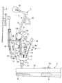
以下、本発明の好ましい実施形態を、図面を参照しながら詳細に説明する。図1は、本発明を適用したアップライトピアノのアクション1、鍵盤2およびハンマー3などを、離鍵状態において示している。なお、以下の説明では、演奏者側から見たときのアップライトピアノの手前側を「前」、奥側を「後」として説明する。
Hereinafter, preferred embodiments of the present invention will be described in detail with reference to the drawings. FIG. 1 shows an
鍵盤2は、アップライトピアノの左右方向に並んだ多数の鍵2a(1つのみ図示)によって構成されている。また、各鍵2aは、前後方向(図1の左右方向)に延び、その中央において、棚板(図示せず)上の筬5に立設されたバランスピン5aに回動自在に支持されている。また、筬5の後方にはバックレール6が設けられており、各鍵2aの後端部は、このバックレール6に載置されている。
The keyboard 2 is composed of a number of
棚板の左右の端部には、アクションブラケット(図示せず)がそれぞれ設けられている。アクション1は、鍵盤2の後端部の上方に配置され、両アクションブラケットの間に設けられている。アクション1は、ウィッペン11、ジャック13およびバット15などを有しており、これらは、鍵2aごとに設けられている(いずれも1つのみ図示)。
Action brackets (not shown) are respectively provided on the left and right ends of the shelf board. The
左右のアクションブラケットの間には、センターレール29(静止部材)およびハンマーレール30などが渡されている。センターレール29は、例えばアルミニウムの押出し成形品で構成され、所定の一定の断面形状を有しており、左右のアクションブラケットに固定されている。また、このセンターレール29の下端部にはウィッペンフレンジ12が、上端部にはバットフレンジ17およびダンパーフレンジ28が、それぞれ鍵2aごとにねじ止めされている(いずれも1つのみ図示)。ウィッペン11は、後端部において、ウィッペンフレンジ12に回動自在に支持されている。また、バット15は、ハンマー3などとともにハンマー組立て品4を一体に構成しており、その下端部において、バットフレンジ17にセンターピン15dを介して回動自在に支持されている。
A center rail 29 (stationary member), a
ウィッペン11は、例えば合成樹脂によって所定の形状に形成されており、その前部から下方に突出するヒール部11aを有し、対応する鍵2aの後端部に設けたキャプスタンボタン2bに、ヒール部11aを介して載置されている。また、ウィッペン11の上面前端部には、バックチェックワイヤ18aが立設されており、その先端部にバックチェック18が取り付けられている。また、ウィッペン11の上面の後端部には、後述するダンパー25を駆動するためのスプーン19が立設されている。
The
ジャック13は、例えば合成樹脂の成形品で構成されており、前後方向に延びる基部13aと、基部13aの後端部から上方に延びるハンマー突上げ部13bを有している。ジャック13は、その基部13aとハンマー突上げ部13bとの角部において、ウィッペン11の中央に、ピン状の支点13cを介して回動自在に支持されている。また、基部13aとウィッペン11の間には、コイルばねで構成されたジャックスプリング14が設けられている。
The
また、図2に示すように、センターレール29の前面には、バットフレンジ17のすぐ下側の位置に、ジャック13ごとにストッパ31が設けられている(1つのみ図示)。各ストッパ31は、ねじ部31a、およびこれと一体の基部31bを有しており、センターレール29にねじ部31aをねじ込むことによって取り付けられている。基部31bは、例えば円板状に形成され、隣接するストッパ31と干渉しないような所定の径を有している。基部31bの前面には、フェルト31cが例えば両面テープで貼り付けられている。フェルト31cは、基部31bと同じ径の円板状に形成され、所定の厚さを有しており、その前面が接触面31dになっている。 センターレール29へのストッパ31の取付け角度およびねじ込み量は、離鍵状態において、ジャック13のハンマー突上げ部13bの後面がストッパ31の接触面31dに面接触するように、設定されている。本実施形態では、ストッパ31は、センターレール29に対して若干、傾いた状態で取り付けられている。以上のようなセンターレール29およびストッパ31によって、本実施形態のジャック静止装置10が構成されている
As shown in FIG. 2, a
また、センターレール29には、複数のレギュレティングブラケット21が、左右方向に互いに間隔を隔てて設けられており(1つのみ図示)、各レギュレティングブラケット21は、それに対応する互いに隣接するストッパ31,31の間、およびジャック13,13の間を通って前方に延びている。レギュレティングブラケット21の前端部には、左右方向に延びるレギュレティングレール22が取り付けられており、その下面には、レギュレティングボタン20が、レギュレティングスクリュー22aによって鍵2aごとに取り付けられている。各レギュレティングボタン20は、対応するジャック13の基部13aに上方から対向している。
The
また、バット15は、バット本体15a、バットスキン15bおよびバットフェルト16などを有している。バットフェルト16は、バット本体15aの前面の下端部に貼り付けられており、ブロック状に形成されている。また、バットスキン15bは、バットフェルト16の上側に隣接し、バット本体15aに貼り付けられている。また、バット本体15aは、例えば合成樹脂で構成され、所定の形状を有し、センターピン15dを介してバットフレンジ17に回動自在に取り付けられている。また、バット本体15aとバットフレンジ17の間には、バットスプリング15gが設けられており、それにより、ハンマー組立て品4は、図1の時計方向に付勢されている。また、バット本体15aには、前方に延びるキャッチャーシャンク23aが設けられており、その前端部にはキャッチャー23が設けられていて、前方のバックチェック18に対向している。
The
ハンマー3は、各バット15の上面に立設され、上方に延びるハンマーシャンク3a、およびその上端部に設けられたハンマーヘッド3bを有しており、ハンマーヘッド3bは、後方に張られた弦Sに対向している。また、センターレール29の後方には、ダンパー25が、鍵2aごとにダンパーフレンジ28に回動自在に取り付けられている。
The
以上の構成により、ジャック13は、離鍵状態においては、所定の静止位置に静止した状態でハンマー組立て品4を支持している。この状態では、ジャック13のハンマー突上げ部13bが、その後面の中央において、ストッパ31の接触面31dに面接触し、それにより、ジャック13はストッパ31に係止されている。また、ハンマー突上げ部13bの上面が、バット15のバットスキン15bの下面に係合するとともに、ハンマー突上げ部13bの上端部の角部が、バットフェルト16の前面に当接している。
With the above configuration, the
以下、上述したアップライトピアノの押鍵の開始から終了までの一連の動作について説明する。演奏者により、図1に示す離鍵状態から鍵2aが押鍵されると、その後端部に載置されたウィッペン11は、鍵2aによって突き上げられることにより、上方(反時計方向)に回動する。このウィッペン11の回動に伴い、ウィッペン11に設けられたジャック13などが一緒に上方に移動し、ハンマー組立て品4は、バット15を介してジャック13のハンマー突上げ部13bで突き上げられることにより、後方の弦Sに向かって反時計方向に回動する。
Hereinafter, a series of operations from the start to the end of the above-described upright piano key pressing will be described. When the player presses the key 2a from the key-released state shown in FIG. 1, the
鍵2aがさらに回動すると、ジャック13の基部13aの前端部が、レギュレティングボタン20に下方から当接することにより、ジャック13は、上方への移動が阻止されることによって、ウィッペン11に対して時計方向に回動する。そして、鍵2aがさらに回動したときに、ハンマー突上げ部13bがバット15から前方に外れ、ジャック13がハンマー組立て品4から離脱する(レットオフ)。その際、鍵2aのタッチ重さからハンマー組立て品4の重量分が失われ、タッチ重さが急激に減少することによって、演奏者にレットオフ感が付与される。
When the key 2a further rotates, the front end portion of the
ハンマー組立て品4は、ジャック13が離脱した後も慣性によって回動し、ハンマー3が弦Sを打弦し、振動させることによって、ピアノ音を発生させる。そして、ハンマー組立て品4は、弦Sの反発力と、バットスプリング15gの付勢力によって、時計方向へ復帰回動する。
The hammer assembly 4 is rotated by inertia even after the
押鍵が終了し、鍵2aが離鍵されるのに伴い、鍵2aおよびアクション1などは、押鍵時と逆方向に復帰回動する。具体的には、ウィッペン11が復帰回動するのに伴い、ジャック13は、ウィッペン11とともに下方に移動し、その途中で基部13aがレギュレティングボタン20から外れるのに伴い、ジャックスプリング14gの付勢力によって、反時計方向に復帰回動する。
As the key depression is completed and the key 2a is released, the key 2a, the
一方、ハンマー組立て品4は、バットスプリング15gの付勢力によって時計方向にさらに復帰回動する。その途中で、復帰回動中のジャック13のハンマー突上げ部13bが、バット15の下側に入り込むとともに、ハンマー突上げ部13bの後面が、ストッパ31の接触面31dに面接触状態で当接する。これにより、ジャック13は、ストッパ31に係止され、最終的に静止位置に静止する。また、この状態では、ハンマー突上げ部13bの上端部が、バットフェルト16の前面に当接している。
On the other hand, the hammer assembly 4 is further rotated back in the clockwise direction by the urging force of the
以上のように、本実施形態によれば、ジャック13が復帰回動する際に、不動のセンターレール29に設けたストッパ31でジャック13を係止し、静止させるので、従来のように、回動可能なバット15のバットフェルト16で静止させる場合よりも、ジャック13を所定の静止位置に精度良く位置決めし、静止させることができる。その結果、ジャック13の静止位置が適正位置に保たれるので、ジャック13およびハンマー3の適正な動作を確保でき、それにより、鍵2aのタッチ感や連打性などを良好に維持することができる。
As described above, according to the present embodiment, when the
また、ジャック13のハンマー突上げ部13bがストッパ31の接触面31dに面接触するので、そのときにジャック13からストッパ31に作用する荷重が、ストッパ31の接触面31d全体に均等に分散される。それにより、ストッパ31の厚さの変化を抑制できる結果、ジャック13の静止位置を長期間、適正位置に保つことができる。
Further, since the hammer push-up
また、センターレール29は、ジャック13の後方に隣接して配置されている。したがって、このようなセンターレール29を利用することにより、不動であるという静止部材の条件を満たしながら、ストッパ31を適切に設置することができる。また、既存のセンターレール29を静止部材として兼用することにより、別個の静止部材は不要になるので、製造コストを削減することができる。
The
また、ストッパ31は、鍵2aごとに設けられるとともに、センターレール29へのねじ込みによって取り付けられている。したがって、ストッパ31のねじ込み量を調整することにより、ストッパ31の前後方向の位置を微調整でき、それにより、ジャック13の静止位置を、鍵2aの良好なタッチ感や連打性を得ることができる最適な位置に鍵2aごとにきめ細かく設定することができる。また、ジャック13が柔軟性を有するストッパ31のフェルト31cに当接するので、この当接時の衝撃を十分、緩和できるとともに、雑音の発生を抑制することができる。
The
なお、本発明は、上述した実施形態に限定されることなく、種々の態様で実施することができる。例えば、実施形態では、ジャック13が当接するストッパ31の部位にフェルトを用いているが、フェルトに代えて、他の適当な任意の材料を採用することができる。例えば、柔軟性に加えて、湿度変化や繰り返し作用するジャック13からの反復荷重に対しての寸法安定性や耐摩耗性を有する材料、例えば、フッ素樹脂の繊維などの化学繊維を用いることが好ましく、それにより、ストッパ31の厚さの変化をさらに抑制でき、ジャック13の静止位置を、より長期間、適正位置に保つことができる。
In addition, this invention can be implemented in various aspects, without being limited to the embodiment described above. For example, in the embodiment, felt is used for the portion of the
また、実施形態では、ストッパ31を鍵2aごとに設けたが、例えば左右方向に延びるストッパをすべての鍵2aに対して、あるいは複数の鍵2aごとに設けてもよい。その他、細部の構成を、本発明の趣旨の範囲内で適宜、変更することが可能である。
In the embodiment, the
2a 鍵
3 ハンマー
13 ジャック
10 ジャック静止装置
29 センターレール(静止部材)
31 ストッパ
31d 接触面
31
Claims (3)
不動の静止部材と、
当該静止部材に設けられ、離鍵に伴って復帰回動する前記ジャックを係止することによって、前記所定の静止位置に静止させるストッパと、
を備えていることを特徴とするアップライトピアノのジャック静止装置。 A jack stationary device of an upright piano that pushes a hammer in accordance with a key depression and rotates the jack to be stationary at a predetermined stationary position in a key release state,
An immobile stationary member;
A stopper provided on the stationary member and locked at the predetermined stationary position by locking the jack that returns and rotates when the key is released;
An upright piano jack stationary device.
The upright piano jack stationary apparatus according to claim 1, wherein the stationary member is a center rail.
Priority Applications (1)
| Application Number | Priority Date | Filing Date | Title |
|---|---|---|---|
| JP2006062577A JP5020522B2 (en) | 2006-03-08 | 2006-03-08 | Upright piano jack stationary |
Applications Claiming Priority (1)
| Application Number | Priority Date | Filing Date | Title |
|---|---|---|---|
| JP2006062577A JP5020522B2 (en) | 2006-03-08 | 2006-03-08 | Upright piano jack stationary |
Publications (2)
| Publication Number | Publication Date |
|---|---|
| JP2007240837A JP2007240837A (en) | 2007-09-20 |
| JP5020522B2 true JP5020522B2 (en) | 2012-09-05 |
Family
ID=38586448
Family Applications (1)
| Application Number | Title | Priority Date | Filing Date |
|---|---|---|---|
| JP2006062577A Expired - Fee Related JP5020522B2 (en) | 2006-03-08 | 2006-03-08 | Upright piano jack stationary |
Country Status (1)
| Country | Link |
|---|---|
| JP (1) | JP5020522B2 (en) |
Family Cites Families (9)
| Publication number | Priority date | Publication date | Assignee | Title |
|---|---|---|---|---|
| DE107352C (en) * | ||||
| FR371986A (en) * | 1906-02-06 | 1907-03-21 | Adolphe Seeger | Improvements to piano mechanics |
| US2141728A (en) * | 1938-01-31 | 1938-12-27 | Stein Charles Frederick | Upright piano |
| JPS58100186A (en) * | 1981-12-09 | 1983-06-14 | 鈴木 淳一 | Action mechanism for piano |
| JPS594596U (en) * | 1982-06-30 | 1984-01-12 | 株式会社河合楽器製作所 | piano action mechanism |
| JPS5917497U (en) * | 1982-07-26 | 1984-02-02 | 株式会社河合楽器製作所 | Upright piano action |
| JPS5917496U (en) * | 1982-07-26 | 1984-02-02 | 株式会社河合楽器製作所 | Upright piano action |
| JPH05323953A (en) * | 1992-05-22 | 1993-12-07 | Yamaha Corp | Action of upright piano |
| JPH07334150A (en) * | 1994-06-13 | 1995-12-22 | Yamaha Corp | Keyboard instrument |
-
2006
- 2006-03-08 JP JP2006062577A patent/JP5020522B2/en not_active Expired - Fee Related
Also Published As
| Publication number | Publication date |
|---|---|
| JP2007240837A (en) | 2007-09-20 |
Similar Documents
| Publication | Publication Date | Title |
|---|---|---|
| JP5298534B2 (en) | Action mechanism | |
| JP5412859B2 (en) | Upright action and keyboard instrument | |
| JP5488985B2 (en) | Upright piano type action | |
| JP2003280657A (en) | Upright type keyboard musical instrument | |
| EP2461319B1 (en) | Action of upright piano | |
| CN101017662B (en) | Jack motion-restricting device for upright piano | |
| JP5020522B2 (en) | Upright piano jack stationary | |
| JP5886618B2 (en) | Electronic keyboard instrument keyboard device | |
| JP3270693B2 (en) | Keyboard device | |
| JP2006285175A (en) | Piano action | |
| JP4769445B2 (en) | Upright piano action | |
| JP2008090168A (en) | Upright piano damper device | |
| JP2005241887A (en) | Keyboard device of electronic keyboard musical instrument | |
| JP2007108661A (en) | Upright piano action | |
| JPH10133649A (en) | Electronic musical instrument keyboard device | |
| US12542118B2 (en) | Keyboard device for keyboard instrument | |
| JP5963415B2 (en) | Electronic keyboard instrument hammer device | |
| JP3519549B2 (en) | Keyboard capstan adjustment device and keyboard device | |
| JP3256447B2 (en) | Keyboard device | |
| JP3420005B2 (en) | Keyboard device | |
| JP2025148982A (en) | Keyboard device for keyboard instruments | |
| CN120708573A (en) | Keyboard device for keyboard musical instrument | |
| JP2007218958A (en) | Upright piano bridle tape mounting structure | |
| WO2013108382A1 (en) | Damper device for upright piano | |
| JP2008102209A (en) | Upright piano action |
Legal Events
| Date | Code | Title | Description |
|---|---|---|---|
| A621 | Written request for application examination |
Free format text: JAPANESE INTERMEDIATE CODE: A621 Effective date: 20090120 |
|
| A977 | Report on retrieval |
Free format text: JAPANESE INTERMEDIATE CODE: A971007 Effective date: 20110629 |
|
| A131 | Notification of reasons for refusal |
Free format text: JAPANESE INTERMEDIATE CODE: A131 Effective date: 20110802 |
|
| TRDD | Decision of grant or rejection written | ||
| A01 | Written decision to grant a patent or to grant a registration (utility model) |
Free format text: JAPANESE INTERMEDIATE CODE: A01 Effective date: 20120515 |
|
| A01 | Written decision to grant a patent or to grant a registration (utility model) |
Free format text: JAPANESE INTERMEDIATE CODE: A01 |
|
| A61 | First payment of annual fees (during grant procedure) |
Free format text: JAPANESE INTERMEDIATE CODE: A61 Effective date: 20120613 |
|
| R150 | Certificate of patent or registration of utility model |
Free format text: JAPANESE INTERMEDIATE CODE: R150 |
|
| FPAY | Renewal fee payment (event date is renewal date of database) |
Free format text: PAYMENT UNTIL: 20150622 Year of fee payment: 3 |
|
| LAPS | Cancellation because of no payment of annual fees |