JP5019407B2 - Control of receiver immunity to interference by controlling linearity - Google Patents
Control of receiver immunity to interference by controlling linearity Download PDFInfo
- Publication number
- JP5019407B2 JP5019407B2 JP2002518637A JP2002518637A JP5019407B2 JP 5019407 B2 JP5019407 B2 JP 5019407B2 JP 2002518637 A JP2002518637 A JP 2002518637A JP 2002518637 A JP2002518637 A JP 2002518637A JP 5019407 B2 JP5019407 B2 JP 5019407B2
- Authority
- JP
- Japan
- Prior art keywords
- noise amplifier
- low noise
- interference
- level
- linearity
- Prior art date
- Legal status (The legal status is an assumption and is not a legal conclusion. Google has not performed a legal analysis and makes no representation as to the accuracy of the status listed.)
- Expired - Fee Related
Links
Images


Classifications
-
- H—ELECTRICITY
- H04—ELECTRIC COMMUNICATION TECHNIQUE
- H04B—TRANSMISSION
- H04B1/00—Details of transmission systems, not covered by a single one of groups H04B3/00 - H04B13/00; Details of transmission systems not characterised by the medium used for transmission
- H04B1/06—Receivers
- H04B1/10—Means associated with receiver for limiting or suppressing noise or interference
- H04B1/109—Means associated with receiver for limiting or suppressing noise or interference by improving strong signal performance of the receiver when strong unwanted signals are present at the receiver input
-
- H—ELECTRICITY
- H04—ELECTRIC COMMUNICATION TECHNIQUE
- H04B—TRANSMISSION
- H04B1/00—Details of transmission systems, not covered by a single one of groups H04B3/00 - H04B13/00; Details of transmission systems not characterised by the medium used for transmission
- H04B1/06—Receivers
- H04B1/10—Means associated with receiver for limiting or suppressing noise or interference
- H04B1/1027—Means associated with receiver for limiting or suppressing noise or interference assessing signal quality or detecting noise/interference for the received signal
Abstract
Description
【0001】
【発明の属する技術分野】
本発明は、一般に無線通信に関する。特に本発明は、通信の受信機の、干渉に対するイミュニティー(immunity)の改良に関する。
【0002】
【従来の技術】
多様な型のセルラ電話システムが稼動中である。これらのシステムは、高度な移動電話システム(AMPS)、並びに、2つのディジタルセルラシステム、即ち、時分割多重接続(TDMA)及び符号分割多重接続(CDMA)、を含む。
【0003】
セルラシステムは、一般に、地理的な領域をカバーする(covering)セルの中心に多重アンテナを設置することによって運営する。AMPSのセルはCDMAのセルとは別個で異なっているので、各システムのセルは重なり合っている。これは、一方のシステムのセルのためのアンテナが他方のシステムのセルに設置されることを起こりそうにする。同様に、特定のシステム(例えば、AMPS、CDMA、TDMA)の内では、与えられた地域内に少なくとも2つのサービスプロバイダ(service provider)がある。これらのプロバイダは、しばしば、競争者とは異なる地理的位置にセルを配置することを選択する。従って、システム‘A’上の電話機が、システム‘B’のセルに接近している一方、最も近いシステム‘A’のセルから遠く離れているかもしれない、という状況がある。この状況は、強力なマルチトーン(multi‐tone)の干渉下で所望の受信信号が弱いかもしれないことを意味する。
【0004】
システムアンテナを混合することは、CDMAシステムのような一つのシステムに登録され、且つAMPSアンテナのような他方のシステムのアンテナの近くを移動(travel)するような移動局について問題を引起し得る。この場合において、AMPSアンテナからの信号は、移動局のAMPSセルとの接近又はAMPS順方向リンク信号のより高いパワーのために、移動局によって受信されているCDMA信号と干渉し得る。これは、‘電波妨害(jamming)’として技術的に参照されている。
【0005】
AMPSシステムにおいて、搬送波(carrier)が故意でなく競争者のシステムを‘妨害(jam)’する場合がしばしばある。セルラ搬送波の目標の1つは、セルを大地に近接してか又は彼らのユーザの近くに配置し、各チャンネルについてFCC電力限界(FCC power limit)を放射(radiate)することによって、彼らのシステムの全てのユーザに高い信号対雑音比を提供することにある。この手法は、競争者のシステムを干渉することを犠牲にして、1つの搬送波のシステムに、より良好な信号品質を提供する。
【0006】
干渉又は電波妨害に対する受信機のイミュニティーを改善するための1つの方法は、受信機への電流を増加させることである。しかしながら、移動局はバッテリー電力に頼っているので、これは実際的な解決法ではない。電流を増加させることは、バッテリーをより急速に放出させ、これによって移動局の通話時間及び待機時間を減少させるだろう。さらに、典型的に検出器は電波妨害信号の存在を検出するために使用される。しかしながら、電波妨害信号が検出され、受信機の線形性が増加した時には、電波妨害信号は最早存在しないかもしれない。
【0007】
この結果として、電力消費を大きく増加させることなく、干渉に対する移動局のイミュニティーを急速に制御することが必要となる。
【0008】
【発明の概要】
本発明は、移動局の受信機における低雑音増幅器の線形性の制御を提供する。これは、干渉に対する所望のレベルのイミュニティーを提供する一方、受信機の平均電流消費を減少させる。バッテリー電力の装置において、電流消費を減少させることは、通話時間及び待機時間を増加させる効果を持つ。
【0009】
本発明は、低雑音増幅器の線形性を制御するための方法を包含する。低雑音増幅器は、最初にイネーブル(enabled)される。それから、予測された干渉のレベルが受入れ可能なビット誤り率又は他の信号誤り測定値を生じるかどうかが決定される。
【0010】
予測されたレベルの干渉が受入れ不可能であったら、低雑音増幅器は、高いレベルの線形性に調節される。予測された干渉のレベルが受入れ可能ならば、低雑音増幅器は、低いレベルの線形性に設定される。
【0011】
【発明の実施の形態】
本発明は、制御信号に応答して、予測されたレベルの干渉に対する異なるレベルのイミュニティーを提供する。電流消費は、減少されたイミュニティーが所望のレベルの性能(例えば、ビット誤り率)を提供するとき、低雑音増幅器(LNA)の線形性を減少することによって改善される。LNAの線形性を増加させることは、より大きいイミュニティーが要求されるとき、干渉に対する受信機のイミュニティーを増加させる。この線形性制御は、予測された又は予期されたレベルの干渉に基づく。
【0012】
図1は、本発明のLNA(100)の好ましい実施形態のブロック図を示す。LNAは、入力された受信信号(101)を具備する。好ましい実施形態において、この受信信号(101)は、LNA(100)が動作しているシステムのための無線周波数のものである。
【0013】
増幅された受信信号(105)は、LNAから出力される。受信信号(101)の増幅のレベルは、本発明の電流制御信号(110)及びイネーブル/バイパス信号(115)に依存する。
【0014】
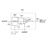
図2は、本発明のイネーブル/バイパス機能の例を図示する。LNA(100)に組入れられたイネーブル/バイパス機能は、デマルチプレクサ(205)を具備する。受信信号(101)は、デマルチプレクサ(205)への入力信号である。イネーブル/バイパス信号(115)は、デマルチプレクサ(205)の2つの出力(210及び215)のうちの1つを選択する。第1の出力(210)は、本発明のLNA機能(225)をバイパス(bypasses)する。第2の出力(215)は、本発明のLNA機能(225)への入力である。
【0015】
図1に示された実施形態におけるように、電流制御信号(110)は、LNA機能(225)へ入力される。増幅された受信信号(105)は、LNA機能(225)から出力される。
【0016】
図2に示されたイネーブル/バイパス機能は、単に図示を目的としたものであり、このようなイネーブル/バイパス機能の1つの例に過ぎない。多くの異なる切替え(switching)の筋書きが、この機能を行うことができる。本発明は、これらの種々の筋書きのどの1つにも限定されない。
【0017】
図3は、電流制御信号によってLNAの線形性を制御するための、本発明の方法のフローチャートを示す。この実施形態において、LNAは、階段関数(step function)の電流制御信号によって、低いか又は高い線形性のいずれかに設定される。
【0018】
この方法は、イネーブルされているLNAで始まる(ステップ301)。このイネーブルは、図2に示されているように、又はどのような他のイネーブル手段でも使用して行われることができる。
【0019】
干渉のレベルは、移動局の所望の性能レベルにとってそれが受入れ可能だろうかどうかを決定するために予測される(ステップ305)。干渉のレベルは、多くの要因、移動局の位置及び移動局が動作している周波数(即ち、どのサービスプロバイダを使用しているか)、移動局へ送られる電力制御命令、移動局の現在の動作モード、受信信号の強度、送信される信号の強度、現在の干渉のレベル、受入れ可能な干渉のレベル、及びLNAがイネーブルされているか又はバイパスされているかどうか、に基づいて、予測されることができる。
【0020】
予測されたレベルの干渉が受入れ可能かどうかは、上記の諸要因のうちの1つ又はその組み合わせに基づいてもよい。これらの要因のいくつかは、等しく重視されなくてもよい。例えば、受入れ可能な干渉のレベルは、干渉レベルの予測において他の要因よりも重要であるから、これが他の要因よりもより重視されることが考えられるかもしれない。
【0021】
第1のセルラシステムがある地理的位置に設置されるとき、第2のセルラシステムが第1のセルラシステムのいくつか又は全てのチャンネルと干渉する周波数で動作することを知らされるかもしれない。その上に、緊急無線帯域のような、その地域において他の干渉をする送信が、第1のセルラシステムのいくつかの又は全てのチャンネルと干渉を引起すことを、知らされるかもしれない。
【0022】
干渉のレベルの予測における他の要因は、移動局によって受信される電力制御命令である。移動局が基地局から多くの“電力増加”命令を受信するときは、これは、高い干渉の地域へ進入しつつあることを示しているかもしれない。
【0023】
さらに、干渉のレベルの予測における他の要因は、移動局の動作モード(例えば、AMPS、CDMA)である。動作モードは、移動局が動作している周波数を含む。上記で議論したように、ある周波数帯域があるレベルの干渉を受けることは、知られ得る。それ故に、移動局がCDMAモードにあり、且つその地域においてAMPS信号がCDMA信号と干渉することが知られているならば、これは、本発明の方法によって干渉のレベルを予測するために、使用される。
【0024】
受信或いは送信された信号の強度は、干渉のレベルの予測における他の指標である。受信信号の強度は、受信された電力の周期的なサンプルを、所定の閾値、又は非バイナリ線形性(non-binary linearity)の場合は諸閾値と比較することによって、干渉のレベルを表示する。送信信号の強度は、送信電力の周期的なサンプルを所定の閾値、又は諸閾値と比較することによって、干渉のレベルを表示する。
【0025】
干渉は、内部で又は外部で発生し得る。移動局の送信器は、内部の干渉を発生させ得る。このような供給源(source)からの予測可能な瞬間的な干渉の間、例えば半2重(half-duplex)送信の間、干渉は受入れ可能であり得る。この場合において、内部で発生した干渉は、現在の動作モード及び/又は送信された信号の強度の組み合わせに基づいて、予測されることができる。外部で発生した干渉は、続いて図5の実施形態に関連して示され議論される方法のような、種々の方法によって検出されることができる。
【0026】
さらに、干渉のレベルの予測における他の指標は、LNAがイネーブルされたか又はバイパス/ディスエーブル(bypassed/disabled)されたかどうかである。LNAがディスエーブル(disabled)されたとき、LNAの線形性の増加は、必要でない。
【0027】
再び図3の方法を参照すると、干渉のレベルが、干渉の所定の閾値を下回るだろうと決定されれば、LNAの“低い”線形性モードが選択される(ステップ310)。1つの実施形態において、これは、電流制御信号を所定の固定された“低い”レベルに設定することによって達成され得る。
【0028】
“低い”線形性モードで、LNAを動作させるために要求される電流制御信号は、実験によって決定されてもよい。同様に、予測された干渉のレベルで動作する受信機の十分な性能のために、LNAによって要求される線形性のレベルもまた、実験によって決定されてもよい。
【0029】
移動局の適切な動作のために受入れ可能な、所定の干渉の閾値は、移動局の設計の間に決定される。この閾値は、移動局の設計とともに変化するので、どのような1つの範囲にあるとも明示されることはできない。好ましい実施形態において、受入れ可能な動作のレベルは、増幅された受信信号のシンボル誤り率(SER)によって決定される。他の実施形態は、他の形式の誤り決定を使用する。
【0030】
予測された干渉のレベルが、所定の干渉の閾値より上にあるだろうと決定される場合、LNAの“高い”線形性モードが選択される(ステップ315)。低い線形性モードにおけるように、“高い”線形性モードでLNAを動作させるために要求される電流制御信号は、実験によって決定されてもよい。
【0031】
移動局は、動的に変化する環境において動作しているので、一旦LNAの線形性モードが設定されると(ステップ310又は315)、LNAの線形性を変化させることを要求する何かが変化したかどうかを決定するために(ステップ320)、種々の所定の基準がチェックされる。これらの基準は、移動局のモードが変化したかどうか、LNAがイネーブルされたか若しくはディスエーブルされたかどうか、又は周期的なタイマーが満了したかどうか、を含む。この方法は、進行する前に、これらの基準の1つが変化するのを待つ(ステップ320)。
【0032】
移動局のモードが変化した場合、新しい環境に進入し、且つそれ故に遭遇する干渉のレベルは、異なるだろう。上記で議論したように、これは、異なるレベルのLNA線形性を要求するかもしれない。
【0033】
LNAがディスエーブルされた場合、LNAの線形性を変化させる試みは、何の効果も持たない。さらに、ある長さの時間の後、移動局は、他の干渉のレベルに進入してしまい、且つLNAの線形性は、変化されるべきであることが、想定されることができる。これは、LNAの線形性の最後の調節からの時間を決定することによって、チェックされることができる。この時間を閾値の時間と比較することは、干渉レベルが再チェックされるべきときの表示を与える。この閾値の時間は、異なる状況に対して変化する。ある状況は、数マイクロ秒毎に周期的なタイマーチェックを要求するかもしれない。他の状況は、100ミリ秒毎の周期的なチェックを要求するかもしれない。
【0034】
再び図3を参照すると、LNAがディスエーブルされていないと決定された場合(ステップ325)、方法は、干渉のレベルが受入れ可能か否かの予測に戻る(ステップ305)。LNAがディスエーブルされていると決定された場合(ステップ325)、方法はそれから、LNAがイネーブルされるのを待つ(ステップ330)。これが起こったとき、方法は、LNAがイネーブルされた方法における最初のステップへ戻る(ステップ301)。
【0035】
図4は、本発明の他の実施形態の方法のフローチャートを示す。図3の実施形態は電流制御信号として階段関数を使用したが、図4の実施形態は、電流制御信号として連続的に可変の信号を使用する。
【0036】
図4の実施形態は、LNAがイネーブルされ(ステップ401)、予測されたレベルの干渉の受入れ可能性について点検される(ステップ405)点において、図3に図示された方法と同様である。予測された干渉レベルが受入れ可能な場合、線形性は、低い線形性モードに設定される(ステップ410)。
【0037】
予測された干渉レベルが受入れ不可能ならば、所望の性能レベルが達成されるまで、線形性モードは、連続的に変化する(ステップ415)。好ましい実施形態において、所望の性能レベルは、LNAによって出力される、増幅された受信信号の誤り率をモニタリング(monitoring)することによって決定される。誤り決定が所定の閾値に到達するとき、電流制御信号は、次ぎの決定が要求されるまで、この点で維持される。他の実施形態は、所望の性能レベルを決定するために、及び所望の性能レベルを達成するための電流制御信号を調節するために、他の方法を使用する。
【0038】
一旦LNAの線形性モードが設定されたとすると、方法は、満了する周期的なタイマーチェックと共に、モード変化、LNAイネーブルの変化、のいずれかを待つ(ステップ420)。LNAがディスエーブルされていた場合(ステップ425)、方法は、LNAがイネーブルされるのを待つ(ステップ430)。LNAがディスエーブルされていなかった場合(ステップ425)、方法は、干渉レベルが受入れ可能かどうかの予測に戻る(ステップ405)。
【0039】
図5のブロック図は、干渉に対する受信機のイミュニティーを制御するための本発明の装置を組入れた移動局の1つの実施形態を示す。この実施形態は、図2に示されたデマルチプレクサの代りに、LNA機能(500)をイネーブル/バイパスするための切替え機能(switching function)(505)を使用する。図5の装置は、単に図示するためのものである。本発明は、他の受信機に組入れられることができる。
【0040】
この実施形態は、無線信号を受信し、且つ送信するアンテナ(575)を含む。無線(radio)における送信経路(565)は、送信された信号から受信信号を分離するデュプレクサ(duplexer)(560)を通してアンテナ(575)へ結合される。
【0041】
デュプレクサ(560)からの受信信号は、LNA(500)へ入力される。LNA(500)からの増幅された信号は、バンドパスフィルタ(bandpass filter)(515)へ出力される。
【0042】
LNA(500)は、バイパス経路(506)へ結合されたスイッチ(505)によってバイパスされることができる。バイパス経路(506)は、スイッチ(505)とともに、スイッチ(505)が閉じられたときにLNA(500)がディスエーブルされるようなLNA(500)の周囲の経路を提供する。
【0043】
スイッチ(505)は、移動局の制御器(510)によって制御される。制御器(510)は、本発明の方法に従って、LNA(500)をイネーブルするか、又はディスエーブルする。制御器(510)は、マイクロプロセッサ、マイクロコントローラ、又は図3及び図4に示された諸方法を動作するいくつかの他のタイプの制御回路であってもよい。
【0044】
バンドパスフィルタ(515)が受信信号を濾波した後、濾波された信号は、移動局の残りが使用するために、低い中間周波数(IF)へダウンコンバート(down‐convert)される。ダウンコンバージョン(down‐conversion)は、電圧制御された発振器(530)を駆動するフェーズロックドループ(phase locked loop)(535)によって設定された周波数を持つ他の信号を、受信信号へ混合すること(520)によってなされる。この信号は、ミキサ(520)へ入力される前に増幅される(525)。
【0045】
ミキサ(520)からのダウンコンバートされた信号は、バックエンド(back end)AGC(540及び545)へ入力される。このAGCは、技術的によく周知のように、移動局によってクローズドループ(closed loop)電力制御のために使用される。
【0046】
図5の装置において、LNA(500)への電流制御信号(550)は、移動局の制御器(510)によって生成される。1つの実施形態において、制御器(510)は、図3に示された方法によって要求されるような階段関数を生成する。他の実施形態において、制御器(510)は、図4に示された方法によって要求されるような連続した制御信号(550)を生成する。制御器(510)は又、以前に議論したように、現在の干渉のレベルを検出する方法として、AGC(540及び545)からの出力信号をモニタリングすることもできる。この現在の干渉のレベルは、上記に議論したイネーブル/バイパススイッチ(505)を制御する、及び連続的に可変の電流制御信号(550)を発生させる他の要因とともに使用される。この仕方で、制御器(510)は、種々のレベルの干渉を含む異なる環境におけるLNA(500)の線形性を制御する。
【0047】
好ましい実施形態の移動局はセルラ電話機であるが、本発明の方法及び装置は、他のタイプの移動局に組入れられることができる。例えば、移動局は、ラップトップコンピュータに組込まれたモデム、無線周波数信号を受信する能力を有するパーソナルデジタルアシスタント(personal digital assistant)、又は予測された干渉のレベルに応答してその線形性を変化する受信機から利益を得るであろう、他のいかなるタイプの通信装置であってもよい。
【0048】
要約すると、本発明は、他のシステムからの無線周波数干渉に対する移動局のイミュニティーを増加させると同時に、移動局が異なるシステムのアンテナの近くに移動できるようする。これは、移動局の通話時間又は待機時間に影響を与えることなく達成される。先行技術のシステムは、電力を犠牲にしてより高い線形性のLNAを使用したか、又は著しい干渉に遭ったときに働かなかったであろう。
【図面の簡単な説明】
【図1】 図1は、本発明の低雑音増幅器のブロック図を示す。
【図2】 図2は、本発明の低雑音増幅器に従ったイネーブル/バイパス機能の実施形態を示す。
【図3】 図3は、低雑音増幅器の線形性を変化させるための本発明のフローチャートを示す。
【図4】 図4は、本発明の他の実施形態の方法のフローチャートを示す。
【図5】 図5は、本発明の低雑音増幅器を組入れた受信機のブロック図を示す。
【符号の説明】
100…低雑音増幅器、205…デマルチプレクサ、225…LNA機能、506…バイパス経路、510…制御器、515…バンドパスフィルタ。[0001]
BACKGROUND OF THE INVENTION
The present invention generally relates to wireless communications. In particular, the invention relates to improving the immunity to interference of a communication receiver.
[0002]
[Prior art]
Various types of cellular telephone systems are in operation. These systems include advanced mobile telephone systems (AMPS) and two digital cellular systems: time division multiple access (TDMA) and code division multiple access (CDMA).
[0003]
Cellular systems generally operate by installing multiple antennas in the center of a cell that covers a geographical area. Since AMPS cells are separate and different from CDMA cells, the cells of each system overlap. This makes it likely that the antenna for one system cell will be installed in the other system cell. Similarly, within a particular system (eg, AMPS, CDMA, TDMA), there are at least two service providers within a given region. These providers often choose to place cells in a different geographical location than their competitors. Thus, there is a situation where the phone on system 'A' may be approaching the cell of system 'B', but far from the cell of the closest system 'A'. This situation means that the desired received signal may be weak under strong multi-tone interference.
[0004]
Mixing system antennas can cause problems for mobile stations that are registered in one system, such as a CDMA system, and that travel near the antenna of the other system, such as an AMPS antenna. In this case, the signal from the AMPS antenna may interfere with the CDMA signal being received by the mobile station due to the proximity of the mobile station to the AMPS cell or the higher power of the AMPS forward link signal. This is technically referred to as 'jamming'.
[0005]
In AMPS systems, the carrier often unintentionally 'jams' the competitor's system. One goal of cellular carriers is to place cells close to the ground or close to their users and radiate FCC power limits for each channel, thereby increasing their system. Is to provide a high signal-to-noise ratio for all users. This approach provides better signal quality for a single carrier system at the expense of interfering with the competitor's system.
[0006]
One way to improve the immunity of the receiver to interference or jamming is to increase the current to the receiver. However, this is not a practical solution because mobile stations rely on battery power. Increasing the current will cause the battery to discharge more quickly, thereby reducing the mobile station's talk time and standby time. In addition, detectors are typically used to detect the presence of jamming signals. However, when a jamming signal is detected and the receiver linearity increases, the jamming signal may no longer exist.
[0007]
As a result, it is necessary to rapidly control the immunity of the mobile station to interference without greatly increasing power consumption.
[0008]
Summary of the Invention
The present invention provides control of the linearity of a low noise amplifier in a mobile station receiver. This provides the desired level of immunity to interference while reducing the average current consumption of the receiver. In battery powered devices, reducing current consumption has the effect of increasing talk time and standby time.
[0009]
The present invention encompasses a method for controlling the linearity of a low noise amplifier. The low noise amplifier is first enabled. It is then determined whether the predicted level of interference results in an acceptable bit error rate or other signal error measurement.
[0010]
If the expected level of interference is unacceptable, the low noise amplifier is adjusted to a high level of linearity. If the predicted level of interference is acceptable, the low noise amplifier is set to a low level of linearity.
[0011]
DETAILED DESCRIPTION OF THE INVENTION
The present invention provides different levels of immunity to predicted levels of interference in response to control signals. Current consumption is improved by reducing the linearity of the low noise amplifier (LNA) when the reduced immunity provides the desired level of performance (eg, bit error rate). Increasing the linearity of the LNA increases the receiver's immunity to interference when greater immunity is required. This linearity control is based on the predicted or expected level of interference.
[0012]
FIG. 1 shows a block diagram of a preferred embodiment of the LNA (100) of the present invention. The LNA includes an input received signal (101). In the preferred embodiment, this received signal (101) is of radio frequency for the system in which the LNA (100) is operating.
[0013]
The amplified received signal (105) is output from the LNA. The level of amplification of the received signal (101) depends on the current control signal (110) and the enable / bypass signal (115) of the present invention.
[0014]
FIG. 2 illustrates an example of the enable / bypass function of the present invention. The enable / bypass function incorporated in the LNA (100) comprises a demultiplexer (205). The reception signal (101) is an input signal to the demultiplexer (205). The enable / bypass signal (115) selects one of the two outputs (210 and 215) of the demultiplexer (205). The first output (210) bypasses the LNA function (225) of the present invention. The second output (215) is an input to the LNA function (225) of the present invention.
[0015]
As in the embodiment shown in FIG. 1, the current control signal (110) is input to the LNA function (225). The amplified received signal (105) is output from the LNA function (225).
[0016]
The enable / bypass function shown in FIG. 2 is for illustration purposes only and is only one example of such an enable / bypass function. Many different switching scenarios can perform this function. The present invention is not limited to any one of these various scenarios.
[0017]
FIG. 3 shows a flow chart of the method of the present invention for controlling the linearity of the LNA with a current control signal. In this embodiment, the LNA is set to either low or high linearity by a step function current control signal.
[0018]
The method begins with an enabled LNA (step 301). This enabling can be done as shown in FIG. 2 or using any other enabling means.
[0019]
The level of interference is predicted to determine if it will be acceptable for the desired performance level of the mobile station (step 305). The level of interference depends on many factors, the location of the mobile station and the frequency at which the mobile station is operating (ie which service provider is used), the power control command sent to the mobile station, the current operation of the mobile station Predicted based on mode, received signal strength, transmitted signal strength, current interference level, acceptable interference level, and whether LNA is enabled or bypassed it can.
[0020]
Whether the predicted level of interference is acceptable may be based on one or a combination of the above factors. Some of these factors may not be equally important. For example, it may be considered that the level of acceptable interference is more important than other factors in predicting the interference level, so this is more important than other factors.
[0021]
When the first cellular system is installed at a geographical location, it may be informed that the second cellular system operates at a frequency that interferes with some or all channels of the first cellular system. Moreover, it may be informed that transmissions that cause other interference in the region, such as emergency radio bands, cause interference with some or all channels of the first cellular system.
[0022]
Another factor in predicting the level of interference is the power control command received by the mobile station. When the mobile station receives many “increase power” commands from the base station, this may indicate that it is entering an area of high interference.
[0023]
Furthermore, another factor in predicting the level of interference is the mobile station's operating mode (eg, AMPS, CDMA). The operation mode includes the frequency at which the mobile station is operating. As discussed above, it can be known that certain frequency bands experience a certain level of interference. Therefore, if the mobile station is in CDMA mode and AMPS signals are known to interfere with CDMA signals in that area, this is used to predict the level of interference by the method of the present invention. Is done.
[0024]
The strength of the received or transmitted signal is another indicator in predicting the level of interference. The strength of the received signal indicates the level of interference by comparing periodic samples of the received power with a predetermined threshold or thresholds in the case of non-binary linearity. The strength of the transmitted signal indicates the level of interference by comparing periodic samples of transmitted power with predetermined thresholds or thresholds.
[0025]
Interference can occur internally or externally. The mobile station transmitter may generate internal interference. During predictable instantaneous interference from such a source, for example during half-duplex transmission, the interference may be acceptable. In this case, internally generated interference can be predicted based on a combination of the current mode of operation and / or the strength of the transmitted signal. Externally generated interference can subsequently be detected by various methods, such as the method shown and discussed in connection with the embodiment of FIG.
[0026]
Furthermore, another indicator in predicting the level of interference is whether the LNA is enabled or bypassed / disabled. When the LNA is disabled, an increase in LNA linearity is not necessary.
[0027]
Referring again to the method of FIG. 3, if it is determined that the level of interference will be below a predetermined threshold of interference, the “low” linearity mode of the LNA is selected (step 310). In one embodiment, this can be accomplished by setting the current control signal to a predetermined fixed “low” level.
[0028]
The current control signal required to operate the LNA in “low” linearity mode may be determined empirically. Similarly, for sufficient performance of a receiver operating at the predicted level of interference, the level of linearity required by the LNA may also be determined experimentally.
[0029]
The predetermined interference threshold that is acceptable for proper operation of the mobile station is determined during the design of the mobile station. Since this threshold varies with the design of the mobile station, it cannot be specified in any one range. In a preferred embodiment, the level of acceptable operation is determined by the symbol error rate (SER) of the amplified received signal. Other embodiments use other forms of error determination.
[0030]
If it is determined that the predicted level of interference will be above a predetermined interference threshold, the “high” linearity mode of the LNA is selected (step 315). As in the low linearity mode, the current control signal required to operate the LNA in the “high” linearity mode may be determined empirically.
[0031]
Since the mobile station is operating in a dynamically changing environment, once the linearity mode of the LNA is set (step 310 or 315), something that requires changing the linearity of the LNA changes. To determine whether (step 320), various predetermined criteria are checked. These criteria include whether the mobile station's mode has changed, whether the LNA is enabled or disabled, or whether the periodic timer has expired. The method waits for one of these criteria to change before proceeding (step 320).
[0032]
If the mode of the mobile station changes, the level of interference entering the new environment and hence encountered will be different. As discussed above, this may require different levels of LNA linearity.
[0033]
If the LNA is disabled, attempts to change the linearity of the LNA have no effect. Furthermore, after a certain amount of time, it can be assumed that the mobile station has entered another level of interference and the linearity of the LNA should be changed. This can be checked by determining the time since the last adjustment of the linearity of the LNA. Comparing this time with a threshold time gives an indication when the interference level should be rechecked. This threshold time varies for different situations. Some situations may require periodic timer checks every few microseconds. Other situations may require periodic checks every 100 milliseconds.
[0034]
Referring again to FIG. 3, if it is determined that the LNA is not disabled (step 325), the method returns to predicting whether the level of interference is acceptable (step 305). If it is determined that the LNA is disabled (step 325), the method then waits for the LNA to be enabled (step 330). When this happens, the method returns to the first step in the LNA enabled method (step 301).
[0035]
FIG. 4 shows a flowchart of a method according to another embodiment of the present invention. While the embodiment of FIG. 3 uses a step function as the current control signal, the embodiment of FIG. 4 uses a continuously variable signal as the current control signal.
[0036]
The embodiment of FIG. 4 is similar to the method illustrated in FIG. 3 in that the LNA is enabled (step 401) and checked for the acceptability of the predicted level of interference (step 405). If the predicted interference level is acceptable, the linearity is set to a low linearity mode (step 410).
[0037]
If the predicted interference level is unacceptable, the linearity mode changes continuously until the desired performance level is achieved (step 415). In a preferred embodiment, the desired performance level is determined by monitoring the error rate of the amplified received signal output by the LNA. When the error decision reaches a predetermined threshold, the current control signal is maintained at this point until the next decision is required. Other embodiments use other methods to determine the desired performance level and to adjust the current control signal to achieve the desired performance level.
[0038]
Once the linearity mode of the LNA has been set, the method waits for either a mode change, a change in LNA enable, along with a periodic timer check that expires (step 420). If the LNA has been disabled (step 425), the method waits for the LNA to be enabled (step 430). If the LNA has not been disabled (step 425), the method returns to predicting whether the interference level is acceptable (step 405).
[0039]
The block diagram of FIG. 5 shows one embodiment of a mobile station incorporating the apparatus of the present invention for controlling receiver immunity to interference. This embodiment uses a switching function (505) to enable / bypass the LNA function (500) instead of the demultiplexer shown in FIG. The apparatus of FIG. 5 is for illustration only. The present invention can be incorporated into other receivers.
[0040]
This embodiment includes an antenna (575) that receives and transmits radio signals. The radio transmission path (565) is coupled to the antenna (575) through a duplexer (560) that separates the received signal from the transmitted signal.
[0041]
The received signal from the duplexer (560) is input to the LNA (500). The amplified signal from the LNA (500) is output to a bandpass filter (515).
[0042]
The LNA (500) can be bypassed by a switch (505) coupled to a bypass path (506). Bypass path (506), along with switch (505), provides a path around LNA (500) such that LNA (500) is disabled when switch (505) is closed.
[0043]
The switch (505) is controlled by the controller (510) of the mobile station. Controller (510) enables or disables LNA (500) in accordance with the method of the present invention. The controller (510) may be a microprocessor, microcontroller, or some other type of control circuit that operates the methods shown in FIGS.
[0044]
After the bandpass filter (515) filters the received signal, the filtered signal is down-converted to a lower intermediate frequency (IF) for use by the rest of the mobile station. Down-conversion is the mixing of other signals with the frequency set by the phase locked loop (535) driving the voltage controlled oscillator (530) into the received signal ( 520). This signal is amplified (525) before being input to the mixer (520).
[0045]
The down converted signal from the mixer (520) is input to the back end AGC (540 and 545). This AGC is used by the mobile station for closed loop power control, as is well known in the art.
[0046]
In the apparatus of FIG. 5, the current control signal (550) to the LNA (500) is generated by the mobile station controller (510). In one embodiment, the controller (510) generates a step function as required by the method shown in FIG. In other embodiments, the controller (510) generates a continuous control signal (550) as required by the method shown in FIG. The controller (510) can also monitor the output signal from the AGC (540 and 545) as a method of detecting the current level of interference, as previously discussed. This current level of interference is used in conjunction with other factors that control the enable / bypass switch (505) discussed above and generate a continuously variable current control signal (550). In this manner, the controller (510) controls the linearity of the LNA (500) in different environments including various levels of interference.
[0047]
Although the mobile station of the preferred embodiment is a cellular telephone, the method and apparatus of the present invention can be incorporated into other types of mobile stations. For example, a mobile station changes its linearity in response to a modem embedded in a laptop computer, a personal digital assistant capable of receiving radio frequency signals, or a predicted level of interference. It can be any other type of communication device that will benefit from the receiver.
[0048]
In summary, the present invention increases the immunity of a mobile station to radio frequency interference from other systems while at the same time allowing the mobile station to move closer to the antennas of different systems. This is achieved without affecting the talk time or waiting time of the mobile station. Prior art systems would have used a higher linearity LNA at the expense of power or would not work when significant interference was encountered.
[Brief description of the drawings]
FIG. 1 shows a block diagram of a low noise amplifier of the present invention.
FIG. 2 illustrates an embodiment of an enable / bypass function according to the low noise amplifier of the present invention.
FIG. 3 shows a flowchart of the present invention for changing the linearity of a low noise amplifier.
FIG. 4 shows a flow chart of a method of another embodiment of the present invention.
FIG. 5 shows a block diagram of a receiver incorporating the low noise amplifier of the present invention.
[Explanation of symbols]
DESCRIPTION OF
Claims (20)
該低雑音増幅器をイネーブルする;
予測されたレベルの干渉が受入れ可能かどうかを決定する;
該予測されたレベルの干渉が受入れ不可能な場合、該低雑音増幅器の高いレベルの線形性を選択する;
該予測されたレベルの干渉が受入れ可能ならば、該低雑音増幅器の低いレベルの線形性を選択する;
所定の基準における変化を待つ、ここで、該所定の基準は、少なくとも該低雑音増幅器へ入力する周波数スペクトルにおける変化を含む;
該所定の基準のうちの1つが変化したとき、該低雑音増幅器がまだイネーブルされているかどうかを決定する;
該低雑音増幅器がまだイネーブルされている場合、該予測されたレベルの干渉が受入れ可能かどうかを決定する;及び、
該低雑音増幅器がイネーブルされていない場合、該低雑音増幅器が再イネーブルされるのを待つ。A method for controlling the linearity of a low noise amplifier, the method comprising the following steps:
Enabling the low noise amplifier;
Determine whether the expected level of interference is acceptable;
If the predicted level of interference is unacceptable, select a high level of linearity of the low noise amplifier;
If the predicted level of interference is acceptable, select a low level linearity of the low noise amplifier;
Wait for a change in a predetermined reference , where the predetermined reference includes at least a change in the frequency spectrum input to the low noise amplifier;
Determining if the low noise amplifier is still enabled when one of the predetermined criteria changes;
If the low noise amplifier is still enabled, determine if the predicted level of interference is acceptable; and
If the low noise amplifier is not enabled, wait for the low noise amplifier to be re-enabled.
該低雑音増幅器をイネーブルする;
予測されたレベルの干渉が受入れ可能かどうかを決定する;
該予測されたレベルの干渉が受入れ不可能な場合、該低雑音増幅器の高いレベルの線形性を選択する;
該予測されたレベルの干渉が受入れ可能な場合、該低雑音増幅器の低いレベルの線形性を選択する;
所定の基準における変化を待つ;
該所定の基準のうちの1つが変化したとき、該低雑音増幅器がまだイネーブルされているかどうかを決定する;
該低雑音増幅器がまだイネーブルされている場合、該予測されたレベルの干渉が受入れ可能かどうかを決定する;及び、
該低雑音増幅器がイネーブルされていない場合、該低雑音増幅器が再イネーブルされるのを待つ。A method for controlling the linearity of a low noise amplifier operating in a mobile station having a plurality of modes, the method comprising the following steps , wherein the plurality of modes operate in different frequency spectra for the mobile station Including :
Enabling the low noise amplifier;
Determine whether the expected level of interference is acceptable;
If the predicted level of interference is unacceptable, select a high level of linearity of the low noise amplifier;
If the predicted level of interference is acceptable, select a low level linearity of the low noise amplifier;
Wait for changes in the given criteria;
Determining if the low noise amplifier is still enabled when one of the predetermined criteria changes;
If the low noise amplifier is still enabled, determine if the predicted level of interference is acceptable; and
If the low noise amplifier is not enabled, wait for the low noise amplifier to be re-enabled.
該低雑音増幅器をイネーブルする;
予測されたレベルの干渉が受入れ可能かどうかを決定する;
該予測されたレベルの干渉が受入れ不可能ならば、該受信機が受入れ可能な性能レベルで動作するような該低雑音増幅器の該線形性まで該電流制御信号を連続的に調節する;及び、
該予測されたレベルの干渉が受入れ可能な場合、該低雑音増幅器の低いレベルの線形性を選択する;
所定の基準における変化を待つ;
該所定の基準のうちの1つが変化したとき、該低雑音増幅器がまだイネーブルされているかどうかを決定する;
該低雑音増幅器がまだイネーブルされている場合、該予測されたレベルの干渉が受入れ可能かどうかを決定する;及び、
該低雑音増幅器がイネーブルされていない場合、該低雑音増幅器が再イネーブルされるのを待つ。A method for controlling the linearity of a low noise amplifier in a receiver of a mobile station, the low noise amplifier having an input signal of a current control signal that adjusts the linearity of the low noise amplifier, The method comprising an operating mode comprises the following steps , wherein the plurality of modes include the mobile station operating in different frequency spectra :
Enabling the low noise amplifier;
Determine whether the expected level of interference is acceptable;
If the predicted level of interference is unacceptable, continuously adjust the current control signal to the linearity of the low noise amplifier so that the receiver operates at an acceptable performance level; and
If the predicted level of interference is acceptable, select a low level linearity of the low noise amplifier;
Wait for changes in the given criteria;
Determining if the low noise amplifier is still enabled when one of the predetermined criteria changes;
If the low noise amplifier is still enabled, determine if the predicted level of interference is acceptable; and
If the low noise amplifier is not enabled, wait for the low noise amplifier to be re-enabled.
受信信号を受信するアンテナ;
イネーブル/バイパス機能及び電流制御機能を具備する低雑音増幅器、該電流制御機能は該低雑音増幅器の線形性の特性を変化させることができる、該低雑音増幅器は、出力において増幅された受信信号を発生させるための手段を有する;及び、
該低雑音増幅器に結合され、該移動局の該動作を制御する、下記を具備する制御器:
該移動局によって経験された、予測されたレベルの干渉に応答して、該イネーブル/バイパス機能及び該電流制御機能を制御する手段;
該予測されたレベルの干渉が受入れ不可能ならば、該受信機が受入れ可能な性能レベルで動作するような該低雑音増幅器の該線形性まで該電流制御信号を連続的に調節する手段;
該予測されたレベルの干渉が受入れ可能な場合、該低雑音増幅器の低いレベルの線形性を選択する手段;
所定の基準における変化を待つ手段、ここで、該所定の基準は、少なくとも該低雑音増幅器へ入力する周波数スペクトルにおける変化を含む;
該所定の基準のうちの1つが変化したとき、該低雑音増幅器がまだイネーブルされているかどうかを決定する手段;
該低雑音増幅器がまだイネーブルされている場合、該予測されたレベルの干渉が受入れ可能かどうかを決定する手段;及び、
該低雑音増幅器がイネーブルされていない場合、該低雑音増幅器が再イネーブルされるのを待つ手段。A mobile station with:
An antenna for receiving the received signal;
A low noise amplifier having an enable / bypass function and a current control function, wherein the current control function can change a linearity characteristic of the low noise amplifier, the low noise amplifier comprising: Having means for generating; and
A controller coupled to the low noise amplifier for controlling the operation of the mobile station comprising:
Means for controlling the enable / bypass function and the current control function in response to an expected level of interference experienced by the mobile station;
Means for continuously adjusting the current control signal to the linearity of the low noise amplifier such that if the predicted level of interference is unacceptable, the receiver operates at an acceptable performance level;
Means for selecting low level linearity of the low noise amplifier if the predicted level of interference is acceptable;
Means for waiting for a change in a predetermined reference, wherein the predetermined reference includes at least a change in the frequency spectrum input to the low noise amplifier;
Means for determining whether the low noise amplifier is still enabled when one of the predetermined criteria changes;
Means for determining whether the predicted level of interference is acceptable if the low noise amplifier is still enabled; and
Means for waiting for the low noise amplifier to be re-enabled if the low noise amplifier is not enabled;
Applications Claiming Priority (5)
| Application Number | Priority Date | Filing Date | Title |
|---|---|---|---|
| US22367400P | 2000-08-08 | 2000-08-08 | |
| US60/223,674 | 2000-08-08 | ||
| US09/916,375 US6801760B2 (en) | 2000-08-08 | 2001-07-26 | Control of receiver immunity to interference by controlling linearity |
| US09/916,375 | 2001-07-26 | ||
| PCT/US2001/024139 WO2002013402A2 (en) | 2000-08-08 | 2001-08-01 | Control of receiver immunity to interference by controlling linearity |
Publications (2)
| Publication Number | Publication Date |
|---|---|
| JP2004506374A JP2004506374A (en) | 2004-02-26 |
| JP5019407B2 true JP5019407B2 (en) | 2012-09-05 |
Family
ID=26918020
Family Applications (1)
| Application Number | Title | Priority Date | Filing Date |
|---|---|---|---|
| JP2002518637A Expired - Fee Related JP5019407B2 (en) | 2000-08-08 | 2001-08-01 | Control of receiver immunity to interference by controlling linearity |
Country Status (9)
| Country | Link |
|---|---|
| US (1) | US6801760B2 (en) |
| EP (1) | EP1307971B1 (en) |
| JP (1) | JP5019407B2 (en) |
| KR (1) | KR100798544B1 (en) |
| CN (3) | CN102684612A (en) |
| AT (1) | ATE505850T1 (en) |
| AU (1) | AU2001278119A1 (en) |
| DE (1) | DE60144425D1 (en) |
| WO (1) | WO2002013402A2 (en) |
Families Citing this family (29)
| Publication number | Priority date | Publication date | Assignee | Title |
|---|---|---|---|---|
| JP3543959B2 (en) * | 2001-02-16 | 2004-07-21 | 日本電気株式会社 | base station |
| KR100442608B1 (en) * | 2001-12-07 | 2004-08-02 | 삼성전자주식회사 | Apparatus and method for keeping linearity of radio frequency receiver block in mobile communication system |
| FI115808B (en) | 2002-07-12 | 2005-07-15 | Filtronic Comtek Oy | Bypass arrangement for a low noise amplifier |
| US7151894B2 (en) * | 2002-08-07 | 2006-12-19 | Broadcom Corporation | Bit error rate based system and method for optimizing communication system performance |
| WO2004063915A2 (en) * | 2003-01-13 | 2004-07-29 | Arm Limited | Data processing performance control |
| US7010330B1 (en) * | 2003-03-01 | 2006-03-07 | Theta Microelectronics, Inc. | Power dissipation reduction in wireless transceivers |
| US7295813B2 (en) | 2003-07-30 | 2007-11-13 | Motorola Inc. | Current reduction by dynamic receiver adjustment in a communication device |
| US7197291B2 (en) | 2003-10-03 | 2007-03-27 | Motorola, Inc. | Multimode receiver and method for controlling signal interference |
| US7257383B2 (en) | 2004-03-08 | 2007-08-14 | Broadcom Corporation | Method and system for improving dynamic range for communication systems using upstream analog information |
| KR100617322B1 (en) * | 2005-05-09 | 2006-08-30 | 한국전자통신연구원 | Receiver of rfid reader for rejection tx leakage signal |
| JP4440325B2 (en) * | 2006-12-11 | 2010-03-24 | 三菱電機株式会社 | Data communication apparatus, communication method and program |
| US20100048196A1 (en) * | 2008-08-19 | 2010-02-25 | Theodore Georgantas | Method and system for a variable system on demand |
| US8571510B2 (en) | 2008-08-18 | 2013-10-29 | Qualcomm Incorporated | High linearity low noise receiver with load switching |
| US8175568B2 (en) * | 2009-03-24 | 2012-05-08 | Qualcomm Incorporated | Method of improving battery life |
| US20120224497A1 (en) * | 2011-03-03 | 2012-09-06 | Telefonaktiebolaget L M Ericsson (Publ) | Signal Quality Measurement Based On Transmitter Status |
| EP2715947B1 (en) * | 2011-06-01 | 2018-08-15 | CommScope Technologies LLC | Broadband distributed antenna system with non-duplexer isolator sub-system |
| US8918139B2 (en) * | 2012-01-23 | 2014-12-23 | Apple Inc. | Electronic device with dynamic amplifier linearity control |
| US9219452B2 (en) * | 2012-05-22 | 2015-12-22 | Intel Deutschland Gmbh | Dual mode receiver with RF splitter using programmable passive components |
| GB2514134B (en) * | 2013-05-14 | 2016-05-25 | Toshiba Res Europe Ltd | A signal manipulator for a quantum communication system |
| CN103731168A (en) * | 2013-12-06 | 2014-04-16 | 南京智达康无线通信科技股份有限公司 | Method for improving 1M receiving flexibility |
| CN104753547B (en) * | 2013-12-25 | 2017-05-03 | 环胜电子(深圳)有限公司 | Circuit improving receiver dynamic range, transceiver and NxN wireless local area network (WLAN) radio frequency transceiver front-end circuit |
| US9961632B2 (en) | 2014-09-26 | 2018-05-01 | Apple Inc. | DSP assisted and on demand RF and analog domain processing for low power wireless transceivers |
| CN105897284A (en) * | 2015-10-26 | 2016-08-24 | 乐视移动智能信息技术(北京)有限公司 | Receiver and communication terminal |
| US9698838B1 (en) * | 2015-12-23 | 2017-07-04 | Intel Corporation | Real-time blocker-adaptive broadband wireless receiver for low-power operation under co-existence in 5G and beyond |
| JP2018085560A (en) * | 2016-11-21 | 2018-05-31 | 株式会社村田製作所 | Power Amplifier Module |
| KR102486123B1 (en) * | 2017-08-10 | 2023-01-09 | 삼성전자 주식회사 | Electronic device and method for controlling amplifier based on status of the electronic device |
| CN108494435B (en) * | 2018-03-14 | 2020-02-18 | 维沃移动通信有限公司 | Circuit, method and mobile terminal for preventing interference between networks |
| US10567017B2 (en) * | 2018-06-19 | 2020-02-18 | Mediatek Inc. | Saw-less design in low supply voltage and single-ended receiver and associated signal processing method |
| CN112910486B (en) * | 2021-01-28 | 2022-08-09 | 维沃移动通信有限公司 | Information transmission/reception control method, information transmission/reception control device, electronic apparatus, and storage medium |
Family Cites Families (15)
| Publication number | Priority date | Publication date | Assignee | Title |
|---|---|---|---|---|
| US5001776A (en) | 1988-10-27 | 1991-03-19 | Motorola Inc. | Communication system with adaptive transceivers to control intermodulation distortion |
| JPH0761176B2 (en) * | 1989-02-24 | 1995-06-28 | 郵政省通信総合研究所長 | Mobile communication channel allocation method |
| US5179724A (en) * | 1991-01-15 | 1993-01-12 | Ericsson G.E. Mobile Communications Holding Inc. | Conserving power in hand held mobile telephones during a receiving mode of operation |
| US5722061A (en) | 1994-12-16 | 1998-02-24 | Qualcomm Incorporated | Method and apparatus for increasing receiver immunity to interference |
| BR9712974A (en) * | 1996-09-30 | 2002-01-02 | Qualcomm Inc | Method and equipment to increase the immunity of receivers to interference |
| JPH10290173A (en) * | 1997-04-14 | 1998-10-27 | Sony Corp | Radio reception circuit |
| US6175279B1 (en) * | 1997-12-09 | 2001-01-16 | Qualcomm Incorporated | Amplifier with adjustable bias current |
| US6282177B1 (en) * | 1998-03-04 | 2001-08-28 | 3Com Corporation | Method and apparatus for dynamically controlling the bias current in a receiver in response to the transmitter power |
| US7283797B1 (en) * | 1998-03-06 | 2007-10-16 | Ericsson Inc. | System and method of improving the dynamic range of a receiver in the presence of a narrowband interfering signal |
| JP3415431B2 (en) * | 1998-03-20 | 2003-06-09 | 株式会社東芝 | Radio transceiver and its receiving high-frequency unit and control unit |
| US6298221B1 (en) * | 1998-04-01 | 2001-10-02 | Denso Corporation | Adaptive receiver linearity techniques for a radio transceiver |
| US6311048B1 (en) * | 1998-09-24 | 2001-10-30 | Aravind Loke | Intelligent control of receiver linearity based on interference |
| JP2000124826A (en) * | 1998-10-12 | 2000-04-28 | Toshiba Corp | Radio receiver |
| JP2000183784A (en) * | 1998-12-21 | 2000-06-30 | Murata Mfg Co Ltd | Narrow band interference wave suppression device and communication unit using it |
| US6288609B1 (en) * | 2000-02-29 | 2001-09-11 | Motorola, Inc. | Gain controllable low noise amplifier with automatic linearity enhancement and method of doing same |
-
2001
- 2001-07-26 US US09/916,375 patent/US6801760B2/en not_active Expired - Lifetime
- 2001-08-01 JP JP2002518637A patent/JP5019407B2/en not_active Expired - Fee Related
- 2001-08-01 KR KR1020037001817A patent/KR100798544B1/en not_active IP Right Cessation
- 2001-08-01 EP EP01956083A patent/EP1307971B1/en not_active Expired - Lifetime
- 2001-08-01 CN CN2012101115944A patent/CN102684612A/en active Pending
- 2001-08-01 AT AT01956083T patent/ATE505850T1/en not_active IP Right Cessation
- 2001-08-01 CN CN201210349843.3A patent/CN102868372B/en not_active Expired - Fee Related
- 2001-08-01 CN CNA018154158A patent/CN1531782A/en active Pending
- 2001-08-01 DE DE60144425T patent/DE60144425D1/en not_active Expired - Lifetime
- 2001-08-01 AU AU2001278119A patent/AU2001278119A1/en not_active Abandoned
- 2001-08-01 WO PCT/US2001/024139 patent/WO2002013402A2/en active Application Filing
Also Published As
| Publication number | Publication date |
|---|---|
| CN102868372B (en) | 2016-10-05 |
| CN1531782A (en) | 2004-09-22 |
| AU2001278119A1 (en) | 2002-02-18 |
| EP1307971B1 (en) | 2011-04-13 |
| DE60144425D1 (en) | 2011-05-26 |
| CN102868372A (en) | 2013-01-09 |
| US6801760B2 (en) | 2004-10-05 |
| WO2002013402A3 (en) | 2002-05-10 |
| EP1307971A2 (en) | 2003-05-07 |
| CN102684612A (en) | 2012-09-19 |
| US20020072340A1 (en) | 2002-06-13 |
| ATE505850T1 (en) | 2011-04-15 |
| KR100798544B1 (en) | 2008-01-28 |
| KR20030020456A (en) | 2003-03-08 |
| JP2004506374A (en) | 2004-02-26 |
| WO2002013402A2 (en) | 2002-02-14 |
Similar Documents
| Publication | Publication Date | Title |
|---|---|---|
| JP5019407B2 (en) | Control of receiver immunity to interference by controlling linearity | |
| US6614806B1 (en) | Method and apparatus for interfering receiver signal overload protection | |
| US6324387B1 (en) | LNA control-circuit for receive closed loop automatic gain control | |
| CA2566642C (en) | Processor-controlled variable gain cellular network amplifiers with oscillation detection circuit | |
| KR100915253B1 (en) | Method and apparatus for power control in a communication system | |
| CA2566784C (en) | Detection and elimination of oscillation within cellular network amplifiers | |
| US7729669B2 (en) | Processor controlled variable gain cellular network amplifier | |
| EP1535478B1 (en) | Method and apparatus to reduce uplink compressed mode monitoring in a communication device | |
| US20020077113A1 (en) | Congestion control in a CDMA-based mobile radio communications system | |
| KR101108288B1 (en) | Reducing current consumption with rx diversity circuit | |
| JP2006516866A (en) | Apparatus and related method for increasing reception sensitivity of direct conversion receiver | |
| KR100333560B1 (en) | Spread spectrum communication system and overload control method therefor | |
| WO2000076084A1 (en) | Apparatus and method for radio communications transmission power control | |
| KR100693556B1 (en) | Method for controlling lna of mobile communication terminal | |
| WO2005069496A1 (en) | Reception device and reception method | |
| EP2277273B1 (en) | Automatic optimization of rf receiver interference performance | |
| JP3063891B2 (en) | mobile phone | |
| JP2006165861A (en) | Pilot channel relay device |
Legal Events
| Date | Code | Title | Description |
|---|---|---|---|
| A621 | Written request for application examination |
Free format text: JAPANESE INTERMEDIATE CODE: A621 Effective date: 20080801 |
|
| A977 | Report on retrieval |
Free format text: JAPANESE INTERMEDIATE CODE: A971007 Effective date: 20100728 |
|
| A131 | Notification of reasons for refusal |
Free format text: JAPANESE INTERMEDIATE CODE: A131 Effective date: 20100803 |
|
| A601 | Written request for extension of time |
Free format text: JAPANESE INTERMEDIATE CODE: A601 Effective date: 20101104 |
|
| A602 | Written permission of extension of time |
Free format text: JAPANESE INTERMEDIATE CODE: A602 Effective date: 20101111 |
|
| A521 | Request for written amendment filed |
Free format text: JAPANESE INTERMEDIATE CODE: A523 Effective date: 20101126 |
|
| A131 | Notification of reasons for refusal |
Free format text: JAPANESE INTERMEDIATE CODE: A131 Effective date: 20110628 |
|
| A521 | Request for written amendment filed |
Free format text: JAPANESE INTERMEDIATE CODE: A523 Effective date: 20110928 |
|
| TRDD | Decision of grant or rejection written | ||
| A01 | Written decision to grant a patent or to grant a registration (utility model) |
Free format text: JAPANESE INTERMEDIATE CODE: A01 Effective date: 20120508 |
|
| A01 | Written decision to grant a patent or to grant a registration (utility model) |
Free format text: JAPANESE INTERMEDIATE CODE: A01 |
|
| RD04 | Notification of resignation of power of attorney |
Free format text: JAPANESE INTERMEDIATE CODE: A7424 Effective date: 20120529 |
|
| A61 | First payment of annual fees (during grant procedure) |
Free format text: JAPANESE INTERMEDIATE CODE: A61 Effective date: 20120607 |
|
| R150 | Certificate of patent or registration of utility model |
Free format text: JAPANESE INTERMEDIATE CODE: R150 Ref document number: 5019407 Country of ref document: JP Free format text: JAPANESE INTERMEDIATE CODE: R150 |
|
| FPAY | Renewal fee payment (event date is renewal date of database) |
Free format text: PAYMENT UNTIL: 20150622 Year of fee payment: 3 |
|
| R250 | Receipt of annual fees |
Free format text: JAPANESE INTERMEDIATE CODE: R250 |
|
| R250 | Receipt of annual fees |
Free format text: JAPANESE INTERMEDIATE CODE: R250 |
|
| R250 | Receipt of annual fees |
Free format text: JAPANESE INTERMEDIATE CODE: R250 |
|
| R250 | Receipt of annual fees |
Free format text: JAPANESE INTERMEDIATE CODE: R250 |
|
| LAPS | Cancellation because of no payment of annual fees |