JP5019388B2 - Beverage container - Google Patents
Beverage container Download PDFInfo
- Publication number
- JP5019388B2 JP5019388B2 JP2007340098A JP2007340098A JP5019388B2 JP 5019388 B2 JP5019388 B2 JP 5019388B2 JP 2007340098 A JP2007340098 A JP 2007340098A JP 2007340098 A JP2007340098 A JP 2007340098A JP 5019388 B2 JP5019388 B2 JP 5019388B2
- Authority
- JP
- Japan
- Prior art keywords
- lid
- cover plate
- container body
- air replacement
- peripheral wall
- Prior art date
- Legal status (The legal status is an assumption and is not a legal conclusion. Google has not performed a legal analysis and makes no representation as to the accuracy of the status listed.)
- Expired - Fee Related
Links
- 235000013361 beverage Nutrition 0.000 title claims description 13
- 230000002093 peripheral effect Effects 0.000 claims description 20
- 230000035622 drinking Effects 0.000 claims description 15
- 238000006073 displacement reaction Methods 0.000 claims description 2
- 230000000694 effects Effects 0.000 description 1
Images


Landscapes
- Packages (AREA)
- Closures For Containers (AREA)
Description
本発明は、開閉蓋用の蓋板を備えた飲料容器に関する。 The present invention relates to a beverage container provided with a lid plate for an opening / closing lid.
飲料を収納する容器として、例えば、容器本体及び容器本体に密封接合されたフタ材を備えた密封容器と、密封容器上に配置されたキャップとを具備し、該キャップが、フタ材を破り、飲料を飲むための開口を形成するための機構を備えたものが知られている(特許文献1)。
しかしながら特許文献1記載の発明では、飲む際に容器体内へ空気を導入するための空気置換孔を備えていないばかりか、空気置換孔と開口後の飲料用開口とを同時に閉蓋する手段を備えておらず、したがって、携帯用として用いる際に不便があった。
However, the invention described in
本発明の主たる目的は、数回に分けて飲む場合や携帯に好適な飲料容器を提供することにある。 A main object of the present invention is to provide a beverage container suitable for drinking or carrying around several times.
本発明の他の目的は、開蓋時には空気置換が確実に行われ、閉蓋時には飲料の漏洩が防止可能な飲料容器を提供することにある。 Another object of the present invention is to provide a beverage container capable of reliably performing air replacement when the lid is opened and preventing leakage of beverage when the lid is closed.
本発明のさらなる他の目的は、保温、保冷が可能な飲料容器を提供することにある。 Still another object of the present invention is to provide a beverage container capable of keeping warm and cold.
本発明は、容器体1の開口部を閉塞する頂壁10に飲み口部11と空気置換孔13とを開口し、
前記容器体の開口部周縁から係合用周壁5を立設し、
前記容器体頂壁10に周方向へ回動自在に枢着した蓋板20にヒンジ24を形成して、該ヒンジを介して蓋板20先端側を上下方向へ回動可能に形成し、かつ蓋板20先端部を前記係合用周壁5へ着脱自在に係合させ、
前記蓋板20下面であって蓋板20先端部とヒンジ24との間に空気置換孔13へ嵌合可能な栓蓋23を形成すると共に、蓋板20下面に外部との連通用凹部25を設け、
前記蓋板20は、前記飲み口部11と空気置換孔13とを同時に閉塞する閉蓋位置と、
蓋板20を上方へ回動させることにより、蓋板20先端部を係合用周壁5から離脱させて蓋板20を周方向へ回動させ前記飲み口部11を開口すると共に、空気置換孔13から栓蓋23を離脱させて空気置換孔13を連通用凹部25を介して外部へ連通させる開蓋位置とを有することを特徴とする。
The present invention opens the
An engaging
A
To form a Senfuta 23 fittable into the
The
By rotating the
さらに、本発明は、前記容器体1は内外2重容器2、3から形成され、かつ内容器胴部2aの上部内面へ嵌合させた係合用周壁5を頂壁10で閉塞したことを特徴とする。
Furthermore, the present invention is characterized in that the
本発明は、閉蓋時には飲み口部と空気置換孔とを同時に閉塞可能で、かつ開蓋時にはこれらを同時に開放可能な手段を備えているため、容器体内の飲料を数回に分けて飲む場合や携帯に使用することが可能である。 The present invention is provided with a means capable of simultaneously closing the mouth portion and the air replacement hole when the lid is closed and simultaneously opening the mouth portion when the lid is opened. It can be used for mobile phones.
また、本発明は、蓋板下面に外部との連通用凹部を設け、蓋板の開蓋位置において空気置換孔が連通用凹部を介して外部と連通可能に設けたので、飲む際に空気が容器体内へ確実に導入されると共に、閉蓋時に空気置換孔へ嵌合可能な栓蓋を備えているので、容器体内からの飲料の漏出が防止可能である。 Further, the present invention provides a recess for communication with the outside on the lower surface of the lid plate, and the air replacement hole is provided in the lid opening position so as to be able to communicate with the outside through the recess for communication. Since the stopper lid that can be surely introduced into the container body and can be fitted into the air replacement hole when the lid is closed is provided, the leakage of the beverage from the container body can be prevented.
さらに、本発明は、容器体を内外2重容器から形成したので、空気層の介在による断熱効果により保温、保冷が可能である。 Furthermore, according to the present invention, since the container body is formed from the inner and outer double containers, it is possible to keep warm and cool by the heat insulating effect due to the air layer interposed.
以下、本発明を、図面に示す実施の形態を参照しながら説明する。
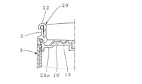
図1および図2において、1は容器体で、内外2重容器2、3から形成されている。内外容器間には間隙が形成されていて、内容器2胴部2aの上端部外面は大外径部に形成され、かつ該大外径部外側には下方へ開口する溝部4が形成されている。
Hereinafter, the present invention will be described with reference to embodiments shown in the drawings.
In FIGS. 1 and 2,
溝部4には、外容器3の胴部3a上端部が抜止め部を介して嵌合されている。内容器2胴部2aの上端部内面には係合用周壁5が螺合されており、かつ係合周壁5の上下方向中間部外面に形成された外向きフランジ6が内容器2胴部2aの上端へ係合されている。7はシールリングで、係合周壁5外面と内容器胴部2aの上端部内面との間へ嵌合されている。
The upper end portion of the body portion 3a of the
係合周壁5の上下方向中間部には頂壁10が設けられている。頂壁10の後部(図面において左右方向を前後とする。)かつ左右方向中間部には飲み口部11が形成されている。頂壁10中央部には軸孔12が形成されており、また飲み口部11と軸孔12との間には空気置換孔13が形成されている。さらに、頂壁10には、図4にも示すように後述の蓋板厚肉部26が係合可能な係合凹所26aが設けられている。係合凹所は蓋板20の開蓋状態を保持させるためのもので、したがって、本実施形態では飲み口部11から左ないし右方向へ蓋板20を90度回動させた位置に対応する位置の2箇所に設けるが、これに限定されることなく、例えば、飲み口部11に対して軸対称の位置にさらに追加的に設けてもよく、あるいはこれら3箇所の係合凹所をつないで半円弧状の溝部に形成することも可能である。
A
蓋板20は、図2に明示されているように、基端部下面に突設された回動軸21が頂壁10の軸孔12へ回動自在に嵌合されている。蓋板先端部は上方へ屈曲されて上端部がフック22に形成されており、フック22は係合周壁5上端へ係合されている。
As clearly shown in FIG. 2, the
蓋板20下面には栓蓋23が突設されており、栓蓋23は空気置換孔13へ離脱可能に嵌合されている。栓蓋23と回動軸21との間の蓋板20部分には左右方向へ伸びる薄肉ヒンジ24が形成されている。また蓋板20基端部下面には回動軸21を中心として左右対称位置に前面開口の連通用凹部25が形成されている。さらに蓋板20先端部下面には厚肉部26が形成されていて、該厚肉部26は閉蓋時に飲み口部11へ嵌合可能に形成されている。
A
蓋板20の形状には特に限定はないが、左右の幅が飲み口部11を覆うに足りる寸法で、かつ図1に示すように蓋板20基端(前端)の左右両端が頂壁10の左右方向への直径上に位置する左右対称の形状であることが好ましい。
The shape of the
次に作用について説明する。
図1および図2は飲み口部11と空気置換孔13とが閉塞された閉蓋状態を示すもので、空気置換孔13は栓蓋23が嵌合されることで閉塞され、また飲み口部11は蓋板20の先端側の厚肉部26が嵌合されることによって閉塞されている。
Next, the operation will be described.
1 and 2 show a closed state in which the
開蓋するには、フック22を係合周壁5から上方へ離脱させ、次いで図2に点線で示すように、蓋板20の先端側を薄肉ヒンジ24を介して回動させることにより栓蓋23を空気置換孔13から上方へ離脱させる。
In order to open the lid, the
次いで、蓋板20を左右いずれかの周方向(本実施形態では左方向)へ回動させる。回動角度はほぼ90度にする。この角度で蓋板20を回動させると、図3に示すように蓋板20基端(前端)の左右両端が頂壁10の前後方向への直径上に位置すると共に、連通用凹部25の一方が空気置換孔13の上方へ位置するため、容器体1内部が空気置換孔13と連通用凹部25とを介して外気と連通し、飲み口部11を介して飲料が注出される際に空気が容器体内へ導入される。なお、蓋板20を90度回動させた後、フック22を係合周壁5へ係合させる。
Next, the
飲料を飲み口部11から注出した後、フック22を係合周壁5から離脱させて上記と反対方向へ約90度回動させればよく、すると図1に示すように空気置換孔13が栓蓋23によって閉塞されると共に、飲み口部11が蓋板20の先端側によって上方から覆われる。
After the beverage is poured out from the
なお、上記では空気置換孔13は、図1において薄肉ヒンジ24より前方の頂壁10部分に設けられているが、例えば、図3において空気置換孔13が薄肉ヒンジ24とフック22との間の蓋板20部分の下方に位置するように形成すれば、連通用凹部25は必ずしも必要とされない。
In the above description, the
栓蓋23が空気置換孔13から上方へ離脱して、頂壁10上に載ることで蓋板20下面と頂壁10上面との間に間隙が生じ、この間隙を介して空気置換孔13が外気と連通可能となるからである。
When the
容器体1を洗浄するには、係合周壁5を容器体1から螺脱させればよい。
なお、本発明はタンブラー容器に適用することも可能である。
In order to clean the
The present invention can also be applied to a tumbler container.
1 容器体
2、3 内外2重容器
5 係合用周壁
10 頂壁1
11 飲み口部
13 空気置換孔
20 蓋板
23 栓蓋
24 ヒンジ
25 連通用凹部
DESCRIPTION OF
11
Claims (2)
前記容器体の開口部周縁から係合用周壁(5)を立設し、
前記容器体頂壁(10)に周方向へ回動自在に枢着した蓋板(20)にヒンジ(24)を形成して、該ヒンジを介して蓋板(20)先端側を上下方向へ回動可能に形成し、かつ蓋板(20)先端部を前記係合用周壁(5)へ着脱自在に係合させ、
前記蓋板(20)下面であって蓋板(20)先端部とヒンジ(24)との間に空気置換孔(13)へ嵌合可能な栓蓋(23)を形成すると共に、蓋板(20)下面に外部との連通用凹部(25)を設け、
前記蓋板(20)は、前記飲み口部(11)と空気置換孔(13)とを同時に閉塞する閉蓋位置と、
蓋板(20)を上方へ回動させることにより、蓋板(20)先端部を係合用周壁(5)から離脱させて蓋板(20)を周方向へ回動させ前記飲み口部(11)を開口すると共に、空気置換孔(13)から栓蓋(23)を離脱させて空気置換孔(13)を連通用凹部(25)を介して外部へ連通させる開蓋位置とを有することを特徴とする。 A drinking mouth part (11) and an air replacement hole (13) are opened in the top wall (10) which closes the opening part of the container body (1) ,
The peripheral wall for engagement (5) is erected from the peripheral edge of the opening of the container body,
A hinge (24) is formed on a lid plate (20) pivotably attached to the top wall (10) of the container body in the circumferential direction, and the tip side of the lid plate (20) is vertically moved through the hinge. It is formed so as to be rotatable, and the end of the lid plate (20 ) is detachably engaged with the engaging peripheral wall (5) ,
To form the fittable to air displacement hole (13) Senfuta (23) between said cover plate (20) the cover plate is formed on the bottom surface (20) distal end and a hinge (24), cover plate ( 20 ) A recess ( 25 ) for communication with the outside is provided on the lower surface ,
The lid plate (20) has a closed position for simultaneously closing the drinking mouth portion (11) and the air replacement hole (13) ;
By rotating the cover plate (20) upward, the tip of the cover plate (20) is detached from the peripheral wall for engagement (5), and the cover plate (20) is rotated in the circumferential direction, thereby the mouthpiece (11 ) And a lid opening position for detaching the plug lid (23 ) from the air replacement hole (13) and communicating the air replacement hole (13) to the outside through the communication recess ( 25 ). Features.
Priority Applications (1)
| Application Number | Priority Date | Filing Date | Title |
|---|---|---|---|
| JP2007340098A JP5019388B2 (en) | 2007-12-28 | 2007-12-28 | Beverage container |
Applications Claiming Priority (1)
| Application Number | Priority Date | Filing Date | Title |
|---|---|---|---|
| JP2007340098A JP5019388B2 (en) | 2007-12-28 | 2007-12-28 | Beverage container |
Publications (2)
| Publication Number | Publication Date |
|---|---|
| JP2009161201A JP2009161201A (en) | 2009-07-23 |
| JP5019388B2 true JP5019388B2 (en) | 2012-09-05 |
Family
ID=40964291
Family Applications (1)
| Application Number | Title | Priority Date | Filing Date |
|---|---|---|---|
| JP2007340098A Expired - Fee Related JP5019388B2 (en) | 2007-12-28 | 2007-12-28 | Beverage container |
Country Status (1)
| Country | Link |
|---|---|
| JP (1) | JP5019388B2 (en) |
Family Cites Families (6)
| Publication number | Priority date | Publication date | Assignee | Title |
|---|---|---|---|---|
| JPH03115142U (en) * | 1990-03-08 | 1991-11-27 | ||
| US6752287B1 (en) * | 2003-04-08 | 2004-06-22 | Shin-Shuoh Lin | Splash-proof beverage lid slide closure |
| US20050127076A1 (en) * | 2003-12-10 | 2005-06-16 | Siew Wai Vivian Foo | Container for aerated beverages |
| US20060043091A1 (en) * | 2004-08-31 | 2006-03-02 | Pinelli Steven N | Seal for reclosable cap enclosure |
| JP2007030984A (en) * | 2005-07-27 | 2007-02-08 | Ikoma Kagaku Kogyo:Kk | Lid body with tap |
| JP3136174U (en) * | 2007-08-01 | 2007-10-18 | パール金属株式会社 | Beverage container |
-
2007
- 2007-12-28 JP JP2007340098A patent/JP5019388B2/en not_active Expired - Fee Related
Also Published As
| Publication number | Publication date |
|---|---|
| JP2009161201A (en) | 2009-07-23 |
Similar Documents
| Publication | Publication Date | Title |
|---|---|---|
| US9315305B2 (en) | Canned beverage sealer | |
| US20230040658A1 (en) | Water Bottle | |
| JP4482944B2 (en) | Beverage container with lid | |
| DE602006012899D1 (en) | Closing mechanism for container openings | |
| JP2007022567A5 (en) | ||
| KR200480924Y1 (en) | Tumbler cap | |
| JP2014094044A (en) | Beverage extraction container | |
| JP3136174U (en) | Beverage container | |
| JP4470224B2 (en) | Inner cap for beverage containers | |
| JP2021191698A5 (en) | ||
| JP5019388B2 (en) | Beverage container | |
| JP2022051724A (en) | Bottle cap and one-hand operation bottle | |
| JP3178393U (en) | Beverage container closure | |
| JP3164205U (en) | Portable beverage container | |
| JP2022105258A (en) | Bottle cap and one-hand operation bottle | |
| JP4514613B2 (en) | 2-piece hinge cap | |
| JP4184048B2 (en) | Application stopper | |
| JP3228569U (en) | tumbler | |
| JP6026813B2 (en) | Beverage container | |
| JP4990444B2 (en) | Beverage container with straw | |
| US20180029757A1 (en) | One-touch cap | |
| JP5227401B2 (en) | One-piece attachment cap that can be opened with one push | |
| JP3177234U (en) | Beverage container closure | |
| JP4926569B2 (en) | Spout | |
| JP3190328U (en) | Tablet container lid |
Legal Events
| Date | Code | Title | Description |
|---|---|---|---|
| A621 | Written request for application examination |
Free format text: JAPANESE INTERMEDIATE CODE: A621 Effective date: 20100625 |
|
| A977 | Report on retrieval |
Free format text: JAPANESE INTERMEDIATE CODE: A971007 Effective date: 20120227 |
|
| A131 | Notification of reasons for refusal |
Free format text: JAPANESE INTERMEDIATE CODE: A131 Effective date: 20120307 |
|
| A521 | Request for written amendment filed |
Free format text: JAPANESE INTERMEDIATE CODE: A523 Effective date: 20120418 |
|
| TRDD | Decision of grant or rejection written | ||
| A01 | Written decision to grant a patent or to grant a registration (utility model) |
Free format text: JAPANESE INTERMEDIATE CODE: A01 Effective date: 20120606 |
|
| A01 | Written decision to grant a patent or to grant a registration (utility model) |
Free format text: JAPANESE INTERMEDIATE CODE: A01 |
|
| A61 | First payment of annual fees (during grant procedure) |
Free format text: JAPANESE INTERMEDIATE CODE: A61 Effective date: 20120606 |
|
| R150 | Certificate of patent or registration of utility model |
Ref document number: 5019388 Country of ref document: JP Free format text: JAPANESE INTERMEDIATE CODE: R150 Free format text: JAPANESE INTERMEDIATE CODE: R150 |
|
| FPAY | Renewal fee payment (event date is renewal date of database) |
Free format text: PAYMENT UNTIL: 20150622 Year of fee payment: 3 |
|
| LAPS | Cancellation because of no payment of annual fees |