JP5017993B2 - Circulation type crushing mechanism and toilet equipment - Google Patents
Circulation type crushing mechanism and toilet equipment Download PDFInfo
- Publication number
- JP5017993B2 JP5017993B2 JP2006269194A JP2006269194A JP5017993B2 JP 5017993 B2 JP5017993 B2 JP 5017993B2 JP 2006269194 A JP2006269194 A JP 2006269194A JP 2006269194 A JP2006269194 A JP 2006269194A JP 5017993 B2 JP5017993 B2 JP 5017993B2
- Authority
- JP
- Japan
- Prior art keywords
- crushing
- crushing mechanism
- rotary
- unit
- inner cylinder
- Prior art date
- Legal status (The legal status is an assumption and is not a legal conclusion. Google has not performed a legal analysis and makes no representation as to the accuracy of the status listed.)
- Expired - Fee Related
Links
- 230000007246 mechanism Effects 0.000 title claims description 135
- 239000000463 material Substances 0.000 claims description 60
- 238000000034 method Methods 0.000 claims description 51
- 230000008569 process Effects 0.000 claims description 48
- 230000001737 promoting effect Effects 0.000 claims description 33
- 230000002093 peripheral effect Effects 0.000 claims description 15
- 239000010865 sewage Substances 0.000 claims description 9
- 238000012545 processing Methods 0.000 claims description 8
- 238000005086 pumping Methods 0.000 claims description 6
- 239000002699 waste material Substances 0.000 claims description 5
- XLYOFNOQVPJJNP-UHFFFAOYSA-N water Substances O XLYOFNOQVPJJNP-UHFFFAOYSA-N 0.000 description 65
- 238000010586 diagram Methods 0.000 description 24
- 230000000694 effects Effects 0.000 description 12
- 238000003780 insertion Methods 0.000 description 9
- 230000037431 insertion Effects 0.000 description 9
- 230000009471 action Effects 0.000 description 6
- 230000013872 defecation Effects 0.000 description 6
- 238000002347 injection Methods 0.000 description 6
- 239000007924 injection Substances 0.000 description 6
- 239000007787 solid Substances 0.000 description 6
- 239000008399 tap water Substances 0.000 description 5
- 235000020679 tap water Nutrition 0.000 description 5
- 238000005406 washing Methods 0.000 description 5
- 238000004140 cleaning Methods 0.000 description 4
- 238000003756 stirring Methods 0.000 description 4
- 235000013311 vegetables Nutrition 0.000 description 4
- 235000013305 food Nutrition 0.000 description 3
- 230000009467 reduction Effects 0.000 description 3
- 239000011347 resin Substances 0.000 description 3
- 229920005989 resin Polymers 0.000 description 3
- 238000004904 shortening Methods 0.000 description 3
- 230000001133 acceleration Effects 0.000 description 2
- 239000002609 medium Substances 0.000 description 2
- 239000000203 mixture Substances 0.000 description 2
- 238000012544 monitoring process Methods 0.000 description 2
- 238000005192 partition Methods 0.000 description 2
- 230000002195 synergetic effect Effects 0.000 description 2
- 241000251468 Actinopterygii Species 0.000 description 1
- 210000000988 bone and bone Anatomy 0.000 description 1
- 239000000919 ceramic Substances 0.000 description 1
- 230000003111 delayed effect Effects 0.000 description 1
- 238000007599 discharging Methods 0.000 description 1
- 239000006185 dispersion Substances 0.000 description 1
- 239000012526 feed medium Substances 0.000 description 1
- 238000009434 installation Methods 0.000 description 1
- JEIPFZHSYJVQDO-UHFFFAOYSA-N iron(III) oxide Inorganic materials O=[Fe]O[Fe]=O JEIPFZHSYJVQDO-UHFFFAOYSA-N 0.000 description 1
- 239000007788 liquid Substances 0.000 description 1
- 239000002184 metal Substances 0.000 description 1
- 238000012986 modification Methods 0.000 description 1
- 230000004048 modification Effects 0.000 description 1
- 239000002245 particle Substances 0.000 description 1
- 239000013618 particulate matter Substances 0.000 description 1
- 230000000149 penetrating effect Effects 0.000 description 1
- 238000010298 pulverizing process Methods 0.000 description 1
- 239000007779 soft material Substances 0.000 description 1
- 239000002904 solvent Substances 0.000 description 1
- 239000000126 substance Substances 0.000 description 1
- 239000000725 suspension Substances 0.000 description 1
- 230000009897 systematic effect Effects 0.000 description 1
- 238000011144 upstream manufacturing Methods 0.000 description 1
Images


Classifications
-
- E—FIXED CONSTRUCTIONS
- E03—WATER SUPPLY; SEWERAGE
- E03D—WATER-CLOSETS OR URINALS WITH FLUSHING DEVICES; FLUSHING VALVES THEREFOR
- E03D11/00—Other component parts of water-closets, e.g. noise-reducing means in the flushing system, flushing pipes mounted in the bowl, seals for the bowl outlet, devices preventing overflow of the bowl contents; devices forming a water seal in the bowl after flushing, devices eliminating obstructions in the bowl outlet or preventing backflow of water and excrements from the waterpipe
- E03D11/02—Water-closet bowls ; Bowls with a double odour seal optionally with provisions for a good siphonic action; siphons as part of the bowl
- E03D11/11—Bowls combined with a reservoir, e.g. containing apparatus for disinfecting or for disintegrating
-
- B—PERFORMING OPERATIONS; TRANSPORTING
- B02—CRUSHING, PULVERISING, OR DISINTEGRATING; PREPARATORY TREATMENT OF GRAIN FOR MILLING
- B02C—CRUSHING, PULVERISING, OR DISINTEGRATING IN GENERAL; MILLING GRAIN
- B02C18/00—Disintegrating by knives or other cutting or tearing members which chop material into fragments
- B02C18/0084—Disintegrating by knives or other cutting or tearing members which chop material into fragments specially adapted for disintegrating garbage, waste or sewage
- B02C18/0092—Disintegrating by knives or other cutting or tearing members which chop material into fragments specially adapted for disintegrating garbage, waste or sewage for waste water or for garbage
-
- B—PERFORMING OPERATIONS; TRANSPORTING
- B02—CRUSHING, PULVERISING, OR DISINTEGRATING; PREPARATORY TREATMENT OF GRAIN FOR MILLING
- B02C—CRUSHING, PULVERISING, OR DISINTEGRATING IN GENERAL; MILLING GRAIN
- B02C18/00—Disintegrating by knives or other cutting or tearing members which chop material into fragments
- B02C18/06—Disintegrating by knives or other cutting or tearing members which chop material into fragments with rotating knives
- B02C18/08—Disintegrating by knives or other cutting or tearing members which chop material into fragments with rotating knives within vertical containers
- B02C18/12—Disintegrating by knives or other cutting or tearing members which chop material into fragments with rotating knives within vertical containers with drive arranged below container
-
- B—PERFORMING OPERATIONS; TRANSPORTING
- B02—CRUSHING, PULVERISING, OR DISINTEGRATING; PREPARATORY TREATMENT OF GRAIN FOR MILLING
- B02C—CRUSHING, PULVERISING, OR DISINTEGRATING IN GENERAL; MILLING GRAIN
- B02C18/00—Disintegrating by knives or other cutting or tearing members which chop material into fragments
- B02C18/06—Disintegrating by knives or other cutting or tearing members which chop material into fragments with rotating knives
- B02C18/16—Details
- B02C18/18—Knives; Mountings thereof
-
- B—PERFORMING OPERATIONS; TRANSPORTING
- B02—CRUSHING, PULVERISING, OR DISINTEGRATING; PREPARATORY TREATMENT OF GRAIN FOR MILLING
- B02C—CRUSHING, PULVERISING, OR DISINTEGRATING IN GENERAL; MILLING GRAIN
- B02C23/00—Auxiliary methods or auxiliary devices or accessories specially adapted for crushing or disintegrating not provided for in preceding groups or not specially adapted to apparatus covered by a single preceding group
- B02C23/08—Separating or sorting of material, associated with crushing or disintegrating
- B02C23/16—Separating or sorting of material, associated with crushing or disintegrating with separator defining termination of crushing or disintegrating zone, e.g. screen denying egress of oversize material
- B02C2023/165—Screen denying egress of oversize material
Landscapes
- Engineering & Computer Science (AREA)
- Food Science & Technology (AREA)
- Environmental & Geological Engineering (AREA)
- Health & Medical Sciences (AREA)
- Life Sciences & Earth Sciences (AREA)
- Hydrology & Water Resources (AREA)
- Public Health (AREA)
- Water Supply & Treatment (AREA)
- Crushing And Pulverization Processes (AREA)
- Bidet-Like Cleaning Device And Other Flush Toilet Accessories (AREA)
- Treatment Of Sludge (AREA)
Description
この発明は循環型破砕機構およびこの循環型破砕機構を使用したトイレ装置に関する。詳しくは、破砕物を含んだ破砕水を循環させながら、破砕刃を備えた破砕機構によって破砕処理することで、破砕物の破砕処理時間を短縮すると共に、節水効果及び機構や装置の小型化を狙ったものである。 The present invention relates to a circulation type crushing mechanism and a toilet apparatus using the circulation type crushing mechanism. Specifically, while crushing crushed water containing crushed material, crushing is performed by a crushing mechanism equipped with a crushing blade, thereby shortening the crushing time of the crushed material and reducing the water-saving effect and the size of the mechanism and device. It is the target.
比較的柔らかく水分を含んだ固形物などを破砕したり、液体と混合させたりするには、通常攪拌処理による場合が多い(例えば、特許文献1〜3)。これに対して繊維質で比較的硬い固形物などを破砕するには、破砕刃などを使用した破砕処理による場合が多い(例えば特許文献4)。 In order to crush a relatively soft solid substance containing moisture or to mix it with a liquid, there are many cases in which a normal stirring process is usually used (for example, Patent Documents 1 to 3). On the other hand, in order to crush fibrous and relatively hard solids, there are many cases of crushing using a crushing blade or the like (for example, Patent Document 4).
特許文献1では、攪拌翼を使用し、攪拌作用のみで汚物を粒状化している。特許文献2では、特許文献1と同じく攪拌装置を使用することで比較的軟質な汚物などを攪拌処理している。特許文献3では、攪拌装置を使用して、固体粒子の懸濁液をコロイド状にする分散装置であって、他の溶剤などと均質に混合させることができるようにしたものである。 In patent document 1, the stirring blade is used and the filth is granulated only by stirring action. In Patent Document 2, as in Patent Document 1, a stirrer is used to stir relatively soft filth and the like. In Patent Document 3, a dispersion device that uses a stirrer to make a suspension of solid particles into a colloidal shape, which can be homogeneously mixed with another solvent or the like.
一方、特許文献4では、破砕刃を使用することで、野菜、魚の骨、雑飯類を破砕して、下水管に排出している。 On the other hand, in patent document 4, the crushing blade is used, and vegetables, fish bones, and miscellaneous foods are crushed and discharged to the sewer pipe.
ところで、特許文献1〜3に示される技術では、野菜などの比較的硬めの固形物に対しては充分な破砕効果は期待できない。十分破砕するためには破砕処理時間がかかるし、破砕処理中は破砕水を補給しなければならないので、破砕水の使用量も膨大になる。 By the way, with the technique shown by patent documents 1-3, sufficient crushing effect cannot be expected with respect to comparatively hard solids, such as vegetables. It takes a long time for the crushing process to sufficiently crush, and the crushing water must be replenished during the crushing process.
また、特許文献4に開示された技術にあっては、特許文献1〜3よりも破砕効果は大きいが、ハンマーミル方式と呼称される回転刃と固定刃とからなる破砕機構によって破砕した破砕物を、循環路を経て、破砕機構の上流側へ戻すことにより、破砕物を繰り返し破砕する構成となっている。このため、破砕機構を収容する粉砕室とは独立した経路として循環路を設けられているので、粉砕室と循環路を組み合わせた構成となり、装置が大型化してしまう問題がある。 Moreover, in the technique disclosed in Patent Document 4, the crushing effect is larger than those in Patent Documents 1 to 3, but the crushed material is crushed by a crushing mechanism consisting of a rotary blade and a fixed blade called a hammer mill method. Is returned to the upstream side of the crushing mechanism through the circulation path, so that the crushed material is repeatedly crushed. For this reason, since the circulation path is provided as a path independent of the crushing chamber that accommodates the crushing mechanism, the crushing chamber and the circulation path are combined, and there is a problem that the apparatus becomes large.
そこで、この発明はこのような従来の課題を解決したものであって、特に破砕処理時間の短縮と節水を実現しつつ、機構や装置の小型化を実現した循環型破砕機構およびこれを使用したトイレ装置を提案するものである。 Therefore, the present invention solves such a conventional problem, and in particular, uses a circulation type crushing mechanism that realizes a reduction in the size of the mechanism and the apparatus while realizing reduction of crushing time and water saving, and the same. A toilet device is proposed.
上述の課題を解決するため、請求項1に記載したこの発明に係る循環型破砕機構は、破砕物の投入口と該破砕物の排出口とを有する筒状本体と、
上記筒状本体の内部に、所定の間隙を保持して取り付けられた内筒と、
上記内筒の内側に設けられた破砕機構とからなり、
上記破砕機構は、回転破砕部と、該回転破砕部と対向するように設けられた固定破砕部と、上記回転破砕部の駆動部とで構成され、
上記内筒と上記筒状本体との間に循環流を形成しながら、上記破砕物を破砕するようにしたことを特徴とする
また、請求項13に記載したこの発明に係るトイレ装置は、便器本体と、
上記便器本体の下面側の開口部に取り付けられた循環型破砕機構とで構成され、上記循環型破砕機構は、
上記開口部と対向する位置に設けられた汚物の投入口と、該汚物の排出口とを有する筒状本体と、
上記投入口と対峙すると共に、上記筒状本体の内部に所定の間隙を保持して取り付けられた内筒と、
上記内筒の内側に設けられた破砕機構とからなり、
上記破砕機構は、回転破砕部と、該回転破砕部と対向するように設けられた固定破砕部と、上記回転破砕部の駆動部とで構成され、
上記内筒と上記筒状本体との間に循環流を形成しながら上記汚物を破砕して、上記排出口より排出するようにしたことを特徴とする。
In order to solve the above-described problem, a circulating crushing mechanism according to the present invention described in claim 1 includes a cylindrical main body having a crushed material input port and a crushed material discharge port,
An inner cylinder attached with a predetermined gap inside the cylindrical main body; and
It consists of a crushing mechanism provided inside the inner cylinder,
The crushing mechanism includes a rotary crushing unit, a fixed crushing unit provided to face the rotary crushing unit, and a drive unit of the rotary crushing unit.
The crushed material is crushed while forming a circulation flow between the inner cylinder and the cylindrical main body. The toilet apparatus according to the invention described in claim 13 is a toilet bowl. The body,
It is composed of a circulation type crushing mechanism attached to the opening on the lower surface side of the toilet body,
A cylindrical body having a waste inlet provided at a position facing the opening, and a waste outlet;
An inner cylinder facing the input port and attached with a predetermined gap inside the cylindrical main body,
It consists of a crushing mechanism provided inside the inner cylinder,
The crushing mechanism includes a rotary crushing unit, a fixed crushing unit provided to face the rotary crushing unit, and a drive unit of the rotary crushing unit.
The filth is crushed while forming a circulation flow between the inner cylinder and the cylindrical main body, and is discharged from the discharge port.
この発明の循環型破砕機構では、筒状本体内に内筒を備え、内筒の内部に破砕機構を配する。破砕機構は回転破砕部と固定破砕部とで構成され、回転破砕部は回転破砕刃が使用される。固定破砕部は多数の開孔部が形成された円盤や、周面に開孔部又は切れ込み部が形成された内筒自身を用いる。多数の開孔部が形成された円盤と、周面に開孔部又は切れ込み部が形成された内筒のそれぞれを同時に固定破砕部として使用すれば、破砕効果が大きい。 In the circulation type crushing mechanism of the present invention, an inner cylinder is provided in the cylindrical main body, and the crushing mechanism is arranged inside the inner cylinder. The crushing mechanism is composed of a rotary crushing part and a fixed crushing part, and the rotary crushing part uses a rotary crushing blade. The fixed crushing part uses a disk in which a large number of apertures are formed, or an inner cylinder itself in which apertures or cuts are formed on the peripheral surface. If each of the disk in which a large number of apertures are formed and the inner cylinder in which the apertures or notches are formed on the peripheral surface are used simultaneously as fixed crushing units, the crushing effect is great.
筒状本体と内筒との間は所定の間隙ができるように離間して取り付けられる。また破砕機構と協働する循環流促進部が設けられる。循環流促進部は、内筒の上部と下部との間を破砕物を含めた破砕水が循環するときの促進機能を果たす。循環流促進部は、回転破砕刃の回転軸に取り付ける場合と、上述した間隙内に取り付ける場合とが考えられる。その双方を設けると一層効果的である。 The cylindrical main body and the inner cylinder are attached so as to be separated so as to form a predetermined gap. In addition, a circulation flow promoting unit that cooperates with the crushing mechanism is provided. A circulation flow promotion part fulfill | performs the promotion function when crushed water including a crushed material circulates between the upper part and lower part of an inner cylinder. A case where the circulating flow promoting portion is attached to the rotary shaft of the rotary crushing blade and a case where the circulating flow promoting portion is attached within the gap described above are considered. It is more effective to provide both of them.
間隙内に取り付けるときは、その周方向を分断するように1枚以上の板体が、循環流の促進板として機能するように取り付けられる。 When installed in the gap, one or more plates are attached so as to function as a circulation flow promoting plate so as to divide the circumferential direction.
回転破砕部を回転させることで、破砕物を含めた破砕水は筒状本体の内部で渦流となる。その一方、筒状本体と内筒との間の間隙では、筒状本体の内面に取り付けられた循環流促進板によって渦流が阻害されるため渦流は循環流となり、破砕機構を通過する循環流が生まれる。 By rotating the rotary crushing part, the crushed water including the crushed material becomes a vortex inside the cylindrical main body. On the other hand, in the gap between the cylindrical main body and the inner cylinder, the vortex flow is inhibited by the circulation flow promoting plate attached to the inner surface of the cylindrical main body. to be born.
その結果、内筒内に投下された破砕物は、固定破砕刃と回転破砕部との間で破砕処理がなされ、破砕処理されて内筒の下部や内筒の側面側に押し出された破砕物は、さらにこの間隙を上昇して再び内筒の上部側に落ち込むような循環流が発生する。 As a result, the crushed material dropped in the inner cylinder is crushed between the fixed crushing blade and the rotary crushing section, and crushed and extruded to the lower part of the inner cylinder and the side of the inner cylinder. Then, a circulating flow is generated in which the gap further rises and falls to the upper side of the inner cylinder again.
この循環流が発生すると破砕物は幾度となく破砕機構を通過することになるから、それだけ破砕処理が進行して、細かく粒状化することができる。結果として破砕処理時間を短縮できる。 When this circulating flow is generated, the crushed material will pass through the crushing mechanism several times, so that the crushing process proceeds so that it can be finely granulated. As a result, the crushing time can be shortened.
破砕処理の間は、筒状本体内は閉塞されるため、破砕水は破砕処理前に給水されるだけである。そのため、節水効果が期待できる。 During the crushing process, the inside of the cylindrical body is closed, so that the crushing water is only supplied before the crushing process. Therefore, water saving effect can be expected.
また、循環流が生成される経路は、筒状本体の内部で完結している。このため、筒状本体とは異なる循環流の経路が不要であって、機構の小型化、簡素化を図ることができる。 Moreover, the path | route through which a circulating flow is produced | generated is completed inside the cylindrical main body. For this reason, a circulation flow path different from that of the cylindrical main body is unnecessary, and the mechanism can be reduced in size and simplified.
このような循環型破砕機構はトイレ装置に適用できる。トイレ装置は固定式のトイレ装置でも可搬式のトイレ装置(いわゆる簡易トイレ装置)の何れにも適用できる。簡易トイレ装置に適用する場合には、筒状本体に圧送手段を装備すると好適である。圧送媒体としては水や空気が好ましい。とりわけ、圧送媒体として空気を使用した場合には、圧送手段としてはエアーコンプレッサや圧縮空気貯留タンクが好適であって、破砕し、粒状化した破砕物を、空気圧を利用して下水管若しくは固定トイレ装置内に一気に圧送して排出する。 Such a circulation type crushing mechanism can be applied to a toilet apparatus. The toilet device can be applied to either a fixed toilet device or a portable toilet device (so-called simple toilet device). When applied to a simple toilet device, it is preferable that the cylindrical main body is equipped with a pressure feeding means. Water or air is preferable as the pressure feeding medium. In particular, when air is used as the pressure-feeding medium, an air compressor or a compressed air storage tank is suitable as the pressure-feeding means, and the crushed and granulated crushed material is sewage pipes or fixed toilets using air pressure. It is discharged by pumping into the device at once.
トイレ装置にこの循環型破砕機構を適用すると、汚物は比較的軟質な破砕物であるため、破砕処理時間も短く、節水効果も期待でき、さらに破砕物は粒状化しているので細管を使用して下水管まで、詰まりなく導くことができる。 When this circulation type crushing mechanism is applied to a toilet device, the filth is a relatively soft crushed material, so the crushing time is short and the water-saving effect can be expected, and the crushed material is granulated. It can guide to the sewer pipe without clogging.
この発明に係る循環型破砕機構は、内筒の中に破砕機構を配し、内筒と筒状本体との間に循環流を起こして幾度となく破砕機構を通過するようにしたものである。 The circulation type crushing mechanism according to the present invention is such that a crushing mechanism is arranged in an inner cylinder, and a circulating flow is caused between the inner cylinder and the cylindrical main body so as to pass through the crushing mechanism several times. .
これによれば、破砕物が比較的硬い固形物であったとしても充分な破砕処理効果を期待できる、破砕処理循環も短縮され、また節水効果も得られる。さらに、機構の小型化、簡素化も図ることができる。 According to this, even if the crushed material is a relatively hard solid, a sufficient crushing effect can be expected, the crushing circulation can be shortened, and a water saving effect can be obtained. Further, the mechanism can be reduced in size and simplified.
また、この発明に係るトイレ装置では、破砕機構を配した循環型破砕機構を用いて汚物を破砕処理するようにしたものである。 Moreover, in the toilet apparatus which concerns on this invention, a waste material is crushed using the circulation type crushing mechanism which arranged the crushing mechanism.
これによれば破砕機構を用いて汚物を破砕処理するため、比較的短時間に汚物を粒状化できるので、処理時間を短縮できる。破砕処理中は給水されないため節水効果が得られる。汚物は粒状化されるため、特に簡易トイレ装置の場合にあっては、管径の細い排水管を使用しても汚物の詰まりや滞留が起こることがない。 According to this, since the filth is crushed using the crushing mechanism, the filth can be granulated in a relatively short time, so that the processing time can be shortened. Water is saved during the crushing process because water is not supplied. Since filth is granulated, clogging and stagnation of filth do not occur even when a drain pipe with a thin pipe diameter is used, particularly in the case of a simple toilet device.
また、循環破砕機構の小型化、簡素化が図られているため、トイレ装置への機構の搭載が容易である。 Moreover, since the circulation crushing mechanism is reduced in size and simplified, the mechanism can be easily mounted on the toilet device.
続いて、この発明に係る循環型破砕機構およびトイレ装置の好ましい実施例を図面を参照して詳細に説明する。 Subsequently, preferred embodiments of the circulation type crushing mechanism and the toilet apparatus according to the present invention will be described in detail with reference to the drawings.
(循環型破砕機構の説明)
図1〜図16はこの発明に係る循環型破砕機構10の概念構成を示す概念図である。図1から説明する。
(Description of circulation type crushing mechanism)
FIGS. 1-16 is a conceptual diagram which shows the conceptual structure of the circulation
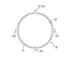
(概念説明その1)
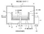
図1は第1の概念説明図である。この循環型破砕機構10は、図1に示すように破砕物の投入口とその排出口とを有する筒状本体20と、この筒状本体20の内部に、所定の間隙を保持して取り付けられた内筒30と、この内筒30の内側に設けられた破砕機構40とで構成される。
(Conceptual explanation 1)
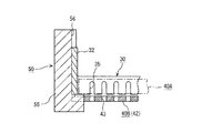
FIG. 1 is a first conceptual explanatory diagram. As shown in FIG. 1, the circulation
筒状本体20は、この例では所定の長さと内径を有する円筒体が使用され、その頭部のほぼ中央部には破砕物の投入口21が穿設され、その底部22の隅には排出口23が設けられている。
In this example, a cylindrical body having a predetermined length and an inner diameter is used as the cylindrical
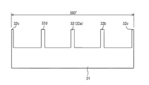
筒状本体20の内部には、筒状本体20の内周面より所定の間隙59を保持して内筒30が設置される。内筒30も所定の長さと内径を有する円筒体が使用され、図2に示すように内筒本体31と、この内筒本体31より外側と上側にそれぞれ所定長だけ突出した棒状をなす複数本の係合片(ガイド片)32とで構成される。
Inside the cylindrical
内筒本体31の長さと内径は後述する破砕機構40のサイズによって決まる。係合片32は、後述する具体例の中で説明するように、内筒30を筒状本体20に固定するために使用されるもので、ほぼ90°の角間隔を保持して4本の係合片32が内筒本体31と一体成型されたものである。
The length and inner diameter of the inner cylinder
内筒30の内部に配置される破砕機構40は、回転破砕部40Aと、この回転破砕部40Aと対向するように設けられた固定破砕部40Bと、回転破砕部40Aの駆動部40Cとで構成される。駆動部40Cは駆動モータ90が使用される。
The crushing
破砕機構40では、回転破砕部40Aを回転駆動することで、固定破砕部40Bを通過するとき、投入された破砕物が破砕されると共に、内筒30と筒状本体20との間の間隙59を経路とする循環流を形成しながら、破砕物をこの破砕機構40を幾度となく通過させることで、短時間に破砕物を粒状化する。
In the crushing
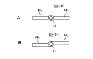
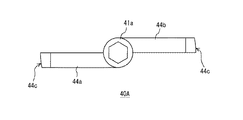
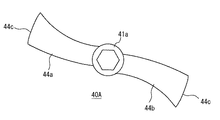
そのため、回転破砕部40Aは破砕刃が使用される。この例では図3に示すように、帯状をなす短冊状の1本の回転破砕刃44(44a,44b)が使用される。回転破砕刃44は図3Aのように回転軸41に対して同一軸心を通って左右にその腕44が延びるような形状の破砕刃か、図3Bのような軸心をそれぞれ外してその腕が左右に延びる形状をなす破砕刃の何れでも使用できる。後述する具体例では後者の構成のものが使用されている。
Therefore, a crushing blade is used for the rotary crushing
回転破砕部40Aと対向するように固定破砕部40Bが設けられる。固定破砕部40Bは回転破砕部40Aの長辺と対向するように設けて破砕部を構成することもできれば、回転破砕部40Aの短辺、つまり左右端面と対向するように設けることで破砕部を構成することもできる。
A fixed crushing
前者の例を図4に示す。この例では固定破砕部40Bとして円盤42が使用され、円盤42の厚み方向を貫くように複数の開孔部としてのスリット43が形成される。スリット43の方向は一定でもよいが、図4の例では回転破砕部40Aの回転方向と同じ方向と、別な方向との2種類の方向を持たせた構造となっている。したがって、スリット43の幅および間隔は一定であるが、その長さはスリット43の盤面位置によって相違する。固定破砕部40Bは係合手段(図示はしない)を用いて内筒30に固定される。
An example of the former is shown in FIG. In this example, a
図4に示したスリット43は、開孔部の一例であって、スリットに代えて丸孔や角孔、楕円孔としてもよく、これらの種々の孔を組み合わせて用いてもよい。
The
固定破砕部40Bは、回転破砕部40Aの上面側に対向配置することもできれば、下面側に対向配置することもできる。図1の例は下面側に配置した例であって、その場合には回転破砕部40Aの端面と円盤42の上面とが接触するか、少許の間隙を保持して対向するように配置される。固定破砕部40Bの上面を回転破砕部40Aが回転することで、両者の協働によって破砕物が破砕される。
The fixed crushing
内筒30および破砕機構40は筒状本体20の底部22より若干離隔させて、所定の間隔を隔てた状態で筒状本体20内に配置される。
The
このように構成された循環型破砕機構10の破砕処理例を図5を参照して説明する。
A crushing process example of the
筒状本体20内には少なくとも破砕機構40の一部が水没する水位まで水道水(破砕水)が満たされているものとする。この破砕水の中に破砕物が投入される。破砕物は食物や野菜などの比較的硬めの固形物や、排泄物や汚物などの比較的軟質物などであり、これらの破砕物が破砕の対象となる。
It is assumed that the cylindrical
破砕水の中に破砕物を投入した状態で、投入口21を蓋(開閉機構)60で閉じてから回転破砕部40Aを回転駆動する。回転破砕部40Aが回転すると回転破砕部40Aと固定破砕部40Bとによって破砕が行われる。破砕された破砕物はスリット43を経て固定破砕部40Bの下面側へ送られる。
In a state where crushed material is thrown into crushed water, the
ここで、回転破砕部40Aが回転すると破砕水が渦巻いて渦流となる。このとき、破砕機構40の下面側には、スリット43を経た破砕水が、順次押し出されてくる。このため筒状本体20の底部22寄りの破砕水も順次押し上げられ、そして間隙59を経て上面に向かう流れが形成される。結果として渦流は次第に対流をも生じさせて破砕機構40の上面と下面との間を循環する。すなわち循環流が発生する。この循環流によって破砕物は破砕機構40を幾度となく通過することになるから、破砕物は次第に細かく砕かれて粒状化する。循環流が発生することによって破砕物が粒状化するまでの時間が短縮されるため、破砕処理時間が短くなる。
Here, when the
循環流を効果的に発生させるためにさらに循環流促進部50が用意されている。この循環流促進部50は、回転羽根50Aを回転軸41に取り付けて使用する場合と、筒状本体20の内面に促進板50Bを取り付けて使用する場合が考えられる。何れの場合も、循環流促進部50は、破砕機構40との協働で好適な循環流促進作用を発揮する。図5の例は回転羽根50Aと促進板50Bの双方を取り付けた場合を示す。一例として促進板50Bは4枚、90°間隔で渦流を阻害するように取り付けられる。
In order to generate a circulating flow effectively, a circulating
このような循環流促進部50を設けることで、第1に回転羽根50Aによって破砕物を含んだ破砕水が固定破砕部40Bの側から筒状本体20の底部22側に強く引き込まれるとともに、引き込んだ破砕水を筒状本体20の外方側へ送る作用が生じ、破砕水が間隙59を通る上昇流となって上方に押し上げられるので、循環流が促進される。
By providing such a circulation
第2に、回転破砕部40Aを回転させることで発生する渦流が促進板50Bによって阻害されて、破砕水の渦流としての流れの勢いが上昇流に転化させられるため、循環流の増進および促進が加えられる。
Secondly, the vortex generated by rotating the rotary crushing
これらの循環流促進作用によって、破砕物の破砕機構40を通過する頻度が増し、破砕機構40による破砕頻度が高くなり、破砕物は短時間に細かく裁断されて粒状化される。破砕処理を所定時間行い、十分粒状化した段階になると、排出口23側の閉止弁部材としての閉塞蓋25を開けて、排出処理を行う。排出口23は下水管などにつながれているので、粒状物を全て下水管側に排出できる。
These circulating flow promoting actions increase the frequency of the crushed material passing through the crushing
(概念説明その2)
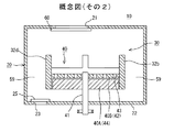
図6は、第2の概念説明図である。図6に示す循環型破砕機構10と図1に示した循環型破砕機構10との異なる点は、破砕機構40にあって回転破砕部40Aの上面側に固定破砕部40Bを設けた点である。その他は図1の構成と同一であるので、説明は割愛する。
(Conceptual explanation 2)
FIG. 6 is a second conceptual explanatory diagram. The difference between the circulating crushing
図6のように固定破砕部40Bを回転破砕部40Aの上面であって、この回転破砕部40Aと接触するか、僅かな間隙を保持して固定破砕部40Bが取り付けられる。回転破砕部40Aは図1に示した短冊状の回転破砕刃44が使用され、固定破砕部40Bも図1に示した円盤42が使用され、図4に示すように多数のスリット43が設けられた円盤42が使用されることは図1の場合と同じである。
As shown in FIG. 6, the fixed crushing
固定破砕部40Bを回転破砕部40Aの上面に配置した場合でも、固定破砕部40Bに落下した破砕物が回転破砕部40Aを回転させることで回転破砕部40Aの側へ引き込まれて、破砕処理されると共に、前述の循環流によって破砕物は繰り返し破砕されて次第に破砕および裁断が進行して粒状化される。
Even when the fixed crushing
(概念説明その3)
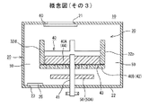
図7は図1の構成に加えて、循環流促進部50を設けた例である。循環流促進部50としてこの例では回転羽根50Aが使用され、これが固定破砕部40Bの下側であって、固定破砕部40Bと所定の間隔を保持して回転破砕部40Aの回転軸41に取り付け固定される。
(Conceptual explanation 3)
FIG. 7 is an example in which a circulation
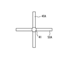
回転羽根50Aは図8に示すように左右に延びる1枚羽根であって、この例では薄い板体(帯状体)が使用され、これが回転破砕部40Aに対してほぼ直交するように固定される。もちろん回転破砕部40Aと平行となるように固定することもできる。
As shown in FIG. 8, the
回転羽根50Aを取り付けると、回転破砕部40Aが回転することによって、破砕機構40の下流側が攪拌され、攪拌された破砕水は筒状本体20の底部22から筒状本体20の内面に沿って間隙59を通って上昇する。この上昇流によって破砕機構40を跨ぐ循環流が発生し、破砕機構40を通過する循環流が生ずる。この循環流によって破砕物の破砕処理が促進される。
When the
(概念説明その4)
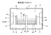
図9は、図7の他の例である。循環流促進部50を、筒状本体20の内面に取り付けた場合を示す。この場合には回転羽根50Aに代えて促進板50Bが使用される。促進板50Bは、ほぼ90°の間隔でその板面が筒状本体20の内面と直交するように固定される。促進板50Bの長さや幅は任意であるが、この例では内筒30と対向する位置に、内筒30の長さよりも長く選定された板体が使用される。促進板50Bの幅は内筒30に届くか、それよりも若干短めの板体が使用される。図9の例は短めの板体を使用した場合である。促進板50Bを内筒30などの取り付け板としても使用する場合は内筒30に届くような幅の板体が使用される。
(Conceptual explanation 4)
FIG. 9 is another example of FIG. The case where the circulation
筒状本体20の内面に促進板50Bを取り付けると、回転破砕部40Aの回転に伴う渦流の回転が阻害されて、渦流としての流れの勢いが間隙59を通る上昇流の勢いへと転化されるから、この上昇流が破砕機構40を跨ぐ循環流となり、図7の場合と同じようにこの循環流によって破砕物の破砕処理が促進される。
When the accelerating
(概念説明その5)
図10の例は、循環流促進部50として回転羽根50Aと促進板50Bの双方を使用した場合であり、これは動作説明で使用した図5の構成例と同一である。循環流促進部50によって図7や図9の場合よりも循環流がさらに促進され、破砕処理時間の短縮を期待できる。
(Conceptual explanation 5)
The example of FIG. 10 is a case where both the
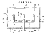
(概念説明その6)
図10までの概念説明では、固定破砕部40Bとしてスリットが設けられた円盤42を使用した例である。図11以下は円盤42に代えて内筒30自体を固定破砕部40Bとしても使用できるようにした例である。つまり、棒状をなす回転破砕部40Aの左右端面44cと対向する位置に固定破砕部40Bが設けられている例であり、この左右端面44cを破砕刃として使用した例である。
(Conceptual explanation 6)
The conceptual description up to FIG. 10 is an example in which a
そのため、図11に示すように内筒30の周面33に、下端側が解放された多数の切れ込み部としての櫛歯状のスリット35が形成されて固定破砕部40Bとなされる。つまり、この例では内筒30の一部を固定破砕部40Bとしても使用した例である。そして、回転破砕部40Aが内筒30の内周面と接触するか、僅かに離隔して対向するように回転破砕部40Aと固定破砕部40Bとの関係が選定されているものとする。
For this reason, as shown in FIG. 11, a plurality of comb-
なお、スリット35は、略櫛歯状に限らず、丸孔や長孔、楕円孔、角孔などの開孔部であってもよい。要は、回転破砕部40Aの左右端面44cと対向する位置に回転破砕部40Aとの協働で破砕物を通過させ得るよう設けられていればよい。
The
図12の例は、スリット35が多数、一定の間隔で、しかも軸線方向と同じ方向に延在するように形成されている。この他にスリットの形成間隔を変えたり、スリットの方向を軸線方向とは斜めになるように形成方向を変えたり、さらにはスリットの長さと方向を自在に変えたりすることでも固定破砕部40Bとして機能させることができる。
In the example of FIG. 12, a large number of
また、図12の例では、内筒30の本体31の長さDは、スリット35の長さdよりも僅かに長いものが使用されているが、これよりも十分長い本体31であってもよい。
In the example of FIG. 12, the length D of the
このような破砕機構40の場合でも、回転破砕部40Aと固定破砕部40Bとの協働で、破砕物を破砕することができるし、回転破砕部40Aの回転に伴って生ずる循環流が破砕機構40を通過するため、破砕物を短時間に細断して粒状化することができる。破砕効果を高めるため、回転破砕部40Aとして3本以上の腕部を持った回転破砕刃を使用することもできる。
Even in the case of such a crushing
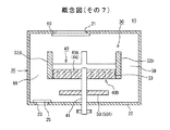
(概念説明その7)
図13に示す概念図は、図11に示す構成に加えて、回転羽根50Aを循環流促進部として追加した例である。循環流の促進効果を狙った構成例である。
(Conceptual explanation 7)
The conceptual diagram shown in FIG. 13 is an example in which a
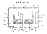
(概念説明その8)
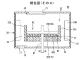
図14〜図16に示す概念図は、破砕機構40の固定破砕部40Bとしてスリット43を備えた円盤42と、スリット構成の内筒30をそれぞれ使用した例であり、そのうち図14はこれらの構成に加えてさらに促進板50Bを使用して循環流の促進効果を狙った構成例である。円盤42の構成およびスリット付きの内筒30の構成さらには促進板50Bの構成は、何れも前述した構成と同一構成のものが使用される。
(Conceptual explanation 8)
The conceptual diagrams shown in FIGS. 14 to 16 are examples in which a
このように構成することで、円盤42のスリット43と内筒30のスリット35とによる相乗の破砕によって、破砕処理が一層促進されると共に、十分な循環流も発生させることができるから、破砕処理時間の短縮などを達成できる。
By comprising in this way, a crushing process is further accelerated | stimulated by the synergistic crushing by the
(概念構成その9)
図15は図14の構成に対して、回転破砕部40Aと固定破砕部として機能する円盤42との上下配置関係を逆転させた構成例である。その効果は図14とほぼ同じである。
(Conceptual composition 9)
FIG. 15 is a configuration example in which the vertical arrangement relationship between the rotary crushing
(概念構成その10)
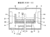
図16の概念図は、図14の構成にさらに回転羽根50Aを循環流促進部50として追加した構成例である。図14の構成よりも循環流が一層効果的に発生するため破砕処理時間の一層の短縮効果などが得られることになる。
(Conceptual composition 10)
The conceptual diagram of FIG. 16 is a configuration example in which a
(循環型破砕機構を搭載したトイレ装置)
続いて、上述した循環型破砕機構10を適用した装置の具体例として、この循環型破砕機構10を搭載したこの発明に係るトイレ装置を説明する。トイレ装置に搭載した循環型破砕機構10としては図16の内容を具体化したものである。破砕処理を適用したトイレ装置としては、特に可搬型で室内でも使用できるようにした簡易トイレ装置に適用した場合である。
(Toilet device equipped with a circulating crushing mechanism)
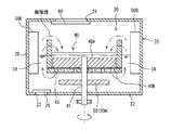
Subsequently, a toilet apparatus according to the present invention equipped with the circulation
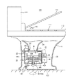
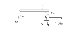
図17を参照して簡易トイレ装置100を説明する。
The
この簡易トイレ装置100は、便器本体110と、この便器本体110の下面側の投入口21に取り付けられた循環型破砕機構10とで構成される。循環型破砕機構10の構成は前述した通りであるが、詳細な構成は後述する。この循環型破砕機構10には粒状化された破砕物を下水管側に圧送するための圧送手段150を備える。
The
便器本体110はその外観は通常の便器とほぼ同じであって、陶器製でも金属製でも樹脂成型品でもよいが、可搬性を考慮すると樹脂成型品が好ましい。便器本体110の上部開口部は座部111となされ、この座部111には便座112が開閉自在に取り付けられ、便座112を覆うように便座蓋113が位置する。座部111の一端部には給水タンク114が設置される。給水タンク114には水道管(図示はしない)から水道水が給水される。
The
便器本体110の内部には、座部111から連なって概略漏斗状をなす誘導筒部120が位置する。誘導筒部120の下端開口部121に、循環型破砕機構10が取り付け固定される。そのため、この下端開口部121が循環型破砕機構10に設けられた投入口21に臨むように、しかも液密となるように取り付け固定される。
Inside the toilet
循環型破砕機構10は便器本体110の底部122に、ガタ付かないように取り付け固定されるが、その固定部材については図示しない。
Although the circulation
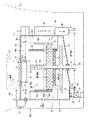
循環型破砕機構10は上述したように筒状本体20を有する。図18に示すように筒状本体20の投入口21には投入口用の開閉蓋61を備えた開閉機構60が設けられる。この開閉蓋61はスライド駆動部80によってスライドさせることで開閉が行われる。一方排出口23には閉止弁部材の一部として機能する排出口用の閉塞蓋25が回動自在に設けられる。排出口23と下水管との間には連結管86が配管され、この連結管86に閉止弁部材の一部として機能する電磁弁85が取り付けられて破砕水の制御が行われる。
The circulation
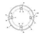
筒状本体20の内部には内筒30と、破砕機構40が設置される。破砕機構40は上述したように回転破砕部40Aと固定破砕部40Bとで構成され、回転破砕部40Aに設けられた回転軸41は底部22の外側まで導出され、その端部に設けられたプーリ89を介して駆動モータ90からの回転力がこの回転軸41に伝達される構成となっている。破砕機構40に関連して回転羽根50Aと促進板50Bからなる循環流促進部50が設けられている。
An
図18は上述した循環型破砕機構40の詳細を示す要部断面図である。すでに説明した部分で説明を要しない箇所は、その詳細説明を割愛する。内筒30を筒状本体20に取り付け固定する具体例を図19以下を参照して説明する。
FIG. 18 is a cross-sectional view of the main part showing the details of the circulation
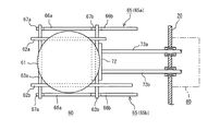
図19は循環流促進部50として使用される循環流促進板50Bの一例である。この促進板50Bは所定の幅(厚み)を有する樹脂成型品からなるほぼL字状をなす板体であって、その長辺部の一側面(図19では前面)にはガイド溝(係合溝)56が形成される。ガイド溝56は促進板50Bの中央部であって、その頭部からL字部55の端面58に至るまで形成される。端面58とガイド溝56との間には突部57が形成される。この突部57の高さは、固定破砕部40Bとして機能する円盤42の厚みとほぼ同じ高さか、若干高めに選定される。
促進板50Bの幅Lが筒状本体20と内筒30との間隙となるので、幅Lが間隙59の幅を決めることになる。
FIG. 19 shows an example of a circulation
Since the width L of the
このように構成された促進板50Bを一例として合計4枚使用して、図20に示すように筒状本体20の内面にほぼ90°の角間隔で取り付け固定される。この場合L字部55が下方に来るように、そして筒状本体20の底部22から所定の距離だけ離隔するように取り付け固定される。
A total of four
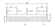
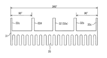
一方、内筒30は図21に平面図として、図22にその展開図として示すように、内筒本体31の周面に沿って複数のスリット35が形成される。この例では、同じ長さで、同じ幅のスリット35が一定の間隔をもって複数形成される。このとき内筒本体31の下端面側が解放されるようにスリット35が形成される。
On the other hand, the
スリット35の長さや幅は、破砕物である汚物に基づいて経験則から定められるもので、この例ではその長さは約30mm、幅は2〜4mm、間隔は4〜6mmに選定される。
The length and width of the
一方、内筒本体31と一体形成された係合片32は内筒本体31の外周壁面より上方へ突出するように設けられたもので、その幅はガイド溝56の幅とほぼ同じに選定される。
On the other hand, the
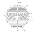
固定破砕部として機能する円盤42の構成例を図23に示す。この円盤42には複数のスリット43がその厚み方向を貫通して形成される。スリット43は図23の紙面左右方向に延在するスリット43aが円盤42の上下部に形成され、紙面の斜め方向に斜交して延在するスリット43bがその中央部に形成される。したがって、スリット43a,43bの長さはそれぞれ異なる。スリット43の幅は内筒30に形成されたスリット35の幅とほぼ同じである。なお、この例では円盤42の直径は15〜20cmの大きさのものが使用されている。
A configuration example of the
円盤42の外周面であって、ほぼ90°の間隔をもって係合凹部45(45a〜45d)が形成される。係合凹部45の深さおよび幅は、上述した循環流促進板50Bの突部57の長さと幅にほぼ等しくされている。円盤42の厚みは、突部57の高さに等しいか、若干薄く選定される。この例では僅かに薄い円盤42を使用した場合を示す。
Engagement recesses 45 (45a to 45d) are formed on the outer peripheral surface of the
回転破砕部40Aの一例を図24および図25に示す。
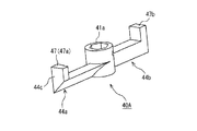
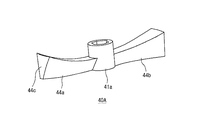
図24および図25に示すように、回転破砕部として機能する回転破砕部40Aは、回転軸41が貫通するハブ41aを中心にして左右に延びる帯状の腕44a,44bを備え、腕44a,44bは、若干ハブ41aの軸心から図24の紙面上下方向にシフトするように成型される。それぞれの腕44a,44bは回転方向に対して内側に反り返るようなくさび状をなし、円盤42との摺接端面が尖鋭端面となるように成型されている。このようにくさび状をなす腕44a,44bとしたのは、腕44a,44bに当たった破砕物を、円盤42側に押しつけて破砕物を効率よく破砕するためである。そして左右端面44c側は内筒30の内周面とほぼ摺接するような衝立部47(47a,47b)となされているが、これは内筒30の内周面側に押し出された破砕物をできるだけ前面(回転方向)の破砕刃側に押し出すためである。
An example of the rotary crushing
As shown in FIGS. 24 and 25, the
したがって、回転破砕部40Aは図26および図27に示すようなプロペラ状に多少湾曲させた腕44a,44bであっても同様な破砕力を付与できる。図26の場合には衝立部47の代わりに左右端面側が肉厚となるように設計されている。
Therefore, even if the
このような寸法関係に選定された回転破砕部40Aが回転軸41に固定されると共に、円盤42および内筒30が循環流促進板50Bを利用して筒状本体20内に固定される。図28はこれら三者の関係を示すもので、円盤42の係合凹部45が循環流促進板50Bに設けられた突部57に係合されて、円盤42が端面58に載置固定される。その後で内筒30の係合片32がガイド溝56をガイドとして循環流促進板50B内に装着固定される。
The
その結果、図20に示すように内筒30は循環流促進板50Bによって筒状本体20に対し所定の間隙59を保持して取り付け固定される。また図28に示すように円盤42と回転破砕部40Aの下端面とが少許の間隙を保持して対向するように回転破砕部40Aが回転軸41に取り付け固定される。これによって回転破砕部40Aと固定破砕部40Bからなる破砕機構40が得られる。また、内筒30の内周面と回転破砕部40Aの左右端面とが少許の間隙を保持して対向するように配置されるので、内筒30と回転破砕部40Aとによっても破砕部が得られるので、相乗の構成(二重構成)の破砕機構40が得られる。
As a result, as shown in FIG. 20, the
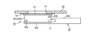
上述した筒状本体20の投入口21には投入口21の裏側を閉塞するように開閉機構60がスライド自在に取り付けられる。図29以下はこの開閉機構60の構成例を示す。
An opening /
図29および図30は投入口21を含めた開閉機構60の断面図であって、投入口21の内径状(円形)に合わせて、同じくこの内径よりも径大で、薄い円盤状開閉蓋61を有する。円盤状開閉蓋61の下面であって、円周部付近には、一対の補助板62a,62bが並んで垂設される。
FIGS. 29 and 30 are cross-sectional views of the opening /
垂設された補助板62a,62bの前後する位置には、図32に示すようにこれら補助板62a,62bに差し渡ってその先端部がそれぞれ補助板62a,62bの外面側に突出するように、一対のスライド棒63a,63bが取り付けられる。スライド棒63a,63bは取り付けられる位置が異なり、前方のスライド棒63aが下側であるときは、後方のスライド棒63bは上側(開閉蓋61側)となるように取り付けられる。開閉蓋61に対する横圧力(密着力)を高めるためである。
As shown in FIG. 32, the
スライド棒63a,63bは一対のガイド板65a,65bの板面に摺動自在に載置される。ガイド板65a,65bは何れも筒状本体20の頭部下面(天井)26a(図18)に取り付け固定される。開閉蓋61はこれらガイド板65a,65bにそれぞれガイドされながら進退(スライド)する。
The slide bars 63a and 63b are slidably mounted on the plate surfaces of the pair of
一対のガイド板65a、65bは同一構成であるので、ガイド板65aについて説明する。このガイド板65aは、前方のスライド棒63aをガイドする前ガイド面66aと、後方のスライド棒63bをガイドする後ガイド面66bとで構成される。スライド棒63a,63bの取り付け位置に合わせて、前ガイド面66aはガイド板65aの前方に形成されるのに対して、これよりも後方であって、しかも上側に、段差を持たせて後ガイド面66bが形成される。
Since the pair of
前ガイド面66aと後ガイド面66bは、何れも同一構成であって、前ガイド面66aについて説明するならば、図31に示すように先端側(紙面左手側)が上方側(投入口21の側)に向かって若干上り傾斜するような斜面構成であり、その先端部が膨出部67aとなされている。
Both the
図30のように開閉蓋61が後退して投入口21が解放された状態にあるときは、開閉蓋61は筒状本体20の頭部下面26aに対して僅かに離れるように開閉機構60の取り付け位置が選定されている。
When the opening / closing
図31のように斜面構成とすると、開閉蓋61をスライドさせて投入口21に近づけることによって、投入口21は前ガイド面66aおよび後ガイド面66bに形成された斜面に沿いながらスライド(移動)することになるので、投入口21の周り(頭部下面26a側)に貼着されたシール片70に近づく。そして最終スライド長となる位置までスライドすると、スライド棒63a,63bはガイド面66a,66bの膨出部67a,67bに乗り上がる。その結果、開閉蓋61はシール片70側に押圧されて、このシール片70に完全に密着するから、開閉蓋61によって投入口21を完全に閉塞できる。
When the slope configuration is as shown in FIG. 31, the opening / closing
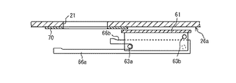
開閉蓋61の進退構成について以下に説明する。この例では一対の補助板62a,62bを貫くように係合棒71が取り付け固定される。図示する例は、後スライド棒63bの下側となる位置に取り付けられる。
The forward / backward configuration of the opening / closing
図32および図33に示すように、係合棒71には、係合駒72が係合固定される。係合駒72は矩形体であって、図32に示すように一対の補助板62a,62bの間に位置し、係合駒72の中央部には係合棒71が係着される係合溝72a(図33)を有する。係合駒72の側面には図33のように一対のロッド73a,73bが連結される。これらロッド73a,73bは筒状本体20の側面に取り付けられた駆動部80によってその進退が制御される。駆動部80はソレノイドなどを使用できる。ロッド73a,73bの進退位置はセンサ(図示はしない)によって監視される。駆動部80は圧縮空気によって作動するエアーシリンダを使用してもよい。
As shown in FIGS. 32 and 33, the
図18に示すように、筒状本体20の底部22は、排出口23側に傾斜した傾斜面となされ、破砕物や破砕水が排出口23に集まるようになされている。その底部22は閉塞蓋25が回転自在に取り付けられる。閉塞蓋25の回転軸83は底部22より外部に突出しており、そこにプーリ84が取り付けられ、筒状本体20の側部側に設置された駆動モータ90のプーリ91に対して、クラッチ機構を介して連結されることで、必要なタイミングのときだけ所定の開閉力を得ている。閉塞蓋25は破砕物の排出時のみ解放されるように、コントローラ(CPUを有した制御部)92の制御の下で制御される。
As shown in FIG. 18, the
連結管86は直接下水管に連結されるか、連結用ゴム管などが連結される。連結用ゴム管を用いる場合には、建物内に設置されたトイレ装置(固定された水栓トイレ装置)の便器内に破砕された汚物が排出される。
The connecting
図18に示すように、筒状本体20の上面には圧送手段150が載置固定される。圧送手段150は一例としてエアーコンプレッサが使用される。エアーコンプレッサ150と筒状本体20とはゴム管151によって連結され、エアーコンプレッサ150から送給される圧縮空気は筒状本体20内に導かれる。破砕物を下水管側に圧送して、筒状本体20内に破砕物や破砕水が残滓しないようにするためである。
As shown in FIG. 18, the pressure feeding means 150 is placed and fixed on the upper surface of the cylindrical
筒状本体20には、筒状本体内の水位を監視するための水位センサ93(図34参照)が取り付けられ、規定の水位以上に上昇しないように監視している。
A water level sensor 93 (see FIG. 34) for monitoring the water level in the cylindrical
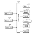
図34はトイレ装置100に備えられた破砕物処理のための制御系の一例を示す。この制御系は上述したようにCPUを備えた制御部200を有し、この制御部200には便座スイッチ116および洗浄スイッチ117からの信号が供給される。洗浄スイッチ117は、排便が終了した段階で利用者が操作するスイッチであり、通常は自動洗浄装置に備えられている洗浄スイッチが使用される。筒状本体20内の破砕水の水位を監視するために設けられた水位センサ93からのセンサ信号が供給される。
FIG. 34 shows an example of a control system for crushed material processing provided in the
制御部200ではこれらの入力信号に基づいて各種の処理が予め定められたタイミングに実行される。制御部200では駆動モータ90の制御が行われる。駆動モータ90は、少なくとも回転破砕部40Aの回転駆動、閉塞蓋25に対する開閉用クラッチ制御(クラッチは図示しない)などが行われる。制御部200では駆動部80による開閉蓋61の開閉制御が行われる。給水タンク114からの給水を制御するため、給水タンク114に備えられた給水弁95に対する開閉制御が行われる。図18には給水弁95は図示されていない。制御部200ではエアーコンプレッサ150による圧送制御が行われる。制御部200では、排出口23側に設けられた排出弁(電磁弁)85の制御が行われる。
The
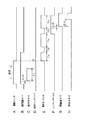
図35を参照して上述した制御タイミング例を説明する。用便のため便座112が開けられることで便座スイッチ116が便座蓋113の開放を検知すると(図35A)、開閉蓋61が開いて投入口21を開放する(図35B)。この開放タイミングより所定時間(Δta)遅れて給水弁95が開き、便器本体110の誘導筒部120を経由して水道水が破砕水用として筒状本体20内に注水される。注水量が所定量となると自動的に注水が休止する。注水量は筒状本体20内に設置された破砕機構40の一部を満たす程度の水量に設定されているが、破砕機構40の全体を満たすような水量に設定することができるので、任意の値を採り得る。注水量の監視はタイマ(図示はしない)によって行われる。上述した水位センサ93からのセンサ出力はどちらかと言えば注水量が規定量を超えないようにするため使用される。
An example of the control timing described above will be described with reference to FIG. When the
開閉蓋61を開くことで使用者の排便行為が実行されるが、上述のタイミングではこの排便行為とほぼ同じタイミングに注水処理がなされる。これは誘導筒部120の表面や、筒状本体20内を水道水で予め濡らしておくことで、排便ができるだけこれらに付着しないようにするためである。排便行為は給水期間よりも長くかかることが多いので、図35のタイミングはその例に因った。
Although the user's defecation action is executed by opening the open /
排便行為が終了して便座スイッチ116が便座蓋113の閉止状態を検知すると、洗浄スイッチ117が操作されて洗浄処理つまり破砕処理が開始される(図35D)。そのためまず、洗浄スイッチ117がオンすると駆動モータ90が制御される(図35E)。最初は期間Taに亘り低速回転による低速破砕処理である。破砕物である汚物の固まりを破砕するときの負荷を考慮して、最初は回転破砕部40Aを低速回転させる。そして所定時間Tb休止させてから期間Tcに亘り高速破砕処理に移る。
When the defecation action ends and the
開閉蓋61はこの低速破砕処理が終了した段階で閉じられる(図35B)。これは高速破砕処理のときは、破砕物が飛び散ることも考えられることを考慮したためと、臭気が室内に放出されないようにするためである。
The opening / closing
この高速破砕処理によって破砕物である汚物はほぼ完全に破砕されて粒状となる。低速破砕処理時、高速破砕処理時を問わず、筒状本体20内では循環流が生じているので破砕処理時間は短い。高速破砕処理が終了すると、再び期間Tbだけ休止したのち、今度は高速破砕処理時間と同じ時間Tcをかけて低速による破砕処理を行う(図35E)。汚物を確実に破砕して粒状化するためである。
By this high-speed crushing process, the filth that is crushed is almost completely crushed and becomes granular. Regardless of the low-speed crushing process or the high-speed crushing process, the crushing process time is short because a circulating flow is generated in the
高速破砕処理が終了した段階でエアーコンプレッサ150が駆動されて筒状本体20内に圧送媒体としての圧縮空気が送給され、筒状本体20の内圧を高める(図35F)。圧縮空気を送り、その内圧がある程度高まった時点、この例では2度目の低速破砕処理が開始されるタイミングよりも若干(Δtb)遅れた時点で、排出口23を塞いでいた閉塞蓋25を開ける(図35G)。閉塞蓋25を開けると破砕水が連結管86内を満たす。そして閉塞蓋25の開閉タイミングよりさらにΔtc遅れた時点で、排出弁(電磁弁)85を開ける(図35H)。
When the high-speed crushing process is completed, the
排出弁85を開けると、筒状本体20内の破砕物は破砕水を含めて一気に排出管側に圧送・排出される。排出弁85をオープンにした段階でもエアーコンプレッサ150からの圧縮空気の送給は継続され、しかも破砕機構40は低速破砕処理を維持するため、破砕物は確実に下水管側に排出される。その結果、筒状本体20内は綺麗に清掃されるため、破砕物の残滓は極めて少ない。
When the
2度目の低速破砕処理が実行されるまでは、排出口23が閉塞蓋25で閉じられているが、これは1度目の低速破砕処理や高速破砕処理のタイミングでは、充分に破砕されていない破砕物が排出口23内に沈下するおそれがある。そうすると連結管86や下水管が詰まるおそれがある。これを回避するためにできるだけ汚物が細断された後に排出口23を開くようにしたものである。
Until the second low-speed crushing process is executed, the
上述した各種の設定時間は自由に設定できるが、一例として遅延時間Δtaは2〜3秒程度、給水時間T1は10〜20秒程度、低速破砕処理時間Taは5〜15秒程度、休止時間Tbは1〜3秒程度、高速破砕処理時間Tbは5〜15秒程度、遅延時間Δtbは1〜2秒程度、遅延時間Δtcは2〜3秒程度に設定することができる。 The various set times described above can be set freely. As an example, the delay time Δta is about 2-3 seconds, the water supply time T1 is about 10-20 seconds, the low speed crushing treatment time Ta is about 5-15 seconds, and the downtime Tb. Can be set to about 1 to 3 seconds, the high-speed crushing treatment time Tb can be set to about 5 to 15 seconds, the delay time Δtb can be set to about 1 to 2 seconds, and the delay time Δtc can be set to about 2 to 3 seconds.
このような破砕処理タイミングとすることで、汚物を破砕して排出することができる。この破砕処理タイミングは一例であるので、種々の変形が可能である。例えば、2度目の低速破砕処理が終了し、破砕物を排出してから、所定時間だけ給水して洗浄処理を行ってもよい。このときは、回転破砕部40Aを低速回転させておくとよい。
By setting it as such a crushing process timing, a filth can be crushed and discharged. Since this crushing processing timing is an example, various modifications are possible. For example, after the second low-speed crushing process is completed and the crushed material is discharged, the cleaning process may be performed by supplying water for a predetermined time. At this time, the
低速破砕処理時と、高速破砕処理時とでは回転破砕部40Aの回転方向を反転制御してもよいし、同じ破砕処理時間内でも反転制御を行うことは可能である。
The rotation direction of the rotary crushing
トイレ装置100が可搬型であっても、同じ場所で使用される場合は据え置き型と変わらない。このような場所で使用される場合には、固定式のトイレ装置の場合と同じく、筒状本体20内に溜め水を貯留しておくこともできる。したがってこの場合には便座スイッチ116のタイミングに合わせて給水を行わず、排出処理後に洗浄を兼ねた給水を行って溜め水することになる。
Even if the
また、便座スイッチ116のタイミングに合わせて給水を行うのではなく、破砕処理が開始される直前のタイミングから所定量となるまで注水を行ってもよい。この場合には開閉蓋61が空いている時間内に所定の注水量となるように水量の調整が行われる。
Instead of supplying water in accordance with the timing of the
開閉蓋61は高速破砕処理時に閉じるように制御されているが、1度目の低速破砕処理に同期して開閉蓋61を閉じるように制御することもできる。
Although the open /
トイレ装置100には給水タンク114が備わっているが、給水タンク114を省略する代わりに、バキュームブレーカを介して水道水を直接便器本体110に供給するように構成することもできる。
Although the
排出口23は連結管86を介して下水管側に連結する他、既存のトイレ装置(固定式のトイレ装置)に導く構成でもよい。何れの場合でも、排出される破砕物は細断され、粒状化され、そして圧送して排出するため、破砕物の詰まりがなくなり、下水管までの連結管や導管(ゴム管)などの管径は細いものを利用できる。
The
循環型破砕機構10を適用することで破砕処理時間が短縮される。循環型破砕機構10を小型、簡素に設けることができるので簡易トイレ装置100へ循環型破砕機構10を設けることが容易である。
By applying the circulation
上述したトイレ装置100は、固定式の水洗トイレ装置にも適用できるのは言うまでもない。固定式のトイレ装置にこの発明を適用する場合には、圧送手段150は特に必要ではない。給水タンク114は既存のタンクを流用できる。
Needless to say, the
この発明では、野菜、食物などを破砕する破砕装置や、この破砕装置を備えたトイレ装置に適用できる。 In this invention, it is applicable to the crushing apparatus which crushes vegetables, food, etc., and the toilet apparatus provided with this crushing apparatus.
10・・・破砕機構、20・・・筒状本体、30・・・内筒、40・・・破砕機構、40A・・・回転破砕部(回転破砕刃)、40B・・・固定破砕部、42・・・円盤、50・・・循環流促進部、21・・・投入口、23・・・排出口、150・・・圧送手段、100・・・トイレ装置、110・・・便器本体、25,61・・・開閉蓋、35・・・スリット
DESCRIPTION OF
Claims (23)
上記筒状本体の内部に、所定の間隙を保持して取り付けられた内筒と、
上記内筒の内側に設けられた破砕機構とからなり、
上記破砕機構は、回転破砕部と、該回転破砕部と対向するように設けられた固定破砕部と、上記回転破砕部の駆動部とで構成され、
上記内筒と上記筒状本体との間に循環流を形成しながら、上記破砕機構によって上記破砕物を破砕するようにした
ことを特徴とする循環型破砕機構。 A cylindrical body having an inlet for crushed material and an outlet for the crushed material;
An inner cylinder attached with a predetermined gap inside the cylindrical main body; and
It consists of a crushing mechanism provided inside the inner cylinder,
The crushing mechanism includes a rotary crushing unit, a fixed crushing unit provided to face the rotary crushing unit, and a drive unit of the rotary crushing unit.
A circulation type crushing mechanism characterized by crushing the crushed material by the crushing mechanism while forming a circulation flow between the inner cylinder and the cylindrical main body.
ことを特徴とする請求項1記載の循環型破砕機構。 The circulation type crushing mechanism according to claim 1, further comprising a circulation flow promoting unit that cooperates with the crushing mechanism.
ことを特徴とする請求項2記載の循環型破砕機構。 The circulation type crushing mechanism according to claim 2, wherein the circulation flow promoting unit is a rotary blade that rotates in synchronization with the rotary crushing unit.
ことを特徴とする請求項2記載の循環型破砕機構。 The circulation type crushing mechanism according to claim 2, wherein the circulation flow promoting unit is one or more circulation flow promotion plates provided in the gap.
ことを特徴とする請求項4記載の循環型破砕機構。 The circulation type crushing mechanism according to claim 4, wherein the circulation flow promoting plate is also used as a fixing plate for fixing the inner cylinder to the cylindrical main body.
ことを特徴とする請求項1記載の循環型破砕機構。 The circulating crushing mechanism according to claim 1, wherein the rotary crushing section is a strip crushing blade.
ことを特徴とする請求項1記載の循環型破砕機構。 The circulating crushing mechanism according to claim 1, wherein the fixed crushing portion is provided on an upper surface side or a lower surface side of the rotary crushing portion.
ことを特徴とする請求項1記載の循環型破砕機構。 The circulating crushing mechanism according to claim 1, wherein the fixed crushing part is a disk having a large number of apertures.
ことを特徴とする請求項1記載の循環型破砕機構。 The circulating crushing mechanism according to claim 1, wherein the fixed crushing portion is provided in a part of the inner cylinder.
ことを特徴とする請求項1記載の循環型破砕機構。 The circulation type according to claim 1, wherein the fixed crushing portion includes a plurality of apertures or slits provided on a peripheral surface of the inner cylinder facing a peripheral surface of the rotary crushing portion. Crushing mechanism.
ことを特徴とする請求項1記載の循環型破砕機構。 The circulating crushing mechanism according to claim 1, wherein an opening / closing lid is provided at the inlet.
上記閉止弁部材は、少なくとも上記破砕機構の破砕処理の間、閉止状態にある
ことを特徴とする請求項1記載の循環型破砕機構。 A closing valve member is provided in the vicinity of the discharge port,
The circulating crushing mechanism according to claim 1, wherein the closing valve member is in a closed state at least during crushing processing of the crushing mechanism.
上記便器本体の下面側の開口部に取り付けられた循環型破砕機構とで構成され、
上記循環型破砕機構は、
上記開口部と対向する位置に設けられた汚物の投入口と、該汚物の排出口とを有する筒状本体と、
上記投入口と対峙すると共に、上記筒状本体の内部に所定の間隙を保持して取り付けられた内筒と、
上記内筒の内側に設けられた破砕機構とからなり、
上記破砕機構は、回転破砕部と、該回転破砕部と対向するように設けられた固定破砕部と、上記回転破砕部の駆動部とで構成され、
上記内筒と上記筒状本体との間に循環流を形成しながら上記破砕機構によって上記汚物を破砕して、上記排出口より排出するようにした
ことを特徴とするトイレ装置。 The toilet body,
It consists of a circulation type crushing mechanism attached to the opening on the lower surface side of the toilet body,
The circulating crushing mechanism is
A cylindrical body having a waste inlet provided at a position facing the opening, and a waste outlet;
An inner cylinder facing the input port and attached with a predetermined gap inside the cylindrical main body,
It consists of a crushing mechanism provided inside the inner cylinder,
The crushing mechanism includes a rotary crushing unit, a fixed crushing unit provided to face the rotary crushing unit, and a drive unit of the rotary crushing unit.
A toilet apparatus characterized in that the filth is crushed by the crushing mechanism while a circulating flow is formed between the inner cylinder and the cylindrical main body, and is discharged from the outlet.
上記汚物の破砕処理中若しくは上記汚物の破砕処理終了直後から上記便器本体内に上記圧送手段によって圧送媒体を供給して、破砕された上記汚物を上記排出口より下水管側に圧送するようにした
ことを特徴とする請求項13記載のトイレ装置。 The toilet body is provided with a pressure feeding means,
The pressure feeding medium is supplied by the pressure feeding means into the toilet body immediately after the filth crushing process or immediately after the filth crushing process is completed, and the crushed filth is pressure-fed from the discharge port to the sewage pipe side. The toilet device according to claim 13.
ことを特徴とする請求項13記載のトイレ装置。 The toilet device according to claim 13, wherein the toilet body is fixed or portable.
ことを特徴とする請求項13記載のトイレ装置。 The toilet apparatus according to claim 13, further comprising a circulation flow promoting unit that cooperates with the crushing mechanism.
ことを特徴とする請求項16記載のトイレ装置。 The toilet device according to claim 16, wherein the circulation flow promoting unit is a rotary blade that rotates in synchronization with the rotary crushing unit.
ことを特徴とする請求項16記載のトイレ装置。 The toilet device according to claim 16, wherein the circulation flow promoting unit is one or more circulation flow promotion plates provided in the gap.
ことを特徴とする請求項13記載のトイレ装置。 The toilet device according to claim 13, wherein the fixed crushing part is a disk having a large number of apertures.
ことを特徴とする請求項13記載のトイレ装置。 The toilet device according to claim 13, wherein the fixed crushing unit is configured by a large number of apertures or slits provided on a peripheral surface of the inner cylinder facing a peripheral surface of the rotary crushing unit. .
ことを特徴とする請求項13記載のトイレ装置。 The toilet apparatus according to claim 13, wherein an opening / closing lid is provided at the charging port.
上記閉止弁部材は、少なくとも上記破砕機構の破砕処理の間、閉止状態にある
ことを特徴とする請求項13記載のトイレ装置。 A closing valve member is provided in the vicinity of the discharge port,
The toilet device according to claim 13, wherein the closing valve member is in a closed state at least during the crushing process of the crushing mechanism.
上記閉止弁部材は、
少なくとも上記破砕機構の破砕処理の間、閉止状態にあるとともに、
上記閉止弁部材は、上記圧送手段から上記圧送媒体が供給されたのち、開弁状態となる
ことを特徴とする請求項14記載のトイレ装置。 A closing valve member is provided in the vicinity of the discharge port,
The closing valve member is
At least during the crushing process of the crushing mechanism,
The toilet device according to claim 14 , wherein the closing valve member is opened after the pumping medium is supplied from the pumping means.
Priority Applications (2)
| Application Number | Priority Date | Filing Date | Title |
|---|---|---|---|
| JP2006269194A JP5017993B2 (en) | 2006-09-29 | 2006-09-29 | Circulation type crushing mechanism and toilet equipment |
| PCT/JP2007/068829 WO2008038720A1 (en) | 2006-09-29 | 2007-09-27 | Circulation type fragmenting means and toilet apparatus |
Applications Claiming Priority (1)
| Application Number | Priority Date | Filing Date | Title |
|---|---|---|---|
| JP2006269194A JP5017993B2 (en) | 2006-09-29 | 2006-09-29 | Circulation type crushing mechanism and toilet equipment |
Publications (3)
| Publication Number | Publication Date |
|---|---|
| JP2008086880A JP2008086880A (en) | 2008-04-17 |
| JP2008086880A5 JP2008086880A5 (en) | 2009-07-30 |
| JP5017993B2 true JP5017993B2 (en) | 2012-09-05 |
Family
ID=39230155
Family Applications (1)
| Application Number | Title | Priority Date | Filing Date |
|---|---|---|---|
| JP2006269194A Expired - Fee Related JP5017993B2 (en) | 2006-09-29 | 2006-09-29 | Circulation type crushing mechanism and toilet equipment |
Country Status (2)
| Country | Link |
|---|---|
| JP (1) | JP5017993B2 (en) |
| WO (1) | WO2008038720A1 (en) |
Families Citing this family (10)
| Publication number | Priority date | Publication date | Assignee | Title |
|---|---|---|---|---|
| JP5017993B2 (en) * | 2006-09-29 | 2012-09-05 | マックス株式会社 | Circulation type crushing mechanism and toilet equipment |
| JP2010209654A (en) * | 2009-03-12 | 2010-09-24 | Max Co Ltd | Toilet apparatus |
| JP5146374B2 (en) * | 2009-03-12 | 2013-02-20 | マックス株式会社 | Toilet equipment |
| KR101271459B1 (en) * | 2011-05-23 | 2013-06-05 | (주)제이하우스 | Direct water dispose System every time we get Sewage |
| ES2574666T3 (en) * | 2011-06-27 | 2016-06-21 | Miltenyi Biotec Gmbh | Tissue fragment device |
| KR101665364B1 (en) | 2014-05-02 | 2016-10-24 | 주윤식 | Chamber Pot crushing wash out Foods Waste |
| CN104213623B (en) * | 2014-06-21 | 2017-02-08 | 浙江科助达机械科技有限公司 | Water closet rotary impeller container |
| CN106902911B (en) * | 2017-03-21 | 2019-02-12 | 重庆信海科技有限公司 | A hydraulic engineering crushing device |
| CN111774158A (en) * | 2020-07-10 | 2020-10-16 | 刘丽华 | Waste recovery equipment for highway construction |
| JP2025028495A (en) * | 2023-08-18 | 2025-03-03 | パナソニックIpマネジメント株式会社 | Pressure-feed toilet device |
Family Cites Families (10)
| Publication number | Priority date | Publication date | Assignee | Title |
|---|---|---|---|---|
| JPS4837578U (en) * | 1971-09-07 | 1973-05-08 | ||
| JPH01203055A (en) * | 1988-02-10 | 1989-08-15 | Hitachi Ltd | Meat chiyotsupa |
| JPH03290533A (en) * | 1990-04-05 | 1991-12-20 | Yagishita:Kk | Wash water recirculating flush toilet system |
| JPH07163899A (en) * | 1993-12-14 | 1995-06-27 | Nippondenso Co Ltd | Garbage-processing apparatus attached to sink |
| JPH09276730A (en) * | 1996-04-10 | 1997-10-28 | Hitachi Ltd | Garbage disposal equipment |
| JP3182352B2 (en) * | 1996-10-08 | 2001-07-03 | 神鋼造機株式会社 | Fiber material kneading and crushing equipment |
| JP2001104820A (en) * | 1999-10-07 | 2001-04-17 | Shinko Engineering Co Ltd | Top cover for waste crusher and screw crusher |
| JP2003093914A (en) * | 2001-09-26 | 2003-04-02 | Toto Ltd | Crushing apparatus and toilet drainage system using the same |
| JP4853815B2 (en) * | 2004-06-02 | 2012-01-11 | Toto株式会社 | Pumping toilet equipment |
| JP5017993B2 (en) * | 2006-09-29 | 2012-09-05 | マックス株式会社 | Circulation type crushing mechanism and toilet equipment |
-
2006
- 2006-09-29 JP JP2006269194A patent/JP5017993B2/en not_active Expired - Fee Related
-
2007
- 2007-09-27 WO PCT/JP2007/068829 patent/WO2008038720A1/en not_active Ceased
Also Published As
| Publication number | Publication date |
|---|---|
| JP2008086880A (en) | 2008-04-17 |
| WO2008038720A1 (en) | 2008-04-03 |
Similar Documents
| Publication | Publication Date | Title |
|---|---|---|
| WO2008038720A1 (en) | Circulation type fragmenting means and toilet apparatus | |
| WO2008053965A1 (en) | Circulating garbage disposal apparatus | |
| JP2009102980A (en) | Force-feed toilet device | |
| JP5648980B2 (en) | Pumping toilet equipment | |
| JP3714353B2 (en) | Water supply type dredge processing equipment | |
| CN101050640B (en) | Method for washing disposers | |
| CN115052693A (en) | Crushing device and dirt treatment device | |
| KR20090041801A (en) | Small Capacity Garbage Disposal Device | |
| KR100254075B1 (en) | Kitchen waste dealing apparatus | |
| US6969018B2 (en) | Sanitary shredder | |
| JP3849003B2 (en) | Pressure feeding device and toilet with pressure feeding device using the same | |
| JP4853815B2 (en) | Pumping toilet equipment | |
| JP2010227820A (en) | Garbage disposal device | |
| JP5282348B2 (en) | Garbage disposal equipment | |
| JP3614952B2 (en) | Disposer for soot processing | |
| JP2008126178A (en) | Circulation-type grinding and mixing device | |
| JP5954686B2 (en) | Pumping toilet equipment | |
| JP2005324196A (en) | Garbage treatment apparatus | |
| CN221864065U (en) | Full-automatic cat litter basin | |
| CN224142402U (en) | A residue crushing and discharge device for a lobster cleaning machine | |
| JP2006055786A (en) | Crushing device | |
| JP6064296B2 (en) | Pumping toilet equipment | |
| JP2007289799A (en) | Water supply apparatus for garbage treatment | |
| JP2003275608A (en) | Grinding treatment apparatus | |
| JP7426227B2 (en) | Sewage treatment equipment |
Legal Events
| Date | Code | Title | Description |
|---|---|---|---|
| A621 | Written request for application examination |
Free format text: JAPANESE INTERMEDIATE CODE: A621 Effective date: 20090310 |
|
| A521 | Written amendment |
Free format text: JAPANESE INTERMEDIATE CODE: A523 Effective date: 20090611 |
|
| RD02 | Notification of acceptance of power of attorney |
Free format text: JAPANESE INTERMEDIATE CODE: A7422 Effective date: 20110819 |
|
| A131 | Notification of reasons for refusal |
Free format text: JAPANESE INTERMEDIATE CODE: A131 Effective date: 20120214 |
|
| A521 | Written amendment |
Free format text: JAPANESE INTERMEDIATE CODE: A523 Effective date: 20120416 |
|
| TRDD | Decision of grant or rejection written | ||
| A01 | Written decision to grant a patent or to grant a registration (utility model) |
Free format text: JAPANESE INTERMEDIATE CODE: A01 Effective date: 20120515 |
|
| A01 | Written decision to grant a patent or to grant a registration (utility model) |
Free format text: JAPANESE INTERMEDIATE CODE: A01 |
|
| A61 | First payment of annual fees (during grant procedure) |
Free format text: JAPANESE INTERMEDIATE CODE: A61 Effective date: 20120528 |
|
| R150 | Certificate of patent or registration of utility model |
Free format text: JAPANESE INTERMEDIATE CODE: R150 |
|
| FPAY | Renewal fee payment (event date is renewal date of database) |
Free format text: PAYMENT UNTIL: 20150622 Year of fee payment: 3 |
|
| LAPS | Cancellation because of no payment of annual fees |