JP5017690B2 - Liquid crystal display - Google Patents

Liquid crystal display Download PDF

Info

Publication number
JP5017690B2
JP5017690B2 JP2007302040A JP2007302040A JP5017690B2 JP 5017690 B2 JP5017690 B2 JP 5017690B2 JP 2007302040 A JP2007302040 A JP 2007302040A JP 2007302040 A JP2007302040 A JP 2007302040A JP 5017690 B2 JP5017690 B2 JP 5017690B2
Authority
JP
Japan
Prior art keywords
liquid crystal
crystal display
display panel
light
opening
Prior art date
Legal status (The legal status is an assumption and is not a legal conclusion. Google has not performed a legal analysis and makes no representation as to the accuracy of the status listed.)
Active
Application number
JP2007302040A
Other languages
Japanese (ja)
Other versions
JP2009128519A (en
JP2009128519A5 (en
Inventor
健治 青島
Current Assignee (The listed assignees may be inaccurate. Google has not performed a legal analysis and makes no representation or warranty as to the accuracy of the list.)
Japan Display Central Inc
Original Assignee
Japan Display Central Inc
Priority date (The priority date is an assumption and is not a legal conclusion. Google has not performed a legal analysis and makes no representation as to the accuracy of the date listed.)
Filing date
Publication date
Application filed by Japan Display Central Inc filed Critical Japan Display Central Inc
Priority to JP2007302040A priority Critical patent/JP5017690B2/en
Publication of JP2009128519A publication Critical patent/JP2009128519A/en
Publication of JP2009128519A5 publication Critical patent/JP2009128519A5/ja
Application granted granted Critical
Publication of JP5017690B2 publication Critical patent/JP5017690B2/en
Active legal-status Critical Current
Anticipated expiration legal-status Critical

Links

Images

Description

この発明は、液晶表示装置に係り、特に、透過型の液晶表示パネル及びこれを照明する照明ユニットを備えた液晶表示装置に関する。   The present invention relates to a liquid crystal display device, and more particularly, to a transmissive liquid crystal display panel and a liquid crystal display device including an illumination unit that illuminates the transmissive liquid crystal display panel.

液晶表示装置は、軽量、薄型、低消費電力などの特徴を生かして、パーソナルコンピュータなどのOA機器や情報端末機器などの表示装置として各種分野で利用されている。近年では、液晶表示装置は、スロットマシンなどの遊技機にも利用されている。遊技機用に搭載される液晶表示パネルは、例えばその筐体の正面に設けられている。   Liquid crystal display devices are utilized in various fields as display devices for OA equipment such as personal computers and information terminal equipment, taking advantage of features such as light weight, thinness, and low power consumption. In recent years, liquid crystal display devices are also used in gaming machines such as slot machines. A liquid crystal display panel mounted for a gaming machine is provided, for example, on the front surface of the housing.

液晶表示パネルは、複数の表示画素を備え、画像を表示可能な表示部を有するとともに、その中央に筐体の内部に収納した表示媒体すなわち回転リールの配置位置に対応する略矩形状の透過部を有している。このような液晶表示パネルは、基本的には通常用途のものと同一構成である。液晶表示パネルと回転リールとの間に配置された照明ユニットは、液晶表示パネルの透過部に対応して、略矩形状の開口部を有している。このように構成することにより、回転リールの絵柄に基づいた抽選結果を外部から目視することが可能となる。   The liquid crystal display panel includes a plurality of display pixels, a display unit capable of displaying an image, and a substantially rectangular transmission unit corresponding to the position of the display medium housed in the housing, that is, the rotating reel, in the center thereof have. Such a liquid crystal display panel basically has the same configuration as that of a normal use. The illumination unit arranged between the liquid crystal display panel and the rotating reel has a substantially rectangular opening corresponding to the transmission part of the liquid crystal display panel. With this configuration, the lottery result based on the design of the rotating reel can be viewed from the outside.

このような液晶表示装置において、回転リールの視認性を改善することが要求されている。特に、特許文献1によれば、光反射シートや反射板が設けられない導光板の露出部分から光が漏れ出し、回胴リールの外周面を不要に照らしてしまうという課題に対して、光を吸収または反射する遮光部材が形成されたスリット状の溝を導光板の開口を囲むように配置する技術が開示されている。また、特許文献2によれば、リール窓部に光偏光パターンがないため、リール窓部の光量が不足するという課題に対して、切り抜きの端面に光散乱加工を施す技術が開示されている。
特開2005−185826号公報 特開2005−152661号公報
In such a liquid crystal display device, it is required to improve the visibility of the rotating reel. In particular, according to Patent Document 1, the light is leaked from the exposed portion of the light guide plate where the light reflection sheet or the reflection plate is not provided, and the light is unnecessarily illuminated on the outer peripheral surface of the spinning reel. A technique is disclosed in which a slit-like groove in which a light-shielding member that absorbs or reflects is formed so as to surround an opening of a light guide plate. Further, according to Patent Document 2, there is disclosed a technique for performing light scattering processing on an end face of a cut-out for the problem that the light amount of the reel window portion is insufficient because there is no light polarization pattern in the reel window portion.
JP 2005-185826 A JP 2005-152661 A

上述したような構成の液晶表示装置においては、液晶表示パネルと照明ユニットとの間の隙間から照明ユニットからの光が漏れ出てしまうことがある。このように漏れ出た光は、特に、液晶表示パネルを斜め方向から観察したときに視認される。このため、回転リールを斜め方向から見ようとしたときに、見栄えが悪化してしまう。また、液晶表示パネルと照明ユニットとの接触により、液晶ゆれ(プーリング)が生じることがある。したがって、液晶表示パネルの表示品位の低下を招くおそれがある。   In the liquid crystal display device having the above-described configuration, light from the illumination unit may leak from a gap between the liquid crystal display panel and the illumination unit. The leaked light is visually recognized particularly when the liquid crystal display panel is observed from an oblique direction. For this reason, when it tries to look at a rotating reel from the diagonal direction, the appearance will deteriorate. Further, liquid crystal shaking (pooling) may occur due to contact between the liquid crystal display panel and the lighting unit. Therefore, the display quality of the liquid crystal display panel may be deteriorated.

この発明は、上述した問題点に鑑みなされたものであって、その目的は、液晶表示パネルの表示品位を改善することが可能な液晶表示装置を提供することにある。   The present invention has been made in view of the above-described problems, and an object thereof is to provide a liquid crystal display device capable of improving the display quality of a liquid crystal display panel.

この発明の態様による液晶表示装置は、
透過型の液晶表示パネルと、
前記液晶表示パネルを背面側から照明する照明ユニットと、を備えた液晶表示装置において、
前記照明ユニットは、
矩形状の第1開口部を有する導光体と、
前記第1開口部と重なる第2開口部、及び、前記第1開口部の端面に対向する壁部を有し、前記導光体を保持するフレームと、
前記壁部の前記液晶表示パネルに対向する端部上に配置される緩衝材と、を備えたことを特徴とする。
A liquid crystal display device according to an aspect of the present invention includes:
A transmissive liquid crystal display panel;
In a liquid crystal display device comprising an illumination unit that illuminates the liquid crystal display panel from the back side,
The lighting unit is:
A light guide having a rectangular first opening;
A second opening that overlaps the first opening, and a wall that faces the end face of the first opening, and a frame that holds the light guide;
And a buffer material disposed on an end of the wall facing the liquid crystal display panel.

この発明によれば、液晶表示パネルの表示品位を改善することが可能な液晶表示装置を提供することができる。   According to the present invention, a liquid crystal display device capable of improving the display quality of a liquid crystal display panel can be provided.

以下、この発明の一実施の形態に係る液晶表示装置、特に遊技機用に利用可能な液晶表示装置について図面を参照して説明する。   Hereinafter, a liquid crystal display device according to an embodiment of the present invention, particularly a liquid crystal display device that can be used for gaming machines will be described with reference to the drawings.

図1及び図2に示すように、液晶表示装置1は、略矩形平板状の透過型の液晶表示パネル2を備えている。この液晶表示パネル2は、一対の基板すなわちアレイ基板3及び対向基板4と、これらの間に光変調層として保持された液晶層5と、によって構成されている。また、有効部6は、主に映像を表示可能に構成された映像表示部6Aと、後述する回転リール110を目視可能とする略矩形状の透過部6Bと、を有している。   As shown in FIGS. 1 and 2, the liquid crystal display device 1 includes a transmissive liquid crystal display panel 2 having a substantially rectangular flat plate shape. The liquid crystal display panel 2 includes a pair of substrates, that is, an array substrate 3 and a counter substrate 4, and a liquid crystal layer 5 held between them as a light modulation layer. The effective unit 6 includes a video display unit 6A configured to mainly display video, and a substantially rectangular transmission unit 6B that allows a rotary reel 110 to be described later to be viewed.

アレイ基板3は、有効部6において、表示画素PXの行方向に沿って延在する複数の走査線Y、表示画素PXの列方向に沿って延在する複数の信号線X、これらの走査線Yと信号線Xとの交差部付近において表示画素PX毎に配置されたスイッチング素子7、スイッチング素子7に接続された画素電極8などを備えている。   The array substrate 3 includes a plurality of scanning lines Y extending along the row direction of the display pixels PX, a plurality of signal lines X extending along the column direction of the display pixels PX, and the scanning lines in the effective unit 6. In the vicinity of the intersection of Y and the signal line X, a switching element 7 disposed for each display pixel PX, a pixel electrode 8 connected to the switching element 7, and the like are provided.

スイッチング素子7は、薄膜トランジスタ(TFT)などで構成されている。このスイッチング素子7のゲート電極7Gは、対応する走査線Yに電気的に接続されている(あるいは走査線と一体に形成されている)。スイッチング素子7のソース電極7Sは、対応する信号線Xに電気的に接続されている(あるいは信号線Xと一体に形成されている)。スイッチング素子7のドレイン電極7Dは、対応する表示画素PXの画素電極8に電気的に接続されている(あるいは画素電極8と一体に形成されている)。   The switching element 7 is composed of a thin film transistor (TFT) or the like. The gate electrode 7G of the switching element 7 is electrically connected to the corresponding scanning line Y (or formed integrally with the scanning line). The source electrode 7S of the switching element 7 is electrically connected to the corresponding signal line X (or formed integrally with the signal line X). The drain electrode 7D of the switching element 7 is electrically connected to the pixel electrode 8 of the corresponding display pixel PX (or formed integrally with the pixel electrode 8).

対向基板4は、有効部6において、全表示画素PXに共通の対向電極9などを備えている。画素電極8及び対向電極9は、インジウム・ティン・オキサイド(ITO)やインジウム・ジンク・オキサイド(IZO)などの光透過性を有する導電材料によって形成されている。   The counter substrate 4 includes a counter electrode 9 and the like common to all the display pixels PX in the effective portion 6. The pixel electrode 8 and the counter electrode 9 are formed of a light-transmitting conductive material such as indium tin oxide (ITO) or indium zinc oxide (IZO).

これらのアレイ基板3及び対向基板4は、それぞれの内面(アレイ基板3における画素電極8が配置された面及び対向基板4における対向電極9が配置された面)に配向膜10A及び10Bを備えている。アレイ基板3及び対向基板4は、配向膜10A及び10Bを対向させた状態で配設され、これらの間にギャップを形成する。液晶層5は、アレイ基板3と対向基板4とのギャップに封止された液晶組成物によって形成されている。   The array substrate 3 and the counter substrate 4 are provided with alignment films 10A and 10B on the inner surfaces (the surface of the array substrate 3 on which the pixel electrode 8 is disposed and the surface of the counter substrate 4 on which the counter electrode 9 is disposed). Yes. The array substrate 3 and the counter substrate 4 are arranged with the alignment films 10A and 10B facing each other, and a gap is formed between them. The liquid crystal layer 5 is formed of a liquid crystal composition sealed in the gap between the array substrate 3 and the counter substrate 4.

また、液晶表示パネル2において、アレイ基板3の外面及び対向基板4の外面には、それぞれ偏光板を含む光学素子OD1及びOD2が配置されている。   In the liquid crystal display panel 2, optical elements OD1 and OD2 including polarizing plates are disposed on the outer surface of the array substrate 3 and the outer surface of the counter substrate 4, respectively.

カラー表示タイプの液晶表示装置では、液晶表示パネル2は、複数種類の表示画素、例えば赤(R)を表示する赤色画素、緑(G)を表示する緑色画素、青(B)を表示する青色画素を有している。図2に示した例の液晶表示パネル2は、対向基板4の内面に、赤色画素に対応して赤色の主波長の光を透過する赤色カラーフィルタCRを備え、緑色画素に対応して緑色の主波長の光を透過する緑色カラーフィルタCGを備え、さらに、青色画素に対応して青色の主波長の光を透過する青色カラーフィルタCBを備えている。   In the color display type liquid crystal display device, the liquid crystal display panel 2 includes a plurality of types of display pixels, for example, a red pixel that displays red (R), a green pixel that displays green (G), and a blue that displays blue (B). Has pixels. The liquid crystal display panel 2 in the example shown in FIG. 2 includes a red color filter CR that transmits light having a red main wavelength corresponding to the red pixel on the inner surface of the counter substrate 4, and has a green color corresponding to the green pixel. A green color filter CG that transmits light of the main wavelength is provided, and further, a blue color filter CB that transmits light of the blue main wavelength corresponding to the blue pixel is provided.

このような構成の液晶表示パネル2は、矩形枠状のベゼルカバー11と照明ユニット15との間に配置されている。すなわち、照明ユニット15は、その表面を液晶表示パネル2の背面側(アレイ基板側)に対向させた状態で、液晶表示パネル2とともにベゼルカバー11と一体化されており、液晶表示パネル2を背面側から照明する。   The liquid crystal display panel 2 having such a configuration is disposed between the rectangular frame-shaped bezel cover 11 and the illumination unit 15. That is, the illumination unit 15 is integrated with the bezel cover 11 together with the liquid crystal display panel 2 with the surface thereof facing the back side (array substrate side) of the liquid crystal display panel 2, and the liquid crystal display panel 2 is Illuminate from the side.

液晶表示パネル2に駆動信号を供給するドライバ回路12は、フレキシブルなプリント配線基板13を介して液晶表示パネル2における一側縁に電気的に接続されている。このドライバ回路12は、プリント配線基板13を湾曲させることにより、照明ユニット15の裏面側に配置される。   A driver circuit 12 that supplies a drive signal to the liquid crystal display panel 2 is electrically connected to one side edge of the liquid crystal display panel 2 via a flexible printed wiring board 13. The driver circuit 12 is disposed on the back side of the illumination unit 15 by curving the printed wiring board 13.

図3に示すように、照明ユニット15は、光源部20、導光体21などを備えている。光源部20は、光源としての冷陰極管22及びランプリフレクタ23を備えて構成されている。すなわち、冷陰極管22は、矩形状の導光体21の長手方向に延在する細長い円筒状の光源である。ランプリフレクタ23は、冷陰極管22から放射された放射光を導光体21に向けて反射するものであり、冷陰極管22の周囲を取り囲むように配置されている。   As shown in FIG. 3, the illumination unit 15 includes a light source unit 20 and a light guide 21. The light source unit 20 includes a cold cathode tube 22 and a lamp reflector 23 as a light source. That is, the cold cathode tube 22 is an elongated cylindrical light source extending in the longitudinal direction of the rectangular light guide 21. The lamp reflector 23 reflects the radiated light emitted from the cold cathode tube 22 toward the light guide 21, and is disposed so as to surround the cold cathode tube 22.

導光体21は、光透過性を有するアクリル系樹脂やポリカーボネート系樹脂などの樹脂材料により形成されている。ここでは、導光体21は、略矩形状に成型されており、全体に亘って略均一な厚さDに形成されている。この導光体21は、液晶表示パネル2側に面した第1主面21bと、この第1主面21bに対向した第2主面21dと、これらの第1主面21bと第2主面21dとを接続する第1側面21a及び第2側面21cとを有している。   The light guide 21 is formed of a resin material such as an acrylic resin or a polycarbonate resin having light transmittance. Here, the light guide 21 is formed in a substantially rectangular shape, and is formed to have a substantially uniform thickness D throughout. The light guide 21 includes a first main surface 21b facing the liquid crystal display panel 2, a second main surface 21d facing the first main surface 21b, and the first main surface 21b and the second main surface. It has the 1st side 21a and the 2nd side 21c which connect 21d.

この実施の形態では、光源部20は、導光体21の一対の長辺21Eに沿って配置されている。すなわち、冷陰極管22は、導光体21の長辺21Eに沿った第1側面21a及び第2側面21cに対して略平行に対向するように配置されている。つまり、導光体21の第1側面21a及び第2側面21cは、冷陰極管22からの放射光が入射する光入射面に相当する。   In this embodiment, the light source unit 20 is disposed along a pair of long sides 21 </ b> E of the light guide 21. That is, the cold cathode tube 22 is disposed so as to face the first side surface 21a and the second side surface 21c along the long side 21E of the light guide 21 substantially in parallel. That is, the first side surface 21 a and the second side surface 21 c of the light guide 21 correspond to a light incident surface on which radiated light from the cold cathode tube 22 is incident.

このような構成の導光体21は、第1側面21a及び第2側面21cを介して入射した冷陰極管22からの放射光を伝搬し、第1主面21b及び第2主面21dから出射可能である。つまり、導光体21の第1主面21b及び第2主面21dは、導光体21の内部に入射した光を出射する出射面に相当する。   The light guide 21 having such a configuration propagates the emitted light from the cold cathode tube 22 incident through the first side surface 21a and the second side surface 21c and emits the light from the first main surface 21b and the second main surface 21d. Is possible. In other words, the first main surface 21 b and the second main surface 21 d of the light guide 21 correspond to an emission surface that emits light incident on the light guide 21.

略矩形状の光学シート24は、導光体21の第1主面21bを覆うように配置されている。この光学シート24は、導光体21の第1主面21bから出射された出射光に対して所定の光学特性を付与するものであり、例えば、第1主面21bからの出射光を集光する集光シート、及び、第1主面21bからの出射光を拡散する拡散シートなどである。なお、図3に示した例では、1枚の光学シート24のみを図示しているが、複数の光学シートを積層しても良い。   The substantially rectangular optical sheet 24 is disposed so as to cover the first main surface 21 b of the light guide 21. The optical sheet 24 gives a predetermined optical characteristic to the outgoing light emitted from the first main surface 21b of the light guide 21. For example, the optical sheet 24 collects the outgoing light from the first main surface 21b. And a diffusion sheet for diffusing the light emitted from the first main surface 21b. In the example shown in FIG. 3, only one optical sheet 24 is illustrated, but a plurality of optical sheets may be laminated.

また、略矩形状の光学シート25は、導光体21の第2主面21dを覆うように配置されている。この光学シート25は、導光体21の第2主面21dから出射された出射光を再び導光体21に向けて反射する反射シートである。なお、図3に示した例では、1枚の光学シート25のみを図示しているが、他の機能を有する光学シートをさらに追加しても良い。   The substantially rectangular optical sheet 25 is arranged so as to cover the second main surface 21 d of the light guide 21. The optical sheet 25 is a reflection sheet that reflects the emitted light emitted from the second main surface 21 d of the light guide 21 toward the light guide 21 again. In the example shown in FIG. 3, only one optical sheet 25 is illustrated, but an optical sheet having other functions may be further added.

これらの光源部20、導光体21、光学シート24及び25は、略矩形状のフレーム30に収容されている。   The light source unit 20, the light guide 21, and the optical sheets 24 and 25 are accommodated in a substantially rectangular frame 30.

上述したような構成の液晶表示装置は、以下のように動作する。すなわち、一対の光源部20の冷陰極管22に電気エネルギーを供給して、冷陰極管22を発光させる。これらの冷陰極管22から放射された線状の放射光の一部は、冷陰極管22を覆うランプリフレクタ23の内面にて反射され、それぞれ導光体21の第1側面21a及び第2側面21cに向けて導出される。また、放射光の一部は、直接第1側面21a及び第2側面21cに導かれる。第1側面21a及び第2側面21cから入射した入射光は、導光体21の内部を伝搬して、導光体21の第1主面21bに向けて屈折または反射される。導光体21の第2主面21dから漏れ出た光は、光学シート25により再び導光体21の内部に向けて反射される。   The liquid crystal display device configured as described above operates as follows. That is, electric energy is supplied to the cold cathode tubes 22 of the pair of light source units 20 to cause the cold cathode tubes 22 to emit light. Part of the linear radiation emitted from the cold cathode tubes 22 is reflected by the inner surface of the lamp reflector 23 that covers the cold cathode tubes 22, and the first side surface 21 a and the second side surface of the light guide 21, respectively. Derived toward 21c. In addition, part of the emitted light is directly guided to the first side surface 21a and the second side surface 21c. Incident light incident from the first side surface 21 a and the second side surface 21 c propagates through the light guide 21 and is refracted or reflected toward the first main surface 21 b of the light guide 21. The light leaking from the second main surface 21 d of the light guide 21 is reflected again toward the inside of the light guide 21 by the optical sheet 25.

導光体21の第1主面21bから出射された出射光は、光学シート24を通過する際に適度に集光されたり、適度に拡散されたりするなどの所定の光学特性が付与される。これにより、導光体21の第1主面21bから出射された出射光の輝度が向上され、且つ、均一化される。   The emitted light emitted from the first main surface 21b of the light guide 21 is given predetermined optical characteristics such as being appropriately condensed or moderately diffused when passing through the optical sheet 24. Thereby, the brightness | luminance of the emitted light radiate | emitted from the 1st main surface 21b of the light guide 21 is improved, and it is made uniform.

照明ユニット15からの照明光、すなわち光学シート24を通過した光は、液晶表示パネル2の裏面側に導出される。液晶表示パネル2に導出された照明光は、液晶表示パネル2の有効部6を選択的に透過する。これにより、液晶表示パネル2の有効部6に画像が表示される。   Illumination light from the illumination unit 15, that is, light that has passed through the optical sheet 24 is led out to the back side of the liquid crystal display panel 2. The illumination light derived to the liquid crystal display panel 2 selectively transmits through the effective portion 6 of the liquid crystal display panel 2. As a result, an image is displayed on the effective portion 6 of the liquid crystal display panel 2.

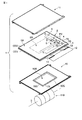
次に、スロットマシンなどの遊技機用として利用される液晶表示装置1について説明する。すなわち、図1及び図5に示すように、遊技機は、筐体100の内部において、可変表示する表示媒体として、回転自在に配置された回転リール110を備えている。この回転リール110は、回転軸Oを中心として回転可能な複数、例えば3個の円筒状のリール本体111を備えている。図1に示した例では、3個のリール本体111は、回転軸Oの延びる方向に沿って配列されている。各リール本体111の円筒面には、等間隔に配置された複数の絵柄を有する帯状のリールテープ112が貼付されている。   Next, the liquid crystal display device 1 used for a gaming machine such as a slot machine will be described. That is, as shown in FIGS. 1 and 5, the gaming machine includes a rotating reel 110 that is rotatably arranged as a display medium for variably displaying inside the housing 100. The rotary reel 110 includes a plurality of, for example, three cylindrical reel bodies 111 that can rotate about a rotation axis O. In the example shown in FIG. 1, the three reel bodies 111 are arranged along the direction in which the rotation axis O extends. A strip-shaped reel tape 112 having a plurality of patterns arranged at equal intervals is affixed to the cylindrical surface of each reel body 111.

液晶表示装置1は、筐体100の内部における回転リール110の前面側(すなわち観察者側)に配置されている。つまり、液晶表示パネル2は回転リール110の前面側に配置され、また、照明ユニット15は、液晶表示パネル2と回転リール110との間に配置されている。筐体100は、液晶表示装置1に表示された画像を目視可能とする窓部102を有しており、この窓部102にガラス板などの光透過性を有する保護板103を備えている。   The liquid crystal display device 1 is disposed on the front side (that is, the observer side) of the rotating reel 110 inside the housing 100. That is, the liquid crystal display panel 2 is disposed on the front side of the rotary reel 110, and the illumination unit 15 is disposed between the liquid crystal display panel 2 and the rotary reel 110. The housing 100 includes a window portion 102 that allows an image displayed on the liquid crystal display device 1 to be viewed, and the window portion 102 includes a protective plate 103 having a light transmission property such as a glass plate.

このような液晶表示装置1に搭載される照明ユニット15は、その略中央に回転リール110の配置位置に対応して開口部15Aを有している。開口部15Aは、一対の長辺15Lを有するとともにこれらの長辺に直交する一対の短辺15Sを有する略矩形形状である。   The illumination unit 15 mounted on the liquid crystal display device 1 has an opening 15 </ b> A corresponding to the position where the rotary reel 110 is disposed at the approximate center thereof. The opening 15A has a pair of long sides 15L and a substantially rectangular shape having a pair of short sides 15S orthogonal to the long sides.

すなわち、図3に示すように、導光体21は、回転リール110の配置位置に対応して略矩形状の開口部(第1開口部)21Aを有している。この開口部21Aは、長辺15Lのそれぞれに対応した長辺21L、及び、短辺15Sのそれぞれに対応した短辺21Sを有している。開口部21Aは、長辺21Lに沿った端面21Ga及び21Gc、短辺21Sに沿った端面21Gb及び21Gdの4つの端面21Gを有している。   That is, as shown in FIG. 3, the light guide 21 has a substantially rectangular opening (first opening) 21 </ b> A corresponding to the arrangement position of the rotary reel 110. The opening 21A has a long side 21L corresponding to each of the long sides 15L and a short side 21S corresponding to each of the short sides 15S. The opening 21A has four end surfaces 21G, which are end surfaces 21Ga and 21Gc along the long side 21L, and end surfaces 21Gb and 21Gd along the short side 21S.

また、光学シート24及び25もそれぞれ同様に、略矩形状の開口部24A及び25Aを有している。開口部24A及び25Aは、長辺15Lのそれぞれに対応した長辺24L、25L、及び、短辺15Sのそれぞれに対応した短辺24S、25Sを有している。   Similarly, the optical sheets 24 and 25 have substantially rectangular openings 24A and 25A, respectively. The openings 24A and 25A have long sides 24L and 25L corresponding to the long sides 15L and short sides 24S and 25S corresponding to the short sides 15S, respectively.

さらに、フレーム30も同様に、略矩形状の開口部(第2開口部)30Aを有している。開口部30Aは、長辺15Lのそれぞれに対応した長辺30L、及び、短辺15Sのそれぞれに対応した短辺30Sを有している。それぞれの開口部21A、24A、25A、及び30Aは、重なるように配置されている。   Further, the frame 30 similarly has a substantially rectangular opening (second opening) 30A. The opening 30A has a long side 30L corresponding to each of the long sides 15L and a short side 30S corresponding to each of the short sides 15S. The openings 21A, 24A, 25A, and 30A are arranged so as to overlap each other.

このように照明ユニット15に開口部15Aを形成することによって、照明ユニット15の背後に位置する回転リール110上の所定数の絵柄を目視可能としている。また、開口部15Aを形成することにより、導光体21の重量が軽減され、液晶表示装置1の軽量化が可能となる。   By forming the opening 15 </ b> A in the lighting unit 15 in this manner, a predetermined number of patterns on the rotary reel 110 located behind the lighting unit 15 can be visually observed. Further, by forming the opening 15A, the weight of the light guide 21 is reduced, and the weight of the liquid crystal display device 1 can be reduced.

ところで、液晶表示パネル2は、上述したように、有効部6において、映像表示部6A及び透過部6Bを有している。映像表示部6Aは、マトリクス状に配置された表示画素PX間にブラックマトリクスとして機能する第1遮光層BM1を備えている。また、図2に示した例のカラー表示タイプの液晶表示パネル2では、マトリクス状の複数の表示画素PXに対応して配置されたカラーフィルタ層C(R、G、B)を備えている。   By the way, as described above, the liquid crystal display panel 2 includes the video display unit 6A and the transmission unit 6B in the effective unit 6. The video display unit 6A includes a first light shielding layer BM1 that functions as a black matrix between display pixels PX arranged in a matrix. Further, the color display type liquid crystal display panel 2 of the example shown in FIG. 2 includes color filter layers C (R, G, B) arranged corresponding to a plurality of display pixels PX in a matrix form.

一方で、透過部6Bは、回転リール110の配置位置に対応して略矩形状に形成されている。透過部6Bは、図2に示した例のカラー表示タイプの液晶表示パネル2であっても、遮光層やカラーフィルタ層は備えていない。   On the other hand, the transmission part 6B is formed in a substantially rectangular shape corresponding to the arrangement position of the rotary reel 110. Even though the transmissive portion 6B is the color display type liquid crystal display panel 2 of the example shown in FIG. 2, it does not include a light shielding layer or a color filter layer.

このような構成の液晶表示パネル2は、有効部6において、映像表示部6Aと透過部6Bとの間に遮光部6Cを有している。この遮光部6Cは、矩形状の透過部6Bを囲むように映像表示部6Aと透過部6Bとの間に枠状に配置された第2遮光層BM2を備えている。なお、図2に示した例では、透過部6B及び遮光部6Cは、対向電極9及び配向膜10Bを備えているが、映像を表示しない領域であるため、必ずしも対向電極9及び配向膜10Bを備えている必要はない。   In the liquid crystal display panel 2 having such a configuration, the effective portion 6 includes a light shielding portion 6C between the video display portion 6A and the transmission portion 6B. The light shielding part 6C includes a second light shielding layer BM2 arranged in a frame shape between the video display part 6A and the transmissive part 6B so as to surround the rectangular transmissive part 6B. In the example shown in FIG. 2, the transmission portion 6B and the light shielding portion 6C include the counter electrode 9 and the alignment film 10B. However, since the region does not display an image, the counter electrode 9 and the alignment film 10B are not necessarily provided. It is not necessary to have.

このような液晶表示パネル2の外面(すなわちアレイ基板3の外面及び対向基板4の外面)に配置される一対の光学素子OD1及びOD2は、それぞれ回転リール110が配置される領域に対応してほぼ矩形状の開口部APを有している。開口部APは、そのエッジが遮光部6C上に位置するように配置されている。   The pair of optical elements OD1 and OD2 disposed on the outer surface of the liquid crystal display panel 2 (that is, the outer surface of the array substrate 3 and the outer surface of the counter substrate 4) substantially correspond to the region where the rotating reel 110 is disposed. It has a rectangular opening AP. The opening AP is arranged so that the edge thereof is positioned on the light shielding portion 6C.

このように開口部APのエッジが遮光部6Cに重なるため、背景が黒色となり、見栄えの悪化を防止している。また、照明ユニット15の開口部15Aを規定するように、導光体21の開口部21A、光学シート24の開口部24A、及び、光学シート25の開口部25Aが互いにずれて積層されたとしても、遮光部6Cに重なるため、見栄えの悪化を防止している。   As described above, since the edge of the opening AP overlaps the light shielding portion 6C, the background is black and the appearance is prevented from being deteriorated. Further, even if the opening 21A of the light guide 21, the opening 24A of the optical sheet 24, and the opening 25A of the optical sheet 25 are stacked so as to define the opening 15A of the illumination unit 15, they are stacked. Since it overlaps with the light shielding part 6C, deterioration of appearance is prevented.

ところで、このような液晶表示装置1において、導光体21に入射した光が開口部21Aの端面21Gから漏れて、回転リール110の見栄えの悪化を防止するために、照明ユニット15において、図3乃至図5に示すように、フレーム30は、壁部30Bを有している。この壁部30Bは、開口部21Aを囲むように枠状に形成され、導光体21の開口部21Aの端面21Gに対向する。   By the way, in such a liquid crystal display device 1, in order to prevent the light incident on the light guide 21 from leaking from the end face 21G of the opening 21A and deteriorating the appearance of the rotating reel 110, in the illumination unit 15, FIG. As shown in FIG. 5 to FIG. 5, the frame 30 has a wall portion 30B. The wall 30B is formed in a frame shape so as to surround the opening 21A, and faces the end face 21G of the opening 21A of the light guide 21.

すなわち、フレーム30は、導光体21の開口部21Aが枠状の壁部30Bに嵌め込まれることによって導光体21を保持している。このとき、壁部30B(30Ba、30Bb、30Bc、及び30Bd)は、それぞれ開口部21Aの端面21G(21Ga、21Gb、21Gc、及び21Gd)に対向するように形成されている。図5に示すように、壁部30Bの高さHは、開口部21Aの端面21Gの高さD(導光体21の厚さD)と同等以上になるように形成されている。   That is, the frame 30 holds the light guide 21 by fitting the opening 21A of the light guide 21 into the frame-shaped wall 30B. At this time, the wall 30B (30Ba, 30Bb, 30Bc, and 30Bd) is formed so as to face the end face 21G (21Ga, 21Gb, 21Gc, and 21Gd) of the opening 21A, respectively. As shown in FIG. 5, the height H of the wall 30B is formed to be equal to or higher than the height D of the end surface 21G of the opening 21A (the thickness D of the light guide 21).

このように壁部30Bを形成することによって、開口部21Aの端面21Gから回転リール110に向かって漏れ出す光を遮断することが可能となる。これにより、回転リール110の見栄えの悪化を防止することが可能である。   By forming the wall portion 30B in this way, it is possible to block light leaking from the end surface 21G of the opening portion 21A toward the rotary reel 110. Thereby, it is possible to prevent the appearance of the rotary reel 110 from being deteriorated.

一方、回転リール110を斜め方向から見たときには、遮光部6Cの第2遮光層BM2の幅に制約があるため、液晶表示パネル2と照明ユニット15との間の隙間から漏れ出た光により、見栄えが悪化してしまう。   On the other hand, when the rotary reel 110 is viewed from an oblique direction, the width of the second light-shielding layer BM2 of the light-shielding part 6C is limited, so that light leaking from the gap between the liquid crystal display panel 2 and the illumination unit 15 Appearance deteriorates.

そこで、この実施の形態において、照明ユニット15は、図4及び図5に示すように、壁部30Bの液晶表示パネル2に対向する端部30Fに配置された緩衝材30Cを有している。この緩衝材30Cは、液晶表示パネル2とフレーム30との間に配置されている。この緩衝材30Cは、その厚さdが液晶表示パネル2と照明ユニット15との間の距離と略同等以下になるように形成されている。   Therefore, in this embodiment, as shown in FIGS. 4 and 5, the illumination unit 15 includes a buffer material 30 </ b> C disposed at the end 30 </ b> F facing the liquid crystal display panel 2 of the wall 30 </ b> B. The cushioning material 30 </ b> C is disposed between the liquid crystal display panel 2 and the frame 30. The cushioning material 30 </ b> C is formed so that its thickness d is substantially equal to or less than the distance between the liquid crystal display panel 2 and the illumination unit 15.

図5に示した例では、緩衝材30Cは、液晶表示パネル2に接するように配置されている。つまり、緩衝材30Cは、その厚さdが液晶表示パネル2と照明ユニット15との間の距離と略同等になるように形成されている。また、図4に示した例では、緩衝材30Cは、枠状に形成され、端部30Fの全面に配置されている。このような緩衝材30Cは、ゴムなどの弾性を有する材料によって形成可能である。   In the example shown in FIG. 5, the buffer material 30 </ b> C is disposed so as to be in contact with the liquid crystal display panel 2. That is, the cushioning material 30 </ b> C is formed so that the thickness d is substantially equal to the distance between the liquid crystal display panel 2 and the illumination unit 15. In the example shown in FIG. 4, the cushioning material 30 </ b> C is formed in a frame shape, and is disposed on the entire surface of the end portion 30 </ b> F. Such a cushioning material 30C can be formed of an elastic material such as rubber.

このように液晶表示パネル2と照明ユニット15との間に緩衝材30Cを配置することによって、液晶表示パネル2と照明ユニット15との間の隙間が小さくなる。これによって、斜め方向から見た場合であっても、液晶表示パネル2と照明ユニット15との間の隙間からの光漏れの影響を軽減することが可能である。   Thus, by disposing the buffer material 30 </ b> C between the liquid crystal display panel 2 and the illumination unit 15, the gap between the liquid crystal display panel 2 and the illumination unit 15 is reduced. Thereby, even when viewed from an oblique direction, it is possible to reduce the influence of light leakage from the gap between the liquid crystal display panel 2 and the illumination unit 15.

さらに、図5に示した例のように、緩衝材30Cが液晶表示パネル2に接するように配置することによって、液晶表示パネル2と照明ユニット15との間の隙間から漏れ出る光を遮光することが可能となる。したがって、上述したような緩衝材30Cを配置することによって、回転リール110を斜め方向から見たときにおいて、見栄えの悪化を防止することが可能となる。また、緩衝材30Cを液晶表示パネル2に接するように配置することによって、液晶表示パネル2と照明ユニット15との間の隙間から異物が照明ユニット15の開口部15A内に入り込むことを防止できる。   Further, as in the example shown in FIG. 5, the buffer material 30 </ b> C is disposed so as to be in contact with the liquid crystal display panel 2, thereby blocking light leaking from the gap between the liquid crystal display panel 2 and the illumination unit 15. Is possible. Therefore, by disposing the cushioning material 30C as described above, it is possible to prevent the appearance from deteriorating when the rotary reel 110 is viewed from an oblique direction. Further, by disposing the cushioning material 30 </ b> C so as to be in contact with the liquid crystal display panel 2, foreign matter can be prevented from entering the opening 15 </ b> A of the illumination unit 15 from the gap between the liquid crystal display panel 2 and the illumination unit 15.

さらに、緩衝材30Cが配置されたため、照明ユニット15がたわんだり、液晶表示パネル2がたわんだりしても、フレーム30(壁部30B)が直接、液晶表示パネル2に接触しない。また、緩衝材30Cは、弾性を有しているので、液晶表示パネル2に接触しても、その衝撃が緩和され、プーリングの発生を防止することが可能となる。   Further, since the buffer material 30C is disposed, the frame 30 (wall portion 30B) does not directly contact the liquid crystal display panel 2 even if the illumination unit 15 is bent or the liquid crystal display panel 2 is bent. Further, since the cushioning material 30C has elasticity, even if it comes into contact with the liquid crystal display panel 2, the impact is alleviated and it is possible to prevent the occurrence of pooling.

また、壁部30Bと緩衝材30Cとを同じ色の材料によって形成することが望ましい。回転リール110を斜め方向から見たときに、壁部30Bと緩衝材30Cとを同じ色の材料で形成すると、壁部30Bと緩衝材30Cとの境界が認識されにくくなり、見栄えが良くなる。   Moreover, it is desirable to form the wall part 30B and the buffer material 30C with the material of the same color. When the rotary reel 110 is viewed from an oblique direction, if the wall portion 30B and the cushioning material 30C are formed of the same color material, the boundary between the wall portion 30B and the cushioning material 30C becomes difficult to be recognized, and the appearance is improved.

壁部30B及び緩衝材30Cは、反射率の高い白色であることが望ましい。   The wall 30B and the buffer material 30C are preferably white with high reflectivity.

また、壁部30Bと緩衝材30Cとを黒色の材料を用いて形成した場合においては、壁部30Bと緩衝材30Cとによって光が吸収され、壁部30B及び緩衝材30Cの周辺が暗くなってしまう。そこで、このように黒色の材料で形成する場合においては、壁部30B及び緩衝材30Cの周辺に反射体を配置する、あるいは、反射シートである光学シート25を導光体21の第2主面21dのみならず、端面21Gに対向するように配置することで、局所的な輝度ムラを改善できる。このような構成においても、本実施の形態と同様の効果が得られる。   Further, when the wall 30B and the buffer material 30C are formed using a black material, light is absorbed by the wall 30B and the buffer material 30C, and the periphery of the wall 30B and the buffer material 30C becomes dark. End up. Therefore, in the case where the black material is used as described above, a reflector is disposed around the wall 30B and the buffer material 30C, or the optical sheet 25 which is a reflector sheet is disposed on the second main surface of the light guide 21. By disposing not only 21d but also the end face 21G, local luminance unevenness can be improved. Even in such a configuration, the same effect as the present embodiment can be obtained.

緩衝材30Cは、端部30Fに接着されるなどして固定されているが、他の方法で固定されても良い。図6に示した例では、壁部30Bは、端部30Fに凸部30Baを有している。緩衝材30Cは、凸部30Baにはめ込まれている。また、図7に示した例では、壁部30Bは、端部30Fに凹部30Bbを有している。緩衝材30Cは、凹部30Bbにはめ込まれている。図6及び図7に示した構成においても、本実施の形態と同様の効果が得られる。   The cushioning material 30C is fixed by being bonded to the end 30F or the like, but may be fixed by other methods. In the example illustrated in FIG. 6, the wall 30 </ b> B has a protrusion 30 </ b> Ba at the end 30 </ b> F. The cushioning material 30C is fitted into the convex portion 30Ba. In the example shown in FIG. 7, the wall 30B has a recess 30Bb at the end 30F. The cushioning material 30C is fitted in the recess 30Bb. 6 and 7 can provide the same effects as those of the present embodiment.

上述した実施の形態では、緩衝材30Cが壁部30Bの端部30Fにおいて、一連の枠状に配置されている例について説明したが、緩衝材30Cは、このような配置に限らず、一連でなくても良い。例えば、図8に示すように、緩衝材30Cは、島状に形成され、壁部30Bの端部30Fにおいて点在するように配置されても良い。このように構成においても、本実施の形態と同様の効果が得られる。   In the above-described embodiment, the example in which the cushioning material 30C is arranged in a series of frame shapes at the end 30F of the wall portion 30B has been described. However, the cushioning material 30C is not limited to such an arrangement, but in series. It is not necessary. For example, as shown in FIG. 8, the cushioning material 30 </ b> C may be formed in an island shape and scattered in the end 30 </ b> F of the wall 30 </ b> B. Even in this configuration, the same effect as the present embodiment can be obtained.

以上説明したように、この実施の形態に係る遊技機に利用可能な液晶表示装置によれば、液晶表示パネル2と照明ユニット15との間の隙間からの光漏れを抑制することが可能となる。また、液晶表示パネル2と照明ユニット15との間に緩衝材30Cが配置されているため、プーリングを防止することが可能となる。つまり、この実施に形態において、液晶表示パネルの表示品位を改善することが可能となる。   As described above, according to the liquid crystal display device that can be used in the gaming machine according to this embodiment, it is possible to suppress light leakage from the gap between the liquid crystal display panel 2 and the illumination unit 15. . In addition, since the buffer material 30C is disposed between the liquid crystal display panel 2 and the illumination unit 15, pooling can be prevented. That is, in this embodiment, the display quality of the liquid crystal display panel can be improved.

なお、この発明は、上記実施形態そのものに限定されるものではなく、その実施の段階ではその要旨を逸脱しない範囲で構成要素を変形して具体化できる。また、上記実施形態に開示されている複数の構成要素の適宜な組み合せにより種々の発明を形成できる。例えば、実施形態に示される全構成要素から幾つかの構成要素を削除してもよい。更に、異なる実施形態に亘る構成要素を適宜組み合せてもよい。   In addition, this invention is not limited to the said embodiment itself, In the stage of implementation, it can change and implement a component within the range which does not deviate from the summary. Further, various inventions can be formed by appropriately combining a plurality of constituent elements disclosed in the embodiment. For example, some components may be deleted from all the components shown in the embodiment. Furthermore, you may combine suitably the component covering different embodiment.

図1は、この発明の一実施の形態に係る液晶表示装置の構造を概略的に示す分解斜視図である。FIG. 1 is an exploded perspective view schematically showing the structure of a liquid crystal display device according to an embodiment of the present invention. 図2は、図1に示した液晶表示装置に適用可能な液晶表示パネルの構造を概略的に示す断面図である。FIG. 2 is a cross-sectional view schematically showing the structure of a liquid crystal display panel applicable to the liquid crystal display device shown in FIG. 図3は、図1に示した液晶表示装置に搭載される照明ユニットの構造を概略的に示す分解斜視図である。FIG. 3 is an exploded perspective view schematically showing a structure of an illumination unit mounted on the liquid crystal display device shown in FIG. 図4は、図3に示したフレームの構造を概略的に示す分解斜視図である。FIG. 4 is an exploded perspective view schematically showing the structure of the frame shown in FIG. 図5は、遊技機に利用される液晶表示装置の構造を概略的に示す断面図である。FIG. 5 is a cross-sectional view schematically showing the structure of a liquid crystal display device used in a gaming machine. 図6は、図3に示したフレームに適用可能な壁部及び緩衝材の構成を概略的に示す断面図である。6 is a cross-sectional view schematically showing a configuration of a wall portion and a cushioning material applicable to the frame shown in FIG. 図7は、図3に示したフレームに適用可能な壁部及び緩衝材の他の構成を概略的に断面図である。FIG. 7 is a schematic cross-sectional view of another configuration of the wall portion and the cushioning material applicable to the frame shown in FIG. 図8は、図1に示した液晶表示装置に適用可能な他のフレームの構造を概略的に示す断面図である。FIG. 8 is a cross-sectional view schematically showing the structure of another frame applicable to the liquid crystal display device shown in FIG.

符号の説明Explanation of symbols

1…液晶表示装置 2…液晶表示パネル PX…表示画素
3…アレイ基板 4…対向基板 5…液晶層
6…有効部 6A…映像表示部 6B…透過部 6C…遮光部
15…照明ユニット 15A…開口部
20…光源部
21…導光体 21A…開口部 21G…端面
24…光学シート 24A…開口部
25…光学シート 25A…開口部
30…フレーム 30A…開口部 30B…壁部 30F…端部
30C…緩衝材 30Ba…凸部 30Bb…凹部
100…筐体 110…回転リール
DESCRIPTION OF SYMBOLS 1 ... Liquid crystal display device 2 ... Liquid crystal display panel PX ... Display pixel 3 ... Array substrate 4 ... Opposite substrate 5 ... Liquid crystal layer 6 ... Effective part 6A ... Video display part 6B ... Transmission part 6C ... Light-shielding part 15 ... Illumination unit 15A ... Opening Part 20 ... Light source part 21 ... Light guide 21A ... Opening part 21G ... End face 24 ... Optical sheet 24A ... Opening part 25 ... Optical sheet 25A ... Opening part 30 ... Frame 30A ... Opening part 30B ... Wall part 30F ... End part 30C ... Buffer material 30Ba ... convex portion 30Bb ... concave portion 100 ... casing 110 ... rotating reel

Claims (5)

透過型の液晶表示パネルと、
前記液晶表示パネルを背面側から照明する照明ユニットと、を備えた液晶表示装置において、
前記照明ユニットは、
矩形状の第1開口部を有する導光体と、
前記第1開口部と重なる第2開口部、及び、前記第1開口部の端面に対向する壁部を有し、前記導光体を保持するフレームと、
前記壁部の前記液晶表示パネルに対向する端部に配置される緩衝材と、を備えたことを特徴とする液晶表示装置。
A transmissive liquid crystal display panel;
In a liquid crystal display device comprising an illumination unit that illuminates the liquid crystal display panel from the back side,
The lighting unit is:
A light guide having a rectangular first opening;
A second opening that overlaps the first opening, and a wall that faces the end face of the first opening, and a frame that holds the light guide;
And a buffer material disposed at an end of the wall facing the liquid crystal display panel.
前記緩衝材は、前記液晶表示パネルに接するように配置されていることを特徴とする請求項1に記載の液晶表示装置。   The liquid crystal display device according to claim 1, wherein the buffer material is disposed in contact with the liquid crystal display panel. 前記緩衝材と前記フレームとは、同じ色で形成されていることを特徴とする請求項1に記載の液晶表示装置。   The liquid crystal display device according to claim 1, wherein the cushioning material and the frame are formed in the same color. 前記壁部は、前記端部に凸部を有し、
前記緩衝材は、前記凸部にはめ込まれたことを特徴とする請求項1に記載の液晶表示装置。
The wall portion has a convex portion at the end,
The liquid crystal display device according to claim 1, wherein the buffer material is fitted into the convex portion.
前記壁部は、前記端部に凹部を有し、
前記緩衝材は、前記凹部にはめ込まれたことを特徴とする請求項1に記載の液晶表示装置。
The wall has a recess at the end,
The liquid crystal display device according to claim 1, wherein the buffer material is fitted in the recess.
JP2007302040A 2007-11-21 2007-11-21 Liquid crystal display Active JP5017690B2 (en)

Priority Applications (1)

Application Number Priority Date Filing Date Title
JP2007302040A JP5017690B2 (en) 2007-11-21 2007-11-21 Liquid crystal display

Applications Claiming Priority (1)

Application Number Priority Date Filing Date Title
JP2007302040A JP5017690B2 (en) 2007-11-21 2007-11-21 Liquid crystal display

Publications (3)

Publication Number Publication Date
JP2009128519A JP2009128519A (en) 2009-06-11
JP2009128519A5 JP2009128519A5 (en) 2010-12-24
JP5017690B2 true JP5017690B2 (en) 2012-09-05

Family

ID=40819523

Family Applications (1)

Application Number Title Priority Date Filing Date
JP2007302040A Active JP5017690B2 (en) 2007-11-21 2007-11-21 Liquid crystal display

Country Status (1)

Country Link
JP (1) JP5017690B2 (en)

Cited By (2)

* Cited by examiner, † Cited by third party
Publication number Priority date Publication date Assignee Title
CN108957868A (en) * 2018-07-27 2018-12-07 厦门天马微电子有限公司 A kind of display panel and display device
CN109116628A (en) * 2018-09-26 2019-01-01 厦门天马微电子有限公司 display module and display device

Families Citing this family (3)

* Cited by examiner, † Cited by third party
Publication number Priority date Publication date Assignee Title
JP2010026022A (en) * 2008-07-16 2010-02-04 Stanley Electric Co Ltd Liquid crystal display device
WO2017061312A1 (en) * 2015-10-05 2017-04-13 シャープ株式会社 Illumination device and display device
JP2020024288A (en) * 2018-08-07 2020-02-13 シャープ株式会社 Display device

Family Cites Families (4)

* Cited by examiner, † Cited by third party
Publication number Priority date Publication date Assignee Title
JPH07168161A (en) * 1993-12-15 1995-07-04 Sharp Corp Liquid crystal display device
JP3734952B2 (en) * 1998-03-30 2006-01-11 アルプス電気株式会社 Liquid crystal display
WO2008032464A1 (en) * 2006-09-14 2008-03-20 Sharp Kabushiki Kaisha Backlight unit, liquid crystal display device and game device
JP4939893B2 (en) * 2006-10-13 2012-05-30 株式会社 日立ディスプレイズ Liquid crystal display

Cited By (3)

* Cited by examiner, † Cited by third party
Publication number Priority date Publication date Assignee Title
CN108957868A (en) * 2018-07-27 2018-12-07 厦门天马微电子有限公司 A kind of display panel and display device
CN109116628A (en) * 2018-09-26 2019-01-01 厦门天马微电子有限公司 display module and display device
CN109116628B (en) * 2018-09-26 2021-09-07 厦门天马微电子有限公司 Display module and display device

Also Published As

Publication number Publication date
JP2009128519A (en) 2009-06-11

Similar Documents

Publication Publication Date Title
JP2006343728A (en) Liquid crystal display device
US7697090B2 (en) Illumination unit and liquid crystal display device including the same
JP3559460B2 (en) Liquid crystal display device and electronic device using the same
US9016919B2 (en) Lighting device, display device and television receiver
KR20060060583A (en) Lighting device and reflective type liquid crystal display using the same
US7920228B2 (en) Dual liquid crystal display device
US9720287B2 (en) Liquid crystal display device
JP2006323302A (en) Display device
JP2010056030A (en) Illumination unit and liquid crystal display device equipped with illumination unit
JP5017690B2 (en) Liquid crystal display
KR20060058035A (en) Area light source device and liquid crystal display device including the same
JP2007127940A (en) Liquid crystal display device
US7327417B2 (en) Display device
WO2017077910A1 (en) Illumination device and display device
JP4693508B2 (en) Liquid crystal display
WO2010095303A1 (en) Liquid crystal display device and game device
JP2004062060A (en) Liquid crystal display
KR100841488B1 (en) Liquid crystal display device, method of manufacturing liquid crystal display device and method of designing liquid crystal display device
KR102078020B1 (en) Liquid crystal display device
KR102022511B1 (en) liquid crystal display module
JP2010205614A (en) Illumination unit, and liquid crystal display device equipped with this illumination unit
KR20150063836A (en) Liquid crystal display device
JP2007033908A (en) Liquid crystal display device
JP2006061261A (en) Liquid crystal display
JP2006047930A (en) Liquid crystal display device

Legal Events

Date Code Title Description
A521 Request for written amendment filed

Free format text: JAPANESE INTERMEDIATE CODE: A523

Effective date: 20101104

A621 Written request for application examination

Free format text: JAPANESE INTERMEDIATE CODE: A621

Effective date: 20101104

TRDD Decision of grant or rejection written
A01 Written decision to grant a patent or to grant a registration (utility model)

Free format text: JAPANESE INTERMEDIATE CODE: A01

Effective date: 20120424

A01 Written decision to grant a patent or to grant a registration (utility model)

Free format text: JAPANESE INTERMEDIATE CODE: A01

A977 Report on retrieval

Free format text: JAPANESE INTERMEDIATE CODE: A971007

Effective date: 20120425

A61 First payment of annual fees (during grant procedure)

Free format text: JAPANESE INTERMEDIATE CODE: A61

Effective date: 20120521

RD04 Notification of resignation of power of attorney

Free format text: JAPANESE INTERMEDIATE CODE: A7424

Effective date: 20120529

R150 Certificate of patent or registration of utility model

Free format text: JAPANESE INTERMEDIATE CODE: R150

Ref document number: 5017690

Country of ref document: JP

Free format text: JAPANESE INTERMEDIATE CODE: R150

FPAY Renewal fee payment (event date is renewal date of database)

Free format text: PAYMENT UNTIL: 20150622

Year of fee payment: 3

R250 Receipt of annual fees

Free format text: JAPANESE INTERMEDIATE CODE: R250

R250 Receipt of annual fees

Free format text: JAPANESE INTERMEDIATE CODE: R250

R250 Receipt of annual fees

Free format text: JAPANESE INTERMEDIATE CODE: R250

R250 Receipt of annual fees

Free format text: JAPANESE INTERMEDIATE CODE: R250

R250 Receipt of annual fees

Free format text: JAPANESE INTERMEDIATE CODE: R250

R250 Receipt of annual fees

Free format text: JAPANESE INTERMEDIATE CODE: R250

S111 Request for change of ownership or part of ownership

Free format text: JAPANESE INTERMEDIATE CODE: R313111

R250 Receipt of annual fees

Free format text: JAPANESE INTERMEDIATE CODE: R250

R350 Written notification of registration of transfer

Free format text: JAPANESE INTERMEDIATE CODE: R350

R250 Receipt of annual fees

Free format text: JAPANESE INTERMEDIATE CODE: R250

R250 Receipt of annual fees

Free format text: JAPANESE INTERMEDIATE CODE: R250