JP5017095B2 - Implant insertion, positioning and removal devices - Google Patents
Implant insertion, positioning and removal devices Download PDFInfo
- Publication number
- JP5017095B2 JP5017095B2 JP2007509627A JP2007509627A JP5017095B2 JP 5017095 B2 JP5017095 B2 JP 5017095B2 JP 2007509627 A JP2007509627 A JP 2007509627A JP 2007509627 A JP2007509627 A JP 2007509627A JP 5017095 B2 JP5017095 B2 JP 5017095B2
- Authority
- JP
- Japan
- Prior art keywords
- shaft
- head
- channel
- instrument
- implant
- Prior art date
- Legal status (The legal status is an assumption and is not a legal conclusion. Google has not performed a legal analysis and makes no representation as to the accuracy of the status listed.)
- Expired - Fee Related
Links
- 239000007943 implant Substances 0.000 title claims abstract description 61
- 238000003780 insertion Methods 0.000 title description 10
- 230000037431 insertion Effects 0.000 title description 10
- 210000000988 bone and bone Anatomy 0.000 claims abstract description 54
- 230000007246 mechanism Effects 0.000 claims abstract description 50
- 230000003116 impacting effect Effects 0.000 claims description 4
- 238000000034 method Methods 0.000 abstract description 10
- 239000000463 material Substances 0.000 description 32
- 238000004140 cleaning Methods 0.000 description 4
- 229920001971 elastomer Polymers 0.000 description 4
- 239000005060 rubber Substances 0.000 description 4
- 229910001220 stainless steel Inorganic materials 0.000 description 4
- 239000010935 stainless steel Substances 0.000 description 4
- 238000001356 surgical procedure Methods 0.000 description 4
- 235000001674 Agaricus brunnescens Nutrition 0.000 description 3
- 230000002093 peripheral effect Effects 0.000 description 3
- 230000001954 sterilising effect Effects 0.000 description 3
- 238000004659 sterilization and disinfection Methods 0.000 description 3
- 239000000126 substance Substances 0.000 description 3
- 238000003466 welding Methods 0.000 description 3
- 210000001185 bone marrow Anatomy 0.000 description 2
- 239000012634 fragment Substances 0.000 description 2
- 238000006467 substitution reaction Methods 0.000 description 2
- KXGFMDJXCMQABM-UHFFFAOYSA-N 2-methoxy-6-methylphenol Chemical compound [CH]OC1=CC=CC([CH])=C1O KXGFMDJXCMQABM-UHFFFAOYSA-N 0.000 description 1
- 229920004943 Delrin® Polymers 0.000 description 1
- 125000002066 L-histidyl group Chemical group [H]N1C([H])=NC(C([H])([H])[C@](C(=O)[*])([H])N([H])[H])=C1[H] 0.000 description 1
- XUIMIQQOPSSXEZ-UHFFFAOYSA-N Silicon Chemical compound [Si] XUIMIQQOPSSXEZ-UHFFFAOYSA-N 0.000 description 1
- RTAQQCXQSZGOHL-UHFFFAOYSA-N Titanium Chemical compound [Ti] RTAQQCXQSZGOHL-UHFFFAOYSA-N 0.000 description 1
- 238000004026 adhesive bonding Methods 0.000 description 1
- AZDRQVAHHNSJOQ-UHFFFAOYSA-N alumane Chemical group [AlH3] AZDRQVAHHNSJOQ-UHFFFAOYSA-N 0.000 description 1
- 239000008280 blood Substances 0.000 description 1
- 210000004369 blood Anatomy 0.000 description 1
- 230000008859 change Effects 0.000 description 1
- 239000002131 composite material Substances 0.000 description 1
- 239000011162 core material Substances 0.000 description 1
- 229910003460 diamond Inorganic materials 0.000 description 1
- 239000010432 diamond Substances 0.000 description 1
- 210000003275 diaphysis Anatomy 0.000 description 1
- 238000005516 engineering process Methods 0.000 description 1
- 239000000284 extract Substances 0.000 description 1
- 238000000605 extraction Methods 0.000 description 1
- 239000004816 latex Substances 0.000 description 1
- 229920000126 latex Polymers 0.000 description 1
- 229910052751 metal Inorganic materials 0.000 description 1
- 239000002184 metal Substances 0.000 description 1
- 238000012986 modification Methods 0.000 description 1
- 230000004048 modification Effects 0.000 description 1
- 239000012778 molding material Substances 0.000 description 1
- 238000000465 moulding Methods 0.000 description 1
- 229920001568 phenolic resin Polymers 0.000 description 1
- 239000005011 phenolic resin Substances 0.000 description 1
- 239000004033 plastic Substances 0.000 description 1
- 229920000642 polymer Polymers 0.000 description 1
- 230000009467 reduction Effects 0.000 description 1
- 230000004044 response Effects 0.000 description 1
- 229910052710 silicon Inorganic materials 0.000 description 1
- 239000010703 silicon Substances 0.000 description 1
- 239000007779 soft material Substances 0.000 description 1
- 239000010936 titanium Substances 0.000 description 1
- 229910052719 titanium Inorganic materials 0.000 description 1
- 210000000689 upper leg Anatomy 0.000 description 1
- 239000002023 wood Substances 0.000 description 1
Images


Classifications
-
- A—HUMAN NECESSITIES
- A61—MEDICAL OR VETERINARY SCIENCE; HYGIENE
- A61B—DIAGNOSIS; SURGERY; IDENTIFICATION
- A61B17/00—Surgical instruments, devices or methods, e.g. tourniquets
- A61B17/56—Surgical instruments or methods for treatment of bones or joints; Devices specially adapted therefor
- A61B17/58—Surgical instruments or methods for treatment of bones or joints; Devices specially adapted therefor for osteosynthesis, e.g. bone plates, screws, setting implements or the like
- A61B17/88—Osteosynthesis instruments; Methods or means for implanting or extracting internal or external fixation devices
- A61B17/92—Impactors or extractors, e.g. for removing intramedullary devices
- A61B17/921—Impactors or extractors, e.g. for removing intramedullary devices for intramedullary devices
-
- A—HUMAN NECESSITIES
- A61—MEDICAL OR VETERINARY SCIENCE; HYGIENE
- A61B—DIAGNOSIS; SURGERY; IDENTIFICATION
- A61B17/00—Surgical instruments, devices or methods, e.g. tourniquets
- A61B17/56—Surgical instruments or methods for treatment of bones or joints; Devices specially adapted therefor
- A61B17/58—Surgical instruments or methods for treatment of bones or joints; Devices specially adapted therefor for osteosynthesis, e.g. bone plates, screws, setting implements or the like
-
- A—HUMAN NECESSITIES
- A61—MEDICAL OR VETERINARY SCIENCE; HYGIENE
- A61B—DIAGNOSIS; SURGERY; IDENTIFICATION
- A61B17/00—Surgical instruments, devices or methods, e.g. tourniquets
- A61B17/56—Surgical instruments or methods for treatment of bones or joints; Devices specially adapted therefor
-
- A—HUMAN NECESSITIES
- A61—MEDICAL OR VETERINARY SCIENCE; HYGIENE
- A61B—DIAGNOSIS; SURGERY; IDENTIFICATION
- A61B17/00—Surgical instruments, devices or methods, e.g. tourniquets
- A61B17/56—Surgical instruments or methods for treatment of bones or joints; Devices specially adapted therefor
- A61B17/58—Surgical instruments or methods for treatment of bones or joints; Devices specially adapted therefor for osteosynthesis, e.g. bone plates, screws, setting implements or the like
- A61B17/88—Osteosynthesis instruments; Methods or means for implanting or extracting internal or external fixation devices
- A61B17/92—Impactors or extractors, e.g. for removing intramedullary devices
- A61B2017/922—Devices for impaction, impact element
Landscapes
- Health & Medical Sciences (AREA)
- Life Sciences & Earth Sciences (AREA)
- Surgery (AREA)
- Orthopedic Medicine & Surgery (AREA)
- Medical Informatics (AREA)
- General Health & Medical Sciences (AREA)
- Biomedical Technology (AREA)
- Heart & Thoracic Surgery (AREA)
- Nuclear Medicine, Radiotherapy & Molecular Imaging (AREA)
- Molecular Biology (AREA)
- Animal Behavior & Ethology (AREA)
- Engineering & Computer Science (AREA)
- Public Health (AREA)
- Veterinary Medicine (AREA)
- Prostheses (AREA)
- Dental Prosthetics (AREA)
- Electrotherapy Devices (AREA)
- Apparatus For Radiation Diagnosis (AREA)
- Surgical Instruments (AREA)
Abstract
Description
本発明は、インプラントを骨に挿入し、位置決めし、および/または、骨から取出す器具に関するものであって、より詳しくは、器具の本体部分に対して選択的に固定され、または、自由にピボット回転でき、および/または、回転できる部分を備えた器具に関する。 The present invention relates to an instrument for inserting, positioning and / or removing an implant from bone, and more particularly, selectively fixed or pivoted freely relative to the body portion of the instrument. The present invention relates to a device that can rotate and / or includes a rotatable portion.
骨髄内ロッドまたは骨髄内爪は、骨折した骨、例えば長い骨の内部固定および整復に使用できる。骨髄内ロッドは、一般に、大腿骨等の長い骨の骨髄管内に挿入され、骨折部分が近接並置状態に適正に整合されるように骨折部分を横切って配置される。ロッドは、一般に、長い骨の一端内に挿入されて、骨幹内に配置される。また、ロッドは、ロッドを調節し、ロッドを取出しまたは2つの骨折半部を一緒に引っ張るべく、骨から引出されるように設計できる。種々の器具が、骨髄内ロッドの挿入、および/または、引出し(backing-out)、および/または、取出し(removal)を補助することができる。 An intramedullary rod or intramedullary nail can be used for internal fixation and reduction of fractured bones, such as long bones. The intramedullary rod is generally inserted into the bone marrow canal of a long bone such as the femur and is placed across the fracture so that the fracture is properly aligned in close apposition. The rod is typically inserted into one end of a long bone and placed in the diaphysis. The rod can also be designed to be pulled out of the bone to adjust the rod and remove the rod or pull the two fracture halves together. Various instruments can assist in the insertion and / or backing-out and / or removal of the intramedullary rod.
外科医により選択されるインプラント挿入および位置決め器具は、外科医が使用したいと望む技術、所望の結果、インプラントおよび手術のパラメータに基づいて決められる。外科医がインプラントをハンマーで骨内に打込むことを望みかつそれが可能である場合には、外科医は、ヘッドおよびシャフトを備えたハンマー型挿入器具を使用できる。このような器具のヘッドは、シャフトに対して固定された方向を有する。拡大部分を備えたロッドインサータが骨髄内ロッドに取付けられる。外科医は、ハンマー型挿入器具のヘッドを用いてロッドインサータの拡大部分に衝撃を付与し、ロッドを骨髄管内に打込む。 The implant insertion and positioning instrument selected by the surgeon is determined based on the technique the surgeon wishes to use, the desired result, the implant and surgical parameters. If the surgeon desires and is able to drive the implant into the bone with a hammer, the surgeon can use a hammer-type insertion instrument with a head and shaft. The head of such an instrument has a fixed direction with respect to the shaft. A rod inserter with an enlarged portion is attached to the intramedullary rod. The surgeon applies an impact to the enlarged portion of the rod inserter using the hammer-type insertion instrument head and drives the rod into the medullary canal.
一方、外科医がそのようなことを望む場合、または外科的手術がそのようなことを必要としおよび/またはそのようなことが可能である場合には、外科医は、シャフトの回りでピボット回転できるハンマー型挿入器具を使用する。このハンマー型挿入器具は、ロッドに取付けられかつ近位端および遠位端を備えた細長シャフトからなるロッドインサータと一緒に使用される。シャフトには、外科医に最も近いその近位端に拡大部を設け、および/または、骨髄内ロッドの側に最も近くかつ一般的に骨髄内ロッドに取付けられるその遠位端に拡大部を設けることもできる。ハンマー型器具は、シャフト上に配置され、かつ外科医がいずれかの拡大部に反復衝撃を付与することによる往復運動をハンマー型器具が受けるときはシャフトに沿って移動する。ピボット回転可能なヘッドは、ハンマー型挿入器具がシャフトに沿って往復運動するときに、容易に移動できる。ロッドを骨内に打込むためには、外科医は、ハンマー型器具のヘッドを用いて、シャフトの遠位端の拡大部に衝撃を付与する。ロッドを骨から引出し、または、取出すためには、外科医はシャフトの近位端の拡大部に衝撃を付与する。 On the other hand, if the surgeon wishes to do so, or if the surgical procedure requires such and / or is capable of doing so, the surgeon will be able to pivot around the shaft. Use a mold inserter. This hammer inserter is used with a rod inserter consisting of an elongated shaft attached to a rod and having a proximal end and a distal end. The shaft has an enlarged portion at its proximal end closest to the surgeon and / or an enlarged portion at its distal end closest to the side of the intramedullary rod and generally attached to the intramedullary rod You can also. The hammer-type instrument is positioned on the shaft and moves along the shaft when the hammer-type instrument undergoes reciprocating motion by the surgeon applying repeated impacts to any enlargement. The pivotable head is easily movable as the hammer inserter reciprocates along the shaft. To drive the rod into the bone, the surgeon uses the hammer-type instrument head to impact the enlarged portion of the distal end of the shaft. In order to withdraw or remove the rod from the bone, the surgeon impacts the enlarged portion at the proximal end of the shaft.
本発明は、インプラントに衝撃を付与して骨内に挿入し、および/または、骨からインプラントを引出し、抽出し、または、取出し、および/または、骨内でインプラントの位置変更を行う器具に関する。より詳しくは、本発明の器具は、骨内へのロッドの挿入、骨からのロッドの引出し、および/または、取出し、または骨内でのロッドの位置変更に使用できる。 The present invention relates to an instrument that impacts and inserts into an bone and / or withdraws, extracts or removes the implant from the bone and / or repositions the implant within the bone. More particularly, the instrument of the present invention can be used for insertion of rods into bone, withdrawal of rods from bone and / or removal, or repositioning of rods within bone.
本発明の器具は、シャフトと、ヘッドと、任意であるがヘッドを通るチャネルと、ロッキング機構とを有している。ロッキング機構は、ヘッドがシャフトに対してピボット回転せず、および/または、回転しないように、ヘッドと係合できる。また、ロッキング機構はヘッドから離脱でき、これにより、ヘッドがシャフトに対して自由にピボット回転でき、および/または、回転できるようになる。ロッキング機構は、器具のシャフトに関連することが好ましい。器具にはまた、任意に設けられるチャネル内にガイドを保持する手段を設けることができる。また、ロッキング機構には、該ロッキング機構をシャフト上に締付ける手段を設けることもできる。 The instrument of the present invention has a shaft, a head, optionally a channel through the head, and a locking mechanism. The locking mechanism can engage the head such that the head does not pivot and / or rotate relative to the shaft. Also, the locking mechanism can be detached from the head, thereby allowing the head to pivot freely and / or rotate relative to the shaft. The locking mechanism is preferably associated with the instrument shaft. The instrument can also be provided with means for holding the guide in an optional channel. The locking mechanism can also be provided with means for tightening the locking mechanism on the shaft.
本発明に関連する技術において、インプラントに衝撃を付与して骨内に挿入し、インプラントを骨から引出し、抽出しまたは取出し、および/または、インプラントを骨内で位置変更する方法を提供する。ロッドに衝撃を付与し、位置変更し、または、骨からロッドを引出す一方法では、器具は、ロッドに取付けられるインプラントインサータに使用できる。インサータには、照準アームおよびインサータの端部近くの拡大部を設けることができる。器具を使用する一例示方法は、ロッキング機構がヘッドと係合するようにロッキング機構を移動させてシャフトに対してヘッドを固定(すなわち、ヘッドはシャフトに対してピボット回転、回転または直線運動しない)する段階と、器具のヘッドにより、ロッドまたはインサータの拡大部(インサータを使用する場合)に衝撃を付与する段階とを有している。 In the technology associated with the present invention, a method is provided for impacting and inserting an implant into a bone, withdrawing, extracting or removing the implant from the bone, and / or repositioning the implant within the bone . In one method of impacting, repositioning or withdrawing the rod from the bone, the instrument can be used with an implant inserter attached to the rod. The inserter can be provided with an aiming arm and an enlarged portion near the end of the inserter. One exemplary method of using an instrument is to move the locking mechanism so that the locking mechanism engages the head to secure the head relative to the shaft (ie, the head does not pivot, rotate or linearly move relative to the shaft). And a step of applying an impact to the enlarged portion of the rod or the inserter (when the inserter is used) by the head of the instrument.
器具を使用する他の方法は、インプラント(例えば、骨髄内ロッド)へのガイドを備えたインプラントインサータを取付ける段階と、ロッキング機構がヘッドから離脱されて、ヘッドがシャフトに対してピボット回転または回転できるようにロッキング機構を調節する段階と、器具をガイド上に位置決めする段階と、ガイドに沿って器具を往復運動させる段階とを有している。この方法で使用されるインサータには、ロッドに近いガイドの一端の拡大部、および/または、ガイドの他端の拡大部を設けることができる。オペレータは、ロッドまたはロッドに近い拡大部に衝撃を付与して、ロッドを骨内に挿入できる。或いは、オペレータは、オペレータに近い側の拡大部に衝撃を付与して、骨からロッドを引出し、取出しまたは位置変更を行うことができる。 Other methods of using the instrument include attaching an implant inserter with a guide to an implant (eg, an intramedullary rod) and the locking mechanism can be detached from the head so that the head can pivot or rotate relative to the shaft. Adjusting the locking mechanism, positioning the instrument on the guide, and reciprocating the instrument along the guide. The inserter used in this manner can be provided with an enlarged portion at one end of the guide close to the rod and / or an enlarged portion at the other end of the guide. The operator can impact the rod or an enlarged portion near the rod and insert the rod into the bone. Alternatively, the operator can apply an impact to the enlarged portion on the side close to the operator, pull out the rod from the bone, and take out or change the position.
他の実施形態では、器具のヘッドのチャネルに連通するスロットを器具のヘッドに設けることができ、このスロットは、好ましくはチャネルに対して或る角度で交差し、最も好ましくはチャネルに対して直交する。ヘッドは、シャフトがチャネルに到達するまでヘッドのスロットをガイドシャフト上で移動させることにより、ガイド上で位置決めされる。次に、ガイドシャフトの長手方向軸線とチャネルの長手方向軸線とが整合するように、器具が回転される。更に別の実施形態では、ヘッドのチャネルと交差するヘリカルスロットをヘッドに設けることができる。ヘリカルスロットはガイドシャフト上に挿入され、ヘリカルスロットがガイドシャフト上に前進されると、ガイドの長手方向軸線がチャネルの長手方向軸線と整合されるまで、ヘッドが捩じ込まれ、回転され、かつ、捩られる。 In other embodiments, a slot can be provided in the instrument head that communicates with the channel of the instrument head, the slot preferably intersecting the channel at an angle and most preferably orthogonal to the channel. To do. The head is positioned on the guide by moving the slot of the head over the guide shaft until the shaft reaches the channel. The instrument is then rotated so that the longitudinal axis of the guide shaft and the longitudinal axis of the channel are aligned. In yet another embodiment, the head can be provided with a helical slot that intersects the head channel. The helical slot is inserted over the guide shaft, and when the helical slot is advanced over the guide shaft, the head is screwed and rotated until the longitudinal axis of the guide is aligned with the longitudinal axis of the channel, and Twisted.
本発明は、添付図面(同じ要素は同じ参照番号で示されている)を参照することにより一層良く理解されよう。添付図面は、単に、本発明の或る特徴(この特徴は単独で、または、本発明の他の特徴と組合せて使用される)を示すに過ぎず、本発明は図示の実施形態に限定されるものではない。 The invention will be better understood with reference to the following drawings, wherein like elements are designated with like reference numerals. The accompanying drawings merely illustrate certain features of the invention (which may be used alone or in combination with other features of the invention) and the invention is limited to the illustrated embodiments. It is not something.
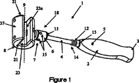
図1は、インプラントの挿入、引出し、抽出、取出し、および/または、位置変更に使用する器具1の一例示実施形態を示すものである。しかしながら、当業者ならば、本発明の要素についてなし得る多くの変更および置換を認識できることを理解すべきである。器具1は、オペレータが、インプラントを骨内に挿入し、骨から引出しまたは取出し、および/または、骨内で位置決め、または、位置変更するのに使用できる。例えば、器具1は、骨髄内ロッドまたは爪を、骨の骨髄管内に挿入し、または、ロッドの引出し、および、取出しを行うのに使用できる。図1に示すように、例示器具1は、ハンドル2と、シャフト4と、ロッキング機構(ロッキング部材6を含む)と、シャフト4にピボット回転可能なように連結された衝撃付与体すなわちヘッド8とで構成できる。
FIG. 1 shows an exemplary embodiment of an instrument 1 for use in insertion, withdrawal, extraction, removal, and / or repositioning of an implant. However, it should be understood by those skilled in the art that many changes and substitutions may be made to the elements of the invention. The instrument 1 can be used by an operator to insert an implant into a bone, withdraw or remove it from the bone, and / or to position or reposition within the bone. For example, the instrument 1 can be used to insert an intramedullary rod or nail into the bone marrow canal of a bone or to withdraw and remove a rod. As shown in FIG. 1, an exemplary instrument 1 includes a handle 2, a shaft 4, a locking mechanism (including a locking member 6), and an impact applicator or
ハンドル2は、オペレータが使用中に器具1を掴みかつ保持することを可能にする。ハンドル2は、オペレータが使用できる人間工学的な輪郭を有するのが好ましく、グリップ性を高める表面、材料、および/または、突起部を設けることができる。オペレータは、ハンドル2の代わりにシャフト4を掴むことができるため、器具1の機能を遂行させる上でハンドル2は必ずしも必要ではないことに留意すべきである。ハンドル2は、プラスチック、ゴム、金属、木材、複合材料(すなわち、少なくとも2つの材料で作られた材料)または他の任意の適当な材料で作ることができる。例えば、ハンドル2は、含浸リネンまたはフェノール樹脂で作ることができる。或いは、ハンドル2は成形ポリマー(例えば、デルリン:Delrin:登録商標)で作ることができる。また、ハンドル2にはコア材料を設け、これを他の材料で包囲することもできる。例えば、アルミニウムコアをシリコンジャケットで包囲することができる。ハンドル2を作るのに使用される材料の決定に際し、種々のファクタを考慮に入れることができ、これらのファクタとして、殺菌および洗浄(例えば、オートクレーブすなわち病院での殺菌に使用される洗浄製品を用いて行う)に耐え得る能力、フィーリング(例えば、オペレータの手に柔軟な感触を与える成形材料)、重量、耐久性(例えば、衝撃荷重に耐える能力、落下に耐える能力)、汚れ(例えば、血液、または手術または器具1の洗浄に使用される物質)に耐える能力、耐熱性、および特に、手術中に一般的に使用されるラテックス手袋によるハンドルのグリップ性がある。ここに列記しない他のファクタも含まれる。 The handle 2 allows the operator to grasp and hold the instrument 1 during use. The handle 2 preferably has an ergonomic contour that can be used by the operator, and can be provided with surfaces, materials, and / or protrusions that enhance grip. It should be noted that the handle 2 is not necessarily required to perform the function of the instrument 1 because the operator can grip the shaft 4 instead of the handle 2. The handle 2 can be made of plastic, rubber, metal, wood, composite material (ie a material made of at least two materials) or any other suitable material. For example, the handle 2 can be made of impregnated linen or phenolic resin. Alternatively, the handle 2 can be made of a molded polymer (e.g., Delrin). Further, the handle 2 can be provided with a core material and surrounded by other materials. For example, an aluminum core can be surrounded by a silicon jacket. In determining the material used to make the handle 2, various factors can be taken into account, including sterilization and cleaning (eg, using autoclaving or cleaning products used in hospital sterilization). Ability to withstand, feel (eg, molding materials that give the operator a soft feel), weight, durability (eg, ability to withstand impact loads, ability to withstand drops), dirt (eg, blood) Or the material used for surgery or cleaning of the instrument 1), heat resistance, and in particular the handle grip of latex gloves commonly used during surgery. Other factors not listed here are also included.
ハンドル2は任意の形状またはサイズにすることができる。例えば、ハンドル2は、手の輪郭にフィットする形状(すなわち、人間工学的に優れた形状)にするのが望ましい。また、ハンドル2の端部3は大きくして、使用中にハンドル2がオペレータの手からスリップすることを防止できる。また、オペレータによるハンドル2のグリッピングを向上させるため、ハンドル2には、その少なくとも一部をカバーするグリップ(図示せず)を設けることができる。
The handle 2 can be any shape or size. For example, it is desirable that the handle 2 has a shape that fits the contour of the hand (that is, an ergonomic shape). Further, the
グリップは、ハンドル2と同じ材料で作ることができる。ハンドル2の材料の選択に使用されるファクタは、グリップ用材料の選択にも適用できる。グリップはハンドル2とは別体ピースとして形成でき、例えばグリップはハンドル内への挿入体(図示せず)として配置できる。また、グリップは、オーバーモールド(例えばハンドル2上への材料のモールディング)により形成できる。ゴムにより作られたグリップを使用することもできる。或いは、グリップはハンドル2と一体にすなわちモノリシックに形成できる(すなわち、ハンドルとグリップとをワンピース材料で作ることができる)。このような形態では、ハンドル2のグリップ部分を粗面化できる。 The grip can be made of the same material as the handle 2. The factors used to select the material for the handle 2 can also be applied to the selection of the grip material. The grip can be formed as a separate piece from the handle 2, for example, the grip can be arranged as an insert (not shown) into the handle. The grip can be formed by overmolding (for example, molding of material on the handle 2). A grip made of rubber can also be used. Alternatively, the grip can be formed integrally or monolithically with the handle 2 (ie the handle and the grip can be made of one piece material). In such a form, the grip part of the handle 2 can be roughened.
シャフト4は、ハンドル2に取付けることもできるし、ハンドル2と一体ピースとして形成することもできる。シャフト4は、例えばステンレス鋼のような硬質材料で作ることができる。しかしながら、シャフト4は任意の適当な材料で作ることができる。シャフト4の材料の決定に際し、例えば殺菌および洗浄に耐え得る能力、重量、汚れに抵抗する能力、および熱処理可能性を含む種々のファクタを使用できる。ここに列記しない他のファクタを含めることもできる。ステンレス鋼のシャフト4の直径は、約5mmから約20mmであり、好ましくは約6mmから約15mmであり、最も好ましくは約7mmから約10mmにすることができる。シャフト4の直径は、使用される材料に基いて定められ、器具1の反復使用によってもシャフト4が曲がったり破断しない充分な強度を有する限り、任意の直径にすることができる。また、ハンドル2からヘッド8まで測定したシャフトの長さは、約20mmから約150mmであり、好ましくは約50mmから約140mmであり、最も好ましくは約100mmから約130mmにすることができる。数ある中で、シャフト4の長さは、オペレータが器具1を適正に揺動することを可能にし、かつハンマー衝撃を付与するための適正なてこ比および運動量を確保するための1つのファクタである。また、シャフト4は、図1に示すように真直にできるが、オペレータがインプラントに衝撃を付与することを可能にしかつロッキング機構7の適正機能を確保できる他の任意の形状(例えば、S型、L型または湾曲型)を考えることができる。
The shaft 4 can be attached to the handle 2 or can be formed as an integral piece with the handle 2. The shaft 4 can be made of a hard material such as stainless steel. However, the shaft 4 can be made of any suitable material. In determining the material of the shaft 4, various factors can be used including, for example, ability to withstand sterilization and cleaning, weight, ability to resist soiling, and heat treatability. Other factors not listed here can also be included. The diameter of the stainless steel shaft 4 is about 5 mm to about 20 mm, preferably about 6 mm to about 15 mm, and most preferably about 7 mm to about 10 mm. The diameter of the shaft 4 is determined based on the material to be used, and can be any diameter as long as the shaft 4 has sufficient strength so that the shaft 4 is not bent or broken even by repeated use of the instrument 1. Also, the length of the shaft measured from the handle 2 to the
シャフト4はハンドル2に当接してもよいし、ハンドル2の全長または一部の長さに亘って延びるように構成することもできる。シャフト4は、摩擦嵌め、溶接、化学的、または、分子接合、または、接着を含む多くの方法でハンドル2に取付けることができる。他の実施形態では、シャフト4に、ハンドル2の雌ねじ(図示せず)と、ねじ結合する雄ねじ(図示せず)を設けることもできる。他の実施形態では、ハンドル2とシャフト4とを互いにロックしてシャフト4を取付けるためのピン、ねじ、止めねじ、ロッド、バーまたは他の保持手段を受入れる開口5を設けることができる。 The shaft 4 may abut against the handle 2, and may be configured to extend over the entire length or a part of the handle 2. The shaft 4 can be attached to the handle 2 in a number of ways including friction fit, welding, chemical or molecular bonding or gluing. In another embodiment, the shaft 4 may be provided with an internal thread (not shown) of the handle 2 and an external thread (not shown) for screw connection. In other embodiments, an opening 5 may be provided for receiving a pin, screw, set screw, rod, bar or other retaining means for locking the handle 2 and the shaft 4 to each other and mounting the shaft 4.
シャフト4にはヘッド8が連結される。ヘッド8は、シャフト4に対してピボット回転可能に、および/または、回転可能に連結されるのが好ましい。一実施形態では、図2に示すように、シャフト4の遠位端18を平坦化するか、小径化して、ここに貫通孔19を設けることができる。小型化されたシャフト部分4は、ヘッド8に形成された開口領域8a(図4)内に挿入できる。ピン19aは、シャフト4がピン19aの回りでピボット回転でき、または、回転できるように、孔19に通して配置できる。ピン19aは、例えば、力嵌めおよび圧力嵌め、溶接、化学的接合、または、分子接合、またはヘッド8の受入れ部分(単一または複数)(図示せず)内への接着によりヘッド8に対して固定できる。或いは、ピン19aはシャフト4に固定することもできる(または、シャフト4に、該シャフト4の反対側から延びる突出部(図示せず)を設けることもできる)。ピンまたは突出部は、シャフト4に対してヘッド8がピボット回転または回転できるようにヘッド8の受入れ部分(単一または複数)(図示せず)内に配置できる。この態様では、ヘッド8がシャフト4の回りでピボット回転できる。
A
開口領域8aは、必ずしも必要でないことを理解すべきである。例えば、ヘッド8には、該ヘッド8の外面37から延びる延長部8b(図4D)(1つ以上の延長部8bを使用できる)を設けることができる。延長部8bには、ピン19aを受入れる孔8cを設けることができる。シャフト4の孔19は、延長部8bの孔8cと整合される。ピン19aは、延長部8bの孔8cおよびシャフト4の孔19に挿通される。このような構成では、シャフト4が揺動すなわちピボット回転できる角度20(以下、「ピボット回転角」と呼ぶ)は、ヘッド8に接触するシャフト4により制限される。
It should be understood that the open area 8a is not necessarily required. For example, the
シャフト4およびヘッド8は、ヘッド8が約360°のピボット回転角20を有するように構成できる(例えば、シャフト4はヘッド8の側面に取付けられる場合(図3))が、より好ましいピボット回転角は約30°から約270°、更に好ましくは約30°から約180°、最も好ましくは約30°から約90°である。ヘッド8に対してシャフト4がピボット回転する角度20は、ヘッド8の開口領域8内でのシャフト4のクリアランスに基いて定まる。ピボット回転角20は、器具1の人間工学的揺動ができる角度であることが好ましい。適当なピボット回転角20の決定に寄与する幾つかのファクタとして、シャフトおよびハンドルの長さと、インプラントの挿入に必要なエネルギを発生させるのに要するスロー(throw)の大きさとがある。
The shaft 4 and
他の実施形態では、シャフト4は、その遠位端18にボール(図示せず)を有し、ヘッド8は、シャフト4のボールを受入れるソケット(図示せず)を有する。或いは、シャフト4およびヘッド8は、ヘッド8がシャフト4の回りで回転できるようにスイベルジョイント(図示せず)により連結できる。ヘッド8がシャフト4に対して少なくとも一方向にまたは少なくとも一軸線の回りでピボット回転でき、および/または、回転できるような態様でシャフト4とヘッド8とを連結する他の任意の手段を使用することもできる。
In other embodiments, the shaft 4 has a ball (not shown) at its
シャフト4とヘッド8とを互いに固定し、これにより、シャフト4の回りでのヘッド8のピボット回転、または、回転運動を防止するロッキング機構7を設けることができる。ロッキング機構には、シャフト4とヘッド8とを互いにロックすべく機能しかつシャフト4およびヘッド8が互いにピボット回転できるようにアンロックすることも可能な任意の機構を設けることができることを理解すべきである。ロッキング機構は、シャフト4と関連させるか、シャフト4に取付けることができ、或いはシャフト4に取付けできるように(すなわち、シャフト4に着脱可能に)構成できる。ロッキング機構は、単一ピースまたは2つ以上のピースで構成できる。
It is possible to provide a locking mechanism 7 that fixes the shaft 4 and the
図1および図2には、例示のロッキング機構7が示されている。図1および図2のロッキング機構は、シャフト4の回りに配置されたロッキング部材6を有している。ロッキング部材6は、ステンレス鋼等の硬質材料で作ることができるが、他の材料を使用することもできる。シャフト4の材料の決定に使用されるファクタと同じファクタが、ロッキング部材6の材料、形状および寸法の決定にも使用できる。シャフト4上に締付けることができる能力およびヘッド8からの衝撃荷重により引起こされる変形に対する抵抗性等の他のファクタも考慮に入れることができる。ロッキング部材6をシャフト4上に締付けることができるようにするには、部材6は、オペレータがその指で(或いは、より詳細に後述するように器具を用いて)、ロッキング部材6をグリップしまたは器具をロッキング部材6に位置決めできる形状および充分なサイズにすべきである。ロッキング部材6は、該部材6がシャフト4とヘッド8とを互いに固定状態に維持する機能を遂行できる限り、任意の形状、サイズまたは厚さにできることを理解すべきである。図示しない一例示実施形態では、ロッキング部材はナットで構成できる。
An exemplary locking mechanism 7 is shown in FIGS. The locking mechanism of FIGS. 1 and 2 has a locking
ハンドル2またはヘッド8と係合するロッキング部材6の部分は、ハンドル2に対するロッキング部材6の保持を補助しまたはシャフト4に対するヘッド8の固定を補助するように構成できることに留意すべきである。例えば、ロッキング部材6には、ハンドル2、および/または、ヘッド8の対応平部分と係合する平部分を設けることができる。ロッキング部材6には、ハンドル2、および/または、ヘッド8の対応粗面化部分または円滑部分と係合する粗面化部分(例えば歯)を設けることもできる。
It should be noted that the portion of the locking
ロッキング部材6には、近位側のねじ山12、または、遠位側のねじ山16と係合する雌ねじ(図示せず)を設けることができる。遠位側のねじ山16は、ヘッド8の近くに配置され、シャフト4の遠位端18でヘッド8に対してロッキング部材6を保持すべく機能する。近位側のねじ山12は、ロッキング部材6がヘッド8とは係合しないように、シャフト4上の位置にロッキング部材6を保持するように機能する。図1において、近位側のねじ山12は、ロッキング部材6がねじ山12と係合すると、ロッキング部材6の部分11が拡大直径部分13、および/または、ハンドル2と係合するように、ハンドル2の近くに配置される。この構成により、ロッキング部材6をシャフト4の近位端14にきつく締付けることができる。
The locking
ロッキング部材6を近位側のねじ山12に係合させるか、拡大部に対してロッキング部材6をきつく締付けることにより、オペレータが挿入・位置決め・取出し器具1を使用するときに、ロッキング部材6は、移動しないように拘束される。より詳しくは、ロッキング部材6は、器具がオペレータにより揺動されるときにシャフト4に沿って移動しない。ロッキング部材6は、該部材6をねじ山12または16上で手で捩ることにより、シャフト4上に締付けられる(すなわち、オペレータはその指および手を使用する)。ロッキング部材6には、グリップ(例えば、図2に示すようなダイヤモンドローレット17)を設けることもできる。該グリップ17は、ロッキング部材6と一体で、ロッキング部材6の一部または全周に形成される粗面、溝または凹部を含む種々の形態にすることができる。他の実施形態では、ロッキング部材6には、別体材料ピースで形成されたグリップを設けることもできる。グリップ17はロッキング部材6の外周面上に配置するか、部材6内にインレーを形成できる。例えば、ロッキング部材6には、ゴムジャケットをオーバーモールディングすることができる。オーバーモールディングされる材料は、円滑表面ではなく、手術前、手術中または手術後にオペレータに良好なグリッピング表面を提供できる任意の材料で形成できる。
When the operator uses the insertion / positioning / removal instrument 1 by engaging the locking
また、ロッキング部材6を更に締付けることができるようにするため、ロッキング部材6の周囲には、任意の形状またはサイズを有する1つ以上の開口15が設けられている。スパナ、ピンレンチ、ロッドまたはバー(図示せず)等の器具を開口15内に配置して、シャフト4上でロッキング部材6を捩るのに使用できる。スパナ、ピンレンチ、ロッド、バーその他の器具は、ねじ山12、16上でロッキング部材6を更に締付けるテコ比をオペレータに与える。ロッキング部材6は手のみで締付けることができる。或いは、手で締付けるのではなく、全締付け段階をスパナ、ピンレンチ、ロッド、バーその他の器具(図示せず)等の器具を用いて行うか、最初にオペレータがロッキング部材6を手で回転させることにより締付け、次に、緊締器具を用いて更に締付けることもできる。スパナ、ピンレンチ、ロッド、バーその他の器具を用いることに加え、または、これらの器具を用いることに代えて、オペレータは、例えば、プライヤ、レンチまたは同等の器具を用いてロッキング部材6の外周面を掴み、該部材6をねじ山12、16上で捩ることができる。また、ロッキング部材6が、ねじ山12、16上で緩むことを防止するため、部材6を貫通するねじ、止めねじ、ボルトまたは他の保持部材を配置して、ねじ山12、16、および/または、シャフト4の表面、および/または、これらの中に接触させることができる。
Further, in order to further tighten the locking
他の実施形態では、ねじ山12を、シャフト4の長さに沿う任意の位置に配置できる。ロッキング部材6をシャフト4に対してきつくロックするため、ねじ山12の一部を変形させておき、および/または、拡大部13をねじ山14に隣接して配置することができる。更に別の実施形態では、シャフト4に、ねじ山部分を1つのみ設けることができる。このねじ山部分は、ロッキング部材6が、ヘッド8に隣接する位置から、部材6がヘッド8から離脱する位置まで移動できるのに充分なだけシャフト4をカバーするのが好ましい。更に別の実施形態では、シャフト4の全体に亘ってねじ山を設けることができる。他の実施形態では、シャフト4の遠位端18での小径部分から近位端14での大径部分までシャフト4にテーパを付すか、拡大部を設けることができる。ロッキング部材6は、テーパ状部分または拡大部上に強く嵌合させることにより、ヘッド8から充分な距離を隔てた位置でシャフト4上に保持でき、これにより、ヘッド8はシャフト4の回りでピボット回転できる。また、任意の実施形態では、ロッキング部材6は、その離脱位置においてシャフト4に沿って移動できるようにする(すなわち、シャフト4にロックされないようにする)か、ヘッド8から離脱されたときにシャフト4から完全に取外されるように設計できる。また、ロッキング機構7には、ねじ山を全く設けないでおくこともできる。
In other embodiments, the
他の実施形態では、ピン、ねじ、止めねじ、ボルトその他の保持手段を、ロッキング部材6を貫通させ、更にシャフト4内にまたはシャフト4を貫通するように構成できる。ピン、ねじ、止めねじ、ボルトその他の保持手段は、開口15に通すこともできるし、貫通孔を形成する他の開口を設けることもできる。これらの貫通孔には、ピン、ねじ、止めねじ、ボルトその他の保持手段の対応ねじ山と係合できるねじ山を設けることができる。この構成は、ロッキング部材6を、シャフト4の長さに沿う任意の位置でシャフト4上に保持するのに使用できる。
In other embodiments, pins, screws, set screws, bolts and other retaining means can be configured to penetrate the locking
更に別の実施形態では、ロッキング機構にバヨネットフィッティングを組込むことができる。例えば、シャフト4の周囲に1つ以上の突出部(図示せず)を設けることができる。突出部(単一または複数)は、単一プロングでもよいし、シャフト4の一部または全長に亘って配置してもよい。この実施形態のロッキング部材6は、突出部(単一または複数)を受入れるための、ロッキング部材の全長に沿う内側溝(単一または複数)でもよい。このような形態は、ロッキング部材6が、突出部(単一または複数)と係合するシャフト4上で軸線方向移動はできるが、回転はできないように構成できる。ピン、ねじ、止めねじ、ボルトその他の保持手段を使用して、ヘッド8に対してロッキング部材6を保持するか、シャフト4の長さ方向に沿う任意の位置に保持することができる。或いは、シャフト4の周囲にスプリング(図示せず)を配置して、ロッキング部材6をヘッド8の方向に押し付けることもできる。ロッキング機構として、上記実施形態および特徴の任意の組合せを使用できることに留意すべきである。
In yet another embodiment, a bayonet fitting can be incorporated into the locking mechanism. For example, one or more protrusions (not shown) can be provided around the shaft 4. The protrusion (single or plural) may be a single prong or may be arranged over a part or the entire length of the shaft 4. The locking
他の実施形態では、ロッキング部材6を設けないでおくことができる。このような実施形態では、シャフト4がヘッド8に対してピボット回転しないように、ピン、ねじ、止めねじ、ボルトその他の保持手段を使用できる。当業者ならば、本発明により、シャフト4およびヘッド8を互いに一時的に固定する他の手段を考えることは容易に明らかである。
In other embodiments, the locking
図3に示すように、他の実施形態では、シャフト4をヘッド8の側面に連結できる。シャフト4は、クエスチョンマーク(?)に似た形状であり、ハンドル2を有している。シャフト4とヘッド8との連結は、シャフト4に対してヘッド8がピボット回転でき、および/または、回転運動できるものでなくてはならない。しかしながら、シャフト4は、ヘッド8がシャフト4に対してピボット回転し、および/または、回転し、器具1がインプラントに衝撃を付与し、インプラントの位置変更または骨からの取出しおよび引出しに使用できるように、ヘッド8の外面37(図1)上のどの位置にも連結できることに留意すべきである。
As shown in FIG. 3, in another embodiment, the shaft 4 can be coupled to the side of the
ヘッド8は、該ヘッド8が、インプラントを骨内に挿入し、位置変更しまたは骨から引出す力を伝達するインサータ29(図7)等の一部、および/または、インプラントに衝撃および衝撃を付与すべく機能できる限り任意の形状およびサイズにすることができる。ヘッド8の外面37、好ましくは面21、面21aは、インプラントまたは挿入器具に衝撃および衝撃を付与するのに使用できる。また、ヘッド8の面21、面21aには、ヘッド8より強い材料(例えば、凹み、および/または、変形に対する抵抗性の大きい材料)で作られた材料ピースを取付けることができる。例えば、面21、および/または、面21aにチタンピースを溶接できる。他の実施形態では、インプラントに付与するハンマー衝撃から生じる衝撃力を吸収すべく、面21、面21aに軟質材料を取付けることができる。例えば、面21、および/または、面21aにゴムピースを接合できる。ハンマー衝撃時に他の表面と接触することがあるヘッド8の任意の部分に、別の材料ピースを取付けることができることに留意すべきである。
The
ヘッド8はステンレス鋼で作ることができるが、他の材料を使用することもできる。ヘッド8の材料を決定するのに、シャフト4または部材6の材料の選択に関して前述した種々のファクタの全てを使用できる。また、ヘッド8の長さは、約30mmから約150mmの間であり、好ましくは約40mmから約100mmの間であり、最も好ましくは約50mmから約75mmの間に定めることができる。また、ヘッド8の直径は、約30mmから約100mmの間であり、好ましくは約35mmから約75mmの間であり、最も好ましくは約38mmから約60mmの間に定めることができる。ヘッド8の直径を決定するときは、インプラントの挿入に必要なエネルギを発生させるのに要するヘッドの重量および/または質量を含む種々のファクタを考慮に入れることができる。
The
また、ヘッド8には、チャネル23と、該チャネルと交差するスロット23aとを設けることができる。ヘッド8およびチャネル23は長手方向軸線9を共有するが、ヘッド8およびチャネル23の各々は、互いに平行であるか、任意の角度で傾斜した別々の軸線を有する。スロット23aはチャネル23およびヘッド8の外面37に連通しており、これにより、図7に示す長手方向部材30aのようなガイドをチャネル23内に挿入する通路を形成している。図1に示すように、スロット23aはヘッド8の長さ方向に形成され、かつその全長に沿ってチャネル23と交差している。図7に示すように、チャネル23は、インサータ29のようなインプラントインサータのガイド30を受入れるように構成されている。チャネル23は、ガイド30をこの中に挿入できる限り任意のサイズにすることができ、またチャネル23はガイド30に沿ってヘッド8を往復運動させることができる。例えば、チャネル23の直径すなわち厚さは、約5mmから約35mmの間であり、好ましくは約6mmから約24mmの間であり、最も好ましくは約7mmから約20mmの間に定めることができる。ガイド30がチャネル23内に配置されたとき、チャネル23は、ガイド30をチャネル23内に保持する機構すなわち手段を形成するのが望ましい。図4は、例示の保持部材としてボールプランジャ25を備えたヘッド8の断面図である。
The
ヘッド8には、1つ以上のボールプランジャ25を設けることができる。ボールプランジャ25には、スプリング27およびボールベアリング31を収容するハウジング28を設けることができる。ハウジング28は、ボールベアリング31がハウジング28から落下することを防止すると同時に、ボールベアリング31の一部がハウジング28からチャネル23内に突出するように構成されている。ボールベアリング31は、スプリング27に固定することによってハウジング28内に保持することもできる。ボールベアリング31は、例えばロッド30をチャネル23内に挿入することによりボールベアリングに加えられる力に応答して、ハウジング内で上下に移動できる。ボールプランジャ25は、ヘッド8の孔33(または開口)内に配置される。プランジャ25には、孔33の内周面に形成された雌ねじ(図示せず)と係合する雄ねじ(図示せず)を設け、プランジャ25を所定位置に保持することができる。或いは、プランジャ25は、力嵌め、溶接、化学的接合または分子接合または接着を含む種々の方法でヘッド8に連結できる。チャネル23またはスロット23a内のプランジャ25の位置(すなわち、プランジャ25がチャネル23またはスロット23a内に突出する度合い)は、使用されるガイドおよびチャネル23のサイズに基いて定められる。
The
ボールベアリング31は、例えば球形、傾斜三角形(図4A)、半球形(図4B)、真直側面三角形(図4C)等の任意の形状にすることができる。ボールベアリング31の形状は、ガイド30から器具1を取出すべく所定の力を加えたときに、ガイド30をチャネル23内に(またはチャネル23から)移動させることができるものでなくてはならない。ガイド30が保持部材に通されたとき、ヘッド8は、ガイド30に沿って移動できることが好ましい。他の実施形態では、保持部材は、チャネル23の一部の長さまたは全長に亘って配置できる。他の実施形態では、保持部材は、例えば、ヘッド8および/またはチャネル23内またはこれらの上に配置できるねじ、止めねじ、ピン、バーまたはロッドで構成できる。ガイド30がチャネル23に出入り移動でき、かつ、ヘッド8がガイド30に沿って移動できるものである限り、当業者ならば、チャネル23内にガイド30を保持する他の機構すなわち手段を考え得ることは理解されよう。ヘッド8はまた、保持部材を調節できるように構成することもできる(すなわち、保持部材はチャネル23内のどこにでも配置でき、保持部材は種々の度合いでチャネル23内に突出するように調節できる)。
The
図4Eには、フィンガ42を備えた他の保持部材コンポーネント40が示されている。当業者ならば、コンポーネント40は、これ自体で、または例えばボールプランジャ25等の他の保持部材と組合せて使用できることが理解されよう。コンポーネント40の一部(図示せず)は、シャフト4に対して作動可能に連結できる。ピン、ねじ、止めねじ、バーまたはロッド44は、ヘッド8の開口およびコンポーネント40の開口(図示せず)を通して、ヘッド8内の受入れ部分(図示せず)内に配置できる。当業者ならば、コンポーネント40がヘッド8内で回転またはピボット回転(シャフトが回転またはピボット回転するときのスロット48内での回転またはピボット回転を含む)できるようにする任意の構造を考え得ることが理解されよう。或いは、コンポーネント40は、フィンガ42がシャフト4とは独立的に移動するように設計できる。コンポーネント40は、フィンガ42がチャネル23内に(部分的または全体的に)伸長でき、および/または、チャネル23から出て(部分的または全体的に)スロット48内に引っ込められるように構成できる。例えば、コンポーネント40は、スロット48を通って直線的に上下移動し、チャネル23に出入りするように設計できる。しかしながら、この上下移動形態の場合でも、コンポーネント40はシャフト4に取付けることができる。
In FIG. 4E, another retaining
ヘッド8を、長手方向部材30a等のガイド30上に配置するため、コンポーネント40は、(単独で、シャフト4に沿ってコンポーネント40を回転およびピボット回転させることにより、またはコンポーネント40をシャフト4と一緒に直線的に上下移動させることにより)回転し、ピボット回転しまたはスロット48内に直線的に下降できる。フィンガ42は、該フィンガ42のいかなる部分もチャネル23内に入らないように、スロット48内に全部を配置できる。しかしながら、フィンガ42は、ガイド30がチャネル23に入ることができるようにする必要があるときのみ、スロット48内に位置決めされればよい、ヘッド8が長手方向部材30a等のガイド30上に配置されかつ該ガイド30上で往復運動されるとき、コンポーネント40は、ヘッド8がガイド30から離脱してしまう度合いまでには回転またはピボット回転しないことが望まれる。
In order to place the
また、ヘッド8には、オペレータが、プランジャ25等の保持部材の位置を調節できるように、多数の孔(すなわち開口)33をヘッド8に設けることができる。また、ヘッド8およびプランジャ25は、ボールベアリング31がチャネル23内に突出する度合いをオペレータが調節できるように構成できる。長手方向部材30a等のガイド30をチャネル23内に一時的に保持するのに使用できる任意の機構が考えられることに留意すべきである。
The
ここで図5を参照すると、ヘッド8の他の実施形態が示されている。この実施形態では、インサータ29のようなインプラントインサータの長手方向部材30aのようなガイド30は、チャネル23内に捩じ込まれる。ヘッド8の外面37の間にはスロット35が配置されており、該スロット35はチャネル23に連通し、かつ、該チャネル23と交差している。スロット35の軸線は、チャネル23の長手方向軸線9に対して横方向、より好ましくは長手方向軸線9に対して90°の角度に配向されている。約0°から約180°の間の任意の角度も考えられることを理解すべきである。また、チャネル23には、チャネル23およびヘッド8の外面37に連通して、ガイド30をチャネル23内に挿入する通路を形成する対向サイドチャネル39を設けることができる。ヘッド8のスロット35はガイド30上に配置され、次にサイドチャネル39を通してチャネル23内に位置決めされ、これによりガイド30の長手方向軸線がチャネル23の長手方向軸線9と整合される。他の実施形態では、ヘッド8の外面からチャネル23へと延びるヘリカルスロットを設けることができる。
Referring now to FIG. 5, another embodiment of the
図6には、ヘッド8の他の実施形態が示されている。この実施形態では、ヘリカルスロット50が設けられている。ヘッド8は、インサータ29のようなインプラントインサータの長手方向部材30aのようなガイド30上に捩じ込まれ、回転されまたは捩られる。
ヘリカルスロット50はヘッド8の外面37の間に延びており、かつチャネル23に連通しかつ該チャネル23と交差している。ヘリカルスロット50はまた、外面52の前面54および後面56と交差する。ヘッド4のヘリカルスロット50がガイド30上で前進されると、ヘッド4はチャネル23内に捩じ込まれ、捩られまたは回転され、これにより、ガイド30の長手方向軸線がチャネル23の長手方向軸線9と整合される。
FIG. 6 shows another embodiment of the
The
図7および図8は、骨髄内ロッド24のようなインプラントを、骨26内に挿入し、骨26から引出し、取出し、位置決めし、または、位置変更するための、インサータ29のようなインプラントインサータ器具を備えた器具1の使用方法を示すものである。図7は、ロッド24のようなインプラントを骨26内に挿入する器具1の使用方法を示す。図7に示すような器具1を使用するには、ヘッド8をシャフト4に対して固定し、ヘッド8がシャフト4の回りでピボット回転せず、または、回転できないようにするのが好ましい。ヘッド8をシャフト4に対して固定するのに、ロッキング部材6のようなロッキング機構7を使用できる。ヘッド8は、遠位端18のねじ山16(図2)上にロッキング部材6を捩じ込むことにより固定される。ヘッド8がシャフト4上でピボット回転し、および/または、回転しない限り、シャフト4に対してヘッド8を固定するのに任意のロッキング機構を使用できることを理解すべきである。この態様では、ヘッド8は「固定位置」にある。
7 and 8 show an implant inserter instrument, such as
固定位置では、ヘッド8は、骨髄内ロッド24のようなインプラントを骨26内に打込むのに使用できる。ロッド24を骨26内に打込む補助をするため、インサータ29のようなインプラントインサータを設けることができる。しかしながら、器具1は、インプラントを直接打込むのに使用できる。インサータ29はロッド24に取付けられかつきのこ型ヘッド部分28および照準アーム22を有している。使用に際し、オペレータおよび/またはアシスタントは手で照準アーム22を保持し、かつオペレータおよび/またはアシスタントは、器具1のヘッド8により部分28に衝撃を付与する。器具1を矢印32aで示す方向に揺動させかつ部分28に衝撃を付与することにより、ロッド24が骨26内に打込まれる。器具1が図7に示すインサータ29を用いて(またはいかなるインサータをも用いることなく)使用されるとき、ヘッド8はシャフト4に対して固定するのが好ましいことを理解すべきである。また、ヘッド8が、図6に示すインサータ29を用いて(またはいかなるインサータも使用することなく)使用されるとき、ヘッド8はシャフト4に対してピボット回転できることことも考えられる。
In the fixed position, the
変形例として、図8は、ロッド24のようなインプラントを骨26に挿入し、骨26から引出し、取出し、位置決めしまたは位置変更する器具1の使用方法を示すものである。図8に示すように器具1を使用するには、ヘッド8は、シャフト4に対してピボット回転できることが好ましい。これを達成するには、ロッキング部材6を、ねじ山16から緩めてロッキング部材6をシャフト4の近位端14の方向に移動させることにより、ロッキング部材6のようなロッキング機構7がヘッド8から離脱される。ロッキング部材6は、該部材6を、近位端14のねじ山12(図1)に捩じ込むことにより器具1の揺動中に移動できなくなり、シャフト4上に静止される。ロッキング部材6は、今や、ヘッド8から充分な距離を隔てており、ヘッド8を、シャフト4に対して矢印20(図2)で示す方向にピボット回転させることができる。前述のように、シャフト4とヘッド8とが如何に取付けられるかによって、ヘッド8がシャフト4の回りで回転できるか否かが定められる。この形態では、ヘッド6は「トグル位置」にあり、スラップハンマーすなわちスライドハンマーと同様に機能する。
As a variant, FIG. 8 shows the use of the instrument 1 for inserting an implant, such as a
トグル位置では、ヘッド8はインサータ29のようなインプラントインサータ器具に使用され、ロッド24のようなインプラントを、骨26内に挿入し、および/または、骨26から取出すハンマー衝撃を、インプラントに付与する。インサータ29はロッド24に取付けられかつ照準アーム22と、遠位側のきのこ型ヘッド部分28と、ガイド30(例えば、長手方向部材30a)と、近位側きのこ型ヘッド部分34とを有している。当業者ならば、ガイド30は、ヘッド8が該ガイド30上に嵌合され、かつ、該ガイド30に沿って移動できる限り、円形、楕円形、正方形、長方形または他の多角形を含む任意の形状にできることは明らかであろう。器具1のヘッド8は、ガイド30がチャネル23に入るまでスロット23aをガイド30上で移動させることにより、ガイド30上に配置される。ガイド30は、前述のような保持部材を用いて、チャネル23内に保持される。ロッド24を骨26内に挿入するには、オペレータおよび/またはアシスタントはアーム22を手で持ち、ガイド30上でヘッド8を矢印32で示す方向に反復往復運動させて、器具1のヘッド8により部分28を打ち付ける。これにより、ロッド24は骨26内に打込まれる。骨26からロッド24を引出し、または、取出し、或いは骨断片を整復(すなわち、2つの骨断片を引っ張って一体化)させ、または骨内でロッド24を位置変更するためには、オペレータおよび/またはアシスタントは、ガイド30上でヘッド8を矢印32で示す方向に反復往復運動させ、器具1のヘッド8により部分34に衝撃を付与する。
In the toggle position, the
図5の器具は、上記と同じ往復運動を用いて使用される。また、前述のように、ロッキング部材6のようなロッキング機構を用いてシャフト4に対してヘッド8を固定し、かつヘッド8がシャフト4に対してトグル作用をするように配置できる。ガイド30上へのヘッド8の配置方法のみが異なっている。スロット35は、ガイド30がチャネル23と交差するまで、ガイド30上に配置される。この時点では、ガイド30の長手方向軸線は、チャネル23の長手方向軸線に対して或る角度で傾斜している。次に、ガイド30が対向サイドチャネル39を通ってチャネル23内に入るように、ヘッド8が回転される。この時点では、ガイド30の長手方向軸線がチャネル23の長手方向軸線と整合する。図5に示すヘッド8の実施形態においてガイド30を一時的に保持するのに、図1および図2のヘッド8内にガイド30を一時的に保持するのに使用されるのと同じ機構および構造(例えばプランジャ25)を使用できる。図6に示す更に別の実施形態では、長手方向部材30aのようなガイド30がヘリカルスロット50内に配置される。ヘリカルスロット50がガイド30上で前進されると、ヘッド8が捩じ込まれ、回転しまたは捩られて、ガイド30がチャネル23内に配置される。この時点で、ガイド30の長手方向軸線が、チャネル23の長手方向軸線9と整合する。
The instrument of FIG. 5 is used with the same reciprocating motion as described above. Further, as described above, the
以上、本発明の好ましい実施形態を説明しかつ図示したが、特許請求の範囲に記載された本発明の精神および範囲を逸脱することなく種々の変更および置換を行い得ることを理解すべきである。特に、当業者ならば、本発明の精神または本質的特徴から逸脱することなく、他の要素、材料およびコンポーネンツを用いて、本発明を他の特定形態、構成、比率で具現できることは明白であろう。当業者ならば、本発明は、本発明の原理から逸脱することなく、特定環境および作業条件に特に適合した多くの構造変更、構成、比率、材料およびコンポーネンツを使用できることは明白であろう。従って、本明細書で説明した実施形態はあらゆる点で例示であって限定的なものではなく、本発明の範囲は特許請求の範囲の記載により定められ、本明細書での説明に限定されるものではない。 While the preferred embodiment of the invention has been described and illustrated, it is to be understood that various changes and substitutions can be made without departing from the spirit and scope of the invention as set forth in the appended claims. . In particular, it will be apparent to those skilled in the art that the present invention may be embodied in other specific forms, configurations, and ratios using other elements, materials, and components without departing from the spirit or essential characteristics of the invention. Let's go. It will be apparent to those skilled in the art that the present invention can employ many structural modifications, configurations, ratios, materials and components that are particularly adapted to particular environments and operating conditions without departing from the principles of the present invention. Accordingly, the embodiments described herein are illustrative and not restrictive in every respect, and the scope of the present invention is defined by the description of the scope of claims and is limited to the description herein. It is not a thing.
1 骨インプラントに使用する器具
2 ハンドル
4 シャフト
6 ロッキング部材
8 衝撃付与体(ヘッド)
22 照準アーム
23 チャネル
23a スロット
30 ガイド
35 スロット
39 サイドチャネル
50 ヘリカルスロット
DESCRIPTION OF SYMBOLS 1 Instrument used for bone implant 2 Handle 4
22 Aiming
Claims (27)
或る長さを有し、第一長手方向軸線を有する衝撃付与体と、
近位端、遠位端、及び第二長手方向軸線を備えたシャフトを有し、シャフトの遠位端は、衝撃付与体に対して作動可能に連結され、シャフトは、第二長手方向軸線が衝撃付与体の第一長手方向軸線に対して回転し、作動位置において衝撃付与体がシャフトに対して回転できるピボット回転角を作り出すように、衝撃付与体に対してピボット回転できるようになっており、
少なくとも2つの作動位置を備えたロッキング機構を更に有し、前記ロッキング機構は、第一位置ではシャフトが衝撃付与体に対してピボット回転することを許容し、第二位置ではシャフトが衝撃付与体に対してピボット回転することを防止するようになっており、
衝撃付与体は、骨にインプラントされるインプラントに連結されたインプラントガイドを摺動可能に受け入れられる寸法及び形状を有するチャンネルを備え、チャンネルは、第二位置においてシャフトの第二長手方向軸線とほぼ直交する方向に、衝撃付与体の全長にわたって延び、これにより衝撃付与体がインプラントガイドに沿って摺動し、インプラントガイドの当接面に当たってインプラントを骨内に押し進めるようになっている、ことを特徴とする器具。 A device for implanting a bone implant,
An impact applicator having a length and having a first longitudinal axis ;
The shaft has a proximal end , a distal end , and a second longitudinal axis , the distal end of the shaft is operably connected to the impactor, and the shaft has a second longitudinal axis. It rotates about the first longitudinal axis of the impact applicator and is pivotable with respect to the impact applicator so as to create a pivot angle that allows the impact applicator to rotate relative to the shaft in the operating position. ,
And a locking mechanism having at least two operating positions, the locking mechanism allowing the shaft to pivot relative to the impact imparting body in the first position and the shaft to the impact imparting body in the second position. It is adapted to prevent the pivoting against,
The impactor includes a channel having a size and shape that is slidably received in an implant guide coupled to an implant that is implanted in the bone, the channel being substantially orthogonal to the second longitudinal axis of the shaft in a second position. The impact applicator extends over the entire length of the impact applicator in such a manner that the impact applicator slides along the implant guide and abuts against the abutment surface of the implant guide to push the implant into the bone. Instruments to do.
或る長さを有し、第一長手方向軸線及び外面を備えたヘッドを有し、該ヘッドは、骨に挿入されるインプラントに連結されたインプラントガイドを摺動可能に受け入れられるような寸法及び形状を有するチャンネルを備え、該チャンネルは、ヘッドがインプラントガイドに沿って摺動してインプラントガイドの当接面に接触し、インプラントを骨内に押し進めることができるように、第一軸線に沿ってヘッドの全長にわたって延び、ヘッドは、さらにチャンネル及びヘッドの外面と交差するスロットを備え、
近位端、遠位端、及び第二長手方向軸線を備えたシャフトを有し、シャフトの遠位端は、ヘッドに対して作動できるように連結され、
少なくとも2つの状態を備えたロッキング機構を更に有し、前記ロッキング機構は、第二長手方向軸線がヘッドの第一長手方向軸線に対して回転し、第一作動位置において衝撃付与体がシャフトに対して回転できるピボット回転角を作り出すように、シャフトがヘッドに対してピボット回転することを許容する第一状態と、第二作動位置においてシャフトがヘッドに対してピボット回転することを防止するようになった第二状態とを備え、
ヘッドのチャンネルは、第二状態においてシャフトの第二長手方向軸線とほぼ直交する、ことを特徴とする器具。 A device for implanting a bone implant,
A head having a length and having a first longitudinal axis and an outer surface, the head being dimensioned to slidably receive an implant guide coupled to an implant inserted into the bone; A channel having a shape, the channel along the first axis so that the head can slide along the implant guide to contact the abutment surface of the implant guide and push the implant into the bone Extending over the entire length of the head, the head further comprising a slot intersecting the channel and the outer surface of the head;
A shaft having a proximal end , a distal end , and a second longitudinal axis , the distal end of the shaft being operably connected to the head;
A locking mechanism having at least two states, wherein the locking mechanism rotates the second longitudinal axis relative to the first longitudinal axis of the head, and the impact applier is relative to the shaft in the first operating position; to create a pivot angle which is rotatable Te, shaft so as to prevent the first state that allows pivoting relative to the head, that the shaft in the second operating position pivots relative to the head With a second state,
A device characterized in that the channel of the head is substantially perpendicular to the second longitudinal axis of the shaft in the second state .
或る長さ、及び第一長手方向軸線と、チャンネルとを有するヘッドを備え、チャンネルは、骨に挿入されるインプラントに連結されたインプラントガイドを摺動可能に受け入れるような寸法及び形状を有し、チャンネルは、ヘッドがインプラントガイドに沿って摺動してインプラントガイドの当接面に接触し、インプラントを骨内に推し進められるようにヘッドの全長にわたって延び、
少なくともねじ山部分、第二長手方向軸線、近位端および遠位端を備えたシャフトとを有し、前記シャフトの遠位端は、第二長手方向軸線がヘッドの第一長手方向軸線に対して回転して作動位置においてヘッドがシャフトに対して回転できるピボット回転角を作り出すように、シャフトに対するヘッドのピボット回転を許容するようにヘッドに対して作動可能に連結されており、
雌ねじ部分を備えたロッキング部材を更に有し、ロッキング部材は、シャフトがヘッドに対してピボット回転することをロッキング部材が許容する第一位置から、ロッキング部材のねじ山部分がシャフトのねじ山部分と係合して、ヘッドと接触するようにロッキング部材を位置決めし、かつ、ヘッドに対してシャフトがピボット回転することを防止する第二位置まで移動できるようになっており、
ヘッドのチャンネルは、第二位置において第二長手方向軸線とほぼ直交するようになっている、ことを特徴とする器具。A device for impacting, positioning and removing a bone implant,
A head having a length and a first longitudinal axis and a channel , the channel being sized and shaped to slidably receive an implant guide coupled to an implant inserted into the bone. The channel extends over the entire length of the head so that the head slides along the implant guide to contact the abutment surface of the implant guide and drive the implant into the bone;
A shaft having at least a threaded portion, a second longitudinal axis, a proximal end and a distal end, the distal end of the shaft having a second longitudinal axis relative to the first longitudinal axis of the head Operatively connected to the head to allow pivoting of the head relative to the shaft so as to create a pivoting angle that allows the head to rotate relative to the shaft in the operating position .
The locking member further includes an internal thread portion, the locking member from a first position where the locking member allows the shaft to pivot relative to the head, the locking member thread portion from the shaft thread portion. Engaging, positioning the locking member to contact the head, and moving to a second position that prevents the shaft from pivoting relative to the head ;
A device according to claim 1, characterized in that the channel of the head is substantially perpendicular to the second longitudinal axis at the second position .
Applications Claiming Priority (3)
| Application Number | Priority Date | Filing Date | Title |
|---|---|---|---|
| US10/831,569 US20050240197A1 (en) | 2004-04-23 | 2004-04-23 | Device and method for inserting, positioning and removing an implant |
| US10/831,569 | 2004-04-23 | ||
| PCT/US2005/013600 WO2005104968A2 (en) | 2004-04-23 | 2005-04-21 | Device and method for inserting, positioning and removing an implant |
Publications (3)
| Publication Number | Publication Date |
|---|---|
| JP2007533415A JP2007533415A (en) | 2007-11-22 |
| JP2007533415A5 JP2007533415A5 (en) | 2008-06-19 |
| JP5017095B2 true JP5017095B2 (en) | 2012-09-05 |
Family
ID=35137479
Family Applications (1)
| Application Number | Title | Priority Date | Filing Date |
|---|---|---|---|
| JP2007509627A Expired - Fee Related JP5017095B2 (en) | 2004-04-23 | 2005-04-21 | Implant insertion, positioning and removal devices |
Country Status (12)
| Country | Link |
|---|---|
| US (1) | US20050240197A1 (en) |
| EP (1) | EP1742587B1 (en) |
| JP (1) | JP5017095B2 (en) |
| KR (1) | KR101176147B1 (en) |
| CN (2) | CN1976641B (en) |
| AT (1) | ATE515984T1 (en) |
| AU (1) | AU2005237492B2 (en) |
| BR (1) | BRPI0510160A (en) |
| CA (1) | CA2563783C (en) |
| NZ (1) | NZ551306A (en) |
| WO (1) | WO2005104968A2 (en) |
| ZA (1) | ZA200609229B (en) |
Families Citing this family (16)
| Publication number | Priority date | Publication date | Assignee | Title |
|---|---|---|---|---|
| NZ548246A (en) * | 2003-12-08 | 2009-06-26 | Synthes Gmbh | Surgical mallet with a cylindrical head and recess for extraction of Kirschner wires and other segical connectors |
| ES2858515T3 (en) * | 2012-03-30 | 2021-09-30 | Orthodontic Res And Development S L | Procedure for mounting a distalizer |
| EP2838931A1 (en) | 2012-04-17 | 2015-02-25 | Merck Patent GmbH | Cross-linkable and cross-linked polymers, methods for the production thereof, and use thereof |
| US20140276820A1 (en) | 2013-03-15 | 2014-09-18 | Biomet C.V. | External fixation system |
| CN114983546A (en) | 2013-05-13 | 2022-09-02 | 尼奥医疗公司 | Orthopedic implant kit |
| US9770279B2 (en) | 2015-05-18 | 2017-09-26 | Little Engine, LLC | Method and apparatus for extraction of medical implants |
| DE102015007540A1 (en) * | 2015-06-16 | 2016-12-22 | Adalbert Missalla | Surgical instrument set |
| US10485558B1 (en) * | 2015-07-31 | 2019-11-26 | Joshua Cook | Apparatus and method for harvesting bone |
| EP3525692B1 (en) * | 2016-10-14 | 2021-04-21 | Zimmer, Inc. | Multi-use tool |
| CN111405876B (en) * | 2017-07-10 | 2023-05-23 | 塔斯外科公司 | Dual function anchor system |
| EP3651672A4 (en) * | 2017-07-14 | 2021-03-31 | Merit Medical Systems, Inc. | Bone access device holder and methods of use |
| JP7515399B2 (en) | 2018-02-26 | 2024-07-12 | ネオ・メディカル・ソシエテ・アノニム | Cage Holder |
| WO2019169357A1 (en) * | 2018-03-01 | 2019-09-06 | Alden Kris | Prosthetic component extractor |
| CN109247983A (en) * | 2018-09-20 | 2019-01-22 | 史迎春 | A kind of jaw type Multifunctional elastic intramedullary needle fastener driving device |
| CN113194886A (en) | 2018-11-08 | 2021-07-30 | 尼奥医疗公司 | Spinal fusion device hammer |
| WO2021097491A1 (en) * | 2019-11-15 | 2021-05-20 | Paragon 28, Inc. | Instruments, systems, and methods of using |
Family Cites Families (84)
| Publication number | Priority date | Publication date | Assignee | Title |
|---|---|---|---|---|
| US691309A (en) * | 1901-03-16 | 1902-01-14 | Felix S Goldsmith | Prospector's pick or similar tool. |
| US703790A (en) * | 1901-09-26 | 1902-07-01 | Dawson M Humiston | Glazier's hammer. |
| US1822280A (en) * | 1929-06-26 | 1931-09-08 | John F Ervay | Carpenter's hammer |
| US2043442A (en) * | 1935-03-21 | 1936-06-09 | James E Mcneil | Tool holder |
| US2613475A (en) * | 1949-02-04 | 1952-10-14 | Adrien R Mellor | Striking toy |
| US3094021A (en) * | 1960-10-26 | 1963-06-18 | Curtiss Wright Corp | Impact wrench structure for tightening or loosening rod joints |
| US3208450A (en) * | 1962-03-14 | 1965-09-28 | Abelson Louis | Fracture setting tool |
| CH405600A (en) * | 1963-09-26 | 1966-01-15 | Synthes Ag | Intramedullary nail and the appropriate drive-in and extraction tool |
| CH490076A (en) * | 1968-04-25 | 1970-05-15 | Arnold Heinrich Dr Med Huggler | Instrument for use with a joint head prosthesis for the femur |
| US3750500A (en) * | 1971-04-29 | 1973-08-07 | A Peterson | Dowel pin extractor tool |
| US3834393A (en) * | 1973-07-09 | 1974-09-10 | R Goggins | Veterinary surgical tool for enlarging the pelvic girdle of a heifer during parturition |
| US4153053A (en) * | 1977-09-12 | 1979-05-08 | Eleazar Figallo E | Method of reducing malar fractures using a hammer disimpactor |
| AT358715B (en) * | 1978-09-04 | 1980-09-25 | Plansee Metallwerk | BUTCHING AND REJECTING DEVICE FOR BONE MARKING NAIL |
| US4222382A (en) * | 1979-01-26 | 1980-09-16 | Massachusetts Institute Of Technology | Femoral component hip joint prosthesis extractor |
| DE2944710A1 (en) * | 1979-11-06 | 1981-05-07 | Christos Dr. Dimakos | DEVICE FOR REMOVING A BONE CEMENT TUBE IN A REIMPLANTATION OF AN ARTIFICIAL THIGH NECK |
| US4399813A (en) * | 1981-01-22 | 1983-08-23 | Barber Forest C | Apparatus and method for removing a prosthesis embedded in skeletal bone |
| US4399978A (en) * | 1982-02-26 | 1983-08-23 | Moore Charles H | Hand tool with variable inclined head |
| US4462395A (en) * | 1983-03-02 | 1984-07-31 | Johnson Lanny L | Arthroscopic ligamentous and capsular fixation system |
| US4459985A (en) * | 1983-03-04 | 1984-07-17 | Howmedica Inc. | Tibial prosthesis extractor and method for extracting a tibial implant |
| RO89820B1 (en) * | 1985-11-05 | 2002-06-28 | îNTREPRINDEREA INDUSTRIA TEHNICO MEDICALA | Elastic implants for a stable elastic osteorrhaphy of femoral and tibial fractures, respectively, as well as corresponding instrumentation |
| US4924056A (en) * | 1986-08-13 | 1990-05-08 | Bevilacqua Richard M | Dent puller and method of use |
| US4805494A (en) * | 1987-08-24 | 1989-02-21 | Richard Santoro | Articulate hammer |
| US5122146A (en) * | 1988-02-04 | 1992-06-16 | Pfizer Hospital Products Group, Inc. | Apparatus for reducing a fracture |
| US5484437A (en) * | 1988-06-13 | 1996-01-16 | Michelson; Gary K. | Apparatus and method of inserting spinal implants |
| US5156606A (en) * | 1988-10-11 | 1992-10-20 | Zimmer, Inc. | Method and apparatus for removing pre-placed prosthetic joints and preparing for their replacement |
| US4919153A (en) * | 1988-10-11 | 1990-04-24 | Origin Medsystems, Inc. | Method and apparatus for removing pre-placed prosthetic joints and preparing for their replacement |
| US4993410A (en) * | 1989-05-01 | 1991-02-19 | Kimsey Timothy P | Prosthetic removal device |
| US5116335A (en) * | 1989-09-18 | 1992-05-26 | Hannon Gerard T | Intramedullary hybrid nail and instrumentation for installation and removal |
| US5122144A (en) * | 1989-09-26 | 1992-06-16 | Kirschner Medical Corporation | Method and instrumentation for unicompartmental total knee arthroplasty |
| US5152792A (en) * | 1990-02-06 | 1992-10-06 | Zimmer, Inc. | Apparatus and method for gauging and controlling process steps used to remove prosthetic joints |
| US5041120A (en) * | 1990-01-19 | 1991-08-20 | Origin Medsystems, Inc. | Multipart kit and method of using the same to remove cement used to secure prosthetic joints |
| US5122143A (en) * | 1990-04-17 | 1992-06-16 | Origin Medsystems, Inc. | Method and apparatus for extracting a cement mantle from a bone recess |
| US5078718A (en) * | 1990-04-17 | 1992-01-07 | Origin Medsystems, Inc. | Multi-part method and apparatus for removing pre-placed prosthetic joints and preparing for their replacement |
| US5222957A (en) * | 1990-04-17 | 1993-06-29 | Zimmer, Inc. | Method and apparatus for extracting a cement mantle from a bone recess |
| US5190550A (en) * | 1990-08-02 | 1993-03-02 | Exactech, Inc. | Locking surgical tool handle system |
| US5100404A (en) * | 1990-09-04 | 1992-03-31 | Beth Israel Hospital | Intramedullary nailing method and apparatus |
| US5190551A (en) * | 1990-12-14 | 1993-03-02 | Zimmer, Inc. | Controlled apparatus and method for extracting cement mantles from bone recesses |
| US5098437A (en) * | 1991-02-13 | 1992-03-24 | Pfizer Hospital Products Group, Inc. | Acetabular cup positioning insert |
| US5280738A (en) * | 1991-08-20 | 1994-01-25 | Liou Mou Tang | Hammer with an angle-adjustable head |
| US5429640A (en) * | 1992-11-27 | 1995-07-04 | Clemson University | Intramedullary rod for fracture fixation of femoral shaft independent of ipsilateral femoral neck fracture fixation |
| CA2155422C (en) * | 1993-02-10 | 2005-07-12 | Stephen D. Kuslich | Spinal stabilization surgical method |
| EP0684025B1 (en) * | 1994-04-25 | 2000-01-05 | Sulzer Orthopädie AG | Extraction instrument for a stem of a hip prosthesis or a corresponding rasp |
| US5591169A (en) * | 1994-06-14 | 1997-01-07 | Benoist; Louis | Device and method for positioning and holding bone fragments in place |
| GB9416215D0 (en) * | 1994-08-11 | 1994-10-05 | Howmedica | Acetabular bone graft impactor |
| US6077270A (en) * | 1995-05-31 | 2000-06-20 | Katz; Lawrence | Method and apparatus for locating bone cuts at the distal condylar femur region to receive a femoral prothesis and to coordinate tibial and patellar resection and replacement with femoral resection and replacement |
| US6024746A (en) * | 1995-05-31 | 2000-02-15 | Lawrence Katz | Method and apparatus for locating bone cuts at the distal condylar femur region to receive a femoral prothesis and to coordinate tibial and patellar resection and replacement with femoral resection and replacement |
| US5683391A (en) * | 1995-06-07 | 1997-11-04 | Danek Medical, Inc. | Anterior spinal instrumentation and method for implantation and revision |
| US5766174A (en) * | 1995-09-26 | 1998-06-16 | Orthologic Corporation | Intramedullary bone fixation device |
| US5871204A (en) * | 1995-12-04 | 1999-02-16 | Spirer; Steven E. | Hand tool with adjustable head |
| CA2193451C (en) * | 1995-12-21 | 2005-11-01 | Diana F. Mccue | Instrument system for knee prosthesis implantation with universal handle or slap hammer |
| US5690636A (en) * | 1995-12-21 | 1997-11-25 | Johnson & Johnson Professional, Inc. | Punch system for tibial prosthesis |
| USD381884S (en) * | 1996-02-06 | 1997-08-05 | Spirer Steven E | Angled head hammer |
| US5718707A (en) * | 1997-01-22 | 1998-02-17 | Mikhail; W. E. Michael | Method and apparatus for positioning and compacting bone graft |
| GB9714004D0 (en) * | 1997-07-02 | 1997-09-10 | Howmedica | Apparatus for releasably attaching an impaction hammer to a proximal impactor to be impacted into a bone |
| GB9714003D0 (en) * | 1997-07-02 | 1997-09-10 | Howmedica | Apparatus for impacting bone chips in a bone canal |
| US5913860A (en) * | 1998-02-27 | 1999-06-22 | Synthes (Usa) | Surgical nail inserter |
| US6258095B1 (en) * | 1998-03-28 | 2001-07-10 | Stryker Technologies Corporation | Methods and tools for femoral intermedullary revision surgery |
| US6063091A (en) * | 1998-10-13 | 2000-05-16 | Stryker Technologies Corporation | Methods and tools for tibial intermedullary revision surgery and associated tibial components |
| US6261289B1 (en) * | 1998-10-26 | 2001-07-17 | Mark Levy | Expandable orthopedic device |
| US6174311B1 (en) * | 1998-10-28 | 2001-01-16 | Sdgi Holdings, Inc. | Interbody fusion grafts and instrumentation |
| US6224607B1 (en) * | 1999-01-25 | 2001-05-01 | Gary K. Michelson | Instrumentation and method for creating an intervertebral space for receiving an implant |
| US6743234B2 (en) * | 1999-02-04 | 2004-06-01 | Sdgi Holdings, Inc. | Methods and instrumentation for vertebral interbody fusion |
| US6648895B2 (en) * | 2000-02-04 | 2003-11-18 | Sdgi Holdings, Inc. | Methods and instrumentation for vertebral interbody fusion |
| AU761818C (en) * | 1999-02-04 | 2004-05-27 | Warsaw Orthopedic, Inc. | Methods and instrumentation for vertebral interbody fusion |
| US6179840B1 (en) * | 1999-07-23 | 2001-01-30 | Ethicon, Inc. | Graft fixation device and method |
| US6364884B1 (en) * | 1999-07-23 | 2002-04-02 | Ethicon, Inc. | Method of securing a graft using a graft fixation device |
| US7214232B2 (en) * | 1999-07-23 | 2007-05-08 | Ethicon, Inc. | Graft fixation device |
| US6436110B2 (en) * | 1999-07-23 | 2002-08-20 | Ethicon, Inc. | Method of securing a graft using a graft fixation device |
| US6423073B2 (en) * | 1999-07-23 | 2002-07-23 | Ethicon, Inc. | Instrument for inserting graft fixation device |
| US6402766B2 (en) * | 1999-07-23 | 2002-06-11 | Ethicon, Inc. | Graft fixation device combination |
| US6575899B1 (en) * | 1999-10-20 | 2003-06-10 | Sdgi Holdings, Inc. | Methods and instruments for endoscopic interbody surgical techniques |
| US6830570B1 (en) * | 1999-10-21 | 2004-12-14 | Sdgi Holdings, Inc. | Devices and techniques for a posterior lateral disc space approach |
| US6447512B1 (en) * | 2000-01-06 | 2002-09-10 | Spinal Concepts, Inc. | Instrument and method for implanting an interbody fusion device |
| US6478800B1 (en) * | 2000-05-08 | 2002-11-12 | Depuy Acromed, Inc. | Medical installation tool |
| US7018416B2 (en) * | 2000-07-06 | 2006-03-28 | Zimmer Spine, Inc. | Bone implants and methods |
| DE20012735U1 (en) * | 2000-07-22 | 2000-09-21 | stryker Trauma GmbH, 24232 Schönkirchen | Device for driving in and knocking out a bone nail |
| US6814738B2 (en) * | 2001-01-23 | 2004-11-09 | Depuy Acromed, Inc. | Medical impacting device and system |
| CN2474100Y (en) * | 2001-03-16 | 2002-01-30 | 刘作华 | Intramarrow nail extractor |
| US7819877B2 (en) * | 2001-06-27 | 2010-10-26 | BePuy Products, Inc. | Method and apparatus for endoscopic minimally invasive orthopaedic plating procedures |
| US6709439B2 (en) * | 2001-10-30 | 2004-03-23 | Depuy Spine, Inc. | Slaphammer tool |
| US20030139812A1 (en) * | 2001-11-09 | 2003-07-24 | Javier Garcia | Spinal implant |
| AU2003220366B2 (en) * | 2002-03-11 | 2008-07-31 | Zimmer Spine, Inc. | Instrumentation and procedure for implanting spinal implant devices |
| US7093669B2 (en) * | 2002-07-22 | 2006-08-22 | United Technologies Corporation | Impact tool |
| USD537940S1 (en) * | 2005-02-08 | 2007-03-06 | Synthes (Usa) | Head for surgical hammer |
-
2004
- 2004-04-23 US US10/831,569 patent/US20050240197A1/en not_active Abandoned
-
2005
- 2005-04-21 NZ NZ551306A patent/NZ551306A/en unknown
- 2005-04-21 AT AT05737050T patent/ATE515984T1/en not_active IP Right Cessation
- 2005-04-21 EP EP05737050A patent/EP1742587B1/en not_active Not-in-force
- 2005-04-21 CN CN200580020206XA patent/CN1976641B/en not_active Expired - Fee Related
- 2005-04-21 CA CA2563783A patent/CA2563783C/en not_active Expired - Fee Related
- 2005-04-21 JP JP2007509627A patent/JP5017095B2/en not_active Expired - Fee Related
- 2005-04-21 BR BRPI0510160-3A patent/BRPI0510160A/en not_active IP Right Cessation
- 2005-04-21 ZA ZA200609229A patent/ZA200609229B/en unknown
- 2005-04-21 WO PCT/US2005/013600 patent/WO2005104968A2/en active Application Filing
- 2005-04-21 CN CN2010101437703A patent/CN101803946B/en not_active Expired - Fee Related
- 2005-04-21 AU AU2005237492A patent/AU2005237492B2/en not_active Expired - Fee Related
-
2006
- 2006-11-22 KR KR1020067024550A patent/KR101176147B1/en not_active IP Right Cessation
Also Published As
| Publication number | Publication date |
|---|---|
| US20050240197A1 (en) | 2005-10-27 |
| EP1742587A4 (en) | 2009-01-21 |
| KR101176147B1 (en) | 2012-08-22 |
| AU2005237492B2 (en) | 2010-08-05 |
| BRPI0510160A (en) | 2007-10-02 |
| NZ551306A (en) | 2009-10-30 |
| ATE515984T1 (en) | 2011-07-15 |
| CA2563783C (en) | 2013-03-12 |
| WO2005104968A2 (en) | 2005-11-10 |
| CN1976641B (en) | 2010-05-05 |
| EP1742587A2 (en) | 2007-01-17 |
| WO2005104968A3 (en) | 2006-11-02 |
| CN101803946A (en) | 2010-08-18 |
| CN101803946B (en) | 2012-08-22 |
| EP1742587B1 (en) | 2011-07-13 |
| CA2563783A1 (en) | 2005-11-10 |
| ZA200609229B (en) | 2008-06-25 |
| AU2005237492A1 (en) | 2005-11-10 |
| CN1976641A (en) | 2007-06-06 |
| JP2007533415A (en) | 2007-11-22 |
| KR20070015436A (en) | 2007-02-02 |
Similar Documents
| Publication | Publication Date | Title |
|---|---|---|
| JP5017095B2 (en) | Implant insertion, positioning and removal devices | |
| US6679888B2 (en) | Femur lever | |
| US8372075B2 (en) | Osteosynthesis clip and insertion tool for use with bone tissue fragments | |
| US9023057B2 (en) | Impacting device and method | |
| US20020058950A1 (en) | Implant insertion tool | |
| US7704257B2 (en) | Compression instrument | |
| JPH11332869A (en) | Surgical tool | |
| US20070142840A1 (en) | Assembly for use in orthopaedic surgery | |
| US10376298B2 (en) | Medical cutting instrument | |
| SU1648418A1 (en) | Socket wrench for osteosynthesis | |
| JP4950579B2 (en) | Intramedullary nail and orthopedic surgical instrument set | |
| CN207928372U (en) | Bone anchoring device | |
| WO1999056662A2 (en) | Broken bone screw extractor and method for extracting broken screws |
Legal Events
| Date | Code | Title | Description |
|---|---|---|---|
| A521 | Request for written amendment filed |
Free format text: JAPANESE INTERMEDIATE CODE: A523 Effective date: 20080418 |
|
| A621 | Written request for application examination |
Free format text: JAPANESE INTERMEDIATE CODE: A621 Effective date: 20080418 |
|
| A131 | Notification of reasons for refusal |
Free format text: JAPANESE INTERMEDIATE CODE: A131 Effective date: 20101101 |
|
| A601 | Written request for extension of time |
Free format text: JAPANESE INTERMEDIATE CODE: A601 Effective date: 20110131 |
|
| A602 | Written permission of extension of time |
Free format text: JAPANESE INTERMEDIATE CODE: A602 Effective date: 20110207 |
|
| A521 | Request for written amendment filed |
Free format text: JAPANESE INTERMEDIATE CODE: A523 Effective date: 20110502 |
|
| A02 | Decision of refusal |
Free format text: JAPANESE INTERMEDIATE CODE: A02 Effective date: 20110606 |
|
| A521 | Request for written amendment filed |
Free format text: JAPANESE INTERMEDIATE CODE: A523 Effective date: 20111124 |
|
| A01 | Written decision to grant a patent or to grant a registration (utility model) |
Free format text: JAPANESE INTERMEDIATE CODE: A01 |
|
| A61 | First payment of annual fees (during grant procedure) |
Free format text: JAPANESE INTERMEDIATE CODE: A61 Effective date: 20120611 |
|
| FPAY | Renewal fee payment (event date is renewal date of database) |
Free format text: PAYMENT UNTIL: 20150615 Year of fee payment: 3 |
|
| R150 | Certificate of patent or registration of utility model |
Free format text: JAPANESE INTERMEDIATE CODE: R150 |
|
| R250 | Receipt of annual fees |
Free format text: JAPANESE INTERMEDIATE CODE: R250 |
|
| R250 | Receipt of annual fees |
Free format text: JAPANESE INTERMEDIATE CODE: R250 |
|
| R250 | Receipt of annual fees |
Free format text: JAPANESE INTERMEDIATE CODE: R250 |
|
| LAPS | Cancellation because of no payment of annual fees |