JP5017031B2 - Image processing apparatus, image processing method, image processing program, and storage medium - Google Patents
Image processing apparatus, image processing method, image processing program, and storage medium Download PDFInfo
- Publication number
- JP5017031B2 JP5017031B2 JP2007238386A JP2007238386A JP5017031B2 JP 5017031 B2 JP5017031 B2 JP 5017031B2 JP 2007238386 A JP2007238386 A JP 2007238386A JP 2007238386 A JP2007238386 A JP 2007238386A JP 5017031 B2 JP5017031 B2 JP 5017031B2
- Authority
- JP
- Japan
- Prior art keywords
- point
- image processing
- group
- processing apparatus
- anchor
- Prior art date
- Legal status (The legal status is an assumption and is not a legal conclusion. Google has not performed a legal analysis and makes no representation as to the accuracy of the status listed.)
- Expired - Fee Related
Links
- 238000003672 processing method Methods 0.000 title claims 4
- 239000013598 vector Substances 0.000 claims description 16
- 239000000284 extract Substances 0.000 claims description 3
- 238000000034 method Methods 0.000 description 33
- 238000013500 data storage Methods 0.000 description 22
- 230000006870 function Effects 0.000 description 19
- 238000010586 diagram Methods 0.000 description 13
- 230000006835 compression Effects 0.000 description 2
- 238000007906 compression Methods 0.000 description 2
- 230000000630 rising effect Effects 0.000 description 2
- 230000005540 biological transmission Effects 0.000 description 1
- 239000000470 constituent Substances 0.000 description 1
- 230000006866 deterioration Effects 0.000 description 1
- 230000000694 effects Effects 0.000 description 1
- 238000004519 manufacturing process Methods 0.000 description 1
- 230000002093 peripheral effect Effects 0.000 description 1
- 238000009877 rendering Methods 0.000 description 1
- 230000000717 retained effect Effects 0.000 description 1
Images


Classifications
-
- G—PHYSICS
- G06—COMPUTING; CALCULATING OR COUNTING
- G06T—IMAGE DATA PROCESSING OR GENERATION, IN GENERAL
- G06T11/00—2D [Two Dimensional] image generation
- G06T11/20—Drawing from basic elements, e.g. lines or circles
- G06T11/203—Drawing of straight lines or curves
-
- G—PHYSICS
- G06—COMPUTING; CALCULATING OR COUNTING
- G06V—IMAGE OR VIDEO RECOGNITION OR UNDERSTANDING
- G06V10/00—Arrangements for image or video recognition or understanding
- G06V10/40—Extraction of image or video features
- G06V10/46—Descriptors for shape, contour or point-related descriptors, e.g. scale invariant feature transform [SIFT] or bags of words [BoW]; Salient regional features
- G06V10/469—Contour-based spatial representations, e.g. vector-coding
- G06V10/471—Contour-based spatial representations, e.g. vector-coding using approximation functions
Landscapes
- Engineering & Computer Science (AREA)
- Physics & Mathematics (AREA)
- General Physics & Mathematics (AREA)
- Theoretical Computer Science (AREA)
- Computer Vision & Pattern Recognition (AREA)
- Multimedia (AREA)
- Image Processing (AREA)
- Image Generation (AREA)
- Compression Of Band Width Or Redundancy In Fax (AREA)
- Image Analysis (AREA)
Description
本発明は、外部から入力された画像を処理する画像処理装置に関し、特に、イラスト画像をベクトル化する装置に関する。 The present invention relates to an image processing apparatus that processes an image input from the outside, and more particularly to an apparatus that vectorizes an illustration image.
従来、ワードプロセッサ等で用いられるフォント(文字書体)を対象としたベクトル化処理技術が、広く知られている。従来のフォント(文字書体)を対象とするベクトル化技術は、予め美しくデザインされた文字を入力の対象としている。また、アナログ的に作成された1文字を、512×512画素や1024×1024画素等の比較的大きなサイズの2値画像としてデジタイズし、デジタイズされたデータをベースとして、輪郭をベクトル化している。基本的に、そのようにベクトル化されたデータには、各種の所望のサイズに拡大してもスムーズな輪郭表現が可能であるので、形状の品質が良いという特徴がある。また、各種のサイズの文字は一つのデータを元に生成可能であるという特徴があるので、その結果、データをベクトル化することで、簡便性を高め、データ量を削減できるという効果が期待される。 Conventionally, a vectorization processing technique for a font (character font) used in a word processor or the like is widely known. A vectorization technique for a conventional font (character typeface) targets characters that are beautifully designed in advance. Further, one character created in an analog manner is digitized as a binary image having a relatively large size such as 512 × 512 pixels or 1024 × 1024 pixels, and the contour is vectorized based on the digitized data. Basically, such vectorized data has a feature that the shape quality is good because smooth contour expression is possible even if it is enlarged to various desired sizes. In addition, since characters of various sizes can be generated based on a single data, as a result, it is expected that the data can be vectorized to improve convenience and reduce the amount of data. The
従って、下記の特許文献1に記載されているように、フォント(文字書体)だけでなく、2値画像に対しても、ベクトル化技術が、広く提案され、上述の効果を得ている。 Therefore, as described in Patent Document 1 below, vectorization techniques are widely proposed not only for fonts (character fonts) but also for binary images, and the above-described effects are obtained.
また、近年においては、特許文献2に記載されているように、フルカラーの部分を含む読取り画像のベクトル化技術についても提案されている。
In recent years, as described in
2値画像のベクトル化について、特許文献3においても記載されている。この文献によると、注目画素と近傍画素の状態により、予め定められた位置を輪郭線を構成する点として近傍画素の状態により輪郭線を構成する点の接続方向を決定する。更に、輪郭線を構成する点と輪郭線を構成する他の点との接続状態を判断し、注目画素の位置をラスタ走査順に画像データ上を更新し、注目画素毎に近傍画素の状態に基づいて輪郭点を抽出する。また、そのような構成において、画像データにおける注目画素と近傍画素の状態を保持し、注目画素をラスタ走査順に取り出し、注目画素と近傍画素の状態に基づいて、水平方向及び垂直方向の画素間ベクトルを検出する。画素間ベクトル同士の接続状態を判別して、判別された画素間ベクトルの接続状態に基づいて、画像データの輪郭を抽出するように動作すると記載されている。この文献に記載されている方法は、画像中の全ての輪郭線を1回のラスタ走査順だけで抽出でき、かつ、全ての画像データを記憶するための画像メモリを必要としていない。その結果、メモリの容量を少なくすることができ、また、入力画像の画素の中心位置ではなく、画素の縁単位に輪郭を抽出することによって、1画素幅の細線に対しても有為な幅を有する輪郭線を抽出することができるとされている。 Patent Document 3 also describes vectorization of a binary image. According to this document, the connection direction of the points constituting the contour line is determined according to the state of the neighboring pixels, with a predetermined position as a point constituting the contour line, depending on the state of the target pixel and the neighboring pixel. Further, the connection state between the points constituting the contour line and other points constituting the contour line is determined, the position of the target pixel is updated on the image data in the raster scanning order, and the state of the neighboring pixel is determined for each target pixel. To extract contour points. Further, in such a configuration, the state of the target pixel and the neighboring pixel in the image data is retained, the target pixel is extracted in the raster scan order, and the horizontal and vertical inter-pixel vectors are determined based on the state of the target pixel and the neighboring pixel. Is detected. It is described that the connection state between the inter-pixel vectors is determined, and the contour of the image data is extracted based on the determined connection state of the inter-pixel vectors. The method described in this document can extract all contour lines in an image only in one raster scan order, and does not require an image memory for storing all image data. As a result, the capacity of the memory can be reduced, and by extracting the outline not in the center position of the pixel of the input image but in the unit of the edge of the pixel, a significant width can be obtained even for the thin line of 1 pixel width. It is supposed that a contour line having “” can be extracted.
また、特許文献4においては、2値画像の輪郭情報を、直線だけでなく2次又は3次のベジエ曲線によっても近似することで、より少ないデータ量で高画質な変倍画像を表現する輪郭情報を関数近似することができると記載されている。 In Patent Document 4, contour information representing a high-quality zoom image with a smaller amount of data is obtained by approximating contour information of a binary image not only by a straight line but also by a quadratic or cubic Bezier curve. It is described that information can be approximated by function.
しかしながら、以上のような従来の画像ベクトル化技術においては、ベクトル化されたデータをファイルに格納する際に、画像の上方から下方に向かって順に、データが格納されている。従って、例えば、高精度の画像データから、対象となるオブジェクトの特徴を示すデータのみを抽出し画像全体の概略を描画する場合には、処理が複雑となってしまう。
そこで、上記の点に鑑み、本発明は、ベクトル化の対象であるオブジェクトの形状の特徴を有するデータを分類分けすることによって、オブジェクトの概略の描画を簡易に実現することができる画像処理装置を提供することを目的とする。 Accordingly, in view of the above points, the present invention provides an image processing apparatus capable of easily realizing rough drawing of an object by classifying data having the shape characteristics of the object to be vectorized. The purpose is to provide.
上記課題を解決するため、本発明に係る画像処理装置は、オブジェクトの輪郭を関数近似して複数のアンカーポイントとコントロールポイントとを抽出するポイント決定手段と、前記抽出された複数のアンカーポイントのうち、前記オブジェクトの輪郭の所定の特徴を有する部分に該当するアンカーポイントを第1のグループに分類し、前記所定の特徴を有する部分に該当しないアンカーポイントを第2のグループに分類する分類手段と、前記分類手段によって分類された前記第1のグループと前記第2のグループとを識別可能な状態で、前記複数のアンカーポイントを保存する保存手段と、を備えることを特徴とする。
In order to solve the above-described problem, an image processing apparatus according to the present invention includes a point determination unit that extracts a plurality of anchor points and control points by approximating a contour of an object, and among the plurality of extracted anchor points. Classifying means for classifying an anchor point corresponding to a part having a predetermined characteristic of the contour of the object into a first group and classifying an anchor point not corresponding to the part having the predetermined characteristic into a second group ; And storing means for storing the plurality of anchor points in a state in which the first group and the second group classified by the classification means can be identified .
本発明によれば、ベクトル化の対象であるオブジェクトの形状の特徴を有するデータを分類分けすることによって、オブジェクトの概略の描画を簡易に実現することができる。 According to the present invention, rough drawing of an object can be easily realized by classifying data having a shape characteristic of an object to be vectorized.
以下に、本発明を実施するための最良の形態について、図面を参照しながら詳しく説明する。なお、同一の構成要素には同一の参照番号を付して、説明を省略する。 The best mode for carrying out the present invention will be described below in detail with reference to the drawings. The same constituent elements are denoted by the same reference numerals, and the description thereof is omitted.
図1は、本発明の実施形態に係る画像処理装置の機能ブロックを示す図である。本実施形態において、画像処理装置とは、例えば、複数の種類の機能を実現するMFP(Multi Function Peripheral:多機能型周辺装置)であって、例えば、複写機能、印刷機能、送信機能等を実行することができる。図1に示すように、この画像処理装置は、スキャン部101、スキャンデータファイル化部102、ハードディスク103、出力ファイル生成部104、出力部105を含んでいる。
FIG. 1 is a functional block diagram of an image processing apparatus according to an embodiment of the present invention. In this embodiment, the image processing apparatus is, for example, an MFP (Multi Function Peripheral) that realizes a plurality of types of functions, and executes, for example, a copying function, a printing function, a transmission function, and the like. can do. As shown in FIG. 1, the image processing apparatus includes a
図2は、図1に示すスキャンデータファイル化部のブロック図を示す図である。図2に示すように、スキャンデータファイル化部102は、符号化部201、ベクトル化部202、ファイル構成部203、ブロックセレクション部204を含んでいる。また、ベクトル化部202は、ポイント決定部2021と分類部2022とを含んでいる。
FIG. 2 is a block diagram of the scan data filing unit shown in FIG. As shown in FIG. 2, the scan
本画像処理装置は、コピー機能と、センド機能とを実行することができる。本画像処理装置は、センド機能によって、スキャンデータをファイル化し、内部のハードディスクに格納したり、又は、PC等に送信することができる。本実施形態において、本画像処理装置は、コピー時において、600dpiの解像度でスキャンを行い、センド時には、600dpiと300dpiの解像度の内、いずれかがユーザにより選択され、スキャンが行われる。以下、センド機能を例として、本画像処理装置の動作について説明する。 The image processing apparatus can execute a copy function and a send function. The image processing apparatus can use the send function to file scan data and store it in an internal hard disk or transmit it to a PC or the like. In the present embodiment, the image processing apparatus performs scanning at a resolution of 600 dpi at the time of copying, and at the time of sending, one of the resolutions of 600 dpi and 300 dpi is selected by the user and scanning is performed. Hereinafter, the operation of the image processing apparatus will be described using the send function as an example.
300dpiでスキャンを行う場合の動作について説明する。ユーザから300dpiでのスキャンが指示されると、画像処理装置は、スキャンデータファイル化部102にスキャン画像を送信する。スキャンデータファイル化部102にスキャン画像が送信されると、スキャン画像は、画像データとして、図2に示すブロックセレクション部204に入力され、画像が、文字領域と背景領域との2種類の領域に分割される。分割された文字領域は、ベクトル化部202に送信され、背景領域は、符号化部201に送信される。
An operation when scanning at 300 dpi will be described. When the user instructs scanning at 300 dpi, the image processing apparatus transmits the scanned image to the scan
符号化部201において、背景領域が、所定の色で塗り潰されて、例えばJPEG方式によって圧縮され、その結果、JPEG符号列が、ファイル構成部203に送信される。一方、ベクトル化部202に入力された文字領域は、ベクトル化において、アンカーポイントが抽出され、更に、曲線近似するためのコントロールポイントが抽出される。ここで、ポイント決定部2021において、一般的なベジエ曲線等での関数近似処理が行われ、アンカーポイントと、アンカーポイントに付随するコントロールポイントをファイル構成部203に出力する(矢印A)。ファイル構成部203において、PDF等の所定のフォーマットに従って、文字領域と背景領域について別々のデータ格納領域を有するファイルが構成され、ハードディスク103に出力される。
In the
次に、600dpiでスキャンを行う場合の動作について説明する。600dpiでスキャンを行う場合は、300dpiでスキャンを行う場合と異なり、ポイント決定部2021は、分類部2022に出力する(矢印B)。また、ファイル構成部203の処理も、300dpiでスキャンを行う場合と異なる。
Next, an operation when scanning is performed at 600 dpi will be described. When scanning at 600 dpi, unlike the case of scanning at 300 dpi, the
本実施形態において、分類部2022は、出力されたアンカーポイント及び付随するコントロールポイントを分類分けする。また、本実施形態においては、画質上、重要度が高いアンカーポイント及び付随するコントロールポイントを第1優先データとし、他のアンカーポイント及び付随するコントロールポイントを第2優先データとして、2段階に分類分けを行う。以下、第1優先データを第1のグループともいい、第2優先データを第2のグループともいう。
In the present embodiment, the
ここで、本実施形態において、300dpiの解像度においてスキャンを行う場合にも、600dpiの解像度の場合と同様に、矢印Bで示された処理の方向に従って、アンカーポイント及び付随するコントロールポイントが分類分けされても良い。 Here, in this embodiment, even when scanning at a resolution of 300 dpi, the anchor points and the associated control points are classified according to the processing direction indicated by the arrow B, as in the case of the resolution of 600 dpi. May be.
ここで、本実施形態におけるアンカーポイント及び付随するコントロールポイントの分類分けの方法について説明する。 Here, a method for classifying anchor points and accompanying control points in the present embodiment will be described.
図3は、分類分けされたアンカーポイントを説明する図である。本実施形態においては、図4のフローチャートに従って、アンカーポイントを、端点と、角点と、突起点と、曲率大の点と、その他の点との5種類に該当するか否かを判定する。例えば、図3に示すように、点線の丸印によって示されたアンカーポイントは、オブジェクトの端に位置するので、端点として判定される。黒丸は、オブジェクトの角に位置するので、角点として判定される。太実線の丸印は、オブジェクト中の突起形状の部分に位置するので、突起点として判定される。細実線の丸印は、オブジェクト中の曲線で曲率が最大の部分に位置するので、曲率大の点として判定される。二重丸の丸印は、上述の4種類のいずれにも属さないアンカーポイントとして判定される。 FIG. 3 is a diagram for explaining the classified anchor points. In this embodiment, according to the flowchart of FIG. 4, it is determined whether or not the anchor point corresponds to five types of an end point, a corner point, a protruding point, a point with a large curvature, and another point. For example, as shown in FIG. 3, since the anchor point indicated by the dotted circle is located at the end of the object, it is determined as an end point. Since the black circle is located at the corner of the object, it is determined as a corner point. Since the bold solid line circle is located in the protrusion-shaped part in the object, it is determined as a protrusion point. Since the thin solid line circle is located at the maximum curvature portion of the curve in the object, it is determined as a point having a large curvature. Double circles are determined as anchor points that do not belong to any of the above four types.
図4は、本発明の実施形態に係るアンカーポイントを分類分けする手順を示すフローチャートである。以下、図5〜図11を参照しながら、図4を説明する。図4の前提として、ポイント決定部2021において、一般的に知られるベジエ曲線法のベクトル化手法によってオブジェクトがベクトル化され、アンカーポイントが抽出されている。
FIG. 4 is a flowchart showing a procedure for classifying anchor points according to the embodiment of the present invention. Hereinafter, FIG. 4 will be described with reference to FIGS. As a premise of FIG. 4, in the
また、本実施形態において、アンカーポイント及びコントロールポイントが抽出されるベクトル列は、オブジェクトの輪郭がベクトル化された周回型のベクトル列でもあっても良いし、周回型ベクトル列が更に処理された非周回型のベクトル列であっても良い。 In this embodiment, the vector sequence from which anchor points and control points are extracted may be a recursive vector sequence in which the contour of an object is vectorized, or a non-circular vector sequence that is further processed. A circular vector sequence may be used.
抽出された複数のアンカーポイントの内、任意のアンカーポイントについて、図4のフローチャートが適用される。まず、ステップS401において、任意に選択されたアンカーポイント(以下、注目アンカーポイントとする)が、端点であるか否かが判定される。ここで、図5は、注目アンカーポイントを端点として判定する方法について説明する図である。図5に示すように、隣のアンカーポイント(以下、隣接アンカーポイントともいう)が一方向にのみ存在する場合には、注目アンカーポイントを端点として判定する。図4のステップS401において、端点であると判定された場合には、注目アンカーポイントは、第1優先データに分類分けされる(ステップS405)。一方、端点でないと判定された場合には、ステップS402に進む。 The flowchart of FIG. 4 is applied to an arbitrary anchor point among the plurality of extracted anchor points. First, in step S401, it is determined whether or not an arbitrarily selected anchor point (hereinafter referred to as an attention anchor point) is an end point. Here, FIG. 5 is a diagram illustrating a method for determining the anchor point of interest as an end point. As shown in FIG. 5, when an adjacent anchor point (hereinafter also referred to as an adjacent anchor point) exists only in one direction, the target anchor point is determined as an end point. If it is determined in step S401 in FIG. 4 that the point is an end point, the anchor point of interest is classified into first priority data (step S405). On the other hand, if it is determined that it is not an end point, the process proceeds to step S402.
ステップS402において、注目アンカーポイントが、角点であるか否かが判定される。ここで、図6は、注目アンカーポイントを角点として判定する方法について説明する図である。図6には、ポイント決定部2021においてベクトル化されたオブジェクトのベクトル群の注目アンカーポイント近傍が示されている。また、本実施形態においては、オブジェクトがベクトル化される場合には、オブジェクトについて右回りにベクトル化されている。
In step S402, it is determined whether or not the attention anchor point is a corner point. Here, FIG. 6 is a diagram for explaining a method for determining a target anchor point as a corner point. FIG. 6 shows the vicinity of the target anchor point of the vector group of objects vectorized by the
図6の(a)に示すように、注目アンカーポイントを中心として、直角にベクトルが構成され、かつ、直角を構成するベクトル長が、5画素以上である場合に、直角を構成する中心に位置する注目アンカーポイントを角点として判定する。一方、図6の(b)は、注目アンカーポイントが角点として判定されない場合を示す図である。図4のステップS402において、角点であると判定された場合には、注目アンカーポイントは、第1優先データに分類分けされる(ステップS405)。一方、角点でないと判定された場合には、ステップS403に進む。 As shown in FIG. 6A, when a vector is formed at a right angle around the anchor point of interest and the vector length forming the right angle is 5 pixels or more, the position is at the center forming the right angle. The anchor point of interest is determined as a corner point. On the other hand, FIG. 6B is a diagram illustrating a case where the anchor point of interest is not determined as a corner point. If it is determined in step S402 in FIG. 4 that the point is a corner point, the anchor point of interest is classified into first priority data (step S405). On the other hand, if it is determined that it is not a corner point, the process proceeds to step S403.
ステップS403において、注目アンカーポイントが、突起点であるか否かが判定される。ここで、図7は、注目アンカーポイントを突起点として判定する方法について説明する図である。図7の(a)に示すように、隣接辺の少なくとも1つが着目辺の1.5倍以上の長さである場合に、着目辺と隣接辺とで構成される形状を突起部と判断し、注目アンカーポイントを突起点として判定する。図7の(a)においては、左側の隣接辺が、着目辺の2画素長の1.5倍である3画素長よりも長いので、注目アンカーポイントが突起点として判定される。一方、図7の(b)は、注目アンカーポイントが突起点として判定されない場合を示す図である。図4のステップS403において、突起点であると判定された場合には、注目アンカーポイントは、第1優先データに分類分けされる(ステップS405)。一方、突起点でないと判定された場合には、ステップS404に進む。 In step S403, it is determined whether or not the attention anchor point is a protrusion point. Here, FIG. 7 is a diagram for explaining a method of determining a target anchor point as a projection point. As shown in FIG. 7A, when at least one of the adjacent sides is 1.5 times longer than the target side, the shape constituted by the target side and the adjacent side is determined as a protrusion. The anchor point of interest is determined as a projection point. In FIG. 7A, the adjacent side on the left side is longer than the three pixel length which is 1.5 times the two pixel length of the target side, so that the target anchor point is determined as the projection point. On the other hand, (b) of FIG. 7 is a figure which shows the case where an attention anchor point is not determined as a projection point. If it is determined in step S403 in FIG. 4 that the point is a projection point, the anchor point of interest is classified into first priority data (step S405). On the other hand, if it is determined that the point is not a protrusion point, the process proceeds to step S404.
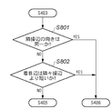
ステップS404において、注目アンカーポイントが、曲率大の点であるか否かが判定される。ここで、図8は、注目アンカーポイントを曲率大の点として判定する方法について説明するフローチャートである。図8に示すように、まず、ステップS801において、隣接辺のベクトルの向きが同一か否かが判定される。ここで、隣接辺のベクトルの向きが同一であると判定された場合には、注目アンカーポイントにおける曲率は小と判断され、注目アンカーポイントは、第2優先データに分類分けされる(ステップS406)。図9は、注目アンカーポイントが、第2優先グループとして分類分けされた一例を示す図である。図9に示すように、隣接辺のベクトルの向きが同一であるので、注目アンカーポイントは、曲率大の点ではなく、変曲点として判断され、第2優先データに分類分けされている。ステップS801において、隣接辺のベクトルの向きが互いに異なると判定された場合には、ステップS802に進む。ステップS802において、着目辺と隣隣接辺(隣々接辺とも表記する)との長さが比較される。図10は、着目辺と隣隣接辺との長さの比較を説明する図である。図10に示すように、隣隣接辺a及びbの長さの合計の1/2が、着目辺の長さxよりも大きい場合に、ステップS802において、着目辺は隣隣接辺より短いと判定される。その場合に、注目アンカーポイントは、第2優先データに分類分けされる(ステップS406)。図11は、着目辺と隣隣接辺との長さの比較を説明する他の図である。図11に示すように、隣隣接辺a及びbの長さの合計の1/2が、着目辺の長さxよりも小さい場合に、ステップS802において、着目辺は隣隣接辺より長いと判定される。その場合に、注目アンカーポイントは、曲率大の点(以下、曲率点ともいう)として判定され、第1優先データに分類分けされる(ステップS405)。上記の隣隣接辺a及びbの長さの合計の1/2の値は、基準の曲率として、予め、画像処理装置におけるメモリ等の記憶領域に格納されていても良い。 In step S404, it is determined whether or not the attention anchor point is a point with a large curvature. Here, FIG. 8 is a flowchart for explaining a method of determining the anchor point of interest as a point having a large curvature. As shown in FIG. 8, first, in step S801, it is determined whether or not the directions of adjacent side vectors are the same. Here, when it is determined that the directions of the adjacent side vectors are the same, the curvature at the target anchor point is determined to be small, and the target anchor point is classified into second priority data (step S406). . FIG. 9 is a diagram illustrating an example in which attention anchor points are classified as a second priority group. As shown in FIG. 9, since the directions of the vectors on the adjacent sides are the same, the anchor point of interest is determined as an inflection point rather than a point with a large curvature, and is classified into second priority data. If it is determined in step S801 that the directions of the adjacent side vectors are different from each other, the process proceeds to step S802. In step S802, the lengths of the side of interest and the adjacent adjacent side (also referred to as the adjacent tangent side) are compared. FIG. 10 is a diagram for explaining a comparison of lengths between the target side and the adjacent adjacent side. As shown in FIG. 10, when the half of the total length of adjacent adjacent sides a and b is larger than the length x of the target side, it is determined in step S802 that the target side is shorter than the adjacent side. Is done. In that case, the anchor point of interest is classified into second priority data (step S406). FIG. 11 is another diagram for explaining the comparison of the length between the target side and the adjacent adjacent side. As shown in FIG. 11, when the half of the total length of adjacent adjacent sides a and b is smaller than the length x of the target side, it is determined in step S802 that the target side is longer than the adjacent adjacent side. Is done. In this case, the attention anchor point is determined as a point having a large curvature (hereinafter also referred to as a curvature point), and is classified into first priority data (step S405). A value that is ½ of the total length of the adjacent adjacent sides a and b may be stored in advance in a storage area such as a memory in the image processing apparatus as a reference curvature.
図4に示すフローチャートに従って、注目アンカーポイント及び付随するコントロールポイントが、第1優先データ又は第2優先データに分類分けされると、画像処理装置は、他のアンカーポイントを注目アンカーポイントとして図4に示す判定を繰り返す。画像処理装置は、図4に示す判定を、ベクトル化されたオブジェクトにおいて抽出されたアンカーポイント全てについて行う。第1優先データ又は第2優先データに分類分けされたアンカーポイントは、図2に示すファイル構成部203に出力される。
When the anchor point of interest and the accompanying control point are classified into the first priority data or the second priority data according to the flowchart shown in FIG. 4, the image processing apparatus sets other anchor points as the attention anchor points in FIG. Repeat the determination shown. The image processing apparatus performs the determination shown in FIG. 4 for all anchor points extracted in the vectorized object. The anchor points classified into the first priority data or the second priority data are output to the
図12は、ファイル構成部203において生成されるファイルのデータ構成を示す図である。図12に示すように、ファイルは、第1優先データ格納領域と、第2優先データ格納領域と、圧縮データ格納領域とを含んでいる。第1優先データ格納領域には、図4において第1優先データとして分類されたアンカーポイント及び付随するコントロールポイントが格納される。また、第2優先データ格納領域には、図4において第2優先データとして分類されたアンカーポイント及び付随するコントロールポイントが格納される。圧縮データ格納領域には、符号化部201によって圧縮された背景領域が格納される。図12においては、第1優先データ格納領域が、ファイルの先頭から格納されているが、第1優先データ格納領域と第2優先データ格納領域とが区別されるのであれば、特に、図12に示すような構成でなくても良い。
FIG. 12 is a diagram illustrating a data configuration of a file generated by the
図12のように構成されたファイルが、ハードディスク103に格納される。既に説明したように、第1優先データ格納領域に格納されているアンカーポイント及び付随するコントロールポイントは、オブジェクトにおいての端点、角点、突起点、曲率大の点のいずれかである。従って、画像処理装置が、出力ファイル生成部104において第1優先データ格納領域に格納されているデータを読み出すことによって、オブジェクトの概略を描画することができる。また、画像処理装置におけるCPU等によって、第1優先データ格納領域に格納されているデータが読み出される際に、その領域の先頭アドレスと終端アドレスが認識されていれば良い。従って、概略描画用のデータの読出し処理を簡易化し、高速化することができる。
A file configured as shown in FIG. 12 is stored in the
例えば、ユーザが、図示されていないインタフェースによって、ハードディスク103に保存された図12に示すファイルの印刷を指示するとする。その場合に、出力ファイル生成部104は、図12に示すファイルに含まれる全てのデータをハードディスク103から読み出し、出力部105に送信する。出力部105は、送信された画像を印字する。
For example, it is assumed that the user instructs printing of the file shown in FIG. 12 stored in the
また、ユーザが、図示されていないインタフェースによって、概略描画用のデータについてセンド機能を指示するとする。その場合に、ハードディスク103に保存された図12に示すファイルが出力ファイル生成部104によって読み出される。その際に、第1優先データ格納領域に格納された第1優先データと圧縮データ格納領域に格納された圧縮データのみが抽出され、出力部105に送信される。出力部105は、PDF等のファイルに変換された第1優先データと、圧縮データとをユーザによって指定された送信先のホストコンピュータに送信する。
Further, it is assumed that the user instructs a send function for data for rough drawing through an interface not shown. In that case, the file shown in FIG. 12 stored in the
以上のように、本実施形態において、ハードディスク103に格納されるファイルにおいて、アンカーポイント及び付随するコントロールポイントが格納される領域が、第1優先データ格納領域と第2優先データ格納領域とに分類分けされ階層構造とされている。また、第1優先データ格納領域と第2優先データ格納領域のような分類毎の領域は、アドレス等によって、識別可能とされている。その結果、出力ファイル生成部104が、ハードディスク103に格納されているファイルの一部を抽出してオブジェクトの概略描画を行う処理を簡易化し、高速化することができる。
As described above, in the present embodiment, in the file stored in the
図13は、分類分けされるアンカーポイント及び付随するコントロールポイントを示す図である。図13の(a)は、従来において、ファイルに格納されるアンカーポイント及び付随するコントロールポイントを示している。従来においては、図13の(a)に示すように、ベジエ曲線lを構成するアンカーポイントA、B、C及びコントロールポイントa’、b’、c1’、c2’が、ファイルに格納される。一般的に、アンカーポイントは、曲線が通るポイントであり、コントロールポイントは、曲線の度合いを決定するポイントとして知られている。 FIG. 13 is a diagram showing anchor points and associated control points to be classified. FIG. 13A shows anchor points and associated control points stored in a file in the prior art. Conventionally, as shown in FIG. 13A, anchor points A, B, and C and control points a ', b', c1 ', and c2' constituting Bezier curve l are stored in a file. In general, an anchor point is a point through which a curve passes, and a control point is known as a point that determines the degree of the curve.
一方、本実施形態においては、図13の(b)に示すように、ベジエ曲線lを構成するアンカーポイント及び付随するコントロールポイントが、第1優先データと第2優先データとに分類分けされる。ここで、図13の(a)及び(b)に示すアンカーポイントA及びBは、オブジェクトの輪郭上における端点に分類されているとする。また、アンカーポイントCは、図4において説明した第2優先データに分類されるアンカーポイントとする。従って、図13の(b)に示すように、アンカーポイントA及びBが、第1優先データに分類分けされ、アンカーポイントCが、第2優先データに分類分けされている。 On the other hand, in the present embodiment, as shown in FIG. 13 (b), the anchor points and the accompanying control points constituting the Bezier curve l are classified into first priority data and second priority data. Here, it is assumed that anchor points A and B shown in FIGS. 13A and 13B are classified as end points on the contour of the object. The anchor point C is an anchor point classified as the second priority data described with reference to FIG. Therefore, as shown in FIG. 13B, the anchor points A and B are classified into the first priority data, and the anchor point C is classified into the second priority data.
ここで、コントロールポイントの分類分けについて説明する。図13の(b)に示すように、コントロールポイントa’及びb’と、アンカーポイントCに付随するコントロールポイントc1’及びc2’が、第2優先データに分類分けされている。ここで、アンカーポイントA及びBと、コントロールポイントa及びbとが第1優先データに分類されているとし、第1優先データのみを用いてオブジェクトの概略を描画すると、元のベジエ曲線lよりも画質が低下してしまう。これは、一般的に、アンカーポイントを結ぶベースラインからコントロールポイントを離す程、曲線の立ち上がりが大きくなり、近づける程、曲線の立ち上がりが小さくなる性質を有していることによる。従って、本実施形態においては、第1優先データに分類されるアンカーポイントA及びBについて、コントロールポイントa及びbを付随させている。その場合に、図13の(b)に示すように、ベースラインから離れる方向に、コントロールポイントa及びbが設置される。その結果、元のベジエ曲線lに近い形状を再現することができ、アンカーポイント及びコントロールポイントを分類分けしオブジェクトの概略を描画する際の画質の低下を防ぐことができる。 Here, the control point classification will be described. As shown in FIG. 13B, the control points a 'and b' and the control points c1 'and c2' associated with the anchor point C are classified into second priority data. Here, it is assumed that the anchor points A and B and the control points a and b are classified as the first priority data, and when the outline of the object is drawn using only the first priority data, the original Bezier curve l is drawn. The image quality will deteriorate. This is because the rising of the curve generally increases as the control point is moved away from the base line connecting the anchor points, and the rising of the curve becomes smaller as the control point is closer. Therefore, in the present embodiment, the control points a and b are attached to the anchor points A and B classified as the first priority data. In this case, as shown in FIG. 13B, control points a and b are installed in a direction away from the baseline. As a result, it is possible to reproduce a shape close to the original Bezier curve l, and to prevent deterioration in image quality when the anchor points and control points are classified and the outline of the object is drawn.
また、更に、第2優先データも用いてオブジェクトの描画を行う場合には、コントロールポイントa及びbを用いず、第1優先データと第2優先データとの階層構造を導入する前のコントロールポイントa’及びb’を用いる。 Furthermore, when the object is drawn using the second priority data, the control point a and b are not used, and the control point a before introducing the hierarchical structure of the first priority data and the second priority data. Use 'and b'.
次に、本実施形態における他の例について説明する。図14は、本実施形態におけるアンカーポイント及びコントロールポイントの分類分けの他の例について説明する図である。図13の(b)に示す例においては、アンカーポイントC及び付随するコントロールポイントc1’、c2’が、ポイント決定部2021から出力され、第2優先データとして、ファイル構成部203に送信され、ファイルに格納されている。しかしながら、本例において、アンカーポイントCは、ファイル構成部203に送信されない。その結果、本例において、ファイルの第1優先データ格納領域には、アンカーポイントA、B及び付随するコントロールポイントa、bが格納され、第2優先データ格納領域には、コントロールポイントa’、b’が格納される。
Next, another example in the present embodiment will be described. FIG. 14 is a diagram illustrating another example of the classification of anchor points and control points in the present embodiment. In the example shown in FIG. 13B, the anchor point C and the accompanying control points c1 ′ and c2 ′ are output from the
本例におけるオブジェクトの概略の描画については、図13の(b)の場合と同様に、第1優先データによって行われる。一方、第1優先データ及び第2優先データを読出しオブジェクトを描画する場合には、第1優先データの描画の際に、アンカーポイントA及びB間の曲線上の凸点の座標をアンカーポイントCとして決定する。更に、第2優先データ領域に格納されているコントロールポイントa’及びb’と、決定されたアンカーポイントC及び付随するコントロールポイントc1’、c2’とによって、オブジェクトが描画される。本例におけるアンカーポイントCは、例えば、ファイル構成部203において決定されるようにしても良い。
Similar to the case of FIG. 13B, the rough drawing of the object in this example is performed by the first priority data. On the other hand, when the first priority data and the second priority data are read and the object is drawn, the coordinates of the convex point on the curve between the anchor points A and B are set as the anchor point C when the first priority data is drawn. decide. Further, the object is drawn by the control points a 'and b' stored in the second priority data area, the determined anchor point C and the accompanying control points c1 'and c2'. The anchor point C in this example may be determined by the
以上のように、本例においては、第1優先データによって描画される際に、第2優先データのアンカーポイントCが自動的に決定されるので、図12に示すファイルの第2優先データ領域にアンカーポイントCを格納しておく必要がない。その結果、図13の(a)に示す7個のポイントを格納していた従来例と比べて、ファイルに格納するデータ量を6個と低減することができ、本実施形態におけるアンカーポイント及びコントロールポイントの分類分けに伴うファイルの増加を防ぐことができる。 As described above, in this example, when rendering is performed with the first priority data, the anchor point C of the second priority data is automatically determined. Therefore, in the second priority data area of the file shown in FIG. There is no need to store the anchor point C. As a result, the amount of data stored in the file can be reduced to 6 as compared with the conventional example in which 7 points shown in FIG. 13A are stored, and the anchor points and controls in this embodiment can be reduced. It is possible to prevent an increase in files due to the point classification.
本例においては、ファイル構成部203において決定される第2優先データのアンカーポイントCは、アンカーポイントA及びB間の曲線上の凸点の座標とされているが、特に凸点とされなくても良い。例えば、曲線上の所定の変曲点の位置、即ち座標をアンカーポイントCと決定するようにしても良い。
In this example, the anchor point C of the second priority data determined by the
本例において、ファイルに格納されるアンカーポイントは、アンカーポイントA及びBのみであるので、ファイル構成部203においてアンカーポイントCを第2優先データとして算出した後、更に新たなアンカーポイントDを算出するようにしても良い。例えば、その場合に、アンカーポイントDは、アンカーポイントAとCの間の凸点とするように決定しても良い。また、その決定されたアンカーポイントDを、第3優先データとして、図12に示すファイルのデータ構成を、更に階層化するようにしても良い。
In this example, the anchor points stored in the file are only the anchor points A and B. Therefore, after the anchor point C is calculated as the second priority data in the
更に、本実施形態における他の例について説明する。本例においては、図13の(b)と同様に、アンカーポイントA及びBと、コントロールポイントa及びbとが第1優先データとしてファイルに格納されている。また、アンカーポイントCと、コントロールポイントa’、b’、c1’、c2’が第2優先データとしてファイルに格納されている。本例においては、第1優先データにおける接線Aaの傾きと、第2優先データにおける接線Aa’の傾きとを一致させるように、コントロールポイントaの座標値を決定する。同様に、第1優先データにおける接線Bbの傾きと、第2優先データにおける接線Bb’の傾きとを一致させるように、コントロールポイントbの座標値を決定する。従って、第2優先データ格納領域に格納されるコントロールポイントa’及びb’の座標値は、x座標値又はy座標値のいずれか1つであれば良い。 Furthermore, another example in the present embodiment will be described. In this example, as in FIG. 13B, anchor points A and B and control points a and b are stored in the file as first priority data. Also, the anchor point C and the control points a ', b', c1 ', c2' are stored in the file as second priority data. In this example, the coordinate value of the control point a is determined so that the slope of the tangent line Aa in the first priority data matches the slope of the tangent line Aa 'in the second priority data. Similarly, the coordinate value of the control point b is determined so that the slope of the tangent line Bb in the first priority data matches the slope of the tangent line Bb ′ in the second priority data. Accordingly, the coordinate values of the control points a ′ and b ′ stored in the second priority data storage area may be any one of the x coordinate value and the y coordinate value.
従って、本例においては、図13の(b)に示す例と比べて、データ量を低減することができ、本実施形態におけるアンカーポイント及びコントロールポイントの分類分けに伴うファイルの増加を抑えることができる。 Therefore, in this example, the amount of data can be reduced as compared with the example shown in FIG. 13B, and the increase in files due to the classification of anchor points and control points in this embodiment can be suppressed. it can.
本実施形態において、ベクトル化手法としてベジエ曲線法が用いられているが、画像中のオブジェクトの輪郭を近似する他の方法が用いられても良い。また、JPEG方式が画像圧縮法として用いられているが、他の画像圧縮法が用いられても良い。更に、文字がベクトル化の対象とされているが、グラフやクリップアート等がベクトル化の対象とされても良い。 In this embodiment, the Bezier curve method is used as the vectorization method, but other methods for approximating the contour of the object in the image may be used. The JPEG method is used as the image compression method, but other image compression methods may be used. Furthermore, although characters are targeted for vectorization, graphs, clip art, and the like may be targeted for vectorization.
本発明には、プログラムコード(画像処理プログラム)の指示に基づき、コンピュータ上で稼働しているオペレーティングシステム(OS)などが実際の処理の一部または全部を行い、その処理によって前述した実施形態の機能が実現される場合も含まれる。更に、記憶媒体から読み出されたプログラムコードが、コンピュータに挿入された機能拡張カードやコンピュータに接続された機能拡張ユニットに備わるメモリに書込まれた場合についても、本発明は適用される。その場合、書き込まれたプログラムコードの指示に基づき、その機能拡張カードや機能拡張ユニットに備わるCPUなどが実際の処理の一部または全部を行い、その処理によって前述した実施形態の機能が実現される。 In the present invention, an operating system (OS) operating on a computer performs part or all of actual processing based on an instruction of a program code (image processing program), and the processing of the above-described embodiment is performed by the processing. This includes cases where functions are realized. Furthermore, the present invention is also applied to the case where the program code read from the storage medium is written in a memory provided in a function expansion card inserted into the computer or a function expansion unit connected to the computer. In that case, the CPU of the function expansion card or function expansion unit performs part or all of the actual processing based on the instruction of the written program code, and the functions of the above-described embodiments are realized by the processing. .
例えば、システム又は装置のコンピュータ(CPUやMPU)が、メモリ等のコンピュータ読み取り可能なプログラム記録媒体に格納されたプログラムコードを読出し実行しても良い。その場合、プログラム記録媒体から読み出されたプログラムコード自体が上記実施形態の機能を実現することとなり、そのプログラムコードを記録した記録媒体により本発明が構成される。 For example, a computer (CPU or MPU) of the system or apparatus may read and execute a program code stored in a computer-readable program recording medium such as a memory. In that case, the program code itself read from the program recording medium realizes the functions of the above-described embodiment, and the present invention is configured by the recording medium recording the program code.
101 スキャン部
102 スキャンデータファイル化部
103 ハードディスク
104 出力ファイル生成部
105 出力部
201 符号化部
202 ベクトル化部
203 ファイル構成部
204 ブロックセレクション部
2021 ポイント決定部
2022 分類部
DESCRIPTION OF
Claims (13)
前記抽出された複数のアンカーポイントのうち、前記オブジェクトの輪郭の所定の特徴を有する部分に該当するアンカーポイントを第1のグループに分類し、前記所定の特徴を有する部分に該当しないアンカーポイントを第2のグループに分類する分類手段と、
前記分類手段によって分類された前記第1のグループと前記第2のグループとを識別可能な状態で、前記複数のアンカーポイントを保存する保存手段と、
を備えることを特徴とする画像処理装置。 A point determination means for extracting a plurality of anchor points and control points by approximating the contour of an object as a function;
Among the plurality of extracted anchor points, the anchor points corresponding to a part having a predetermined characteristic of the contour of the object are classified into a first group, and anchor points not corresponding to the part having the predetermined characteristic are classified into a first group. Classification means for classifying into two groups ;
Storage means for storing the plurality of anchor points in a state where the first group and the second group classified by the classification means can be identified ;
An image processing apparatus comprising:
前記第1のグループに分類された前記アンカーポイントと、前記第1のグループに分類された前記アンカーポイントにより決定される曲線上に位置し前記第2のグループとして分類されるべきアンカーポイントとを用いて描画を行い、当該描画された結果を前記オブジェクトとして出力する出力手段、を更に備えることを特徴とする請求項1記載の画像処理装置。 When the storage means does not store the anchor points classified into the second group among the plurality of anchor points ,
Using the anchor points classified into the first group and the anchor points to be classified as the second group located on a curve determined by the anchor points classified into the first group performs drawing Te, the image processing apparatus of the output means of the rendered result is output as the object, and further comprising a claim 1.
前記画像処理装置の決定手段が、オブジェクトの輪郭を関数近似して複数のアンカーポイントとコントロールポイントとを抽出するポイント決定工程と、
前記画像処理装置の分類手段が、前記抽出された複数のアンカーポイントのうち、前記オブジェクトの輪郭の所定の特徴を有する部分に該当するアンカーポイントを第1のグループに分類し、前記所定の特徴を有する部分に該当しないアンカーポイントを第2のグループに分類する分類工程と、
前記画像処理装置の保存手段が、前記分類工程によって分類された前記第1のグループと前記第2のグループとを識別可能な状態で、前記複数のアンカーポイントを保存する保存工程と、
を有することを特徴とする画像処理方法。 An image processing method executed in an image processing apparatus,
A point determining step in which the determining means of the image processing apparatus extracts a plurality of anchor points and control points by approximating the contour of the object as a function;
The classifying means of the image processing apparatus classifies the anchor points corresponding to a portion having a predetermined characteristic of the contour of the object among the plurality of extracted anchor points into a first group, and the predetermined characteristic is A classification step of classifying the anchor points that do not correspond to the portion having the second group ;
A storage step of storing the plurality of anchor points in a state in which the storage unit of the image processing apparatus can identify the first group and the second group classified by the classification step;
An image processing method comprising:
Priority Applications (3)
| Application Number | Priority Date | Filing Date | Title |
|---|---|---|---|
| JP2007238386A JP5017031B2 (en) | 2007-09-13 | 2007-09-13 | Image processing apparatus, image processing method, image processing program, and storage medium |
| US12/197,676 US8326039B2 (en) | 2007-09-13 | 2008-08-25 | Image processing apparatus, image processing method, and recording medium |
| CN2008101495754A CN101388111B (en) | 2007-09-13 | 2008-09-12 | Image processing device and method |
Applications Claiming Priority (1)
| Application Number | Priority Date | Filing Date | Title |
|---|---|---|---|
| JP2007238386A JP5017031B2 (en) | 2007-09-13 | 2007-09-13 | Image processing apparatus, image processing method, image processing program, and storage medium |
Publications (3)
| Publication Number | Publication Date |
|---|---|
| JP2009071626A JP2009071626A (en) | 2009-04-02 |
| JP2009071626A5 JP2009071626A5 (en) | 2010-10-28 |
| JP5017031B2 true JP5017031B2 (en) | 2012-09-05 |
Family
ID=40454516
Family Applications (1)
| Application Number | Title | Priority Date | Filing Date |
|---|---|---|---|
| JP2007238386A Expired - Fee Related JP5017031B2 (en) | 2007-09-13 | 2007-09-13 | Image processing apparatus, image processing method, image processing program, and storage medium |
Country Status (3)
| Country | Link |
|---|---|
| US (1) | US8326039B2 (en) |
| JP (1) | JP5017031B2 (en) |
| CN (1) | CN101388111B (en) |
Families Citing this family (12)
| Publication number | Priority date | Publication date | Assignee | Title |
|---|---|---|---|---|
| US9153064B2 (en) * | 2009-12-23 | 2015-10-06 | Intel Corporation | Grouping pixels to be textured |
| JP5566158B2 (en) * | 2010-03-30 | 2014-08-06 | キヤノン株式会社 | Image processing method, image processing apparatus, and program |
| JP5629483B2 (en) | 2010-03-30 | 2014-11-19 | キヤノン株式会社 | Image processing method, image processing apparatus, and program |
| CN102947841A (en) | 2010-04-30 | 2013-02-27 | 沃康普公司 | Spiculated malignant mass detection and classification in radiographic image |
| US9256799B2 (en) * | 2010-07-07 | 2016-02-09 | Vucomp, Inc. | Marking system for computer-aided detection of breast abnormalities |
| CN102881033B (en) * | 2012-08-06 | 2018-06-19 | 西安科技大学 | The generation method and device of adaptive curve |
| US9183467B2 (en) * | 2013-05-03 | 2015-11-10 | Microsoft Technology Licensing, Llc | Sketch segmentation |
| US9147125B2 (en) | 2013-05-03 | 2015-09-29 | Microsoft Technology Licensing, Llc | Hand-drawn sketch recognition |
| CN104778653A (en) * | 2014-11-28 | 2015-07-15 | 浙江工商大学 | Image registration method |
| US10212457B1 (en) * | 2015-11-17 | 2019-02-19 | Evernote Corporation | Coordinated piecewise bezier vectorization |
| US11372529B1 (en) | 2021-08-03 | 2022-06-28 | Adobe Inc. | Digital image object anchor points |
| US20230351650A1 (en) * | 2022-04-28 | 2023-11-02 | Dassault Systemes Solidworks Corporation | Converting images to sketches that are modifiable using computer-aided design (cad) software |
Family Cites Families (15)
| Publication number | Priority date | Publication date | Assignee | Title |
|---|---|---|---|---|
| JPH0326592A (en) | 1989-06-23 | 1991-02-05 | Nippon Zeon Co Ltd | Development sheet and coating composition therefor |
| IT1231642B (en) | 1989-07-13 | 1991-12-18 | Polese Pasquale | MOUTHPIECE WITH CIGARETTE FILTER TO ELIMINATE THE VICE OF SMOKING |
| JP3026592B2 (en) | 1990-10-22 | 2000-03-27 | キヤノン株式会社 | Outline extraction method and apparatus |
| JPH05114002A (en) * | 1991-10-23 | 1993-05-07 | Mitsubishi Heavy Ind Ltd | Device for designing free curve |
| JP3049672B2 (en) | 1991-12-26 | 2000-06-05 | キヤノン株式会社 | Image processing method and apparatus |
| JP3194779B2 (en) * | 1992-05-11 | 2001-08-06 | 株式会社リコー | Filling device |
| JPH05328144A (en) * | 1992-05-15 | 1993-12-10 | Canon Inc | Picture communication equipment |
| JPH06282658A (en) * | 1993-03-24 | 1994-10-07 | Mutoh Ind Ltd | Method and device for generating curved line data |
| JP3474037B2 (en) * | 1995-10-12 | 2003-12-08 | シャープ株式会社 | Character pattern generator |
| JPH09185722A (en) * | 1995-12-27 | 1997-07-15 | Brother Ind Ltd | Method and device for setting curve approximation dividing point |
| KR0172581B1 (en) | 1996-04-02 | 1999-03-30 | 이진기 | Transformation and rendering method for progressively renderable font |
| US7251365B2 (en) * | 2002-07-03 | 2007-07-31 | Vadim Fux | Scalable stroke font system and method |
| JP4371911B2 (en) * | 2004-05-31 | 2009-11-25 | キヤノン株式会社 | Functionalization processing method and functionalization processing apparatus |
| US7873218B2 (en) | 2004-04-26 | 2011-01-18 | Canon Kabushiki Kaisha | Function approximation processing method and image processing method |
| JP5106768B2 (en) * | 2005-09-29 | 2012-12-26 | 富士通株式会社 | Outline font compression method |
-
2007
- 2007-09-13 JP JP2007238386A patent/JP5017031B2/en not_active Expired - Fee Related
-
2008
- 2008-08-25 US US12/197,676 patent/US8326039B2/en not_active Expired - Fee Related
- 2008-09-12 CN CN2008101495754A patent/CN101388111B/en active Active
Also Published As
| Publication number | Publication date |
|---|---|
| CN101388111A (en) | 2009-03-18 |
| CN101388111B (en) | 2013-06-05 |
| US20090074302A1 (en) | 2009-03-19 |
| US8326039B2 (en) | 2012-12-04 |
| JP2009071626A (en) | 2009-04-02 |
Similar Documents
| Publication | Publication Date | Title |
|---|---|---|
| JP5017031B2 (en) | Image processing apparatus, image processing method, image processing program, and storage medium | |
| US8274667B2 (en) | Image processing apparatus, control method thereof, and storage medium storing a program for converting raster image data into block vector image format | |
| US7680358B2 (en) | Image processing apparatus and control method thereof, and program | |
| JP4766657B2 (en) | Image processing apparatus, control method therefor, and program | |
| JP5209953B2 (en) | Image data supply apparatus and image data supply method | |
| US8855438B2 (en) | Image processing apparatus, image processing method of image processing apparatus, and program | |
| JP5049920B2 (en) | Image processing apparatus and image processing method | |
| JP4424845B2 (en) | Image data compression method and decompression method | |
| JP2010074540A (en) | Image processing apparatus | |
| JP5049921B2 (en) | Image processing apparatus and image processing method | |
| JP4582204B2 (en) | Image processing apparatus, image conversion method, and computer program | |
| JP4991590B2 (en) | Image processing apparatus, image processing method, image processing program, and storage medium | |
| JP5049922B2 (en) | Image processing apparatus and image processing method | |
| JP5335581B2 (en) | Image processing apparatus, image processing method, and program | |
| JP4605260B2 (en) | Vector image generation method, image processing apparatus, and computer program | |
| JPH09261457A (en) | Print controller, data processing method for it and storage medium storing program readable by computer | |
| JP2008042345A (en) | Image processing method and image processor | |
| JP7301529B2 (en) | Image processing device, image processing method, and program | |
| JP4324058B2 (en) | Image processing apparatus and method | |
| JP5517028B2 (en) | Image processing device | |
| JPH08237404A (en) | Selection of optical character recognition mode | |
| JP7185451B2 (en) | Image processing device, image processing method, and program | |
| JP3814547B2 (en) | Image processing apparatus and method | |
| JP4390723B2 (en) | Information embedding device, information extracting device, information embedding method, information extracting method, information embedding program, information extracting program, and recording medium | |
| JP2018180872A (en) | Document processing device and program |
Legal Events
| Date | Code | Title | Description |
|---|---|---|---|
| A521 | Request for written amendment filed |
Free format text: JAPANESE INTERMEDIATE CODE: A523 Effective date: 20100910 |
|
| A621 | Written request for application examination |
Free format text: JAPANESE INTERMEDIATE CODE: A621 Effective date: 20100910 |
|
| A977 | Report on retrieval |
Free format text: JAPANESE INTERMEDIATE CODE: A971007 Effective date: 20120118 |
|
| A131 | Notification of reasons for refusal |
Free format text: JAPANESE INTERMEDIATE CODE: A131 Effective date: 20120127 |
|
| A521 | Request for written amendment filed |
Free format text: JAPANESE INTERMEDIATE CODE: A523 Effective date: 20120327 |
|
| TRDD | Decision of grant or rejection written | ||
| A01 | Written decision to grant a patent or to grant a registration (utility model) |
Free format text: JAPANESE INTERMEDIATE CODE: A01 Effective date: 20120514 |
|
| A01 | Written decision to grant a patent or to grant a registration (utility model) |
Free format text: JAPANESE INTERMEDIATE CODE: A01 |
|
| A61 | First payment of annual fees (during grant procedure) |
Free format text: JAPANESE INTERMEDIATE CODE: A61 Effective date: 20120611 |
|
| FPAY | Renewal fee payment (event date is renewal date of database) |
Free format text: PAYMENT UNTIL: 20150615 Year of fee payment: 3 |
|
| R151 | Written notification of patent or utility model registration |
Ref document number: 5017031 Country of ref document: JP Free format text: JAPANESE INTERMEDIATE CODE: R151 |
|
| FPAY | Renewal fee payment (event date is renewal date of database) |
Free format text: PAYMENT UNTIL: 20150615 Year of fee payment: 3 |
|
| LAPS | Cancellation because of no payment of annual fees |