JP5014872B2 - Liquid discharge device cartridge and liquid discharge device including the same - Google Patents
Liquid discharge device cartridge and liquid discharge device including the same Download PDFInfo
- Publication number
- JP5014872B2 JP5014872B2 JP2007125846A JP2007125846A JP5014872B2 JP 5014872 B2 JP5014872 B2 JP 5014872B2 JP 2007125846 A JP2007125846 A JP 2007125846A JP 2007125846 A JP2007125846 A JP 2007125846A JP 5014872 B2 JP5014872 B2 JP 5014872B2
- Authority
- JP
- Japan
- Prior art keywords
- liquid
- discharge
- cartridge
- check valve
- pump
- Prior art date
- Legal status (The legal status is an assumption and is not a legal conclusion. Google has not performed a legal analysis and makes no representation as to the accuracy of the status listed.)
- Expired - Fee Related
Links
Images


Abstract
Description
この発明は、一般的には液体吐出装置用のカートリッジおよびそれを備えた液体吐出装置に関し、特定的には、複数の種類の液体について、それぞれ所定量の液体を吐出するための液体吐出装置に用いられるカートリッジおよびそれを備えた液体吐出装置に関する。 The present invention generally relates to a cartridge for a liquid ejecting apparatus and a liquid ejecting apparatus including the same, and more specifically, to a liquid ejecting apparatus for ejecting a predetermined amount of liquid for each of a plurality of types of liquid. The present invention relates to a cartridge to be used and a liquid discharge apparatus including the cartridge .
従来、液体を吐出する装置においては、液体を収容する容器内の液体を替えることによって、吐出される液体を変更することができる。液体の種類の変更は、本体に接続されている、液体を収容する容器ごと変更することによって行なわれる。一回当たりの吐出量や、一定時間当たりに必要とされる吐出量は、液体の種類によって異なるため、容器の内部に収容されている液体の種類を判別して、液体吐出用装置の本体が吐出量を調整する。 2. Description of the Related Art Conventionally, in a device for discharging a liquid, the liquid to be discharged can be changed by changing the liquid in a container that stores the liquid. The type of the liquid is changed by changing the container that stores the liquid connected to the main body. Since the discharge amount per time and the discharge amount required per fixed time differ depending on the type of liquid, the type of liquid contained in the container is determined, and the main body of the liquid discharge device is Adjust the discharge rate.
例えば、特開2005−224503号公報(特許文献1)に記載されている香料等噴射装置は、カートリッジの内部に充填されている香料または有効成分の種別を香料等噴射装置が検知するための被検知部をカートリッジに設けている。香料等噴射装置の検知部が被検知部を読み取ってカートリッジに格納されている香料または有効成分を識別し、所定量の香料または有効成分を噴射するために駆動信号を制御する。
しかしながら、特開2005−224503号公報(特許文献1)に記載されている香料等噴射装置のように、香料等噴射装置の本体が、カートリッジから、カートリッジに充填されている香料または有効成分の情報を読み取るためには、カートリッジにIDタグなどを備える必要があり、製作費用が高くなる。また、本体の出荷時に想定された吐出量の管理しかできないので、新たな香料等に対応することができない。使用者がカートリッジの表示を読み取って本体に内容液の情報を入力する方法は、煩雑であるし、誤入力のおそれがある。 However, as in the fragrance injection device described in Japanese Patent Application Laid-Open No. 2005-224503 (Patent Document 1), the main body of the fragrance injection device is information on the fragrance or active ingredient filled in the cartridge from the cartridge. In order to read the data, it is necessary to provide the cartridge with an ID tag or the like, which increases the manufacturing cost. Moreover, since only the discharge amount assumed at the time of shipment of the main body can be managed, it is not possible to deal with new fragrances. The method in which the user reads the display on the cartridge and inputs the information on the content liquid into the main body is complicated and may cause erroneous input.
新しいカートリッジを装着するときには、ポンプの内部は空であるため液体の頭出しが必要になるが、頭出しのために捨て吐出するまで液体の吐出を行なうと、吐出する液体が香料の場合は余計なにおいや不必要に強いにおいが発生してしまう。また、液体が無駄に消費され、高価な香料や薬品の場合は、無駄な費用が発生する。 When installing a new cartridge, it is necessary to cue the liquid because the inside of the pump is empty. However, if the liquid is discharged until it is discarded for cueing, if the discharged liquid is a fragrance, it will be extra. Odor and unnecessarily strong odor will be generated. In addition, the liquid is wasted, and in the case of expensive fragrances and chemicals, wasteful costs are generated.
カートリッジを交換して新しいカートリッジを装着する場合、新しいカートリッジの内部に収容されている香料が、カートリッジの交換前に収容されていた香料と別の種類の香料であると、ポンプの内部にカートリッジ交換前の香料が少しでも残っていると香料のにおいが混ざって、カートリッジ交換後の香料の本来の香りを発生させることができない。カートリッジに収容されている液体が薬品の場合は、新しいカートリッジに収容されている薬品と、ポンプ内に残っている薬品とが化学反応を起こす可能性がある。そのため、カートリッジの交換時にポンプや配管の洗浄が必要である。 When replacing the cartridge and installing a new cartridge, if the fragrance contained in the new cartridge is a different fragrance from the fragrance contained before the cartridge replacement, the cartridge is replaced inside the pump. If any previous fragrance remains, the odor of the fragrance is mixed, and the original fragrance of the fragrance after the cartridge replacement cannot be generated. When the liquid stored in the cartridge is a chemical, the chemical stored in the new cartridge and the chemical remaining in the pump may cause a chemical reaction. Therefore, it is necessary to clean the pump and piping when replacing the cartridge.
また、現在装着されているカートリッジを収容されている液体が異なるカートリッジと交換することによって、異なる液体をポンプから吐出することができるが、ポンプの材料をカートリッジに収容される全ての液体に耐える材料で構成する必要がある。 Also, by replacing the currently installed cartridge with a cartridge that contains different liquids, different liquids can be discharged from the pump, but the material of the pump can withstand all liquids contained in the cartridge. It is necessary to consist of.
カートリッジの内部に残っている液体が古くなるなどしてそのカートリッジを続けて使用することができなくなった場合は、ポンプや配管内に残っている液体を排出して、配管やポンプの内部を洗浄してから新たなカートリッジを装着しなければならない。このとき、ポンプや配管内から排出する香料等の液体をそのまま放置することはできないので、排出された液体を回収する必要がある。 If the liquid remaining in the cartridge becomes old and cannot be used continuously, drain the liquid remaining in the pump and piping to clean the piping and pump. A new cartridge must then be installed. At this time, since the liquid such as the fragrance discharged from the pump or the pipe cannot be left as it is, it is necessary to collect the discharged liquid.
また、ポンプや配管内で、液体の変質による詰まりなどが発生した場合には、洗浄用の液等で洗う必要がある。このように、作業が繁雑である。 Further, when clogging or the like occurs due to deterioration of the liquid in the pump or piping, it is necessary to wash with a cleaning liquid or the like. Thus, the work is complicated.
カートリッジの装着時には、カートリッジから配管、ポンプまでの経路に空気が混入する場合があるが、ポンプ内に空気が混入していると、所定量の液体が吐出されないことがある。 When the cartridge is mounted, air may be mixed in the path from the cartridge to the pipe and the pump. However, if air is mixed in the pump, a predetermined amount of liquid may not be discharged.
そこで、この発明の目的は、液体吐出装置が液体の種類を判別する必要なく所定量の液体を吐出することが可能であり、吐出させる液体を簡単に交換することができる液体吐出装置用カートリッジおよびそれを備えた液体吐出装置を提供することである。 SUMMARY OF THE INVENTION An object of the present invention is to provide a cartridge for a liquid ejecting apparatus that can eject a predetermined amount of liquid without the need for the liquid ejecting apparatus to determine the type of the liquid, and to easily replace the liquid to be ejected. It is an object of the present invention to provide a liquid ejection apparatus including the same.
この発明に従った液体吐出装置用カートリッジは、液体を収容するための容器と、外部から与えられる駆動信号によって駆動されて、容器内の液体を外部に吐出するためのポンプとを備えている。ポンプは、ポンプ室と、外部から与えられる一定の駆動信号に応じて外部に吐出する液体の量を決定する吐出量決定要素とを有する。外部から与えられる一定の駆動信号は、ポンプを駆動するための一定の交流駆動電圧を有する駆動信号である。吐出量決定要素は、外部から与えられた一定の駆動信号の交流駆動電圧をポンプに供給するための電圧に変更する電圧決定要素と、ポンプ室の容積を変化させるための振動板と、振動板を振動させるための圧電素子とを含む。さらに、この発明に従った液体吐出装置用カートリッジは、駆動信号において所要のサイクル数を選択することによって、圧電素子に供給される電力を調整する選択手段をさらに備えている。 The cartridge for a liquid ejection device according to the present invention includes a container for storing a liquid and a pump that is driven by a drive signal given from the outside and discharges the liquid in the container to the outside . Pump has a pump chamber, a discharge amount determination factor in determining the amount of liquid to be discharged to the outside in accordance with a constant drive signal given from the outside. The constant drive signal given from the outside is a drive signal having a constant AC drive voltage for driving the pump. The discharge amount determining element includes a voltage determining element that changes an AC driving voltage of a constant driving signal given from the outside to a voltage for supplying to the pump, a diaphragm for changing the volume of the pump chamber, and a diaphragm And a piezoelectric element for causing vibration. Furthermore, the cartridge for the liquid ejection device according to the present invention further includes selection means for adjusting the power supplied to the piezoelectric element by selecting the required number of cycles in the drive signal.
このように、液体吐出装置用カートリッジがポンプを備え、そのポンプが吐出量決定要素を有するので、液体の種類に応じて吐出量を決定するために、液体吐出装置は容器内部に収容されている液体の種類を読み取る手段を備える必要がない。容器の内部に収容される液体が新しい液体であっても、液体吐出装置を、新しい液体に対応することができるように変更する必要がない。また、液体吐出装置は、容器の内部に収容されている液体の種類によって個別に吐出量の制御をする必要がないので、制御が簡単になる。 Thus, since the liquid ejection device cartridge includes the pump and the pump has the ejection amount determining element, the liquid ejection device is accommodated inside the container in order to determine the ejection amount according to the type of the liquid. There is no need to provide means for reading the type of liquid. Even if the liquid contained in the container is a new liquid, it is not necessary to change the liquid ejection device so that the liquid can be accommodated. In addition, since the liquid ejection apparatus does not need to individually control the ejection amount depending on the type of liquid contained in the container, the control becomes simple.
さらに、液体を収容するための容器とポンプとが液体吐出装置用カートリッジとして一体であるので、従来のように、ポンプから吐出する液体の種類を変更する場合や、古くなって使用を続けることができなくなった液体吐出装置用カートリッジを別のカートリッジに交換する場合に、ポンプの内部を洗浄する必要がない。また、従来のように、液体が収容される容器を交換した場合に、容器とポンプとの間に空気が残り、ポンプ内に空気が入った状態からポンプ内に液体を吸い込む自給をする必要がない。ポンプ内に空気等が混入することがないので、ポンプの内部を清潔に保つことができ、吐出量が不安定になることがない。容器とポンプの内部の液体が変質して、液体吐出装置用カートリッジの内部において詰まりが発生した場合にも、容器とポンプとが一体に構成されているので、ポンプの内部を洗浄する必要がない。 Furthermore, since the container for storing the liquid and the pump are integrated as a cartridge for the liquid discharge device, the type of liquid discharged from the pump may be changed as in the past, or it may continue to be used as it becomes old. when replacing a liquid ejector cartridge that is no longer in a separate cartridge, there is no need to clean the interior of the pump. In addition, when the container that stores the liquid is replaced as in the past, air remains between the container and the pump, and it is necessary to perform self-supply by sucking the liquid into the pump from the state in which the air has entered the pump. Absent. Since air or the like does not enter the pump, the inside of the pump can be kept clean, and the discharge amount does not become unstable. Even if the liquid inside the container and the pump changes and clogging occurs inside the cartridge for the liquid ejection device, the container and the pump are integrally configured, so there is no need to clean the inside of the pump. .
また、容器の内部に収容する液体に最適な材料で、それぞれの液体吐出装置用カートリッジのポンプを構成することができる。 Moreover, the pump of each cartridge for liquid discharge apparatuses can be comprised with the material optimal for the liquid accommodated in the inside of a container.
また、液体吐出装置用カートリッジを液体吐出装置に接続して直ちに液体を吐出することができる状態や、一定の駆動信号によって液体の頭出しができるようにした状態で出荷することができるので、液体を無駄にする必要がなく、不必要なにおいが発生することもない。 In addition, the liquid ejection device cartridge can be shipped in a state where the liquid ejection device can be connected to the liquid ejection device and the liquid can be ejected immediately, or in a state where the liquid can be cued by a constant drive signal. There is no need to waste any unnecessary odors.
このようにすることにより、液体吐出装置が液体の種類を判別する必要なく所定量の液体を吐出することが可能であり、吐出させる液体を簡単に交換することができる液体吐出装置用カートリッジを提供することができる。 By doing so, a cartridge for a liquid ejection device is provided in which the liquid ejection device can eject a predetermined amount of liquid without having to determine the type of liquid, and the liquid to be ejected can be easily replaced. can do.
この発明に従った液体吐出装置用カートリッジにおいては、ポンプは、ポンプ室と、外部から与えられる一定の駆動信号に応じて外部に吐出する液体の量を決定する吐出量決定要素とを有する。また、ポンプに含まれる吐出量決定要素は、ポンプ室の容積を変化させるための振動板と、振動板を振動させるための圧電素子とを含む。 In the cartridge for the liquid ejection device according to the present invention, the pump includes a pump chamber and a discharge amount determining element that determines the amount of liquid to be discharged to the outside in accordance with a constant drive signal given from the outside. The discharge amount determining element included in the pump includes a diaphragm for changing the volume of the pump chamber and a piezoelectric element for vibrating the diaphragm.
このようにすることにより、ポンプを簡単に駆動することができる。また、ポンプ製作の費用を抑えることができる。 In this way, the pump can be easily driven. Moreover, the cost of manufacturing the pump can be reduced.
この発明に従った液体吐出装置用カートリッジにおいては、外部から与えられる一定の駆動信号は、ポンプを駆動するための一定の交流駆動電圧を有する駆動信号であり、吐出量決定要素は、外部から与えられた一定の駆動信号の交流駆動電圧をポンプに供給するための電圧に変更する電圧決定要素と、振動板と、圧電素子とを含む。 In the cartridge for the liquid ejection device according to the present invention, the constant drive signal given from the outside is a drive signal having a constant AC drive voltage for driving the pump, and the ejection amount determining element is given from the outside. A voltage determining element that changes an AC driving voltage of the constant driving signal to a voltage to be supplied to the pump , a diaphragm, and a piezoelectric element.
このようにすることにより、吐出量を容易に決定することができる。 In this way, the discharge amount can be easily determined.
さらに、この発明に従った液体吐出装置用カートリッジは、選択手段をさらに備えている。選択手段は、駆動信号において所要のサイクル数を選択することによって、圧電素子に供給される電力を調整する。Furthermore, the cartridge for the liquid ejection device according to the present invention further includes a selection unit. The selection means adjusts the electric power supplied to the piezoelectric element by selecting a required number of cycles in the drive signal.
この発明に従った液体吐出装置用カートリッジにおいては、吐出量決定要素は、振動板の材料または形状を含むことが好ましい。 In the liquid ejection device cartridge according to the present invention, the ejection amount determining element preferably includes the material or shape of the diaphragm.
この発明に従った液体吐出装置用カートリッジにおいては、吐出量決定要素は、ポンプ室の容積を変更するための容積変更部材を含むことが好ましい。 In the cartridge for a liquid ejection device according to the present invention, the ejection amount determining element preferably includes a volume changing member for changing the volume of the pump chamber.
この発明に従った液体吐出装置用カートリッジは、容器からポンプ室に液体を吸入するための吸入口と、吸入口において液体の流れを調節するための吸入側逆止弁と、ポンプ室の内部からポンプ室の外部に液体を吐出する吐出口と、吐出口において液体の流れを調節するための吐出側逆止弁と備え、吐出量決定要素は、吸入側逆止弁および/または吐出側逆止弁の硬さを含むことが好ましい。吸入側逆止弁および/または吐出側逆止弁の硬さは、好ましくは、ジュロメータ硬さで表した硬度である。 A cartridge for a liquid discharge device according to the present invention includes a suction port for sucking liquid from a container into a pump chamber, a suction-side check valve for adjusting the flow of liquid at the suction port, and an inside of the pump chamber. A discharge port for discharging liquid to the outside of the pump chamber, and a discharge-side check valve for adjusting the flow of the liquid at the discharge port, the discharge amount determining element being a suction-side check valve and / or a discharge-side check valve It is preferable to include the hardness of the valve. The hardness of the suction side check valve and / or the discharge side check valve is preferably a hardness expressed in durometer hardness.
この発明に従った液体吐出装置用カートリッジは、容器からポンプ室に液体を吸入するための吸入口と、吸入口において液体の流れを調節するための吸入側逆止弁と、ポンプ室の内部からポンプ室の外部に液体を吐出する吐出口と、吐出口において液体の流れを調節するための吐出側逆止弁と、吸入口および/または吐出口が形成される壁部とを備え、吸入側逆止弁および/または吐出側逆止弁は、壁部に押圧されて、それぞれ、吸入口および/または吐出口を閉塞することが可能であるように構成され、吐出量決定要素は、吸入側逆止弁および/または吐出側逆止弁が壁部に押圧されるときの押圧の大きさを含むことが好ましい。 A cartridge for a liquid discharge device according to the present invention includes a suction port for sucking liquid from a container into a pump chamber, a suction-side check valve for adjusting the flow of liquid at the suction port, and an inside of the pump chamber. A suction port for discharging liquid to the outside of the pump chamber, a discharge-side check valve for adjusting the flow of liquid at the discharge port, and a wall portion on which the suction port and / or the discharge port are formed; The check valve and / or the discharge-side check valve are configured to be pressed against the wall portion so as to close the suction port and / or the discharge port, respectively. It is preferable that the amount of pressing when the check valve and / or the discharge-side check valve is pressed against the wall portion is included.
このようにすることにより、簡単に吐出量を決定することができる。 In this way, the discharge amount can be easily determined.
この発明に従った液体吐出装置は、本体と、本体に接続される、上記のいずれかの液体吐出装置用カートリッジを備えることが好ましい。 The liquid ejection device according to the present invention preferably includes a main body and any one of the liquid ejection device cartridges connected to the main body.
このようにすることにより、本体側では液体吐出装置用カートリッジ内に収容されている液体の種類について判断する必要なく、簡単に、その液体に応じた量を吐出することができる。 By doing so, it is possible to easily discharge an amount corresponding to the liquid on the main body side without having to determine the type of liquid contained in the liquid discharge device cartridge .
以上のように、この発明によれば、液体吐出装置が液体の種類を判別する必要なく所定量の液体を吐出することが可能であり、吐出させる液体を簡単に交換することができる液体吐出装置用カートリッジおよびそれを備えた液体吐出装置を提供することができる。 As described above, according to the present invention, it is possible for the liquid ejecting apparatus to eject a predetermined amount of liquid without having to determine the type of the liquid, and the liquid ejecting apparatus that can easily replace the liquid to be ejected. Cartridge and a liquid ejection apparatus including the cartridge can be provided.
以下、この発明の実施の形態を図面に基づいて説明する。 Hereinafter, embodiments of the present invention will be described with reference to the drawings.
(第1実施形態)
図1は、この発明の第1実施形態として、カートリッジの全体を示す断面図である。
(First embodiment)
FIG. 1 is a cross-sectional view showing the entire cartridge as a first embodiment of the present invention.
図1に示すように、液体吐出装置用詰替容器としてカートリッジ100は、タンク部100aとポンプ部100bとを備える。ポンプ部100bは、流路としてのポンプ室110と、外部からポンプ室110に液体を吸入するための吸入口310と、吸入口310において液体の流れを調節するための吸入側逆止弁500と、ポンプ室110の内部からポンプ室110の外部の流路としての吐出管202に液体を吐出する吐出口320と、吐出口320において液体の流れを調節するための吐出側逆止弁600と、壁部として、ポンプ室110の容積を変化させるための振動板210と、吐出量決定要素として、振動板210と、振動板210を振動させるための圧電素子211と、電圧決定要素として電気抵抗710と電気抵抗720を備え、吸入側逆止弁500は、頭部501に形成された突起として頂部503が振動板210に接触するようにポンプ室110に組み込まれている。
As shown in FIG. 1, a
吸入側逆止弁500を介して液体が吸入され、吐出側逆止弁600を介して液体が吐出されるまでの空間がポンプ室110であり、吸入側逆止弁500と吐出側逆止弁600は、それぞれ、壁部としてのハウジング300に形成された吸入側弁座330と吐出側弁座400に取り付けられている。ポンプ室110の底面は振動板210によって形成されている。振動板210の端部は、ハウジング300と振動板側ケース212との間に挿入されて固定されている。振動板210の下面には、圧電素子211が接着されている。圧電素子211の下部には、空間が設けられ、圧電素子211は上下に振動することができる。ハウジング300の上部には、吸入吐出側ケース200が取り付けられており、吸入吐出側ケース200の内部に吐出管202が形成されている。ハウジング300と吸入吐出側ケース200との間には8の字Oリング103が配置されて密閉され、ハウジング300と振動板側ケース212との間にはOリング104が配置されて密閉されている。
A space until the liquid is sucked through the suction-
吸入側逆止弁500と吐出側逆止弁600は、弁の軸を含む縦断面が、相対的に断面積が大きい頭部と相対的に断面積が小さい脚部を有し、開いた傘のような形状をしている。
The suction-
吸入側逆止弁500は、扁平な頭部501を下に向け、棒状の脚部502を上に向けて、脚部502がハウジング300に取り付けられていることによってポンプ室110に組み込まれている。脚部502は、先端がほぼ平らであり、ハウジング300に形成された吸入側弁座330の凹部332に受容されて保持されている。吸入側逆止弁500の頭部501の頂部503は、頭部501から突出して形成された突起であり、振動板210に接している。
The suction
吐出側逆止弁600は、扁平な頭部601を上に向け、棒状の脚部602を下に向けて、脚部602がハウジング300に取り付けられていることによって、ポンプ室110に組み込まれている。脚部602は、先端がほぼ平らであり、ハウジング300に形成された吐出側弁座400の凹部402に受容されて保持されている。吐出側逆止弁600の頭部601は、頂部603が、吐出管202の壁部を形成する壁部としての吸入吐出側ケース200の内壁に形成された突起201に接している。この実施の形態では、例えば、吸入側逆止弁500の直径は5mm、圧電素子211の直径は17mmとする。
The discharge-
ポンプ室110の上部には、タンク部100aが配置されており、タンク部100aの内部には液体102が貯留されている。タンク部100aの下部と吸入吐出側ケース200の上部は開口部105によって連結されており、液体102は開口部105を通って吸入口310に入る。
A
圧電素子211に交流電圧を印加することによって、交流電圧の周波数に対応する周波数で圧電素子211が振動する。
By applying an AC voltage to the
カートリッジ100の外部から供給される交流電圧は、駆動用電極701と駆動用電極702を通して、電気抵抗710と電気抵抗720によって電圧が変更されて、圧電素子211に印加される。電圧決定要素としては、昇圧回路としてトランスを用いてもよい。トランスは、減圧回路として用いることもできる。
The AC voltage supplied from the outside of the
この圧電素子211の振動と連動して、圧電素子211に接着されている振動板210が振動し、ポンプ室110の容積を変化させる。振動板210が上下どちらにも変位していないときには、吸入側逆止弁500の頭部501が吸入口310を閉じ、吐出側逆止弁600の頭部601が吐出口320を閉じている。
In conjunction with the vibration of the
図2は、この発明の第1実施形態のカートリッジに用いられる吐出側逆止弁(A)と、突起(B)と、吐出側弁座の上面(C)を示す図である。 FIG. 2 is a view showing a discharge-side check valve (A), a protrusion (B), and an upper surface (C) of the discharge-side valve seat used in the cartridge according to the first embodiment of the present invention.
図2の(A)に示すように、吐出側逆止弁600は、扁平な頭部601と棒状の脚部602を有する。頭部601の上面は平らで、頭部601の中央部には、吸入吐出側ケース200の内壁に形成される突起201に接触するための突出した頂部603を有する。
As shown in FIG. 2A, the discharge-
図2の(B)に示すように、吐出管202(図1)の壁部を形成する吸入吐出側ケース200(図1)の内壁に形成された突起201は、円柱形状である。吐出側逆止弁600がカートリッジ100のポンプ部100bに組み込まれると、突起201の下面が吐出側逆止弁600の頂部603を押圧する。
As shown in FIG. 2B, the
図2の(C)に示すように、吐出側弁座400には、吐出側逆止弁600の脚部602を受容するための凹部402と、凹部402を取り囲むようにして複数の吐出口320が形成されている。
As shown in FIG. 2C, the discharge-
図3は、この発明の第1実施形態のカートリッジに用いられる吐出側逆止弁と吐出側逆止弁の周辺の断面を示す図である。図3の(A)は、吐出側逆止弁が吐出側弁座に挿入される前の状態を示し、図3の(B)は、吐出側逆止弁が吐出側弁座に挿入されてハウジングに組み込まれた状態を示す。 FIG. 3 is a view showing a cross section around the discharge-side check valve and the discharge-side check valve used in the cartridge according to the first embodiment of the present invention. 3A shows a state before the discharge-side check valve is inserted into the discharge-side valve seat, and FIG. 3B shows a state where the discharge-side check valve is inserted into the discharge-side valve seat. The state assembled in the housing is shown.
図3の(A)に示すように、吐出側逆止弁600は、扁平な頭部601と棒状の脚部602を有する。頭部601の上面は平らで、頭部601の中央部には、吸入吐出側ケース200の内壁に形成される突起201(図1)に接触するための突出した頂部603を有する。吐出側弁座400は、ハウジング300内に形成されており、吐出側逆止弁600の脚部602を受容するための凹部402を有する。吐出側弁座400の上面には、吐出側逆止弁600の頭部601の下面が接するための凹面401が形成されている。凹面401は、吐出側逆止弁600の脚部602を受容するための凹部402側で凹んだ球の内面のような傾斜に形成されている。
As shown in FIG. 3A, the discharge-
図3の(B)に示すように、吐出側逆止弁600の脚部602が吐出側弁座400の凹部402に上方から挿入されて、吐出側逆止弁600が吐出側弁座400に組み込まれる。また、吐出管202(図1)の内壁に形成された突起201が、吐出側逆止弁600の頂部603を上方から押圧するようにして、吐出側逆止弁600を固定している。このようにすることにより、吐出側逆止弁600の頭部601が弾性変形し、頭部601においては、吐出管202の突起201側に凹面が形成され、吐出側弁座400側に脚部602を中心にして凸面が形成されて、頭部601の周辺部は、吐出側弁座400に密着する。
As shown in FIG. 3B, the
この実施形態のカートリッジ100においては、吸入側弁座330も吐出側弁座400と同様に、ハウジング300内に形成されており、吸入側逆止弁500の脚部502を受容するための凹部332を有する(図1)。吸入側弁座330の下面には、吸入側逆止弁500の頭部501の上面が接するための凹面331が形成されている。凹面331は、吸入側逆止弁500の脚部502を受容するための凹部332側で凹んだ球の内面のような傾斜に形成されている。吸入側弁座330には、吸入側逆止弁500の脚部502を受容するための凹部332を取り囲むようにして複数の吸入口310が形成されている。また、吸入側逆止弁500は、扁平な頭部501と棒状の脚部502を有し、頭部501の上面の頂部503は突出した突起状に形成されている。吸入側逆止弁500の脚部502が吸入側弁座330の凹部332に下方から挿入されて、吸入側逆止弁500が吸入側弁座330に組み込まれる。また、振動板210が、吸入側逆止弁500の頂部503を下方から押圧するようにして、吸入側逆止弁500を固定している。このようにすることにより、吸入側逆止弁500の頭部501が弾性変形し、頭部501においては、吸入側弁座330の下面に形成された凹面331に沿って、振動板210側に頂部503を中心にして凹面が形成され、吸入側弁座330側に脚部502を中心にして凸面が形成されて、頭部501の周辺部は、吸入側弁座330に密着する。
In the
図4は、この発明の一つの実施の形態として、振動板を振動させてポンプ室の容積を変化させたときのカートリッジの動作を順に示す図である。 FIG. 4 is a diagram sequentially illustrating the operation of the cartridge when the volume of the pump chamber is changed by vibrating the diaphragm as one embodiment of the present invention.
まず、図4(A)は、ポンプ室内に液体を吸入するときのカートリッジのポンプ室周辺を示す断面図である。 First, FIG. 4A is a cross-sectional view showing the vicinity of the pump chamber of the cartridge when liquid is sucked into the pump chamber.
図4(A)に示すように、振動板210が下方向に変位すると、ポンプ室110の容積が大きくなる。ポンプ室110の容積が大きくなると、吸入側逆止弁500の頭部501と吸入口310との間に隙間ができて、タンク部100aに溜められている液体102(図1)がポンプ室110内に流入する。このとき、吐出側逆止弁600の頭部601によって吐出口320はふさがれており、ポンプ室110内に流入した液体が吐出口320から流出することはない。
As shown in FIG. 4A, when the
次に、図4(B)は、ポンプ室内に吸入した液体を外部に吐出するときのカートリッジのポンプ室周辺を示す断面図である。 Next, FIG. 4B is a cross-sectional view showing the vicinity of the pump chamber of the cartridge when the liquid sucked into the pump chamber is discharged to the outside.
図4(B)に示すように、振動板210が上方向に変位すると、ポンプ室110の容積が小さくなる。ポンプ室110の容積が小さくなると、吸入側逆止弁500の頭部501と吸入口310との間の隙間がふさがれて、タンク部100a(図1)からポンプ室110には液体が流入しない。一方、吐出側逆止弁600の頭部601と吐出口320との間に隙間ができて、ポンプ室110内の液体が吐出口320から吐出管202に流出し、吐出端203を通って外部に吐出される。
As shown in FIG. 4B, when the
カートリッジ100のポンプ部100bは、図1に示すように振動板210の変位がない状態と、図4(A)に示すようにポンプ室110の容積を大きくする方向に振動板210が変位している状態と、図4(B)に示すようにポンプ室110の容積を小さくする方向に振動板210が変位している状態と、を繰り返すことによって、タンク部100a内の液体102をポンプ室110内に吸入し、外部に吐出する。
The
ここまでの例では、振動板210の変位が0の状態(図1)から、振動板210がポンプ室110の容積を大きくする方向に変位した状態(図4の(A))に変化し、振動板210の変位が0の状態(図1)に戻り、続いて振動板210がポンプ室110の容積を小さくする方向に変位した状態(図4の(B))に変化し、振動板210の変位が0の状態(図1)に戻るまでの一連の動作の場合、すなわち1サイクル動作の場合を示したが、振動板210の変位が0の状態(図1)から、振動板210がポンプ室110の容積を大きくする方向に変位した状態(図4の(A))に変化し、振動板210の変位が0の状態(図1)に戻る動作、すなわち半サイクル動作でも、ポンプ部100bによる液体102の吸入と吐出が可能である。この場合は、1サイクルの半分程度の吐出量となる。同様に振動板210の変位が0の状態(図1)から、振動板210がポンプ室110の容積を小さくする方向に変位した状態(図4の(B))に変化し、振動板210の変位が0の状態(図1)に戻る動作、すなわち半サイクル動作でも、ポンプ部100bによる吸入と吐出が可能であり、この場合も1サイクル動作の半分程度の吐出量となる。
In the examples so far, the state of the
なお、この実施の形態においての弁の径や圧電素子のサイズは本発明を限定するものでなく、微小流量を得るのに必要な同程度のサイズのすべてで有効である。 It should be noted that the diameter of the valve and the size of the piezoelectric element in this embodiment do not limit the present invention, and are effective for all similar sizes necessary to obtain a minute flow rate.
このように、振動板210によって吸入側逆止弁500を固定する構造にすることによって、漏れのない動作が確実になる。
As described above, by adopting a structure in which the suction
また、ポンプ室110の容積を非常に小さくすることができるため、1μL以下という微少な単位での吐出を行うことができるポンプを実現できる。さらに、ポンプ室110内に空気が入った状態であっても、ポンプ室110の容積が小さいため、1サイクル動作でポンプ室110内に十分な気圧差を作り出すことができる。このようにして、はじめの液の吸い込みから安定したポンプ動作を実現することができる。
Moreover, since the volume of the
さらに、吐出側逆止弁600も吐出管202の壁に接する構造にすることで、吐出口320の付近の空間も小さくすることができる。したがって、ポンプ室110を含むポンプ部100bの全体、または、吐出管202内に収容する液体102の体積が少なくなり、吸入から吐出までに必要な時間を短くすることができる。
Furthermore, the discharge-
図5は、この発明の第1実施形態として、図1に示すカートリッジを接続した液体吐出装置の制御関連の構成を示すブロック図である。 FIG. 5 is a block diagram showing a control-related configuration of the liquid ejection apparatus to which the cartridge shown in FIG. 1 is connected as the first embodiment of the present invention.
図5に示すように、本発明の液体吐出装置は、カートリッジ100と、カートリッジ100が接続される本体800とを備える。本体800は、商用電源900に接続されている。本体800の制御装置810は、駆動回数設定手段830から制御信号を受信する。また、制御装置810は、表示手段840と、選択手段820に制御信号を送る。
As shown in FIG. 5, the liquid ejection apparatus of the present invention includes a
図6は、選択手段によって調整された電圧を模式的に示す図である。 FIG. 6 is a diagram schematically illustrating the voltage adjusted by the selection unit.
カートリッジ100のポンプ部100bの圧電素子211は、商用電源900から選択手段820を通して、選択手段820によって調整された電力を供給される。商用電源900から供給される電圧を、図6(A)に模式的に示す。図6(A)の電圧は、選択手段820によって、図6(B)に示すように、任意の周期を選択される。図6(B)では、2周期が選択されているが、0、0.5、1.0、1.5、2.0、2.5(周期)など、任意の周期を選択することができる。
The
カートリッジ100のタンク部100aには、この実施の形態においては、香料を貯留する。カートリッジ100は、本体800から外して別のカートリッジ100と付け替えられることができる。カートリッジ100としては、タンク部100aの内部に収容されている液体の種類が異なるカートリッジ(カートリッジ1、カートリッジ2、カートリッジ3・・・)のいずれかが用いられる。それぞれのカートリッジ(カートリッジ1、カートリッジ2、カートリッジ3・・・)が備える振動板210と圧電素子211と電気抵抗710と電気抵抗720は、それぞれ、材質、厚み、直径、電気抵抗の大きさなどが異なる。
In this embodiment, the fragrance is stored in the
圧電素子211の変位の周期は電圧の周期に一致し、圧電素子211の変位の大きさは電圧の大きさに比例し、圧電素子211の直径の2乗に比例し、圧電素子211の厚みの2乗に反比例する。そのため、圧電素子211に印加される電圧の大きさによってカートリッジ100の吐出量が変化する。
The period of displacement of the
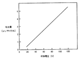
図7は、圧電素子に印加する電圧と、交流の1サイクル(周期)当たりの吐出量との関係の一例を示す図である。 FIG. 7 is a diagram illustrating an example of the relationship between the voltage applied to the piezoelectric element and the discharge amount per one cycle (period) of alternating current.
図7に示すような特性を持つ圧電素子211を用いると、例えば、交流の1サイクル(周期)あたり2.5μLの液体を吐出する場合には、圧電素子211には60Vの電圧を印加する必要がある。そのため、カートリッジ100は、100kΩの電気抵抗710と約27kΩの電気抵抗720とを備える必要がある。また、例えば、交流の1サイクル(周期)あたり1.5μLの液体を吐出する場合には、圧電素子211には40Vの電圧を印加する必要がある。そのため、カートリッジ100は、100kΩの電気抵抗710と約75kΩの電気抵抗720とを備える必要がある。また例えば、交流の1サイクル(周期)あたり4.5μLの液体を吐出する場合には、圧電素子211には100Vの電圧を印加する必要がある。そのため、カートリッジ100は、0kΩの電気抵抗710と電気抵抗720とを備える必要がある。
When the
例えば、直径が17mmの圧電素子は、60Hzに対する抵抗値が100kΩであり、100Vの電圧を印加すると1mAの電流が流れる。このように、圧電素子の電気抵抗値が大きいので、駆動電極(701、702)(図1)の間に100Vの交流電圧を印加する場合でも、駆動電極(701、702)の間には電流がわずかしか流れない。したがって、電気抵抗710と電気抵抗720の抵抗値も、比較的大きくすることができる。駆動電極(701、702)の間に印加する電圧の大きさが一定であれば、電気抵抗710と電気抵抗720の抵抗値が大きければ電気抵抗710と電気抵抗720に流れる電流が小さくなる。電気抵抗710と電気抵抗720に流れる電流が小さければ、電気抵抗710と電気抵抗720において消費される電力が少なくなる。そのため、例えば1/4W規格の電気抵抗等、小型の電気抵抗を電気抵抗710と電気抵抗720として用いることができる。このようにすることにより、カートリッジ100の製作費用を抑えることができる。また、吐出量をより少なくする場合には、圧電素子を小型にする。圧電素子を小型にすると、圧電素子の抵抗値が大きくなる。圧電素子の抵抗値が大きくなれば、分圧抵抗である電気抵抗710と電気抵抗720の抵抗値を大きくすることができる。電気抵抗710と電気抵抗720の抵抗値を大きくすることによって、電気抵抗710と電気抵抗720を流れる電流が小さくなるので、電気抵抗710と電気抵抗720において消費される電力が少なくなる。したがって、吐出量をより少なくする場合にも、小型の電気抵抗を用いることができるので、カートリッジ100の製作費用を抑えることができる。
For example, a piezoelectric element having a diameter of 17 mm has a resistance value of 100 kΩ with respect to 60 Hz, and a current of 1 mA flows when a voltage of 100 V is applied. As described above, since the electric resistance value of the piezoelectric element is large, even when an AC voltage of 100 V is applied between the drive electrodes (701, 702) (FIG. 1), a current is not generated between the drive electrodes (701, 702). Only flows slightly. Therefore, the resistance values of the
このように、電気抵抗710と電気抵抗720の抵抗値が異なるカートリッジは、同じ交流100Vの電圧を駆動電極(701、702)間に印加しても、異なる量の液体を吐出する。したがって、本体800は、それぞれのカートリッジ(カートリッジ1、カートリッジ2、カートリッジ3・・・)のタンク部100aに収容されている液体を判別して、それぞれの液体に最適な吐出量を判断する必要がなく、一定の電圧を印加するだけで、それぞれのカートリッジに固有の量の液体が吐出される。
As described above, cartridges having different resistance values of the
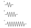
使用者は、駆動回数設定手段830を通して、芳香の強さを「弱」「標準」「強」のいずれかから選択して制御装置810に入力する。使用者によって入力された情報に基づいて、制御装置810は、1回の吐出当たりに圧電素子211に印加する交流電圧のサイクル数(周期数)を求めて、そのサイクル数(周期数)だけ交流電圧を圧電素子211に印加するように、選択手段820に制御信号を送信する。使用者によって入力された芳香の強さが「弱」「標準」「強」のとき、圧電素子211に印加される交流電圧は、それぞれ2周期、4周期、8周期である。交流電圧の周期は、圧電素子211と振動板210の振動の周期に一致する。
The user selects the intensity of the fragrance from one of “weak”, “standard”, and “strong” through the driving number setting means 830 and inputs it to the
図8は、印加する電圧が2周期の場合(A)と、4周期の場合(B)と、8周期の場合(C)の電圧を模式的に示す図である。 FIG. 8 is a diagram schematically illustrating voltages when the applied voltage is 2 cycles (A), when 4 cycles are applied (B), and when 8 cycles are applied (C).
図8に示すように、使用者が選択した芳香の強さに応じて、異なる周期の電圧が圧電素子211に印加される。
As shown in FIG. 8, voltages with different periods are applied to the
表1に、複数のカートリッジ(カートリッジ1、カートリッジ2、カートリッジ3・・・)のそれぞれについて、タンク部100aの内部に収容されている液体の種類と、振動板210と圧電素子211と電気抵抗710と電気抵抗720によって決定されている1周期当たりの吐出量と、使用者が選択した芳香の強さに応じて1回の吐出で吐出される液体の量を示す。
Table 1 shows, for each of a plurality of cartridges (

表1に示すように、カートリッジ1には、1回あたり10μLの吐出量が標準である液体が収容されており、1周期の交流電圧を印加した場合には、2.5μLの液体を吐出するように、吐出量が決定されている。カートリッジ2には、1回あたり16μLの吐出量が標準である液体が収容されており、1周期の交流電圧を印加した場合には、4μLの液体を吐出するように、吐出量が決定されている。カートリッジ3には、1回あたり6μLの吐出量が標準である液体が収容されており、1周期の交流電圧を印加した場合には、1.5μLの液体を吐出するように、吐出量が決定されている。カートリッジ4には、1回あたり4μLの吐出量が標準である液体が収容されており、1周期の交流電圧を印加した場合には、1μLの液体を吐出するように、吐出量が決定されている。カートリッジ5には、1回あたり12μLの吐出量が標準である液体が収容されており、1周期の交流電圧を印加した場合には、3μLの液体を吐出するように、吐出量が決定されている。カートリッジ6には、1回あたり2μLの吐出量が標準である液体が収容されており、1周期の交流電圧を印加した場合には、0.5μLの液体を吐出するように、吐出量が決定されている。
As shown in Table 1, the
例えば、カートリッジ1を本体800に接続した場合に、使用者が「標準」の芳香の強さを入力すると、圧電素子211には4周期の交流電圧が印加され、1周期あたり2.5μLの液体が吐出されるので4周期で10μLの液体が吐出される。一方、カートリッジ2を本体800に接続した場合に、使用者が「標準」の芳香の強さを入力すると、圧電素子211には4周期の交流電圧が印加され、1周期あたり4μLの液体が吐出されるので4周期で16μLの液体が吐出される。
For example, when the
このように、液体吐出装置の本体800は、使用者が入力した芳香の「弱」「標準」「強」の程度に応じて、2周期、4周期、8周期の100Vの交流電圧を印加するだけでよく、それぞれのカートリッジに収容されている液体が何であるかは一切関知しなくてよい。カートリッジ100側において、その内部に収容する液体に適した量を吐出するように吐出量が決定されているので、本体800の製品化の後に、必要な吐出量が異なる液を吐出する必要が生じても、その液体を収容するカートリッジ100側を変更することによって対応することができる。また、カートリッジ100ごとに自由に吐出量を調整することができるので、どのカートリッジでも一律に一定量の液体を吐出させる液体吐出装置のようにカートリッジの内部に収容する液体を薄めたりする必要なく、それぞれの液体に適した濃度の液体をカートリッジ100の内部に収容することができる。
As described above, the
このように、カートリッジ100は、液体102を収容するためのタンク部100aと、外部から与えられる駆動信号によって駆動されて、タンク部100a内の液体を外部に吐出するためのポンプ部100bとを備え、ポンプ部100bは、外部から与えられる一定の駆動信号に応じて外部に吐出する液体の量を決定する振動板210と圧電素子211と電気抵抗710と電気抵抗720を有する。
As described above, the
このようにすることにより、液体吐出装置の本体800にはタンク部100a内部に収容されている液体の種類を読み取る手段が不要となる。タンク部100aの内部に収容される液体が新しい液体であっても、液体吐出装置の本体800を、新しい液体に対応することができるように変更する必要がない。また、液体吐出装置の本体800は、タンク部100aの内部に収容されている液体の種類によって個別に吐出量の制御をする必要がないので、制御が簡単になる。
This eliminates the need for means for reading the type of liquid contained in the
さらに、液体を収容するためのタンク部100aとポンプ部100bとがカートリッジ100として一体であるので、従来のように、ポンプ部100bから吐出する液体の種類を変更する場合や、古くなって使用を続けることができなくなったカートリッジ100を別の詰替タンク部100aに交換する場合に、ポンプ部100bの内部を洗浄する必要がない。また、従来のように、液体が収容されるタンク部100aを交換した場合に、タンク部100aとポンプ部100bとの間に空気が残り、ポンプ部100b内に空気が入った状態からポンプ部100b内に液体を吸い込む自給をする必要がない。ポンプ部100b内に空気等が混入することがないので、ポンプ部100bの内部を清潔に保つことができ、吐出量が不安定になることがない。タンク部100aとポンプ部100bの内部の液体が変質して、カートリッジ100の内部において詰まりが発生した場合にも、タンク部100aとポンプ部100bとが一体に構成されているので、ポンプ部100bの内部を洗浄する必要がない。
Furthermore, since the
また、タンク部100aの内部に収容する液体に最適な材料で、それぞれのカートリッジ100のポンプ部100bを構成することができる。
Moreover, the
また、カートリッジ100を液体吐出装置の本体800に接続して直ちに液体を吐出することができる状態や、一定の駆動信号によって液体の頭出しができるようにした状態で出荷することができるので、液体を無駄にする必要がなく、不必要なにおいが発生することもない。
In addition, since the
このようにすることにより、液体吐出装置の本体800が液体の種類を判別する必要なく所定量の液体を吐出することが可能であり、吐出させる液体を簡単に交換することができるカートリッジ100を提供することができる。
In this way, it is possible to provide a
カートリッジ100においては、ポンプ部100bは、ポンプ室110と、ポンプ室110の容積を変化させるための振動板210と、振動板210を振動させるための圧電素子211とを備える。
In the
このようにすることにより、ポンプ部100bを簡単に駆動することができる。また、ポンプ部100bの製作費用を抑えることができる。
By doing in this way, the
カートリッジ100においては、外部から与えられる一定の駆動信号は、ポンプ部100bを駆動するための一定の駆動電圧であり、電気抵抗710と電気抵抗720は、外部から与えられた一定の駆動電圧をポンプ部100bに供給するための電圧に変更する電圧決定要素である。
In the
このようにすることにより、吐出量を容易に決定することができる。 In this way, the discharge amount can be easily determined.
カートリッジ100においては、電圧決定要素は、電気抵抗710と電気抵抗720を含む。このようにすることにより、電圧決定要素の製作の費用を抑えることができる。
In the
カートリッジ100においては、電圧決定要素は、昇圧回路を含んでもよい。このようにすることにより、例えば、トランスなど、簡単な回路で吐出量を決定することができる。
In the
カートリッジ100においては、吐出量決定要素は、圧電素子211と振動板210を含む。このようにすることにより、簡単に吐出量を決定することができる。
In the
また、液体吐出装置は、本体800と、本体800に接続されるカートリッジ100を備える。
In addition, the liquid ejection apparatus includes a
このようにすることにより、本体800側ではカートリッジ100内に収容されている液体の種類について判断する必要なく、簡単に、その液体に応じた量を吐出することができる。
In this way, the
(第2実施形態)
図9は、この発明の第2実施形態として、カートリッジのポンプ部の全体を示す断面図である。電気抵抗と回路は図示を省略している。
(Second Embodiment)
FIG. 9 is a cross-sectional view showing the entire pump portion of a cartridge as a second embodiment of the present invention. The electrical resistance and circuit are not shown.
図9の(A)と(B)に示すように、ポンプ部100bは、吐出量決定要素として圧電素子211aまたは圧電素子211bを備える。図9の(A)に示されるポンプ部100bが備える圧電素子211aは、図9の(B)に示されるポンプ部100bが備える圧電素子211bよりも厚みが大きい。
As shown in FIGS. 9A and 9B, the
圧電素子(211a,211b)の変位量は、原理的には圧電素子(211a,211b)の直径の2乗に比例し、厚みの2乗に反比例する。したがって、圧電素子(211a,211b)の厚みを薄くして吐出量を増加させ、圧電素子(211a,211b)の厚みを厚くして吐出量を減少させることができる。また、圧電素子(211a,211b)の直径を大きくして吐出量を増加することができ、圧電素子(211a,211b)の直径を小さくして吐出量を減少することができる。 The displacement amount of the piezoelectric elements (211a, 211b) is in principle proportional to the square of the diameter of the piezoelectric elements (211a, 211b) and inversely proportional to the square of the thickness. Accordingly, it is possible to increase the discharge amount by reducing the thickness of the piezoelectric elements (211a, 211b) and decrease the discharge amount by increasing the thickness of the piezoelectric elements (211a, 211b). Further, the discharge amount can be increased by increasing the diameter of the piezoelectric elements (211a, 211b), and the discharge amount can be decreased by decreasing the diameter of the piezoelectric elements (211a, 211b).
このように、第2実施形態のカートリッジにおいては、吐出量決定要素は、圧電素子211の材料または形状を含む。
Thus, in the cartridge of the second embodiment, the ejection amount determining element includes the material or shape of the
また、カートリッジにおいては、吐出量決定要素は、振動板210の材料または形状を含んでもよい。
In the cartridge, the discharge amount determining element may include the material or shape of the
このようにすることにより、簡単に吐出量を決定することができる。 In this way, the discharge amount can be easily determined.
第2実施形態のポンプ部100bとカートリッジのその他の構成と効果は、第1実施形態のポンプ部100bとカートリッジ100と同様である。
Other configurations and effects of the
(第3実施形態)
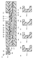
図10は、この発明の第3実施形態として、カートリッジのポンプ部の全体を示す図(A)と、吐出側逆止弁と吐出側弁座の上面とを示す図((B)と(C))である。電気抵抗と回路は図示を省略している。
(Third embodiment)
FIG. 10 shows, as a third embodiment of the present invention, a diagram (A) showing the entire pump portion of a cartridge, and a diagram ((B) and (C) showing a discharge side check valve and a top surface of a discharge side valve seat. )). The electrical resistance and circuit are not shown.
図10の(A)に示すように、第3実施形態の液体吐出装置用詰替容器としてのカートリッジにおいては、吐出量決定要素は、吸入口310と吐出口320の径の大きさである。図1に示す第1実施形態のポンプ部100bと第3実施形態のポンプ部100bとを比較すると、第3実施形態のポンプ部100bにおいては、吸入口310と吐出口320の径が、それぞれ、第1実施形態のポンプ部100bの吸入口310と吐出口320の径よりも小さい。
As shown in FIG. 10A, in the cartridge as the refill container for the liquid ejection device according to the third embodiment, the ejection amount determination factor is the size of the diameters of the
図10の(B)と(C)に示すように、吐出口320aと吐出口320bは径の大きさが異なる。このように、吐出口320および吸入口310の径の大きさが異なることによって、ポンプ部100bの吐出端203から吐出される液体の量が異なる。それぞれのカートリッジにおいては、内部に収容される液体に応じて最適な量が吐出されるように、吐出口320および吸入口310の径の大きさを決定することができる。
As shown in FIGS. 10B and 10C, the
このように、第3実施形態のカートリッジは、タンク部100aからポンプ室110に液体を吸入するための吸入口310と、吸入口310において液体の流れを調節するための吸入側逆止弁500と、ポンプ室110の内部からポンプ室110の外部に液体を吐出する吐出口320と、吐出口320において液体の流れを調節するための吐出側逆止弁600と備え、吐出量決定要素は、吸入口310および/または吐出口320の径の大きさである。
As described above, the cartridge according to the third embodiment includes the
このようにすることにより、簡単に吐出量を決定することができる。 In this way, the discharge amount can be easily determined.
第3実施形態のポンプ部100bとカートリッジのその他の構成と効果は、第1実施形態のポンプ部100bとカートリッジ100と同様である。
Other configurations and effects of the
(第4実施形態)
図11は、この発明の第4実施形態として、カートリッジのポンプ部の全体を示す断面図である。電気抵抗と回路は図示を省略している。
(Fourth embodiment)
FIG. 11 is a cross-sectional view showing the entire pump portion of a cartridge as a fourth embodiment of the present invention. The electrical resistance and circuit are not shown.
図11の(A)と(B)に示すように、ポンプ部100bにおいては、吐出量決定要素は、吸入側逆止弁500と吐出側逆止弁600の硬さを含む。図11の(A)に示されるポンプ部100bが備える吸入側逆止弁500の頭部501aと吐出側逆止弁600の頭部601aは、それぞれ、図11の(B)に示されるポンプ部100bが備える吸入側逆止弁500の頭部501bと吐出側逆止弁600の頭部601bよりも厚みが厚く、硬く形成されている。
As shown in FIGS. 11A and 11B, in the
厚く、硬い逆止弁を備えることによって、圧電素子211に一定の駆動電圧を印加されても、逆止弁の頭部(501a、601a)が動きにくくなり、カートリッジから吐出される液体の量が小さくなる。一方、薄く、柔らかい逆止弁を備えることによって、圧電素子211に一定の駆動電圧を印加されても、逆止弁の頭部(501b、601b)が動きやすくなり、カートリッジから吐出される液体の量が大きくなる。
By providing a thick and hard check valve, the head (501a, 601a) of the check valve does not move easily even when a constant drive voltage is applied to the
このように、第4実施形態のカートリッジは、タンク部100aからポンプ室110に液体を吸入するための吸入口310と、吸入口310において液体の流れを調節するための吸入側逆止弁501と、ポンプ室110の内部からポンプ室110の外部に液体を吐出する吐出口320と、吐出口320において液体の流れを調節するための吐出側逆止弁600と備え、吐出量決定要素は、吸入側逆止弁500および吐出側逆止弁600の硬さである。
As described above, the cartridge according to the fourth embodiment includes the
このようにすることにより、簡単に吐出量を決定することができる。 In this way, the discharge amount can be easily determined.
第4実施形態のポンプ部100bとカートリッジのその他の構成と効果は、第1実施形態のポンプ部100bとカートリッジ100と同様である。
Other configurations and effects of the
(第5実施形態)
図12は、この発明の第5実施形態として、カートリッジのポンプ部の全体を示す断面図である。電気抵抗と回路は図示を省略している。
(Fifth embodiment)
FIG. 12 is a cross-sectional view showing the entire pump portion of a cartridge as a fifth embodiment of the present invention. The electrical resistance and circuit are not shown.
図12の(A)と(B)に示すように、ポンプ部100bにおいては、吐出量決定要素は、吐出管202の内壁に形成された突起(201a、201b)によって吐出側逆止弁600が吐出側弁座(400a、400b)に押圧されるときの押圧の大きさを含む。
As shown in FIGS. 12A and 12B, in the
突起201aは、突起201bよりも厚みが大きく、吐出側逆止弁600を強く押圧する。また、吐出側弁座400aの上面の形状は、球の内面状の傾斜を有するが、吐出側弁座400bの上面の形状は、吐出側弁座400aの上面の傾斜とは異なる傾斜を有する。このように、突起(201a、201b)と吐出側弁座(400a、400b)の形状がポンプ部100bによって異なることによって、図12の(A)に示すポンプ部100bと図12の(B)に示すポンプ部100bとでは、吐出側逆止弁600が押圧されるときの押圧の量が異なる。
The
このように、第5実施形態のカートリッジは、吐出口320が形成される吐出側弁座400を備え、吐出側逆止弁600は、吐出側弁座400に押圧されて、吐出口320を閉塞することが可能であるように構成され、吐出量決定要素は、吐出側逆止弁600が突起201と吐出側弁座400に押圧されるときの押圧の大きさを含む。
As described above, the cartridge of the fifth embodiment includes the discharge
このようにすることにより、簡単に吐出量を決定することができる。 In this way, the discharge amount can be easily determined.
また、このように、第5実施形態のカートリッジにおいては、吐出量決定要素は、吐出側弁座400の形状を含む。
As described above, in the cartridge of the fifth embodiment, the discharge amount determining element includes the shape of the discharge
このようにすることにより、簡単に吐出量を決定することができる。 In this way, the discharge amount can be easily determined.
第5実施形態のポンプ部100bとカートリッジのその他の構成と効果は、第1実施形態のポンプ部100bとカートリッジ100と同様である。
Other configurations and effects of the
(第6実施形態)
図13は、この発明の第6実施形態として、カートリッジのポンプ部の全体を示す断面図(A)と、吐出端に取り付けられる蓋の断面を示す図((B)〜(E))である。電気抵抗と回路は図示を省略している。
(Sixth embodiment)
FIG. 13 is a cross-sectional view (A) showing the entire pump portion of the cartridge and views ((B) to (E)) showing a cross-section of a lid attached to the discharge end as a sixth embodiment of the present invention. . The electrical resistance and circuit are not shown.
図13の(A)に示すように、第6実施形態のポンプ部100bの吐出端203には、吐出量決定要素として蓋740が取り付けられている。吐出端203は、蓋740によって覆われている。蓋740には蓋740を貫通する流路として孔741が形成されており、吐出端203と外部は孔741によって連通されている。ポンプ室110から吐出口320を通って吐出管202に吐出される液体は、吐出端203から蓋740に形成された孔741を通って、外部に吐出される。
As shown to (A) of FIG. 13, the
図13の(B)〜(E)に示すように、それぞれ孔(741a、741b、741c、741d)の径が異なる蓋(740a、740b、740c、740d)を吐出端203に取り付けることによって、孔(741a、741b、741c、741d)から吐出される液体の量を決定することができる。
As shown in FIGS. 13B to 13E, by attaching lids (740a, 740b, 740c, 740d) having different diameters of the holes (741a, 741b, 741c, 741d) to the
このように、第6実施形態のカートリッジは、液体を流通するための蓋(740a、740b、740c、740d)の孔(741a、741b、741c、741d)を備え、吐出量決定要素は、孔(741a、741b、741c、741d)の径を含む。 Thus, the cartridge of the sixth embodiment includes the holes (741a, 741b, 741c, 741d) of the lids (740a, 740b, 740c, 740d) for circulating the liquid, and the discharge amount determining element is the hole ( 741a, 741b, 741c, 741d).
このようにすることにより、簡単に吐出量を決定することができる。 In this way, the discharge amount can be easily determined.
第6実施形態のポンプ部100bとカートリッジのその他の構成と効果は、第1実施形態のポンプ部100bとカートリッジ100と同様である。
Other configurations and effects of the
(第7実施形態)
図14は、この発明の第7実施形態として、カートリッジのポンプ部の全体を示す断面である。電気抵抗と回路は図示を省略している。
(Seventh embodiment)
FIG. 14 is a sectional view showing the entire pump portion of a cartridge as a seventh embodiment of the present invention. The electrical resistance and circuit are not shown.
図14の(A)と(B)に示すように、第7実施形態のカートリッジのポンプ部100bにおいては、吐出量決定要素はポンプ室110の容積を含む。
As shown in FIGS. 14A and 14B, in the
図14の(A)に示されるポンプ部100bと図14の(B)に示されるポンプ部100bとを比較すると、図14の(B)に示されるポンプ部100bは、容積変更部材730がポンプ室110内に配置されてポンプ室110の容積が小さくなっている。
Comparing the
ポンプ室110の容積が変化すると、吐出端203から吐出される液体の量が変化する。例えば、ポンプ室110の容積が66μLのポンプ部100bよりも、容積変更部材730を配置してポンプ室110の容積を47μLと小さくしたポンプ部100bの方が、吐出量は大きくなる。このように、ポンプ室110の容積を変更することで、流量調整を行なって吐出量に調整することが可能である。但し、液体の吐出量の変化は単純にポンプ室110の容積によって変化するだけでなく、ポンプ室110の構造によっても変化する。
When the volume of the
このように、第7実施形態のカートリッジにおいては、吐出量決定要素は、ポンプ室110の容積を含む。
Thus, in the cartridge of the seventh embodiment, the discharge amount determining element includes the volume of the
また、第7実施形態のカートリッジにおいては、吐出量決定要素は、ポンプ室110の容積を変更するための容積変更部材730を含む。
Further, in the cartridge of the seventh embodiment, the discharge amount determining element includes a
このようにすることにより、簡単に吐出量を決定することができる。 In this way, the discharge amount can be easily determined.
第7実施形態のポンプ部100bとカートリッジのその他の構成と効果は、第1実施形態のポンプ部100bとカートリッジ100と同様である。
Other configurations and effects of the
以上の第1から第7実施形態においては、タンク部100aの詳細な構成については記載していないが、タンク部100aの内部には、液体のみがそのまま充填されていても、スポンジが配置されていてもよい。
In the first to seventh embodiments described above, the detailed configuration of the
また、ポンプ部100bは、圧電素子211で駆動するものでなくても、電気抵抗の分圧や、ポンプ室110や流路の形状等で流量を変更できるものであればよい。
Further, the
本発明の液体吐出装置用詰替容器において、吐出量決定要素による吐出量の決定について説明する。 In the refill container for a liquid ejection device according to the present invention, the determination of the ejection amount by the ejection amount determining element will be described.
まず、液体吐出装置用詰替容器としては、図1に示す第1実施形態のカートリッジ100の構成のカートリッジについて、圧電素子211の直径と、圧電素子211の厚みと、圧電素子211に印加する電圧と、吸入口310の径と、吐出口320の径を変化させた3種類のカートリッジを用いて、圧電素子211に印加する交流電圧の1サイクル当たりの吐出量の変化を調べた。
First, as a refill container for a liquid ejection device, the diameter of the
カートリッジ100は、吸入口310と吐出口320をそれぞれ6個ずつ有する。吐出側逆止弁600が取り付けられる吐出側弁座400の上面401は平坦であった。吐出側逆止弁600は、硬度40、頭部601の周辺厚みを0.5mmとした。吸入側逆止弁500は、硬度40、頭部501の周辺厚みを0.3mmとした。吸入側逆止弁500と吐出側逆止弁600の硬度は、ジュロメータ硬さで表した硬度である。
The
図15は、吐出量決定要素として圧電素子の直径と、厚みと、印加する電圧と、吸入口と吐出口の径を変化させた場合の吐出量の変化を示す図である。 FIG. 15 is a diagram showing changes in the discharge amount when the diameter, thickness, voltage to be applied, and the diameters of the suction port and the discharge port are changed as the discharge amount determining element.
図15に示すように、吸入口310と吐出口320の径が1.2mm(Φ1.2mm))であるとき、圧電素子の直径が17mm、厚みが0.3mm、電気抵抗710と電気抵抗720とによって変更されて圧電素子211に印加される電圧が80Vのカートリッジでは、交流電圧1サイクル当たりの吐出量は3.5μLであった。また、圧電素子の直径が17mm、厚みが0.55mm、電気抵抗710と電気抵抗720とによって変更されて圧電素子211に印加される電圧が100Vのカートリッジでは、交流電圧1サイクル当たりの吐出量は1.5μLであった。圧電素子の直径が9mm、厚みが0.45mm、電気抵抗710と電気抵抗720とによって変更されて圧電素子211に印加される電圧が60Vのカートリッジでは、交流電圧1サイクル当たりの吐出量は0.6μLであった。なお、電圧は、それぞれの圧電素子の特性や厚みから推奨される代表値を印加した。
As shown in FIG. 15, when the diameters of the
また、例えば、圧電素子の直径が17mm、厚みが0.3mm、電気抵抗710と電気抵抗720とによって変更されて圧電素子211に印加される電圧が80Vのカートリッジでは、吸入口310と吐出口320の径を1.2mmとした場合には、印加する交流電圧の1サイクル当たり3.5μLの吐出量となり、吸入口310と吐出口320の径を0.8mmとした場合には、印加する交流電圧の1サイクル当たり1.6μLの吐出量となった。
Further, for example, in a cartridge in which the piezoelectric element has a diameter of 17 mm, a thickness of 0.3 mm, an
また、例えば、圧電素子の直径が17mm、厚みが0.55mm、電気抵抗710と電気抵抗720とによって変更されて圧電素子211に印加される電圧が100Vのカートリッジでは、吸入口310と吐出口320の径を1.2mmとした場合には、印加する交流電圧の1サイクル当たり1.5μLの吐出量となり、吸入口310と吐出口320の径を0.8mmとした場合には、印加する交流電圧の1サイクル当たり1.0μLの吐出量となった。
Further, for example, in a cartridge in which the diameter of the piezoelectric element is 17 mm, the thickness is 0.55 mm, and the voltage applied to the
また、吐出側逆止弁600が取り付けられる吐出側弁座400の上面をすり鉢状にして、吐出側逆止弁600と吐出側弁座400との密着度を上げて押さえを強くして、硬度30で柔らかく、周辺厚み0.5mmの吐出側逆止弁600を用い、硬度40、周辺厚み0.3mmの吸入側逆止弁500を用いた場合の吐出量は、印加した交流電圧の1サイクル当たり3μLであった。吸入側逆止弁500と吐出側逆止弁600の硬度は、ジュロメータ硬さで表した硬度である。
In addition, the upper surface of the discharge
また、このとき、ポンプ部100bの吐出端203に直径0.6mmの穴741を開けた蓋740(図13)を使用した場合、印加した交流電圧の1サイクルあたりの吐出量は1μLであった。
At this time, when a lid 740 (FIG. 13) having a
以上の実施例に示したグラフやデータは一例であり、各ポンプの構造、材質、大きさによって、吐出量の変化の度合いは異なる。 The graphs and data shown in the above embodiments are examples, and the degree of change in the discharge amount varies depending on the structure, material, and size of each pump.
以上に開示された実施の形態と実施例はすべての点で例示であって制限的なものではないと考慮されるべきである。本発明の範囲は、以上の実施の形態と実施例ではなく、特許請求の範囲によって示され、特許請求の範囲と均等の意味および範囲内でのすべての修正と変形を含むものである。 It should be considered that the embodiments and examples disclosed above are illustrative and non-restrictive in every respect. The scope of the present invention is shown not by the above-described embodiments and examples but by the scope of claims, and includes all modifications and variations within the meaning and scope equivalent to the scope of claims.
100:カートリッジ、100a:タンク部、100b:ポンプ部、110:ポンプ室、200:吸入吐出側ケース、201,201a,201b:突起、202:吐出管、210:振動板、211,211a,211b:圧電素子、300:ハウジング、310:吸入口、320,320a,320b:吐出口、330:吸入側弁座、400:吐出側弁座、401:凹面、500:吸入側逆止弁、501,501a,501b:頭部、600:吐出側逆止弁、601,601a,601b:頭部、710,720:電気抵抗、730:容積変更部材、740,740a,740b,740c,740d:蓋、741,741a,741b,741b,741c,741d:孔。 100: cartridge, 100a: tank section, 100b: pump section, 110: pump chamber, 200: suction / discharge side case, 201, 201a, 201b: protrusion, 202: discharge pipe, 210: diaphragm, 211, 211a, 211b: Piezoelectric element, 300: housing, 310: suction port, 320, 320a, 320b: discharge port, 330: suction side valve seat, 400: discharge side valve seat, 401: concave surface, 500: suction side check valve, 501 and 501a , 501b: head, 600: discharge side check valve, 601, 601a, 601b: head, 710, 720: electrical resistance, 730: volume changing member, 740, 740a, 740b, 740c, 740d: lid, 741, 741a, 741b, 741b, 741c, 741d: holes.
Claims (6)
外部から与えられる駆動信号によって駆動されて、前記容器内の液体を外部に吐出するためのポンプとを備え、
前記ポンプは、ポンプ室と、外部から与えられる一定の駆動信号に応じて外部に吐出する量を決定する吐出量決定要素とを有し、
外部から与えられる一定の前記駆動信号は、前記ポンプを駆動するための一定の交流駆動電圧を有する駆動信号であり、
前記吐出量決定要素は、外部から与えられた一定の前記駆動信号の交流駆動電圧を前記ポンプに供給するための電圧に変更する電圧決定要素と、前記ポンプ室の容積を変化させるための振動板と、前記振動板を振動させるための圧電素子とを含み、
前記駆動信号において所要のサイクル数を選択することによって、前記圧電素子に供給される電力を調整する選択手段をさらに備えた、液体吐出装置用カートリッジ。 A container for containing the liquid;
A pump that is driven by a driving signal given from the outside and discharges the liquid in the container to the outside;
The pump, possess a pump chamber, a discharge amount determination factor in determining the amount to be ejected to the outside in accordance with a constant drive signal given from the outside,
The constant driving signal given from the outside is a driving signal having a constant AC driving voltage for driving the pump,
The discharge amount determining element includes a voltage determining element for changing an AC driving voltage of the constant driving signal given from the outside to a voltage for supplying the pump, and a diaphragm for changing the volume of the pump chamber And a piezoelectric element for vibrating the diaphragm,
A cartridge for a liquid ejection apparatus , further comprising selection means for adjusting electric power supplied to the piezoelectric element by selecting a required number of cycles in the drive signal .
請求項1に記載の液体吐出装置用カートリッジ。The cartridge for a liquid ejection device according to claim 1.
請求項1または請求項2に記載の液体吐出装置用カートリッジ。The cartridge for a liquid ejection device according to claim 1 or 2.
前記吸入口において液体の流れを調節するための吸入側逆止弁と、A suction-side check valve for adjusting the flow of liquid at the suction port;
前記ポンプ室の内部から前記ポンプ室の外部に液体を吐出する吐出口と、A discharge port for discharging liquid from the inside of the pump chamber to the outside of the pump chamber;
前記吐出口において液体の流れを調節するための吐出側逆止弁とをさらに備え、A discharge-side check valve for adjusting the flow of liquid at the discharge port,
前記吐出量決定要素は、ジュロメータ硬さで表した硬度である前記吸入側逆止弁および/または前記吐出側逆止弁の硬さを含む、The discharge amount determining element includes the hardness of the suction side check valve and / or the discharge side check valve, which is a hardness expressed in durometer hardness,
請求項1から請求項3までのいずれか1項に記載の液体吐出装置用カートリッジ。The cartridge for a liquid ejection device according to any one of claims 1 to 3.
前記吸入口において液体の流れを調節するための吸入側逆止弁と、A suction-side check valve for adjusting the flow of liquid at the suction port;
前記ポンプ室の内部から前記ポンプ室の外部に液体を吐出する吐出口と、A discharge port for discharging liquid from the inside of the pump chamber to the outside of the pump chamber;
前記吐出口において液体の流れを調節するための吐出側逆止弁と、A discharge-side check valve for adjusting the flow of liquid at the discharge port;
前記吸入口および/または前記吐出口が形成される壁部とをさらに備え、A wall portion on which the suction port and / or the discharge port are formed,
前記吸入側逆止弁および/または前記吐出側逆止弁は、前記壁部に押圧されて、それぞれ、前記吸入口および/または前記吐出口を閉塞することが可能であるように構成され、The suction-side check valve and / or the discharge-side check valve are configured to be pressed by the wall portion so as to close the suction port and / or the discharge port, respectively.
前記吐出量決定要素は、前記吸入側逆止弁および/または前記吐出側逆止弁が前記壁部に押圧されるときの押圧の大きさを含む、The discharge amount determining element includes a magnitude of pressing when the suction side check valve and / or the discharge side check valve is pressed against the wall portion.
請求項1から請求項4までのいずれか1項に記載の液体吐出装置用カートリッジ。The cartridge for a liquid ejection device according to any one of claims 1 to 4.
前記本体に接続される、請求項1から請求項5までのいずれか1項に記載の液体吐出装置用カートリッジとを備えた、液体吐出装置。 The body,
A liquid ejection apparatus comprising: the liquid ejection apparatus cartridge according to claim 1, which is connected to the main body.
Priority Applications (1)
| Application Number | Priority Date | Filing Date | Title |
|---|---|---|---|
| JP2007125846A JP5014872B2 (en) | 2007-05-10 | 2007-05-10 | Liquid discharge device cartridge and liquid discharge device including the same |
Applications Claiming Priority (1)
| Application Number | Priority Date | Filing Date | Title |
|---|---|---|---|
| JP2007125846A JP5014872B2 (en) | 2007-05-10 | 2007-05-10 | Liquid discharge device cartridge and liquid discharge device including the same |
Publications (3)
| Publication Number | Publication Date |
|---|---|
| JP2008279367A JP2008279367A (en) | 2008-11-20 |
| JP2008279367A5 JP2008279367A5 (en) | 2009-12-03 |
| JP5014872B2 true JP5014872B2 (en) | 2012-08-29 |
Family
ID=40140649
Family Applications (1)
| Application Number | Title | Priority Date | Filing Date |
|---|---|---|---|
| JP2007125846A Expired - Fee Related JP5014872B2 (en) | 2007-05-10 | 2007-05-10 | Liquid discharge device cartridge and liquid discharge device including the same |
Country Status (1)
| Country | Link |
|---|---|
| JP (1) | JP5014872B2 (en) |
Cited By (1)
| Publication number | Priority date | Publication date | Assignee | Title |
|---|---|---|---|---|
| US11766528B2 (en) | 2019-11-27 | 2023-09-26 | L'oreal | Selective sealing cartridge |
Families Citing this family (2)
| Publication number | Priority date | Publication date | Assignee | Title |
|---|---|---|---|---|
| AU2009308624B2 (en) | 2008-10-30 | 2013-04-18 | Oji Holdings Corporation | Sugar production process and ethanol production process |
| US10759554B2 (en) * | 2017-02-02 | 2020-09-01 | Rai Strategic Holdings, Inc. | Dispenser unit for aerosol precursor |
Family Cites Families (3)
| Publication number | Priority date | Publication date | Assignee | Title |
|---|---|---|---|---|
| US4500895A (en) * | 1983-05-02 | 1985-02-19 | Hewlett-Packard Company | Disposable ink jet head |
| JP3402910B2 (en) * | 1996-03-13 | 2003-05-06 | キヤノン株式会社 | Ink jet recording head, ink jet recording head cartridge and ink jet recording apparatus |
| JP2005224503A (en) * | 2004-02-16 | 2005-08-25 | Canon Semiconductor Equipment Inc | Device for jetting fragrance or the like |
-
2007
- 2007-05-10 JP JP2007125846A patent/JP5014872B2/en not_active Expired - Fee Related
Cited By (1)
| Publication number | Priority date | Publication date | Assignee | Title |
|---|---|---|---|---|
| US11766528B2 (en) | 2019-11-27 | 2023-09-26 | L'oreal | Selective sealing cartridge |
Also Published As
| Publication number | Publication date |
|---|---|
| JP2008279367A (en) | 2008-11-20 |
Similar Documents
| Publication | Publication Date | Title |
|---|---|---|
| EP1053879B1 (en) | Liquid consumption status detecting method, liquid container, and ink cartridge | |
| JP6362008B2 (en) | Pump system and pump abnormality detection method | |
| JP5064735B2 (en) | How to select liquid dispensing parameters | |
| US6675646B2 (en) | Liquid-quantity monitoring apparatus and liquid-consuming apparatus with the same | |
| JP5014872B2 (en) | Liquid discharge device cartridge and liquid discharge device including the same | |
| US9452442B2 (en) | Electronic spray device improvements | |
| US10653178B1 (en) | Method and apparatus for an aerosol generation device | |
| US20110114750A1 (en) | Piezoelectric spraying system and corresponding refill | |
| US6581852B2 (en) | Fluid dispenser | |
| JP2008089181A (en) | Minute amount distribution device for liquid medium | |
| JP2002154223A (en) | Liquid consumption state detector | |
| JP4150158B2 (en) | Liquid consumption state detector | |
| JP4794401B2 (en) | Micropump and sustained release device equipped with the same | |
| JP2005207898A (en) | Liquid surface detector and dispenser using the same | |
| JP4655283B2 (en) | Liquid consumption state detector | |
| JP2011094846A (en) | Spray device | |
| JP4656062B2 (en) | Detection control circuit | |
| JP2005241263A (en) | Liquid discharge head | |
| JP4150157B2 (en) | Liquid consumption state detector | |
| JP2006341585A (en) | Vessel equipped with liquid detecting function | |
| JP2006343337A (en) | Liquid consumption state detector | |
| JP2004066616A (en) | Printer and method for detecting ink remaining amount | |
| JP2015004645A (en) | Oxygen concentration measurement device | |
| JP2002156268A (en) | Liquid consumption state detector | |
| JP4763767B2 (en) | Polymer container for electrophoresis |
Legal Events
| Date | Code | Title | Description |
|---|---|---|---|
| A521 | Written amendment |
Free format text: JAPANESE INTERMEDIATE CODE: A523 Effective date: 20091021 |
|
| A621 | Written request for application examination |
Free format text: JAPANESE INTERMEDIATE CODE: A621 Effective date: 20091021 |
|
| A977 | Report on retrieval |
Free format text: JAPANESE INTERMEDIATE CODE: A971007 Effective date: 20110908 |
|
| A131 | Notification of reasons for refusal |
Free format text: JAPANESE INTERMEDIATE CODE: A131 Effective date: 20111115 |
|
| A521 | Written amendment |
Free format text: JAPANESE INTERMEDIATE CODE: A523 Effective date: 20120113 |
|
| TRDD | Decision of grant or rejection written | ||
| A01 | Written decision to grant a patent or to grant a registration (utility model) |
Free format text: JAPANESE INTERMEDIATE CODE: A01 Effective date: 20120515 |
|
| A01 | Written decision to grant a patent or to grant a registration (utility model) |
Free format text: JAPANESE INTERMEDIATE CODE: A01 |
|
| A61 | First payment of annual fees (during grant procedure) |
Free format text: JAPANESE INTERMEDIATE CODE: A61 Effective date: 20120606 |
|
| FPAY | Renewal fee payment (event date is renewal date of database) |
Free format text: PAYMENT UNTIL: 20150615 Year of fee payment: 3 |
|
| R150 | Certificate of patent or registration of utility model |
Free format text: JAPANESE INTERMEDIATE CODE: R150 |
|
| LAPS | Cancellation because of no payment of annual fees |