JP5014076B2 - Ink tank - Google Patents
Ink tank Download PDFInfo
- Publication number
- JP5014076B2 JP5014076B2 JP2007295690A JP2007295690A JP5014076B2 JP 5014076 B2 JP5014076 B2 JP 5014076B2 JP 2007295690 A JP2007295690 A JP 2007295690A JP 2007295690 A JP2007295690 A JP 2007295690A JP 5014076 B2 JP5014076 B2 JP 5014076B2
- Authority
- JP
- Japan
- Prior art keywords
- absorber
- ink
- structural body
- absorbent body
- ink tank
- Prior art date
- Legal status (The legal status is an assumption and is not a legal conclusion. Google has not performed a legal analysis and makes no representation as to the accuracy of the status listed.)
- Expired - Fee Related
Links
Images


Description
本発明は、インクジェットプリンターに搭載されるインクカートリッジにて使用されるインクを貯蔵するためのインクタンクおよびその製造方法に関する。 The present invention relates to an ink tank for storing ink used in an ink cartridge mounted on an ink jet printer, and a manufacturing method thereof.
現在市販されているインクジェットプリンターに搭載されるインクカートリッジのインク容量は、市場調査等の結果をフィードバックし、より市場ニーズに合ったインクジェットプリンターの仕様を満足するように決められている。 The ink capacity of ink cartridges mounted on currently marketed inkjet printers is determined so as to satisfy the specifications of inkjet printers that better meet market needs by feeding back the results of market research and the like.
一方、インクカートリッジは、消耗品であり生産数が非常に多いため、市場ニーズの全てに対応しようとすれば、各種インク量のバリエーションが必要となる。 On the other hand, since ink cartridges are consumables and are produced in large quantities, various ink amounts are required to meet all market needs.
しかし、多品種少量生産は、大量生産には向かず、また生産コストもかかってしまうため、インクカートリッジの価格が高くなってしまう。そうすると、インクカートリッジの商品性が低下する可能性がある。 However, the high-mix low-volume production is not suitable for mass production and costs high, and the price of the ink cartridge becomes high. If it does so, the commercial property of an ink cartridge may fall.
このため、今後、インクカートリッジは、大量生産を前提とし、ライン上の都合から、サイズや形状をある程度絞り込んで、ベーシックにする必要がある。 For this reason, in the future, it is necessary to make the ink cartridge basic by narrowing down the size and shape to some extent from the convenience of the line on the premise of mass production.
このような背景の下でも、インクカートリッジにおいては、出荷国やインクジェットプリンターの仕様に合わせて、やむを得ずインク量を変える場合があり、インク量を常に一定にしておくことは困難である。 Even in such a background, in the ink cartridge, the ink amount may be unavoidably changed according to the shipping country and the specifications of the ink jet printer, and it is difficult to keep the ink amount constant.
インクカートリッジのインク量を変える場合、既存カートリッジのインク量に対して減らす場合と増やす場合がある。 When the ink amount of the ink cartridge is changed, the ink amount of the existing cartridge may be reduced or increased.
既存カートリッジに対してインク量を減らす場合は、現状よりもインク注入量を減らすだけで対応することができる。 When the ink amount is reduced with respect to the existing cartridge, it can be dealt with by merely reducing the ink injection amount as compared with the current state.
しかし、既存カートリッジに対してインク量を増やす場合は、そのままインク注入量を増やすだけでは信頼性が保証できなくなり、最悪の場合はインク漏れが発生する可能性もあるため、容易には対応することができない。 However, when increasing the ink amount relative to the existing cartridge, it is not possible to guarantee reliability by simply increasing the ink injection amount as it is, and in the worst case ink leakage may occur. I can't.
そのため、既存カートリッジに対してインク量を増やす場合は、その都度、インクカートリッジのインクタンク、吸収体、その周辺部品等の検討・再設計を行い、試作型を新規製作して試作・評価を行う必要がある。 Therefore, whenever the amount of ink is increased relative to the existing cartridge, the ink tank, the absorber, and the peripheral parts of the ink cartridge are examined and redesigned each time, and a prototype is newly manufactured and prototyped and evaluated. There is a need.
しかし、既存カートリッジに対してインク量を増やす場合に、その都度、インクカートリッジの検討・再設計・試作・評価を行うことは、多大な開発費用と時間を要するため、昨今、開発期間の短縮化が求められている中、相反する課題となっていた。 However, every time you increase the amount of ink compared to an existing cartridge, it takes a lot of development cost and time to examine, redesign, prototype, and evaluate the ink cartridge. Has been a conflicting issue.
このような状況において、既存カートリッジをそのまま流用して容易にインク量を増量できる構成は、各種インク量のバリエーションにも対応可能であり、市場ニーズにも容易かつ迅速に対応することができる。 In such a situation, the configuration that can easily increase the ink amount by diverting the existing cartridge as it is, can cope with variations in various ink amounts, and can easily and quickly respond to market needs.
そのような構成は、特許文献1に開示されている。特許文献1では、インクカートリッジのインクタンクを2つの構成体を連結した構成としている。そして、2つの構成体のそれぞれに対し、吸収体挿入開口部からはみ出すように吸収体を挿入し、これらの吸収体が圧縮された状態で接触するように、2つの構成体同士を連結している。
しかし、特許文献1に開示された構成では、2つの構成体同士を超音波溶着等で連結する際に、それぞれの構成体の吸収体挿入開口部からはみ出た吸収体を、溶着連結面で挟み込んでしまうという課題があった。仮に、吸収体のはみ出し量を精度よく管理したとしても、吸収体同士が接触する際には吸収体が圧縮されて横に広がるため、少なからず溶着連結面では吸収体を挟み込んでしまう。 However, in the configuration disclosed in Patent Document 1, when two components are connected to each other by ultrasonic welding, the absorber protruding from the absorber insertion opening of each component is sandwiched between the welding connection surfaces. There was a problem of getting out. Even if the amount of protrusion of the absorber is accurately controlled, the absorber is compressed and spreads laterally when the absorbers come into contact with each other, so that the absorber is sandwiched between the welding connection surfaces.
また、溶着方法としては、超音波溶着以外にも、より強固に連結し得る振動溶着という方法もある。しかし、振動溶着は、2つの構成体同士を相対的に1mm〜2mm程度移動させる(これを振動溶着時の振幅と呼ぶ)ことで発生する摩擦熱により接合するため、上述の超音波溶着に比べると、溶着の際の移動時に吸収体を挟み込みやすくなる。 In addition to ultrasonic welding, there is also a method called vibration welding that can be more firmly connected. However, since vibration welding is performed by frictional heat generated by moving two components relative to each other by about 1 mm to 2 mm (this is referred to as amplitude during vibration welding), it is compared with the ultrasonic welding described above. And it becomes easy to insert | pinch an absorber at the time of the movement in the case of welding.
そこで、本発明の目的は、2つの構成体同士を連結する際に、吸収体の挟み込みを防ぐことができるインクタンクおよびその製造方法を提供することにある。 SUMMARY OF THE INVENTION Accordingly, an object of the present invention is to provide an ink tank and a method for manufacturing the same that can prevent the absorber from being caught when two components are connected to each other.
上記目的を達成するために本発明のインクタンクは、
インクを保持する第1および第2の吸収体をそれぞれ収容する第1および第2の構成体を備え、前記第1の吸収体と前記第2の吸収体とが接触するように前記第1の構成体と前記第2の構成体とが連結されたインクタンクであって、
前記第1の吸収体は、前記第1の構成体と前記第2の構成体との連結方向において、前記第1の吸収体が前記第1の構成体の吸収体挿入開口から外側にはみ出さないように挿入され、
前記第2の吸収体は、前記第1の構成体と前記第2の構成体との連結方向において、前記第2の吸収体が前記第2の構成体の吸収体挿入開口から外側にはみ出すように挿入され、
前記第2の吸収体における前記第1の吸収体と対向する面のサイズは、当該面が前記第1の吸収体における前記第2の吸収体と対向する面の内側に収まるようなサイズであり、
前記第1の構成体と前記第2の構成体とは振動溶着により連結され、前記振動溶着時の移動方向において、前記第2の吸収体における前記第1の吸収体と対向する面の淵と、前記第1の吸収体における前記第2の吸収体と対向する面の淵と、の間の距離は、前記振動溶着時の振幅よりも大きいことを特徴とする。
In order to achieve the above object, the ink tank of the present invention comprises:
A first and a second structural body for accommodating first and second absorbers for holding ink, respectively, wherein the first absorber and the second absorber are in contact with each other; An ink tank in which a structure and the second structure are connected,
The first absorbent body protrudes outward from the absorbent body insertion opening of the first structural body in the connecting direction of the first structural body and the second structural body. Inserted so that there is no
The second absorbent body protrudes outward from the absorbent body insertion opening of the second structural body in the connecting direction of the first structural body and the second structural body. Inserted into
The size of the surface of the second absorber facing the first absorber is such that the surface fits inside the surface of the first absorber facing the second absorber. ,
The first structural body and the second structural body are coupled by vibration welding, and a ridge on a surface of the second absorbent body facing the first absorbent body in a moving direction at the time of vibration welding. The distance between the surface of the first absorbent body facing the second absorbent body is larger than the amplitude at the time of vibration welding .
以上説明したように、本発明のインクタンクによれば、第1の構成体が、吸収体挿入開口から第1の吸収体を内部に押し込むように構成されているため、第2の構成体との連結時に、第2の吸収体の挟み込みを防止することができるという効果が得られる。 As described above, according to the ink tank of the present invention, since the first component is configured to push the first absorber into the interior through the absorber insertion opening, the second component and The effect that it is possible to prevent the second absorbent body from being caught during the connection is obtained.
以下に、本発明の実施形態について図面を参照して説明する。 Embodiments of the present invention will be described below with reference to the drawings.
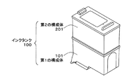
図1は、本発明の一実施形態のインクタンク100を含むインクカートリッジの外観斜視図である。これに対して、図4は、従来のインクタンク400を含むインクカートリッジの外観斜視図である。
FIG. 1 is an external perspective view of an ink cartridge including an
以下、これらを比較しながら説明する。 Hereinafter, it demonstrates, comparing these.
図1に示すように、本実施形態のインクタンク100は、インク供給部104(図2参照)を有する第1の構成体101と、バッファー室204および大気連通口205(図2参照)を有する第2の構成体201と、を連結した構成となっている。
As shown in FIG. 1, the
第1の構成体101は、既存カートリッジを流用したものであり、第1の吸収体102(図2参照)に保持されるインク量が一定の共通ユニットである。また、第2の構成体201は、第2の吸収体202(図2参照)に保持されるインク量がそれぞれ異なる複数のユニットの中から選択されたものである。
The first
このように、本実施形態のインクカートリッジ100は、既存カートリッジを流用した第1の構成体101に対して、必要なインク量の第2の構成体201を1つだけ選択して連結することでインクタンクを構成することができる。そのため、各種インク量のバリエーションにも対応可能で、市場ニーズにも容易かつ迅速に対応することができる。
As described above, the
これに対して、図4に示すように、従来のインクタンク400は、インク量の増量分に合わせて再設計した、一体型の大容量インクタンクとなっている。したがって、インク量を増量する度に、インクタンクに関わる全部品の検討・再設計を行い、試作型を新規製作して試作・評価を行うことになり、多大な費用と時間を要してしまため、市場ニーズへの容易かつ迅速な対応が困難である。 On the other hand, as shown in FIG. 4, the conventional ink tank 400 is an integrated large-capacity ink tank redesigned in accordance with the increase in the ink amount. Therefore, every time the amount of ink is increased, all parts related to the ink tank are examined and redesigned, and a prototype is newly manufactured and prototyped and evaluated. Therefore, it is difficult to easily and quickly respond to market needs.
以下、図2および図3を用いて、本実施形態のインクタンク100の構成について詳細に説明していく。
Hereinafter, the configuration of the
図2は、図1に示したインクカートリッジ100を側面側から見た断面図である。なお、図2には、第1の構成体101に収容される第1の吸収体102および第2の構成体201に収容される第2の吸収体202の吸収体挿入開口からの寸法関係も示してある。
FIG. 2 is a cross-sectional view of the
図3は、図1に示した第1の構成体101および第2の構成体201を、それぞれ上面および下面から見た図である。なお、図3には、第1の吸収体102と第2の吸収体202とが接触する領域も示してある。
FIG. 3 is a view of the
図2に示すように、第1の構成体101は、インクを吸収し保持する第1の吸収体102を収容し、インクタンク100の構成部品となる。また、第1の構成体101は、第1の吸収体102とフィルター103を介して接触し、第1の吸収体102に保持されたインクをインク吐出部材105に供給するインク供給部104を有している。
As shown in FIG. 2, the first
第2の構成体201は、インクを吸収し保持する第2の吸収体202を収容し、インクタンク100の構成部品となる。また、第2の構成体201は、第2の吸収体202から流出したインクを一時的に貯留するバッファー室204と、第2の構成体201の内部と外部の大気とを連通させる大気連通口205と、を有している。
The
第1の構成体101と第2の構成体201とは、第1の吸収体102と第2の吸収体202とが接触するように連結される。
The
ここで、インク供給部104と接触する第1の吸収体102の繊維密度は、インク供給性の観点から、第2の吸収体202の繊維密度よりも大きくすることが好ましい。吸収体の繊維密度が大きいほどインクを保持する毛管力が大きくなることは公知であり、毛管力が大きな部分にインクは集まってくる。
Here, the fiber density of the
第1の吸収体102は、第1の構成体101の吸収体挿入開口(=第2の構成体201との連結面)から外側にははみ出さないように第1の構成体101に挿入されている。また、第2の吸収体202は、第2の構成体201の吸収体挿入開口(=第1の構成体101との連結面)から外側にはみ出すように第2の構成体201に挿入されている。
The first
このように、第1の構成体101は、吸収体挿入開口から第1の吸収体102を内部に押し込むような構成としたため、第2の構成体201との連結時に、第2の吸収体202の挟み込みを防止することができる。
Thus, since the
また、第1の吸収体102と第2の吸収体202とは接触することが重要で、さらにはその接触部分が圧縮された状態にあることがより好ましい。
Further, it is important that the first
そこで、第1の吸収体102の先端から第1の構成体101の吸収体挿入開口までの凹量Aと、第2の吸収体202の先端から第2の構成体201の吸収体挿入開口までの凸量Bとは、「凹量A<凸量B」となるような関係にする。これにより、第1の吸収体102と第2の吸収体202とを確実に圧縮された状態で接触させることができる。なお、この寸法関係は、各部品公差や、第1の吸収体102と第2の吸収体202との圧縮状態をどのレベルにするか等よって決められる。
Therefore, the concave amount A from the tip of the
また、第1の構成体101と第2の構成体201とは溶着等の方法で連結するが、より強度的に信頼性の高いものとするには振動溶着を用いることが好ましい。
Moreover, although the
振動溶着は、周波数が低い分、振幅が大きくなる溶着方法である。周波数が低いことは各部品に与えるダメージを少なくできるというメリットがあるが、その反面、振幅を大きくとるため、連結部品同士の連結方向に対して垂直な方向への移動量が大きくなる。したがって、振動溶着時の第2の吸収体202の挟み込みが懸念される。 Vibration welding is a welding method in which the amplitude is increased as the frequency is lower. The low frequency has the advantage that damage to each component can be reduced, but on the other hand, since the amplitude is increased, the amount of movement of the connected components in the direction perpendicular to the connecting direction increases. Therefore, the second absorber 202 may be caught during vibration welding.
そこで、振動溶着時の第2の吸収体202の挟み込みを確実に防ぐため、第2の吸収体202における第1の吸収体102と対向する面のサイズを、その面が第1の吸収体102における第2の吸収体202と対向する面の内側に収まるようなサイズとしている。そのために、第2の構成体201の内部には吸収体側面リブ203が複数設けてある。
Therefore, in order to reliably prevent the second absorbent body 202 from being caught during vibration welding, the size of the surface of the second absorbent body 202 that faces the first
さらに、振動溶着時の移動方向において、第2の吸収体202における第1の吸収体102と対向する面の淵と、第1の吸収体102における第2の吸収体202と対向する面の淵と、の間の距離を、振動溶着時の移動量よりも大きくしている。
Furthermore, in the moving direction at the time of vibration welding, wrinkles on the surface of the second absorber 202 facing the
第1の吸収体102と第2の吸収体202のサイズの関係は、図3に示している。第1の吸収体102は、第1の構成体101の内側全体に挿入されるのに対し、第2の吸収体202は、第2の構成体201の内側全体に設けられた複数の吸収体側面リブ203の内側に挿入されている。このため、第1の構成体101と第2の構成体201とが連結される場合、第1の吸収体102と第2の吸収体202とが接触する領域は、第2の吸収体202の接触面と同じ面積になる。
The relationship between the sizes of the first
また、振動溶着時には、第1の吸収体102と第2の吸収体202とは既に接触した状態にあるので、接触する領域において抵抗力が発生し、溶着信頼性への影響、または吸収体同士の擦れによるゴミ発生等の懸念が考えられる。
Further, at the time of vibration welding, the
そこで、図2に示すように、第2の吸収体202の先端から吸収体側面リブ203の先端までの凸量Cの領域を、「凸量B<凸量C」となるようにして、第2の吸収体202の自由領域とする。これにより、振動溶着時に第2の吸収体202の変形を可能にし、溶着への影響および吸収体同士の擦れを防ぎ、信頼性を確保することができる。
Therefore, as shown in FIG. 2, the region of the convex amount C from the tip of the second absorber 202 to the tip of the absorber
ここで、本実施形態のインクタンク100の製造方法について説明する。
Here, a manufacturing method of the
まず、第1の吸収体102を、第1の構成体101の吸収体挿入開口から外側にははみ出さないように第1の構成体101に挿入する(第1の挿入工程)。第1の構成体101は、上述のように、第1の吸収体102に保持されるインク量が一定の共通ユニットである。したがって、共通ラインで第1の構成体101を製造することができる。
First, the
次に、第2の吸収体202を、第2の構成体201の吸収体挿入開口から外側にはみ出すように第2の構成体201に挿入する(第2の挿入工程)。第2の構成体201は、上述のように、第2の吸収体202に保持されるインク量がそれぞれ異なる複数のユニットの中から選択されるものである。したがって、第2の吸収体202にて保持するインク量に応じて分けられた複数のオフラインのいずれかで第2の構成体201を製造することができる。
Next, the 2nd absorber 202 is inserted in the
その後、複数のオフラインでそれぞれ製造された第2の構成体201の中から、第2の吸収体202にて保持するインク量に応じて、第2の構成体201を1つだけを選択する。そして、選択された第2の構成体201と共通ラインで製造された第1の構成体101とを、第1の吸収体102と第2の吸収体202とが押圧接触するように連結する(連結工程)。
Thereafter, only one
したがって、インクタンク100の生産ラインにおいて、生産メインラインとなる第1の構成体101のラインは共通化が可能になる。また、複数のオフラインで製造される第2の構成体201から自由に第2の構成体201を選択することが可能になる。これにより、生産メインラインの共通化や工程の簡略化が図れるため、生産ラインの投資抑制が可能となり、製造コストがコストダウンする。その結果、信頼性の高いインクカートリッジをユーザーに安価で提供することができる。
Therefore, in the production line of the
100 インクタンク
101 第1の構成体
102 第1の吸収体
103 フィルター
104 インク供給部
105 インク吐出部材
201 第2の構成体
202 第2の吸収体
203 吸収体側面リブ
204 バッファー室
205 大気連通口
DESCRIPTION OF
Claims (5)
前記第1の吸収体は、前記第1の構成体と前記第2の構成体との連結方向において、前記第1の吸収体が前記第1の構成体の吸収体挿入開口から外側にはみ出さないように挿入され、
前記第2の吸収体は、前記第1の構成体と前記第2の構成体との連結方向において、前記第2の吸収体が前記第2の構成体の吸収体挿入開口から外側にはみ出すように挿入され、
前記第2の吸収体における前記第1の吸収体と対向する面のサイズは、当該面が前記第1の吸収体における前記第2の吸収体と対向する面の内側に収まるようなサイズであり、
前記第1の構成体と前記第2の構成体とは振動溶着により連結され、前記振動溶着時の移動方向において、前記第2の吸収体における前記第1の吸収体と対向する面の淵と、前記第1の吸収体における前記第2の吸収体と対向する面の淵と、の間の距離は、前記振動溶着時の振幅よりも大きいことを特徴とする、インクタンク。 A first and a second structural body for accommodating first and second absorbers for holding ink, respectively, wherein the first absorber and the second absorber are in contact with each other; An ink tank in which a structure and the second structure are connected,
The first absorbent body protrudes outward from the absorbent body insertion opening of the first structural body in the connecting direction of the first structural body and the second structural body. Inserted so that there is no
The second absorbent body protrudes outward from the absorbent body insertion opening of the second structural body in the connecting direction of the first structural body and the second structural body. Inserted into
The size of the surface of the second absorber facing the first absorber is such that the surface fits inside the surface of the first absorber facing the second absorber. ,
The first structural body and the second structural body are coupled by vibration welding, and a ridge on a surface of the second absorbent body facing the first absorbent body in a moving direction at the time of vibration welding. An ink tank characterized in that a distance between a surface of the first absorbent body facing the second absorbent body is larger than an amplitude at the time of vibration welding .
前記第1の吸収体に保持されたインクをインク吐出部材に供給するインク供給部を有し、
前記第2の構成体は、
前記第2の吸収体から流出したインクを一時的に貯留するバッファー室と、
前記第2の構成体の内部と外部の大気とを連通させる大気連通口と、を有し、
前記第1の吸収体は、前記第2の吸収体よりも毛管力が高いことを特徴とする、請求項1に記載のインクタンク。 The first component is:
An ink supply unit that supplies ink held by the first absorber to an ink discharge member;
The second component is:
A buffer chamber for temporarily storing ink flowing out of the second absorber;
An atmosphere communication port for communicating the inside of the second structural body with the outside atmosphere;
The ink tank according to claim 1 , wherein the first absorber has a higher capillary force than the second absorber.
前記第1の構成体と前記第2の構成体との連結方向において、前記第2の吸収体の先端から前記第2の構成体の吸収体挿入開口までの凸量は、前記第1の吸収体の先端から前記第1の構成体の吸収体挿入開口までの凹量よりも大きいことを特徴とする、請求項1もしくは2のいずれか1項に記載のインクタンク。 In the state before the first and second absorbers are inserted into the first and second structural bodies, respectively, and before the first structural body and the second structural body are connected,
In the connecting direction of the first structure and the second structure, the amount of protrusion from the tip of the second absorber to the absorber insertion opening of the second structure is the first absorption. It is larger than凹量from the tip of the body to the absorbent body insertion opening of the first structure, an ink tank according to any one of claims 1 or 2.
前記第2の構成体は、前記第2の吸収体にて保持するインク量がそれぞれ異なる複数のユニットの中から選択されたものであることを特徴とする、請求項1〜4のいずれか1項に記載のインクタンク。 The first component is a common unit in which the amount of ink retained by the first absorber is constant,
Wherein the second structure is characterized in that the amount of ink held in the second absorber is one selected from among a plurality of different units each one of the claims 1-4 1 The ink tank according to the item.
Priority Applications (1)
| Application Number | Priority Date | Filing Date | Title |
|---|---|---|---|
| JP2007295690A JP5014076B2 (en) | 2007-11-14 | 2007-11-14 | Ink tank |
Applications Claiming Priority (1)
| Application Number | Priority Date | Filing Date | Title |
|---|---|---|---|
| JP2007295690A JP5014076B2 (en) | 2007-11-14 | 2007-11-14 | Ink tank |
Publications (2)
| Publication Number | Publication Date |
|---|---|
| JP2009119703A JP2009119703A (en) | 2009-06-04 |
| JP5014076B2 true JP5014076B2 (en) | 2012-08-29 |
Family
ID=40812408
Family Applications (1)
| Application Number | Title | Priority Date | Filing Date |
|---|---|---|---|
| JP2007295690A Expired - Fee Related JP5014076B2 (en) | 2007-11-14 | 2007-11-14 | Ink tank |
Country Status (1)
| Country | Link |
|---|---|
| JP (1) | JP5014076B2 (en) |
Families Citing this family (2)
| Publication number | Priority date | Publication date | Assignee | Title |
|---|---|---|---|---|
| JP5736125B2 (en) * | 2010-05-25 | 2015-06-17 | エステー産業株式会社 | Ink car ridge |
| JP6497152B2 (en) * | 2015-03-19 | 2019-04-10 | セイコーエプソン株式会社 | Tank, tank unit, liquid injection system |
Family Cites Families (2)
| Publication number | Priority date | Publication date | Assignee | Title |
|---|---|---|---|---|
| JP3160509B2 (en) * | 1995-09-29 | 2001-04-25 | キヤノン株式会社 | Ink jet ink cartridge and method of manufacturing the same |
| JP3658373B2 (en) * | 2002-02-22 | 2005-06-08 | キヤノン株式会社 | Liquid storage container, ink jet cartridge, and ink jet recording apparatus |
-
2007
- 2007-11-14 JP JP2007295690A patent/JP5014076B2/en not_active Expired - Fee Related
Also Published As
| Publication number | Publication date |
|---|---|
| JP2009119703A (en) | 2009-06-04 |
Similar Documents
| Publication | Publication Date | Title |
|---|---|---|
| JP5569475B2 (en) | Liquid container and liquid ejecting apparatus | |
| JP3667296B2 (en) | Ink tank | |
| JP3667295B2 (en) | Ink tank | |
| US20050264624A1 (en) | Liquid contianer and inkjet cartridge | |
| JP2008074090A (en) | Ink tank | |
| US20040246317A1 (en) | Liquid container, liquid container holder and recording head cartridge | |
| JP6230231B2 (en) | Ink tank | |
| JP5014076B2 (en) | Ink tank | |
| JP2684508B2 (en) | Inkjet cartridge and inkjet printer | |
| JP2009262525A (en) | Ink tank and inkjet recording device | |
| JPH058405A (en) | Ink feeder equipped with a plurality of liquid absorbing components and ink jet recording head equipped therewith | |
| JP2012206383A (en) | Ball-point pen | |
| JP2009090542A (en) | Inkjet recording cartridge | |
| JP4946204B2 (en) | Ink cartridge and printer | |
| JPH0820115A (en) | Ink tank, ink jet head and ink jet device employing said tank | |
| JP2004230806A (en) | Inkjet recorder | |
| CN217145381U (en) | Regeneration ink box | |
| JP3258311B2 (en) | Ink tank and ink jet device | |
| CN219927289U (en) | Ink box | |
| JPH08183184A (en) | Ink tank, ink jet cartridge and ink jet recording device | |
| JP2006116861A (en) | Ink cartridge | |
| JPH09216382A (en) | Ink jet recording-liquid container, ink jet cartridge and printer | |
| JPH09216377A (en) | Manufacture of recording-liquid tank, recording-liquid tank, method for ink injection, and manufacture of ink-jet cartridge | |
| JPH0768770A (en) | Ink tank for ink jetting and ink jet recorder using the ink tank | |
| JP2852914B2 (en) | Recording liquid container for inkjet |
Legal Events
| Date | Code | Title | Description |
|---|---|---|---|
| A621 | Written request for application examination |
Free format text: JAPANESE INTERMEDIATE CODE: A621 Effective date: 20100607 |
|
| A977 | Report on retrieval |
Free format text: JAPANESE INTERMEDIATE CODE: A971007 Effective date: 20120209 |
|
| A131 | Notification of reasons for refusal |
Free format text: JAPANESE INTERMEDIATE CODE: A131 Effective date: 20120214 |
|
| A521 | Written amendment |
Free format text: JAPANESE INTERMEDIATE CODE: A523 Effective date: 20120411 |
|
| TRDD | Decision of grant or rejection written | ||
| A01 | Written decision to grant a patent or to grant a registration (utility model) |
Free format text: JAPANESE INTERMEDIATE CODE: A01 Effective date: 20120508 |
|
| A01 | Written decision to grant a patent or to grant a registration (utility model) |
Free format text: JAPANESE INTERMEDIATE CODE: A01 |
|
| A61 | First payment of annual fees (during grant procedure) |
Free format text: JAPANESE INTERMEDIATE CODE: A61 Effective date: 20120605 |
|
| FPAY | Renewal fee payment (event date is renewal date of database) |
Free format text: PAYMENT UNTIL: 20150615 Year of fee payment: 3 |
|
| R151 | Written notification of patent or utility model registration |
Ref document number: 5014076 Country of ref document: JP Free format text: JAPANESE INTERMEDIATE CODE: R151 |
|
| FPAY | Renewal fee payment (event date is renewal date of database) |
Free format text: PAYMENT UNTIL: 20150615 Year of fee payment: 3 |
|
| LAPS | Cancellation because of no payment of annual fees |