JP5007228B2 - Image cleanup and precoding - Google Patents
Image cleanup and precoding Download PDFInfo
- Publication number
- JP5007228B2 JP5007228B2 JP2007527809A JP2007527809A JP5007228B2 JP 5007228 B2 JP5007228 B2 JP 5007228B2 JP 2007527809 A JP2007527809 A JP 2007527809A JP 2007527809 A JP2007527809 A JP 2007527809A JP 5007228 B2 JP5007228 B2 JP 5007228B2
- Authority
- JP
- Japan
- Prior art keywords
- pixel
- pixels
- filter kernel
- digital image
- image
- Prior art date
- Legal status (The legal status is an assumption and is not a legal conclusion. Google has not performed a legal analysis and makes no representation as to the accuracy of the status listed.)
- Expired - Fee Related
Links
- 238000000034 method Methods 0.000 claims abstract description 82
- 238000001914 filtration Methods 0.000 claims abstract description 58
- 230000001419 dependent effect Effects 0.000 claims abstract description 31
- 238000010606 normalization Methods 0.000 claims abstract description 5
- 230000006870 function Effects 0.000 claims description 51
- 238000009792 diffusion process Methods 0.000 claims description 30
- 230000015654 memory Effects 0.000 claims description 23
- 238000009499 grossing Methods 0.000 claims description 19
- 230000006835 compression Effects 0.000 claims description 14
- 238000007906 compression Methods 0.000 claims description 14
- 230000009466 transformation Effects 0.000 claims description 6
- 238000004590 computer program Methods 0.000 claims 2
- 230000003252 repetitive effect Effects 0.000 claims 1
- 238000010586 diagram Methods 0.000 description 37
- 230000008569 process Effects 0.000 description 37
- 238000012545 processing Methods 0.000 description 28
- 238000006243 chemical reaction Methods 0.000 description 13
- 238000004891 communication Methods 0.000 description 11
- 239000013598 vector Substances 0.000 description 10
- 238000013459 approach Methods 0.000 description 8
- 239000011159 matrix material Substances 0.000 description 8
- 238000010276 construction Methods 0.000 description 6
- 238000003706 image smoothing Methods 0.000 description 6
- 238000003707 image sharpening Methods 0.000 description 5
- 230000007704 transition Effects 0.000 description 5
- 238000004800 variational method Methods 0.000 description 5
- 238000007619 statistical method Methods 0.000 description 4
- 238000004422 calculation algorithm Methods 0.000 description 3
- 230000008859 change Effects 0.000 description 3
- 230000004069 differentiation Effects 0.000 description 3
- 238000013507 mapping Methods 0.000 description 3
- 230000009467 reduction Effects 0.000 description 3
- 238000000844 transformation Methods 0.000 description 3
- 238000004364 calculation method Methods 0.000 description 2
- 230000008878 coupling Effects 0.000 description 2
- 238000010168 coupling process Methods 0.000 description 2
- 238000005859 coupling reaction Methods 0.000 description 2
- 230000006872 improvement Effects 0.000 description 2
- 238000012804 iterative process Methods 0.000 description 2
- 238000012986 modification Methods 0.000 description 2
- 230000004048 modification Effects 0.000 description 2
- 230000003287 optical effect Effects 0.000 description 2
- 238000003672 processing method Methods 0.000 description 2
- 238000013139 quantization Methods 0.000 description 2
- 238000005096 rolling process Methods 0.000 description 2
- 238000002945 steepest descent method Methods 0.000 description 2
- 238000012546 transfer Methods 0.000 description 2
- 238000005452 bending Methods 0.000 description 1
- 230000003247 decreasing effect Effects 0.000 description 1
- 230000000694 effects Effects 0.000 description 1
- 230000002708 enhancing effect Effects 0.000 description 1
- 239000000203 mixture Substances 0.000 description 1
- 238000012805 post-processing Methods 0.000 description 1
- 238000011045 prefiltration Methods 0.000 description 1
- 230000004044 response Effects 0.000 description 1
Images


Classifications
-
- G—PHYSICS
- G06—COMPUTING; CALCULATING OR COUNTING
- G06T—IMAGE DATA PROCESSING OR GENERATION, IN GENERAL
- G06T5/00—Image enhancement or restoration
- G06T5/70—Denoising; Smoothing
-
- G—PHYSICS
- G06—COMPUTING; CALCULATING OR COUNTING
- G06T—IMAGE DATA PROCESSING OR GENERATION, IN GENERAL
- G06T5/00—Image enhancement or restoration
- G06T5/20—Image enhancement or restoration using local operators
-
- G—PHYSICS
- G06—COMPUTING; CALCULATING OR COUNTING
- G06T—IMAGE DATA PROCESSING OR GENERATION, IN GENERAL
- G06T2207/00—Indexing scheme for image analysis or image enhancement
- G06T2207/10—Image acquisition modality
- G06T2207/10016—Video; Image sequence
-
- G—PHYSICS
- G06—COMPUTING; CALCULATING OR COUNTING
- G06T—IMAGE DATA PROCESSING OR GENERATION, IN GENERAL
- G06T2207/00—Indexing scheme for image analysis or image enhancement
- G06T2207/10—Image acquisition modality
- G06T2207/10024—Color image
-
- G—PHYSICS
- G06—COMPUTING; CALCULATING OR COUNTING
- G06T—IMAGE DATA PROCESSING OR GENERATION, IN GENERAL
- G06T2207/00—Indexing scheme for image analysis or image enhancement
- G06T2207/20—Special algorithmic details
- G06T2207/20172—Image enhancement details
- G06T2207/20192—Edge enhancement; Edge preservation
Landscapes
- Physics & Mathematics (AREA)
- General Physics & Mathematics (AREA)
- Engineering & Computer Science (AREA)
- Theoretical Computer Science (AREA)
- Image Processing (AREA)
- Facsimile Image Signal Circuits (AREA)
- Picture Signal Circuits (AREA)
Abstract
Description
本出願は、参照により本明細書に組み込まれる、2004年6月14日に出願した「Methods and Systems for Image Clean−Up and Pre−coding」という表題の米国仮出願第60/579,840号の優先権を主張するものである。 This application is incorporated by reference in US Provisional Application No. 60 / 579,840 entitled “Methods and Systems for Image for Image Clean-Up and Pre-coding” filed on June 14, 2004, which is incorporated herein by reference. It claims priority.
本発明は、一般的に、画像処理に関する関するものであり、より具体的には、画像および映像のクリーンアップおよび前置符号化(pre-coding)に関するものである。 The present invention relates generally to image processing, and more specifically to image and video cleanup and pre-coding.
従来の画像ノイズ除去(または低減)アルゴリズムは、統計的方法およびカーネル法の2つに分類することができる。統計的方法のアルゴリズムの1つに、中央値フィルタリングがある。中央値フィルタリングでは、画像内のクリーンアップすべき(ノイズを含む)ピクセルの集合内のそれぞれのピクセルに対する値は、それぞれのピクセルを中心とする指定されたウィンドウ内の中央ピクセル値として決定される。中央値フィルタリングは、インパルスノイズの除去または低減に有効な場合があるが、ガウス(白色)ノイズを除去するのは困難であることが多く、ぼけた画像にすることがある(つまり、画像は平滑化される)。ぼけは、ウィンドウが大きいとき、例えばインパルスノイズの割合が高い画像内で、比較的顕著である。 Conventional image denoising (or reduction) algorithms can be classified into two methods: statistical methods and kernel methods. One statistical method algorithm is median filtering. In median filtering, the value for each pixel in the set of pixels to be cleaned up (including noise) in the image is determined as the median pixel value in a specified window centered on each pixel. Median filtering can be effective in removing or reducing impulse noise, but Gaussian (white) noise is often difficult to remove and can result in a blurred image (that is, the image is smooth) ). The blur is relatively noticeable when the window is large, for example, in an image with a high proportion of impulse noise.
他の統計的方法である、順序統計量(order-statistics)(OS)フィルタリングを使用すると、ぼけの量や程度を低減することができる。OSフィルタリングでは、ウィンドウ内のピクセルの集合は、順序付きシーケンスとして配列され、それぞれのピクセルは、好適な所定の重みを使用してこのシーケンスの一次結合により置き換えられる。しかしならが、同じウィンドウ(形状およびサイズ)および同じ重みを画像内のそれぞれのピクセルに対し使用することができる。したがって、画像全体の鮮鋭さを保存または維持することは困難なことが多い。 Another statistical method, order-statistics (OS) filtering, can be used to reduce the amount and degree of blur. In OS filtering, the set of pixels in the window is arranged as an ordered sequence, and each pixel is replaced by a linear combination of this sequence using a suitable predetermined weight. However, the same window (shape and size) and the same weight can be used for each pixel in the image. Therefore, it is often difficult to preserve or maintain the sharpness of the entire image.
移動平均(MA)フィルタリング、無限インパルス応答(IIR)、または自己回帰移動平均(ARMA)フィルタリング(つまり、MAを自己回帰帰還と併せた)、および畳み込みフィルタリングなどのカーネル法は、ガウスノイズを低減するのにより有効であるが、インパルスノイズを低減するのにはあまり有効でない場合がある。それに加えて、フィルタ係数(フィルタ重みとも呼ばれる)に応じて、カーネル法は、画像の鮮鋭さを保存する際に統計的方法に比べてなおそいっそう困難な場合がある。 Kernel methods such as moving average (MA) filtering, infinite impulse response (IIR), or autoregressive moving average (ARMA) filtering (ie, MA combined with autoregressive feedback), and convolution filtering reduce Gaussian noise However, it may not be very effective in reducing impulse noise. In addition, depending on the filter coefficients (also called filter weights), the kernel method may be even more difficult than the statistical method in preserving image sharpness.
統計的方法およびカーネル法を含む、従来の画像フィルタリングは、画像平滑化により、したがって画像の鮮鋭さを犠牲にして、ノイズ低減を行うことが多い。これにより、画像の過剰なぼけが生じうる。これらの方法を修正して、ある程度の画像鮮鋭さを保存することが試みられているが(例えば、逆グラディエントに従ってそれぞれのピクセルの畳み込みマスクを使用することにより)、このようなアプローチは、計算コストおよび複雑度の増大を伴い、また画像の多段処理(つまり、画像処理の何回もの反復)を使用することが多い。 Conventional image filtering, including statistical and kernel methods, often provides noise reduction by image smoothing and thus at the expense of image sharpness. This can cause excessive blurring of the image. While attempts have been made to modify these methods to preserve some image sharpness (eg, by using a convolution mask for each pixel according to an inverse gradient), such an approach is computationally expensive. And with increased complexity, and often uses multi-stage processing of images (ie, multiple iterations of image processing).
画像ノイズ除去技術の最近の進歩として、「最大事後確率」(MAP)および変分法がある。MAPアプローチは、本質的に統計的(つまり、離散的)である。変分法は、解析的であり、多くの場合、曲げまたは内部(「先験的」)エネルギー汎関数の総和として定義される、エネルギー汎関数の最小化問題として提示される。内部エネルギー汎関数は、出力画像の画質を決定するものであり、外部エネルギー汎関数は、クリーンアップすべき入力画像との近似を測定するものである。ノイズが含まれる入力画像(外部エネルギーにより支配される)と比較して出力「クリーン」画像の画質(平滑度/鮮鋭度)および忠実度(fidelity)のバランスをとるためのパラメータとして正定数が使用される。エネルギー最小化問題のオイラーラグランジュ方程式を解く最急降下法から、(等方性および異方性)拡散および拡散反応偏微分方程式(PDE)が得られる。変分法および他の最近の関係するアプローチ(異方性拡散または拡散反応PDEの数値解など)は、通常、上述の従来のアルゴリズムに勝る改善をもたらすが、この改善は、計算コストおよび複雑さの増大を伴い、また画像の多段処理を使用することも多い。 Recent advances in image denoising techniques include “maximum posterior probability” (MAP) and variational methods. The MAP approach is inherently statistical (ie, discrete). Variational methods are analytical and are often presented as energy functional minimization problems, defined as the sum of bending or internal ("a priori") energy functionals. The internal energy functional determines the image quality of the output image, and the external energy functional measures the approximation with the input image to be cleaned up. A positive constant is used as a parameter to balance the quality (smoothness / sharpness) and fidelity of the output “clean” image compared to the noisy input image (dominated by external energy) Is done. From the steepest descent method to solve the Euler-Lagrange equation for the energy minimization problem, the (isotropic and anisotropic) diffusion and diffusion reaction partial differential equations (PDEs) are obtained. Variational methods and other recent related approaches (such as the numerical solution of anisotropic diffusion or diffusion reaction PDE) usually provide improvements over the conventional algorithms described above, but this improvement is computational cost and complexity In many cases, multistage processing of images is used.
したがって、画像内容(画像テクスチャおよび画像エッジなど)を実質的に保持しつつ画像中のノイズを除去または低減する改善された画像処理方法が必要である。また、計算コストの低減、複雑さの低減、および画像処理における1パス化または処理段数の低減が必要である。 Accordingly, there is a need for an improved image processing method that removes or reduces noise in an image while substantially retaining image content (such as image texture and image edges). Further, it is necessary to reduce the calculation cost, the complexity, and the one-pass or the number of processing stages in the image processing.
デジタル画像をフィルタ処理する方法について説明する。第1のフィルタリングパラメータに従って、デジタル画像内のノイズを平滑化し、デジタル画像内の画像エッジに関連する空間周波数を保存するために、ピクセルの集合内のそれぞれのピクセルに対しフィルタカーネルが適用される。フィルタカーネルは、それぞれのピクセルの関数であり、それぞれのピクセルに対する閉形式(closed form)を持つ。フィルタカーネルは、隣接ピクセルの第1の集合から寄与因子(contributions)を含み、フィルタカーネル内の要素の和が実質的固定値に等しくなるように内容依存の正規化(contend-dependent normalization)が行われる。言い換えると、要素の和は、固定された1つの値に等しいか、ほぼ等しい、ということである。 A method for filtering a digital image will be described. A filter kernel is applied to each pixel in the set of pixels to smooth noise in the digital image and preserve the spatial frequency associated with image edges in the digital image according to the first filtering parameter. The filter kernel is a function of each pixel and has a closed form for each pixel. The filter kernel includes contributions from the first set of neighboring pixels and performs content-dependent normalization so that the sum of the elements in the filter kernel is equal to a substantially fixed value. Is called. In other words, the sum of the elements is equal to or approximately equal to one fixed value.
適用は、それぞれのピクセルに対する単一パスを含むことができる。適用は、フィルタ処理されたデジタル画像が出力するために、ピクセルの集合内のピクセル毎に実行することができる。フィルタカーネルをピクセルの集合内のそれぞれのピクセルにさらに1回または複数回適用することで、フィルタ処理されたデジタル画像に実質的な変化が生じないようにすることができる。 The application can include a single pass for each pixel. Application can be performed for each pixel in the set of pixels in order to output a filtered digital image. The filter kernel can be applied one or more times to each pixel in the set of pixels so that no substantial change occurs in the filtered digital image.
第1のフィルタリングパラメータは、平滑化と鮮鋭化との境界を決定することができる。第1のフィルタリングパラメータは、閾値を超える空間周波数を含むデジタル画像内の1つの位置におけるノイズの平滑化を減らすことによりデジタル画像内のテクスチャ情報を実質的に維持することができる。 The first filtering parameter can determine the boundary between smoothing and sharpening. The first filtering parameter can substantially maintain texture information in the digital image by reducing noise smoothing at one location in the digital image that includes a spatial frequency that exceeds a threshold.
フィルタカーネル内の非中心要素は、隣接ピクセルの第1の集合内のピクセルと異方性拡散方程式の離散化(the discretization of the anisotropic diffusion equation)におけるそれぞれのピクセルとの間の差の大きさを含むことができる。フィルタカーネル内の中心ピクセルは、それぞれのピクセルに対応しうる。第1のフィルタリングパラメータは、異方性拡散方程式の離散化における時間ステップを内容依存のスケール(content-dependent scale)にマッピングすることができる。異方性拡散方程式の離散化における伝導性(conductivity)は、ウェーブレット変換の関数であってよい。伝導関数からの離散伝導要素はルックアップテーブルとして実装することができる。 A non-central element in the filter kernel determines the magnitude of the difference between a pixel in the first set of neighboring pixels and each pixel in the discretization of the anisotropic diffusion equation. Can be included. A central pixel in the filter kernel may correspond to each pixel. The first filtering parameter can map a time step in discretization of the anisotropic diffusion equation to a content-dependent scale. Conductivity in discretization of the anisotropic diffusion equation may be a function of the wavelet transform. Discrete conduction elements from the transfer function can be implemented as look-up tables.
フィルタカーネルは、サイズ(2m+1)×(2n+1)のウィンドウに対応し、隣接ピクセルの第1の集合を含むことができる。フィルタカーネルに対するmおよびnは、ピクセルサイズの関数とすることができる。mは、nに等しくてもよい。 The filter kernel can correspond to a window of size (2m + 1) × (2n + 1) and can include a first set of neighboring pixels. M and n for the filter kernel can be a function of pixel size. m may be equal to n.
いくつかの実施形態では、この方法は、さらに、フィルタカーネルを使用してピクセルの色または色成分を修正することを含むことができる。 In some embodiments, the method can further include modifying the color or color component of the pixel using a filter kernel.
いくつかの実施形態では、フィルタカーネルは、隣接ピクセルの第2の集合からの寄与因子を含み、さらに第2のフィルタリングパラメータに従う。 In some embodiments, the filter kernel includes a contributing factor from a second set of neighboring pixels and further obeys a second filtering parameter.
デジタル画像をフィルタ処理する方法の他の実施形態では、フィルタリングパラメータに従って、デジタル画像内のノイズを平滑化し、デジタル画像内の画像エッジに関連する空間周波数を保存するために、ピクセルの集合内のそれぞれのピクセルに対しフィルタカーネルが適用される。フィルタ処理されたピクセルは In another embodiment of the method for filtering a digital image, each of the sets of pixels in the set of pixels is adapted to smooth noise in the digital image and preserve spatial frequencies associated with image edges in the digital image according to filtering parameters. The filter kernel is applied to the pixels. The filtered pixels

![]()
![]()
デジタル画像をフィルタ処理する方法およびフィルタ処理するための関係する装置では、ノイズを低減するととともに、画像内容を実質的に保存する。また、この方法および関係する装置は、計算コストの低減、複雑さの低減、およびデジタル画像の処理における1パス化または処理段数の低減も行う。 Methods for filtering digital images and related apparatus for filtering reduce noise and substantially preserve image content. The method and related apparatus also reduce computational costs, reduce complexity, and reduce the number of processing steps to one pass or digital image processing.
本発明をよりよく理解できるように、付属の図面とともに以下の詳細な説明が参照される。 For a better understanding of the present invention, reference is made to the following detailed description taken in conjunction with the accompanying drawings.
図面全体を通して類似の参照番号は、対応する部分を指す。 Like reference numerals refer to corresponding parts throughout the drawings.
そこで、実施形態を詳しく参照するが、その実施例は、付属の図面に例示されている。以下の詳細な説明では、本発明を完全に理解できるように、多数の具体的詳細を述べている。しかし、当業者には、本発明は、これらの具体的詳細がなくても実施されうることは明白であろう。他の例では、これらの実施形態の態様を不必要にわかりにくくしないために、よく知られている方法、手順、コンポーネント、および回路について詳述していない。 Reference will now be made in detail to the embodiments, examples of which are illustrated in the accompanying drawings. In the following detailed description, numerous specific details are set forth in order to provide a thorough understanding of the present invention. However, it will be apparent to those skilled in the art that the present invention may be practiced without these specific details. In other instances, well-known methods, procedures, components, and circuits have not been described in detail so as not to unnecessarily obscure aspects of these embodiments.
画像処理方法ならびに関係する装置およびシステムについて説明する。画像処理は、画像内容を保存し、および/または高めつつ、画質を改善し(例えば、ノイズを低減または除去し)、通信帯域幅を低減し、および/またはデジタル画像またはデジタル画像の集合(映像など)の格納サイズを低減することができる、計算効率の高いフィルタカーネルを中心とする。フィルタカーネルは、JPEG、JPEG−2000、MPEG、H263、またはH264などの画像または映像圧縮法を使用する、画像または映像圧縮システム内に前置フィルタまたは前置符号器として含むことができる。映像圧縮アプリケーションでは、フィルタカーネルは、Iフレーム、Pフレーム、Bフレーム、および/またはマクロブロックの前置フィルタ処理のために、さらにはいわゆる動き補償画像立方体(motion compensated image cubes)の三次元前置フィルタ処理において、使用することができる。フィルタカーネルは、スキャナ、プリンタ、デジタルカメラ(携帯電話、他の携帯デバイス、および/またはスタンドアロンのカメラで使用される)、およびビデオカメラ、さらに画像の後処理で使用することができる。フィルタカーネルは、特定用途向け集積回路(ASIC)、フィールドプログラマブルゲートアレイ(FPGA)、デジタルシグナルプロセッサ(DSP)、または他の集積回路などの、ソフトウェアおよび/またはハードウェアで実装することができる。いくつかの実施形態では、フィルタカーネルは、閉形式を有することができる。フィルタカーネルは、1パスで、それぞれの画像に対応するピクセルの集合に適用され、フィルタ処理された画像を生成することができる。続いてフィルタカーネルをフィルタ処理済み画像に適用することで、フィルタ処理済み画像を実質的に変更のないままにすることができる。例えば、1つまたは複数の空間周波数における大きさの変化は、前置フィルタ処理値の5から10%未満とすることができる。フィルタカーネルが複数回適用された場合、フィルタカーネルに関連する1つまたは複数の平滑化/鮮鋭度パラメータは、変更されなくてもよいし、または修正されてもよい。 An image processing method and related apparatuses and systems will be described. Image processing improves image quality (eg, reduces or eliminates noise), reduces communication bandwidth, and / or digital images or collections of digital images (video) while preserving and / or enhancing image content. And so on), which is capable of reducing the storage size. The filter kernel can be included as a prefilter or precoder in an image or video compression system that uses image or video compression methods such as JPEG, JPEG-2000, MPEG, H263, or H264. In video compression applications, the filter kernel is used for pre-filtering I-frames, P-frames, B-frames, and / or macroblocks, and even three-dimensional prefixes of so-called motion compensated image cubes. It can be used in filtering. The filter kernel can be used in scanners, printers, digital cameras (used in cell phones, other portable devices, and / or stand-alone cameras) and video cameras, as well as image post-processing. The filter kernel may be implemented in software and / or hardware, such as an application specific integrated circuit (ASIC), field programmable gate array (FPGA), digital signal processor (DSP), or other integrated circuit. In some embodiments, the filter kernel can have a closed form. The filter kernel can be applied to the set of pixels corresponding to each image in one pass to generate a filtered image. Subsequent application of the filter kernel to the filtered image can leave the filtered image substantially unchanged. For example, the magnitude change at one or more spatial frequencies can be less than 5 to 10% of the prefiltered value. If the filter kernel is applied multiple times, one or more smoothing / sharpness parameters associated with the filter kernel may not be changed or may be modified.
フィルタカーネルは、非線形であり、内容依存である(そのため、内容依存フィルタまたはCDFとも呼ばれる)。画像内のピクセルのそれぞれの集合について、二次元CDFは、サイズ(2m+1)×(2n+1)(任意の正整数mおよびnについて)のウィンドウまたはフィルタに対応する。CDFは、異方性拡散モデルおよび/または異方性拡散反応モデル(anisotropic diffusion-reaction model)に基づく。異方性拡散モデル内の伝導性の項のグラディエント演算は、水平および/または垂直方向のウェーブレット変換により置き換えることができる。多数の反復ステップを必要とする、結果として得られた偏微分方程式(PDE)の数値解を計算するのではなくて、1つまたは複数の時間−スケール変換が導入される。これらの変換は、PDEの離散化における定数時間ステップパラメータを、一般に画像または画像の部分集合内のそれぞれのピクセルごとに変わる1つまたは複数の内容依存スケールにマッピングする。このマッピングは、ウィンドウ内の中心ピクセルとウィンドウ内の隣接ピクセルの1つまたは複数の集合内のそれぞれのピクセルとの間の差に基づき、および/またはウェーブレット変換によるものである。したがって、一般に、結果として得られるCDFは、処理すべきそれぞれのピクセルついて異なる、つまり、フィルタ係数またはフィルタ重みは、ピクセル値(またはより一般的に、局所的画像内容)が異なれば異なる。しかし、CDFは、閉形式を持ちうる。そのようなものとして、それぞれのピクセルの画像処理は、単一演算で実行することができる、つまり、CDFは、1パスフィルタとすることができる。いくつかの実施形態では、CDFは、複数のパスで実装することができるが、(最大100個の演算または段を使用する)従来の画像フィルタよりも少ない演算または段で済む。 The filter kernel is non-linear and content dependent (hence, also called a content dependent filter or CDF). For each set of pixels in the image, the two-dimensional CDF corresponds to a window or filter of size (2m + 1) × (2n + 1) (for any positive integer m and n). CDF is based on an anisotropic diffusion model and / or an anisotropic diffusion-reaction model. The gradient operation of the conductive term in the anisotropic diffusion model can be replaced by a horizontal and / or vertical wavelet transform. Rather than computing the numerical solution of the resulting partial differential equation (PDE), which requires a large number of iteration steps, one or more time-scale transformations are introduced. These transformations map the constant time step parameters in the PDE discretization to one or more content-dependent scales that typically vary for each pixel in the image or image subset. This mapping is based on the difference between the central pixel in the window and each pixel in one or more sets of neighboring pixels in the window and / or by wavelet transform. Thus, in general, the resulting CDF will be different for each pixel to be processed, ie, the filter coefficients or filter weights will be different for different pixel values (or more generally local image content). However, the CDF can have a closed form. As such, the image processing of each pixel can be performed in a single operation, i.e., the CDF can be a one-pass filter. In some embodiments, the CDF can be implemented with multiple passes, but requires fewer operations or stages than conventional image filters (using up to 100 operations or stages).
CDFの構築時における時間−スケール変換(時間−スケールマッピングとも呼ばれる)は、CDFの所望のウィンドウサイズに応じて、異なる形態をとりうる。ウィンドウサイズは、画像内のピクセルサイズおよび/または画像解像度に従う。例えば、ピクセルサイズが小さい場合(高解像度)、画像内のノイズは、複数ピクセルに及ぶ可能性がある。結果として、このような状況では、大きなウィンドウを使用することができる。複数のフィルタウィンドウサイズ(3×3ウィンドウを含む)に対する微分に関する以下の説明は、任意のウィンドウサイズまで広げることができ、さらに、三次元画像内の画像ノイズを除去または低減する三次元ウィンドウのフィルタまで広げることもできる。そのようなものとして、微分は、一般的アプローチを示すと考えられる。時間−スケール変換は、画像の平滑化/鮮鋭度を調整するために使用することができる少なくとも1つのパラメータを含むことができる。少なくとも1つのパラメータは、事前に定義するか、または自動的におよび/または手作業で調整することができる。調整は、照度、シャッター速度、および/または画像内の画像内容に従う。少なくとも1つのパラメータは、閾値を超える空間周波数を含む画像内の1つの位置におけるノイズの平滑化を減らすことにより、画像内のテクスチャ情報を維持することができる。 Time-scale conversion (also called time-scale mapping) during CDF construction can take different forms depending on the desired window size of the CDF. The window size depends on the pixel size and / or image resolution in the image. For example, if the pixel size is small (high resolution), the noise in the image can span multiple pixels. As a result, large windows can be used in such situations. The following description of differentiation for multiple filter window sizes (including 3 × 3 windows) can be extended to any window size, and further a 3D window filter that removes or reduces image noise in 3D images It can also be expanded. As such, differentiation is considered to represent a general approach. The time-scale transform can include at least one parameter that can be used to adjust the smoothing / sharpness of the image. The at least one parameter can be predefined or adjusted automatically and / or manually. The adjustment depends on the illuminance, shutter speed, and / or image content in the image. At least one parameter can maintain texture information in the image by reducing noise smoothing at one location in the image that includes a spatial frequency that exceeds a threshold.
次に、デジタル画像をフィルタ処理するプロセスならびに関係する装置およびシステムのいくつかの実施形態に注目する。図1は、デジタル画像をフィルタ処理するプロセスの一実施形態100を例示する流れ図である。隣接ピクセルの第1の集合を含むフィルタカーネルのウィンドウサイズが、フィルタリングプロセスのために決定される(112)。CDF用のフィルタカーネルなどのフィルタカーネルが、隣接ピクセルの第1の集合内のそれぞれのピクセルについて決定または構築される(110)。フィルタカーネルは、1のフィルタリングパラメータに応じて、ノイズを平滑化し、画像エッジに関連する空間周波数を保存する。フィルタカーネルに関連する伝導性は、オプションのウェーブレット変換を使用して決定される(114)。隣接するピクセルの第2の集合からのフィルタカーネルへの寄与因子は、第2のフィルタリングパラメータに従って適宜決定されることができる(116)。フィルタカーネルは、隣接ピクセルの第1の集合内のそれぞれのピクセル(中心ピクセルを含む)に適用され、フィルタ処理済みデジタルピクセルを生成する(118)。それぞれのピクセルの色は、対応するフィルタカーネルを使用して適宜修正される(120)。このプロセスは、ピクセルの集合内の追加のピクセルについて、1回または複数回反復することができる(122)。このプロセスは、1つまたは複数の色チャネルについて1回または複数回反復することができる。それぞれの色チャネルは、RGB、YCbCr、YUV、またはYIQ色チャネルとすることができる。プロセス100は、画像内のピクセルの少なくとも1つの部分集合について少なくとも1回の反復を含む複数回の反復を行うことができる。いくつかの実施形態では、並列プロセッサまたは回路を使用して、複数のピクセルを並列に処理することができる。プロセス100は、それよりも少ない演算または追加の演算を含むことができる。更に、2つまたはそれ以上の演算を組み合わせること、および/または演算の順序を変更することができる。
Attention is now directed to some embodiments of the process of filtering digital images and related apparatus and systems. FIG. 1 is a flow diagram illustrating one
図2は、デジタル画像をフィルタ処理するプロセス200の一実施形態を例示する流れ図である。クライアントデバイス210(例えば、イメージセンサを含むデバイス)は、ピクセルの集合をサーバデバイス(例えば、プロセッサ、DSP、またはASICを含むデバイス)212に送信する(214)。該ピクセルの集合が受信される(216)。オプションとして、1つまたは複数のフィルタカーネルが、ピクセルの集合内のそれぞれのピクセルについて決定または構築される(218)。それぞれのフィルタカーネルが、ピクセルの集合内のそれぞれのピクセルに適用され、フィルタ処理済みデジタル画像が生成される(220)。フィルタ処理済みデジタル画像は、クライアントデバイス210に送信される(222)。該フィルタ処理済みデジタル画像が受信される(224)。プロセス200は、それよりも少ない演算または追加の演算を含むことができる。更に、2つまたはそれ以上の演算を組み合わせること、および/または演算の順序を変更することができる。
FIG. 2 is a flow diagram illustrating one embodiment of a
図3は、クライアントコンピュータ、クライアントデバイス、またはサーバデバイス(例えば、プロセッサ、DSP、またはASICを含むデバイス)300の一実施形態を例示するブロック図である。クライアントコンピュータ、クライアントデバイス、またはサーバデバイス300は、少なくとも1つのデータプロセッサ、ビデオプロセッサ、および/または中央演算処理装置(CPU)310、1つまたは複数のオプションのユーザインターフェース314、他のコンピュータ、サーバおよび/またはデバイス400(図4)と通信するための通信またはネットワークインターフェース322、メモリ324、およびこれらのコンポーネントを互いに結合するための1つまたは複数の通信バスまたは信号線312を備えることができる。少なくとも1つのデータプロセッサ、ビデオプロセッサ、および/または中央演算処理装置(CPU)310は、マルチスレッドおよび/または並列処理をサポートすることができる。ユーザインターフェース314は、1つまたは複数のディスプレイ316、キーボード318、および/またはポインタ320(マウスなど)を備えることができる。クライアントまたはサーバデバイス300は、ピクセルの集合の少なくとも部分集合に対しローリングキャッシュとして使用することができる1つまたは複数のキャッシュメモリ308を備えることができる。
FIG. 3 is a block diagram illustrating one embodiment of a client computer, client device, or server device (eg, a device including a processor, DSP, or ASIC) 300. A client computer, client device, or
メモリ324は、ROM、RAM、EPROM、EEPROM、1つまたは複数のフラッシュディスクドライブ、1つまたは複数の光ディスクドライブ、および/または1つまたは複数の磁気ディスク記憶デバイスを含む、高速ランダムアクセスメモリおよび/または不揮発性メモリを含むことができる。メモリ324は、基本システムサービスを処理しハードウェア依存のタスクを実行するためのプロシージャ(つまり、命令セット)を含む、LINUX、UNIX、OS9、またはWINDOWSなどの、オペレーティングシステム326を格納することができる。メモリ324は、さらに、ネットワーク通信モジュール328内に通信プロシージャ(または命令セット)を格納することもできる。通信プロシージャは、1つまたは複数のコンピュータ、サーバ、および/またはデバイス400と通信するために使用される(図4)。
メモリ324は、さらに、画像処理モジュール330(または命令セット)、ウェーブレット変換モジュール336(または命令セット)、色変換モジュール338(または命令セット)、JPEGまたはMPEGなどの符号化/復号化モジュール340(または命令セット)、ピクセルの1つまたは複数の集合342、および/または1つまたは複数のフィルタ処理済みデジタル画像344を含む、要素、またはそのような要素の部分集合または上位集合を含むこともできる。画像処理モジュール330は、フィルタカーネルジェネレータ332および/または1つまたは複数のフィルタカーネル334を含むことができる。いくつかの実施形態では、メモリ324は、さらに、フィルタ処理済み圧縮画像352を生成すべく、画像または映像圧縮法(JPEG、JPEG−2000、MPEG、H263、またはH264など)を使用してフィルタ処理済みデジタル画像344を圧縮するために使用される、画像圧縮モジュール350を備える。
The
図3は、クライアントまたはサーバ300を多数の個別アイテムとして示しているが、図3は、本明細書で説明されている実施形態の構造概略としてではなく、クライアントまたはサーバ300内に存在しうる様々な特徴の機能を説明するものとして意図されている。実際、当業者であれば理解するように、クライアントまたはサーバ300の機能を多数のサーバまたはクライアント上に分散させ、クライアントまたはサーバの様々なグループがこれらの機能の特定の部分集合を実行するようにできる。図3に別々に示されているアイテムを組み合わせること、いくつかのアイテムを別に分けること、および/または追加のアイテムを含めることができる。
Although FIG. 3 shows the client or
図4は、カメラ、デジタルカメラ、またはビデオカメラを備える携帯電話などのデバイス400の一実施形態を例示するブロック図である。デバイス400は、1つまたは複数のデータプロセッサ、ビデオプロセッサ、および/または中央演算処理装置(CPU)410、1つまたは複数のオプションのユーザインターフェース414、1つまたは複数のイメージセンサ418、他のコンピュータ、サーバおよび/またはデバイス400と通信するための通信またはネットワークインターフェース422(USBなど)、メモリ424、およびこれらのコンポーネントを互いに結合するための1つまたは複数の通信バスまたは信号線412を備えることができる。1つまたは複数のデータプロセッサ、ビデオプロセッサ、および/または中央演算処理装置(CPU)410は、マルチスレッドおよび/または並列処理をサポートすることができる。ユーザインターフェース414は、1つまたは複数のディスプレイ416、および/または1つまたは複数のキーまたはキーパッドを備えることができる。デバイス400は、さらに、電源420を備えることもできる。デバイス400は、ピクセルの集合の少なくとも部分集合に対しローリングキャッシュとして使用することができる1つまたは複数のキャッシュメモリ408を備えることができる。
FIG. 4 is a block diagram illustrating one embodiment of a
メモリ424は、ROM、RAM、EPROM、EEPROM、1つまたは複数のフラッシュディスクドライブ、1つまたは複数の光ディスクドライブ、および/または1つまたは複数の磁気ディスク記憶デバイスを含む、高速ランダムアクセスメモリおよび/または不揮発性メモリを含むことができる。メモリ424は、LINUX、OS9、UNIX、またはWINDOWS、あるいは、工業用または商用デバイス上で使用するに好適なリアルタイムオペレーティングシステム(例えば、Wind River Systems,Inc.社のVxWorks)などの、組み込みオペレーティングシステム426を格納することができる。組み込みオペレーティングシステム426は、基本システムサービスを処理しハードウェア依存のタスクを実行するためのプロシージャ(つまり、命令セット)を含むことができる。メモリ424は、さらに、通信モジュール428内に通信プロシージャ(または命令セット)を格納することもできる。通信プロシージャは、1つまたは複数のコンピュータ、サーバ、および/またはデバイス400と通信するために使用される。
メモリ424は、さらに、画像処理モジュール430(または命令セット)、ウェーブレット変換モジュール436(または命令セット)、色変換モジュール438(または命令セット)、JPEGまたはMPEGなどの符号化/復号化モジュール440(または命令セット)、1つまたは複数のピクセルの集合442を含む、要素、またはそのような要素の部分集合または上位集合を含むこともできる。画像処理モジュール430は、フィルタカーネルジェネレータ432および/または1つまたは複数のフィルタカーネル434を含むことができる。デバイス400は、さらに、1つまたは複数のフィルタ処理済みデジタル画像444も含むことができる。フィルタ処理済みデジタル画像444は、メモリ424、またはフラッシュメモリなどの別個の不揮発性メモリに格納することができ、これは取り外し可能であってもよい。いくつかの実施形態では、メモリ424は、さらに、フィルタ処理済みおよび圧縮画像452を生成すべく、画像または映像圧縮法(JPEG、JPEG−2000、MPEG、H263、またはH264など)を使用してフィルタ処理済みデジタル画像444を圧縮するために使用される、画像圧縮モジュール450を備える。
The
図4は、デバイス400を多数の個別アイテムとして示しているが、図4は、本明細書で説明されている実施形態の構造概略としてではなく、デバイス400内に存在しうる様々な特徴の機能を説明するものとして意図されている。図4に別々に示されているアイテムを組み合わせること、いくつかのアイテムを別に分けること、および/または追加のアイテムを含めることができる。
Although FIG. 4 shows the
図5は、デジタル画像または映像をフィルタ処理するプロセスの一実施形態500を例示する流れ図である。ノイズを含む画像が受信される(510)。オプションとして、画像は前処理され(512)、該前処理は、アナログデジタル変換(必要な場合)および/または色変換を含む。1つまたは複数のフィルタカーネルが複数のチャネルに適用される(514)。それぞれの色空間内の画像がクリーンアップされる(516)。画像は、例えばJPEGまたはMPEG圧縮を使用して、符号化される(518)。流れ図500は、それよりも少ない演算または追加の演算を含むことができる。更に、2つまたはそれ以上の演算を組み合わせること、および/または演算の順序を変更することができる。
FIG. 5 is a flow diagram illustrating one
次に、CDFのフィルタカーネルに注目する。すでに説明されているように、ノイズ除去または低減を行う従来の画像処理は、MAPおよび変分法を含む。異方性拡散PDEとともに、異方性拡散反応PDEに基づくアプローチは、変分法に使用される。ここで、エネルギー汎関数は、拡散モデルの対応する伝導関数cが定数ではないように最小化され、その結果、非線形PDEが得られる。一般に、このような非線形PDEは、反復プロセスを使用して数値的に解かれる。 Next, focus on the CDF filter kernel. As already explained, conventional image processing with noise removal or reduction includes MAP and variational methods. Along with anisotropic diffusion PDE, an anisotropic diffusion reaction PDE based approach is used for variational methods. Here, the energy functional is minimized so that the corresponding transfer function c of the diffusion model is not a constant, resulting in a non-linear PDE. In general, such non-linear PDEs are solved numerically using an iterative process.
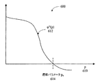
いくつかの従来のアプローチでは、伝導性cを関数c(p)=φ’(p)/pと定義することにより、異方性拡散PDEに基づいてアプローチを拡張するが、この関数はφ(0)=0である微分可能非減少関数φ(p)に対応する。(φ(p)が内部エネルギー汎関数の内部エネルギー密度関数である場合、最小エネルギー問題においてオイラーラグランジュ方程式を解くための最急降下法は、外部エネルギーの離散公式に対する異方性拡散PDEおよび外部エネルギーの連続公式に対する拡散反応PDEが得られる)。p610の関数としての関数φ”(p)612(二重引用符”は二階導関数であることを示す)は、図6に例示されており、ただし、p=|∇u|は空間グラディエントuの大きさであり、ある時点における異方性拡散方程式の(未知の)解である。内部エネルギー密度関数に対するポピュラーな選択の1つとして、φ(p)=pがある。この選択について、対応する伝導性関数はc(p)=1/pである。p610の小さな値は、画像内容の高速拡散に対応する。その結果、画像テクスチャおよび軽度の画像エッジなどの画像詳細は、画像処理中に失われる可能性がある。p610の大きな値は、画像内容の中のエッジの鮮鋭化に対応する。これらの上下限の間に連続的な変化があるが、遷移パラメータp0614と呼ばれるゼロ交差は、2つの領域に分離する。
Some conventional approaches extend the approach based on anisotropic diffusion PDE by defining the conductivity c as the function c (p) = φ ′ (p) / p, but this function is φ ( 0) = 0 corresponding to the differentiable non-decreasing function φ (p). (When φ (p) is the internal energy density function of the internal energy functional, the steepest descent method for solving the Euler-Lagrange equation in the minimum energy problem is the anisotropic diffusion PDE for the discrete formula of external energy and the external energy A diffusion reaction PDE for the continuous formula is obtained). The function φ ″ (p) 612 (indicating that the double quotation mark is a second derivative) as a function of
図7は、画像エッジ上のある1つの点における横方向単位ベクトルt710および法線方向単位ベクトルn712を含む、局所座標700を例示するブロック図である。p=|∇u|(図6)が遷移パラメータp0614よりも大きい場合、鮮鋭化は、法線方向単位ベクトルn712にそった逆方向拡散のため生じる。法線方向単位ベクトルn712は、(未知の)解uのグラディエントの方向の単位ベクトルであり、横方向単位ベクトルt710は、右手の法則に従ってnに直交する。p=|∇u|(図6)が遷移パラメータp0614よりも小さい場合(図6)、最小の拡散が法線方向単位ベクトルn712にそって生じ、したがってぼけはあまり見えない。遷移パラメータp0614を適切に選択する場合、画像ノイズを除去または低減しつつ、画像鮮鋭度を維持するか、または高めることができる。しかし、すでに説明されているように、異方性拡散PDEに基づくこれらのモデルおよび他のモデルでは、複雑度が増しており、また数値解を求めるために使用される計算量が増える。典型的には、非線形異方性拡散PDEのこれらの解および他の解では、何回もの反復または多段画像処理を使用する。例えば、一定の時間ステップパラメータΔtを使用してPDEを離散化し、非線形差分方程式をたてることができる。ノイズを含む入力画像は、PDEの初期条件として使用される。「クリーンな」出力画像に対応する、数値解は、典型的には、多数の反復ステップまたは演算(最大100回またはそれ以上)を伴い、また反復プロセスを終了させるための停止時間のアドホックな選択に依存する。
FIG. 7 is a block diagram illustrating
後述のCDFの微分では、異方性拡散PDEが離散化される。他の実施形態では、拡散反応PDEなどの、関係する非線形PDEは、離散化することができる。ノイズを含む画像を初期条件として使用する。伝導性関数c(p)は、p=|∇u|の関数として定義される。例示的な実施形態では、伝導性関数は The anisotropic diffusion PDE is discretized in the later-described differentiation of the CDF. In other embodiments, related non-linear PDEs, such as diffusion reaction PDEs, can be discretized. An image containing noise is used as an initial condition. The conductivity function c (p) is defined as a function of p = | ∇u |. In an exemplary embodiment, the conductivity function is
PDEを数値的に解く代わりに、時間パラメータをピクセル依存スケールにマッピングする。このスケールを使用すると、停止時刻を使用しなくて済み、画像処理を1パスで実行できるようになる。例示的な一実施形態として、3×3フィルタウィンドウを考える。3×5、5×5、および7×7のフィルタウィンドウに対する結果も示される。当業者には明らかなように、フィルタサイズの大きなCDFだけでなく、三次元CDFも構築できる。 Instead of numerically solving the PDE, the time parameter is mapped to a pixel dependent scale. When this scale is used, it is not necessary to use the stop time, and image processing can be executed in one pass. As an exemplary embodiment, consider a 3 × 3 filter window. Results for 3x5, 5x5, and 7x7 filter windows are also shown. As will be apparent to those skilled in the art, not only a CDF with a large filter size but also a three-dimensional CDF can be constructed.
以下で求められる、CDFは、水平と垂直の両方向に有限フィルタ長を持つ(CDFの三次元実施形態は、第3方向にも有限長を持つ)。フィルタ処理された画像の少なくとも1つの部分集合内のそれぞれのピクセルは、それ独自のCDFフィルタを持つことができる。いくつかの実施形態では、これらのCDFフィルタは、水平方向および垂直方向に対称的な形状を持つウィンドウに対応する。ウィンドウは、(2m+1)×(2n+1)個のピクセルに対応しうるが、mおよびnは、任意の正整数である(三次元実施形態については、第3の方向の次元はqである)。例示的な一実施形態では、mおよびnは、それぞれ1から50までの範囲の正整数である(また、三次元実施形態については、qは、1から10までの範囲の正整数とすることができる)。いくつかの実施形態では、mは、nに等しい、つまり、ウィンドウは正方形とすることができる。いくつかの実施形態では、ウィンドウは長方形とすることができる。いくつかの実施形態では、ウィンドウは、偶数個×奇数個のピクセルまたは奇数個×偶数個のピクセルなどの非対称的形状とすることもできる。CDFは、上述の形式(formalism)よりもいくつか多い追加の機能を組み込む。このプロセスでは、画像処理は、単一パス、つまり、非反復的方法で実装することができる。 The CDF determined below has a finite filter length in both the horizontal and vertical directions (a three-dimensional embodiment of the CDF also has a finite length in the third direction). Each pixel in at least one subset of the filtered image can have its own CDF filter. In some embodiments, these CDF filters correspond to windows having symmetrical shapes in the horizontal and vertical directions. The window may correspond to (2m + 1) × (2n + 1) pixels, but m and n are any positive integers (for the three-dimensional embodiment, the dimension in the third direction is q). In one exemplary embodiment, m and n are each a positive integer in the range of 1 to 50 (and q is a positive integer in the range of 1 to 10 for the three-dimensional embodiment. Is possible). In some embodiments, m is equal to n, that is, the window can be square. In some embodiments, the window can be rectangular. In some embodiments, the window may have an asymmetric shape, such as an even number × odd number of pixels or an odd number × even number of pixels. CDF incorporates several additional functions over the formalism described above. In this process, image processing can be implemented in a single pass, that is, in a non-iterative manner.
CDFがより効果的であるためには、いくつかの実施形態において、ウィンドウ内のエントリは任意のゼロフィルタ係数または重みを持たなくてもよい。例えば、3×3フィルタを設計する場合、フィルタ行列 In order for CDF to be more effective, in some embodiments the entries in the window may not have any zero filter coefficients or weights. For example, when designing a 3 × 3 filter, the filter matrix
未知の解uの空間グラディエントの大きさの関数である伝導性関数c(|∇u|)の使用は、難題をもたらす可能性がある。特に、未知の解uは、入力画像データを最初に表すために使用されるので、これは、ノイズで汚染されている場合があり、uの空間グラディエント値は不正確で、強い変動を示すことがある。これに対処するために、離散伝導性関数における入力画像の空間グラディエントは、水平および/または垂直方向の入力画像のウェーブレット変換により置き換えることができる。他の実施形態では、伝導性関数における入力画像の空間グラディエントは、グラディエント演算が適用される前に、(未知の)解uに対しガウス畳み込みが実行されるように修正することができる。CDFは1パスで適用することができるが、CDFが複数回適用される場合、後におこる反復は、フィルタ処理された画像がもはやノイズを含まないため、上述の伝導性関数c(|∇u|)の修正版を使用しても使用しなくてもよい。 The use of the conductivity function c (| ∇u |), which is a function of the magnitude of the spatial gradient of the unknown solution u, can pose a challenge. In particular, since the unknown solution u is used to initially represent the input image data, it may be contaminated with noise, and u's spatial gradient value is inaccurate and exhibits strong fluctuations. There is. To address this, the spatial gradient of the input image in the discrete conductivity function can be replaced by a wavelet transform of the horizontal and / or vertical input image. In other embodiments, the spatial gradient of the input image in the conductivity function can be modified so that a Gaussian convolution is performed on the (unknown) solution u before the gradient operation is applied. CDF can be applied in one pass, but if CDF is applied multiple times, subsequent iterations will result in the above-described conductivity function c (| 上述 u | ) Or a modified version of).
それに加えて、時間−スケール変換(時間−スケールマッピングともいう)が導入される。これらの変換は、異方性拡散PDEの離散化における定数時間ステップパラメータΔt(これ以降λで表す)を、1つまたは複数のピクセル依存スケールにマッピングする。これらのスケールは、ノイズを含む入力画像内の中心ピクセルとともにフィルタウィンドウ内の隣接ピクセルの関数として公式化される。以下で詳しく説明されるように、時間−スケール変換は、画像平滑化/鮮鋭化調整を決定する1つまたは複数のパラメータに関連付けられる。1つまたは複数のパラメータを使用して、いくつかの異なる画像エッジの鮮鋭度を実質的に変えずに、感じの良いぼけ効果を生み出すことができる。時間−スケール変換を使用することで、異方性拡散または他のPDEを数値的に解かずに、CDFのフィルタカーネルを構築することができる。その結果、CDFを適用して、画像からノイズを除去または低減する場合、反復ステップおよび停止時刻kは必要ない。 In addition, time-scale conversion (also called time-scale mapping) is introduced. These transformations map the constant time step parameter Δt (hereinafter denoted λ) in the discretization of anisotropic diffusion PDE to one or more pixel dependent scales. These scales are formulated as a function of neighboring pixels in the filter window along with the central pixel in the noisy input image. As described in detail below, the time-scale transformation is associated with one or more parameters that determine the image smoothing / sharpening adjustment. One or more parameters can be used to produce a pleasing blur effect without substantially changing the sharpness of several different image edges. Using time-scale transformation, a CDF filter kernel can be constructed without numerically solving anisotropic diffusion or other PDEs. As a result, when applying CDF to remove or reduce noise from an image, iterative steps and stop times k are not necessary.
離散化の後、異方性拡散PDEは、 After discretization, the anisotropic diffusion PDE is
![]()
![]()
![]()
![]()
![]()
![]()
3×3フィルタウィンドウを持つCDFに対するフィルタカーネルを構築するために、北東(NE)、南東(SE)、南西(SW)、および北西(NW)の方向の隣接ピクセルの第2の集合も離散化される。差分方程式は、これら4つの追加のピクセルを含むように拡張できる。 A second set of adjacent pixels in the northeast (NE), southeast (SE), southwest (SW), and northwest (NW) directions is also discretized to build a filter kernel for the CDF with a 3x3 filter window. Is done. The difference equation can be extended to include these four additional pixels.
![]()
![]()
同様に、3×5、5×5、および7×7のウィンドウに対するCDFを決定または構築することができる。3×5ウィンドウでは、CDFは、
次に、ウェーブレット変換の実施形態に注目する。図8は、すでに説明されているウェーブレット変換を含む、フィルタカーネルを決定または構築するプロセスの一実施形態800を例示する流れ図である。画像uが受信される(810)。uとローパスフィルタLとの畳み込みを使用して、フィルタ処理された画像(L*u)が生成される(812)。いくつかの実施形態では、水平方向および/または垂直方向のLの重み総和は、有限値を持つことができる。(L*u)の差分演算は、水平または垂直方向のuのウェーブレット変換である。このウェーブレット変換が2つの方向のうちの1つで適用されない場合、代わりにその方向に1階差分演算を使用することができる。いくつかの実施形態では、他のウェーブレット変換を使用することができる。ウェーブレット変換(|∂(L*u)|)の大きさ、または1階差分が、決定される(814)。この値は、それぞれの伝導性レベルIに合わせて、量子化することができる(816)。ウェーブレット変換(1階差分演算の代わり)は、ノイズを含む入力画像に使用することができる。これらの結果は、対応する伝導性c(i*2m−n)にマッピングされる(818)。流れ図500は、それよりも少ない演算または追加の演算を含むことができる。更に、2つまたはそれ以上の演算を組み合わせること、および/または演算の順序を変更することができる。
Next, attention is focused on embodiments of wavelet transform. FIG. 8 is a flow diagram illustrating one
図8に例示されているように、ノイズを含む入力画像を修正して、伝導性関数に関連付けられている離散伝導性要素を生成することができる。例示的な一実施形態では、離散グラディエント演算に対する1階差分の代わりに、例えば、レベル/伝導性チャートとともにuのローパスフィルタリングの差分演算を適用することにより、ウェーブレット変換を実装することができる。例示的な一実施形態では、c(|∇u|)の空間グラディエントを、uの何らかの離散スプライン−ウェーブレット変換により置き換えられる。例えば、c(|∇u|)における∇uは、∂(L*u)≡Wuで置き換えることができるが、ただし、Lは、何らかの望ましいカージナルBスプラインに関連付けられているローパスフィルタであり、表記*は、標準畳み込み演算を表し、Wuは、離散ウェーブレット変換演算を表す。演算LおよびWは、ノイズを含む入力画像uの中心ピクセルに関して、それぞれの(地理的)方向で決定することができる。例えば、
WEui,j=∂E(L*u)i,j、WSui,j=∂S(L*u)i,j、WWui,j=∂W(L*u)i,j、WNui,j=∂N(L*u)i,j,
WNEui,j=∂NE(L*u)i,j、WSEui,j=∂SE(L*u)i,j、WSWui,j=∂SW(L*u)i,j、WNWui,j=∂NW(L*u)i,j
である。他の実施形態では、所望の離散化を得るために差分演算が適用される前に、ガウス畳み込みをuのローパスフィルタとして使用することができる。
As illustrated in FIG. 8, the noisy input image can be modified to produce discrete conductive elements associated with the conductivity function. In an exemplary embodiment, wavelet transforms can be implemented by applying u low-pass filtering difference operations together with a level / conductivity chart, for example, instead of first-order differences for discrete gradient operations. In one exemplary embodiment, the spatial gradient of c (| ∇u |) is replaced by some discrete spline-wavelet transform of u. For example, ∇u in c (| ∇u |) can be replaced by ∂ (L * u) ≡Wu, where L is a low-pass filter associated with some desired cardinal B-spline, and notation * Represents a standard convolution operation, and Wu represents a discrete wavelet transform operation. The operations L and W can be determined in the respective (geographic) directions with respect to the central pixel of the input image u containing noise. For example,
W E i, j = ∂ E (L * u) i, j , W S u i, j = ∂ S (L * u) i, j , W W u i, j = ∂ W (L * u) i, j , W N u i, j = ∂ N (L * u) i, j ,
W NE u i, j = ∂ NE (L * u) i, j , W SE u i, j = ∂ SE (L * u) i, j , W SW u i, j = ∂ SW (L * u) i, j , W NW u i, j = ∂ NW (L * u) i, j
It is. In other embodiments, Gaussian convolution can be used as a low pass filter for u before the difference operation is applied to obtain the desired discretization.
表1は、伝導性レベル/伝導性関数チャートの一実施形態を例示しており、これは、伝導性レベルを離散伝導性要素の値に関連付ける。入力画像がチャネル毎にrビットのグレーレベルを持ち(典型的には、r=8)、伝導性レベルがsビットに量子化される場合(sは、r以下であり、典型的には1から8までの範囲である)、p=|∇u|の範囲はシーケンス[0,...,2r−1]である。このシーケンスが、2r−s[0,...,2s−1]に量子化される場合、伝導性関数c(p)は、[0,...,2s−1]を[c(0),c(2r−s),...,c(2r−s(2s−1))]にマッピングする。前述のように、伝導性関数の典型的な実施例は、c(p)=e−p/K、 Table 1 illustrates one embodiment of a conductivity level / conductivity function chart, which relates the conductivity level to the value of the discrete conductivity element. If the input image has a gray level of r bits per channel (typically r = 8) and the conductivity level is quantized to s bits (s is less than r, typically 1 P = | ∇u | is a sequence [0,. . . , 2 r −1]. This sequence becomes 2 r−s [0,. . . , 2 s −1], the conductivity function c (p) is [0,. . . , 2 s −1] to [c (0), c (2 r−s ),. . . , C (2 r−s (2 s −1))]. As mentioned above, an exemplary embodiment of the conductivity function is c (p) = ep− p / K ,
次に、CDFの決定または構築およびその使用を例示する追加の実施形態に注目する。図9は、画像、画像タイル、またはサイズ5×5のPもしくはBフレーム(映像圧縮における)のマクロブロックなどの画像ブロック内の、ピクセルの集合900を例示するブロック図である。図10、11、および12は、5×5画像タイル内のノイズを除去または低減するため、それぞれ、A、B、およびCのラベルが付いているピクセルの集合に対する最大3×3までのウィンドウを持つ対応する二次元CDFの構築を例示している。図9のピクセルの集合Aは、図10のコーナーピクセルu00に対するCDFの構築および適用を例示している。図9のピクセルの集合Bは、図11の境界ピクセルui0に対するCDFの構築および適用を例示している。図9のピクセルの集合Cは、図12の内部中心ピクセルuijに対するCDFの構築および適用を例示している。ラベルAが付いているピクセルの集合について、中心ピクセルは、ピクセル900の集合内のコーナーピクセルである。したがって、これは、その隣接要素の3つのピクセル値に基づく値で置き換えられる。ラベルBが付いているピクセルの集合では、中心ピクセルは、ピクセルの集合900内の境界ピクセルであり、その隣接要素の5つのピクセル値に基づく値で置き換えられる。ラベルCが付いているピクセルの集合では、中心ピクセルは、ピクセルの集合900内の内部ピクセルであり、その隣接要素の8つのピクセル値に基づく値で置き換えられる。
Attention is now directed to additional embodiments that illustrate CDF determination or construction and its use. FIG. 9 is a block diagram illustrating a
図10は、CDF用のフィルタカーネルを構築し、該CDFをコーナーピクセルu00に適用するプロセスの一実施形態1000を例示する流れ図である。1階差分演算がピクセルの集合1010に適用されて要素1012を生成し、これが、レベルおよび伝導性チャート(表1に示されているようなもの)を使用してマッピングされ、離散伝導性要素1014を生成する。フィルタカーネル1016は、離散伝導性要素1014の定義済み部分集合に平滑化および鮮鋭化パラメータであるαおよびμを乗算することにより、構築される。例示的な実施形態では、αは約0.0625から1までの範囲であり、μは、ほぼ0と1の間にある。例えば、α=0.25およびμ=0.0625である。要素1016は、ピクセルの集合1010と要素毎に乗算され1022、要素1024を生成する。要素1024は、総和され(1025)、値r0,01026を生成する。要素1016は、さらに、総和され1018、正規化値とも呼ばれる、時間スケール値k0,01020を生成する。値r0,0と時間スケール値k0,01020との比1027は、対応する出力フィルタ処理ピクセル値1028である。
Figure 10 constructs a filter kernel for CDF, a flow diagram illustrating an
図11は、CDF用のフィルタカーネルを構築し、該CDFを境界ピクセルui0に適用するプロセスの一実施形態1100を例示する流れ図である。1階差分演算がピクセルの集合1110に適用されて要素1112を生成し、これが、レベルおよび伝導性チャート(表1に示されているようなもの)を使用してマッピングされ、離散伝導性要素1114を生成する。フィルタカーネル1116は、離散伝導性要素1114の定義済み部分集合に平滑化および鮮鋭化パラメータであるαおよびμを乗算することにより、構築される。要素1116は、ピクセルの集合1110と要素毎に乗算され1122、要素1124を生成する。要素1124は、総和され(1125)、値ri,01126を生成する。要素1116は、総和され1118、正規化値とも呼ばれる、時間スケール値ki,01120を生成する。値ri,0と時間スケール値ki,01120との比1127は、入力ピクセル値ui,0に対応する出力フィルタ処理ピクセル値1128である。
FIG. 11 is a flow diagram illustrating one
図12は、CDF用のフィルタカーネルを構築し、該CDFを内部(中心)ピクセルuijに適用するプロセスの一実施形態1200を例示する流れ図である。1階差分演算がピクセルの集合1210に適用されて要素1212を生成し、これが、レベルおよび伝導性チャート(表1に示されているようなもの)を使用してマッピングされ、離散伝導性要素1214を生成する。フィルタカーネル1216は、離散伝導性要素1214の定義済み部分集合に平滑化および鮮鋭化パラメータであるαおよびμを乗算することにより、構築される。フィルタカーネル1216の要素は、ピクセルの集合1210と要素毎に乗算され1222、要素1224を生成する。要素1224は、総和され(1225)、値ri,j1226を生成する。要素1216は、総和され(1218)、時間スケール値ki,j1220を生成する。値ri,j1226と時間スケール値ki,j1220との比1227を計算して、入力ピクセル値ui,jに対応する出力フィルタ処理ピクセル値1228(ri,j/ki,j)を生成する。
FIG. 12 is a flow diagram illustrating one
図13は、CDF用のフィルタカーネルを構築し使用するプロセスの一実施形態1300を例示する流れ図である。1階差分演算が、中心ピクセルが(画像タイルまたは配列内の)画像エッジ上に配置されているピクセルの集合1310に適用され、要素1311を生成する。この実施例におけるピクセルの集合1310は、画像の明暗領域の間の垂直エッジを表す。要素1311は、対応する伝導性レベルに量子化されて、離散伝導性関数値1312を生成し、レベルおよび伝導性チャート(表1に示されているようなもの)を使用してマッピングされ、要素1314を生成する。要素1314の定義済み部分集合に平滑化および鮮鋭化パラメータであるαおよびμを乗算し、フィルタカーネル1316を生成する。ピクセルの集合1310は、フィルタカーネル1316と要素毎に乗算され(1322)、要素1324を生成する。要素1324は、総和され(1325)、値ri,j=28.9316(1326)を生成する。フィルタカーネル要素1316は、総和され(1318)、時間スケール値ki,j=3.0051(1320)を生成する。値ri,j1326と時間スケール値ki,j1320との比1327を計算して、入力ピクセル値ui,jに対応する出力フィルタ処理ピクセル値1328(ri,j/ki,j=9.6275)を生成する。この実施例では、フィルタ処理されたピクセル1328は、値10に量子化することができる。実施形態1300では、α=0.5、μ=0.25、K=50であり、伝導性関数は、
FIG. 13 is a flow diagram illustrating one
図14は、CDF用のフィルタカーネルを構築し使用するプロセスの一実施形態1400を例示する流れ図である。1階差分演算が、中心ピクセルが画像エッジ上にないピクセルの集合1410に適用されて、要素1411を生成し、対応する伝導性レベルに量子化されて、離散伝導性関数値1412を生成し、レベルおよび伝導性チャート(表1に示されているようなもの)を使用してマッピングされ、要素1414を生成する。要素1414の定義済み部分集合に平滑化および鮮鋭化パラメータであるαおよびμを乗算し、要素毎に(または項毎に)乗算して、フィルタカーネル(CDF)1416を生成する。初期中心ピクセル=230を持つ入力画像ブロック1410は、CDF1416により要素毎に乗算され1422、要素1424を生成する。要素1424が、総和され(1425)、値ri,j(921.826)1426を生成し、CDFの要素1416が、総和され1418、時間スケール値ki,j(3.995)1420を生成する。値ri,j1426と時間スケール値ki,j1420との比1427を計算して、入力ピクセル値ui,jに対応する出力フィルタ処理ピクセル値(230.745)1428を生成する。フィルタ処理されたピクセル1428は、値231に量子化することができる。実施形態1400では、α=0.5、μ=0.25、K=50であり、伝導性関数は、
FIG. 14 is a flow diagram illustrating one
CDFは、画像内のノイズを除去または低減するための前置符号器として使用することができ、該画像は、ビデオシーケンスのIフレームであってよい。例えば、図15の実施形態1500では、画像の8×8タイル1512またはIフレームは、CDF1514により処理される。画像のフィルタ処理された画像タイルまたはIフレーム1516は、符号器1518に送られる。符号器1518は、離散コサイン変換(DCT)1520、量子化1522、およびエントロピー符号化1524を含む。より小さなビットレートを持つ符号化されたビットストリーム1526が出力される。流れ図1500は、それよりも少ない演算または追加の演算を含むことができる。更に、2つまたはそれ以上の演算を組み合わせること、および/または演算の順序を変更することができる。
CDF can be used as a precoder to remove or reduce noise in an image, which can be an I frame of a video sequence. For example, in the
それぞれのCDFは、MJPEG、MPEG−1、2、4、7、およびH263、AVC、またはH264などの既存の符号器内に、前置符号器として組み込むことができる。それぞれのCDFまたはCDFの集合を使用して生成されるフィルタ処理済み画像は、既存の復号器と互換性を持つことができる。CDF用のそれぞれのフィルタカーネルを使用して、動き推定補償においてIフレーム、Pフレーム、および/またはマクロブロックをクリーンアップすることができる。図16は、そのようなプロセスの一実施形態1600を例示するブロック図である。フィルタカーネル1612は、動き補償Pフレーム1608に適用され、フィルタ処理済みIフレーム1610(これは図15に例示されていた)から差し引かれる1614。DCT1618および量子化1620が、結果として得られるフィルタ処理済みB/Pフレーム1616に適用される。
Each CDF can be incorporated as a pre-encoder in existing encoders such as MJPEG, MPEG-1, 2, 4, 7, and H263, AVC, or H264. Filtered images generated using each CDF or set of CDFs can be compatible with existing decoders. Each filter kernel for CDF can be used to clean up I-frames, P-frames, and / or macroblocks in motion estimation compensation. FIG. 16 is a block diagram illustrating one
図17は、フレーム1712などのデジタル画像または画像タイルをフィルタ処理する1718、特に動き補償用の16×16マクロブロックをフィルタ処理する1718、プロセスの一実施形態1700を例示するブロック図である。いくつかの実施形態では、前のIまたはPフレーム1710を使用して、動きベクトル1716_1を決定し、および/またはその後のPまたはBフレーム1714を使用して、動きベクトル1716_2を決定する。前者は、フレーム1712がPフレームである場合に発生し、後者は、フレーム1712がBフレームである場合に発生しうる。
FIG. 17 is a block diagram illustrating an
図18は、画像立方体と呼ばれる、三次元デジタル画像をフィルタ処理または前置符号化するプロセス1800の一実施形態を例示する流れ図である。プロセス1800において、動き推定および補償がPフレームおよびBフレーム(図17に例示されていた)に適用されビデオフレーム1810、1812、1814を作成した後、三次元CDFを生成して適用し1816、3つの連続するビデオフレーム1810、1812、1814に基づく立方体などの画像立方体から、雑音を低減または除去する。MJEPなどのいくつかの実施形態では、ビデオフレーム1810、1812、および1814はIフレームである。いくつかの実施形態では、CDF用のフィルタカーネルは、画像立方体を構成するI、P、および/またはBフレームの混合に適用することができる。
FIG. 18 is a flow diagram illustrating one embodiment of a
CDF用のフィルタカーネルを、1つまたは複数の画像、または1つまたは複数の画像の1つまたは複数の部分集合に適用し、画像エッジに関連するテクスチャおよび/または空間周波数などの画像内容をほぼ変化しないようにしつつ、ノイズを低減または除去することができる。これは、図19に例示されており、フィルタ処理されていないデジタル画像および本発明の一実施形態を使用動きベクトルして生成されたフィルタ処理済みデジタル画像を示している。 Apply a filter kernel for CDF to one or more images, or one or more subsets of one or more images, to approximate image content such as texture and / or spatial frequency associated with image edges Noise can be reduced or eliminated while not changing. This is illustrated in FIG. 19 and shows an unfiltered digital image and a filtered digital image generated using motion vectors using one embodiment of the present invention.
本発明の特定の実施形態の前記説明は、例示および説明を目的として提示されている。これらは、網羅的(exhaustive)であること、または本発明を開示した正確な形態だけに限ることを意図されていない。むしろ、上記の教示を鑑みて多くの修正および変更が可能であることが理解されるであろう。これらの実施形態は、本発明の原理およびその実用的用途を最もよく説明するために選択され、記述されており、それにより、当業者は、考え付く特定の用途に適しているような様々な修正とともに、本発明および様々な実施形態を最もよく利用することができる。 The foregoing descriptions of specific embodiments of the present invention have been presented for purposes of illustration and description. They are not intended to be exhaustive or to limit the invention to the precise forms disclosed. Rather, it will be appreciated that many modifications and variations are possible in light of the above teaching. These embodiments have been chosen and described in order to best explain the principles of the invention and its practical application, thereby enabling those skilled in the art to make various modifications suitable to the particular application envisaged. In addition, the present invention and various embodiments can be best utilized.
Claims (20)
前記それぞれのピクセルに対しピクセル依存フィルタカーネルを生成することと、第1のフィルタリングパラメータに従って、前記デジタル画像内のノイズを平滑化し、前記デジタル画像内の画像エッジに関連する空間周波数を保存するために、前記それぞれのピクセルに対し前記フィルタカーネルを非反復的に適用することを含み、
前記ピクセルの集合内のそれぞれのピクセルに対する前記フィルタカーネルは、それぞれのピクセル及び隣接ピクセルの第1の集合の関数であり、非反復的なノイズフィルタリングを可能とする前記それぞれのピクセルに対する閉形式を持ち、かつ前記隣接ピクセルの第1の集合からの寄与因子を含み、また前記ピクセルの集合内のそれぞれのピクセルに対する前記フィルタカーネルは、前記それぞれのピクセルに対する前記フィルタカーネルの要素の和を求めることによって生成される内容依存時間スケール値に基づいて正規化される、方法。A method of filtering a digital image, for each pixel in the set of pixels of the digital image,
Generating a pixel dependent filter kernel for each respective pixel and smoothing noise in the digital image according to a first filtering parameter and preserving a spatial frequency associated with an image edge in the digital image Non-iteratively applying the filter kernel to the respective pixels;
The filter kernel for each pixel in the set of pixels is a function of the first set of respective pixels and neighboring pixels and has a closed form for each pixel that allows non-repetitive noise filtering. and produced by the comprises a contribution factor of the first set of neighboring pixels, and the filter kernel for each pixel in said set of pixels, obtaining the sum of the elements of the filter kernel for said each pixel Normalized based on a content-dependent time scale value .
フィルタ処理されたピクセルは、
Mは閉形式配列であり、該閉形式配列は、前記それぞれのピクセルの関数であり、ウィンドウサイズが(2m+1)×(2n+1)であり、mおよびnは正整数であり、Mは、前記ウィンドウ内の隣接ピクセルの集合からの寄与因子を含み、Uは、ピクセルの前記集合内の部分配列であり、前記それぞれのピクセルと隣接ピクセルの前記集合とを含み、
前記内容依存正規化因子γは、M内の前記要素の和を求めることによって生成される内容依存時間スケール値を含む、方法。A method of filtering a digital image, according to filtering parameters, for smoothing noise in the digital image and preserving spatial frequencies associated with image edges in the digital image, Non-iteratively applying each pixel dependent filter kernel to the pixel,
The filtered pixels are
M is a closed format array, the closed format array is a function of the respective pixels, the window size is (2m + 1) × (2n + 1), m and n are positive integers, and M is the window And U is a sub-array within the set of pixels, including the respective pixel and the set of adjacent pixels,
The content-dependent normalization factor γ comprises a content-dependent time scale value generated by determining the sum of the elements in M.
メモリと、
プロセッサと、
前記メモリ内に格納され、前記プロセッサにより実行されるように構成された1つまたは複数のプログラムとを備え、前記1つまたは複数のプログラムは、
前記デジタル画像のピクセルの集合内のそれぞれのピクセルに対して、
前記それぞれのピクセルに対するピクセル依存フィルタカーネルを生成し、かつフィルタリングパラメータに従って、前記デジタル画像内のノイズを平滑化し、前記デジタル画像内の画像エッジに関連する空間周波数を保存するために、前記それぞれのピクセルに対し前記フィルタカーネルを非反復的に適用する命令を含み、
前記ピクセルの集合内のそれぞれのピクセルに対する前記フィルタカーネルは、それぞれのピクセル及び隣接ピクセルの第1の集合の関数であり、前記それぞれのピクセルに対する閉形式を持ち、かつ前記隣接ピクセルの第1の集合からの寄与因子を含み、また前記それぞれのピクセルに対する前記フィルタカーネルは、前記それぞれのピクセルに対する前記フィルタカーネルの要素の和を求めることによって生成される内容依存時間スケール値に基づいて正規化される、デジタル画像処理プロセッサ。A digital image processor,
Memory,
A processor;
One or more programs stored in the memory and configured to be executed by the processor, the one or more programs comprising:
For each pixel in the set of pixels of the digital image,
Generating a pixel dependent filter kernel for the respective pixel and smoothing noise in the digital image according to filtering parameters and preserving a spatial frequency associated with an image edge in the digital image; Including instructions for applying the filter kernel non-iteratively to
The filter kernel for each pixel in the set of pixels is a first function of the set of the respective pixel and neighboring pixels, the first set of the have closed form for each pixel, and the neighboring pixels comprises a contribution factor from, also the filter kernel for the respective pixels are normalized on the basis of the content dependent time scale value generated by summing the elements of the filter kernel for said each pixel, Digital image processor.
前記デジタル画像のピクセルの集合内のそれぞれのピクセルに対して、
前記それぞれのピクセルに対するピクセル依存フィルタカーネルを生成し、かつフィルタリングパラメータに従って、前記デジタル画像内のノイズを平滑化し、前記デジタル画像内の画像エッジに関連する空間周波数を保存するために、前記それぞれのピクセルに対し前記フィルタカーネルを非反復的に適用することを実行させ、
前記ピクセルの集合内のそれぞれのピクセルに対する前記フィルタカーネルは、それぞれのピクセル及び隣接ピクセルの第1の集合の関数であり、前記それぞれのピクセルに対する閉形式を持ち、かつ前記隣接ピクセルの第1の集合からの寄与因子を含み、また前記ピクセルの集合内のそれぞれのピクセルに対する前記フィルタカーネルは、前記それぞれのピクセルに対する前記フィルタカーネルの要素の和を求めることによって生成される内容依存時間スケール値に基づいて正規化される、コンピュータプログラム。A computer program for digital image filtering, when executed by a computer device,
For each pixel in the set of pixels of the digital image,
Generating a pixel dependent filter kernel for the respective pixel and smoothing noise in the digital image according to filtering parameters and preserving a spatial frequency associated with an image edge in the digital image; To apply the filter kernel non-iteratively ,
The filter kernel for each pixel in the set of pixels is a function of the first set of respective pixels and neighboring pixels, has a closed form for the respective pixels, and the first set of neighboring pixels And the filter kernel for each pixel in the set of pixels is based on a content-dependent time scale value generated by determining a sum of elements of the filter kernel for the respective pixel. A computer program that is normalized.
メモリ手段と、
プロセッサ手段と、
プログラムメカニズムとを備え、前記プログラムメカニズムは、前記メモリ手段内に格納され、前記プロセッサ手段により実行されるように構成されており、前記プログラムメカニズムは、
前記デジタル画像のピクセルの集合内のそれぞれのピクセルに対して、
前記それぞれのピクセルに対するピクセル依存フィルタカーネルを生成し、かつフィルタリングパラメータに従って、前記デジタル画像内のノイズを平滑化し、前記デジタル画像内の画像エッジに関連する空間周波数を保存するために、前記それぞれのピクセルに対し前記フィルタカーネルを非反復的に適用する命令を含み、
前記ピクセルの集合内のそれぞれのピクセルに対する前記フィルタカーネルは、それぞれのピクセル及び隣接ピクセルの第1の集合の関数であり、前記それぞれのピクセルに対する閉形式を持ち、かつ前記隣接ピクセルの第1の集合からの寄与因子を含み、また前記ピクセルの集合内のそれぞれのピクセルに対する前記フィルタカーネルは、前記それぞれのピクセルに対する前記フィルタカーネルの要素の和を求めることによって生成される内容依存時間スケール値に基づいて正規化される、デジタル画像処理プロセッサ。A digital image processor,
Memory means;
Processor means;
A program mechanism, wherein the program mechanism is stored in the memory means and is configured to be executed by the processor means.
For each pixel in the set of pixels of the digital image,
Generating a pixel dependent filter kernel for the respective pixel and smoothing noise in the digital image according to filtering parameters and preserving a spatial frequency associated with an image edge in the digital image; Including instructions for applying the filter kernel non-iteratively to
The filter kernel for each pixel in the set of pixels is a first function of the set of the respective pixel and neighboring pixels, the first set of the have closed form for each pixel, and the neighboring pixels And the filter kernel for each pixel in the set of pixels is based on a content-dependent time scale value generated by determining a sum of elements of the filter kernel for the respective pixel. A digital image processor that is normalized .
Applications Claiming Priority (3)
| Application Number | Priority Date | Filing Date | Title |
|---|---|---|---|
| US57984004P | 2004-06-14 | 2004-06-14 | |
| US60/579,840 | 2004-06-14 | ||
| PCT/US2005/021099 WO2005124664A2 (en) | 2004-06-14 | 2005-06-14 | Image clean-up and pre-coding |
Publications (3)
| Publication Number | Publication Date |
|---|---|
| JP2008503192A JP2008503192A (en) | 2008-01-31 |
| JP2008503192A5 JP2008503192A5 (en) | 2008-07-31 |
| JP5007228B2 true JP5007228B2 (en) | 2012-08-22 |
Family
ID=35510414
Family Applications (1)
| Application Number | Title | Priority Date | Filing Date |
|---|---|---|---|
| JP2007527809A Expired - Fee Related JP5007228B2 (en) | 2004-06-14 | 2005-06-14 | Image cleanup and precoding |
Country Status (5)
| Country | Link |
|---|---|
| US (1) | US7570832B2 (en) |
| JP (1) | JP5007228B2 (en) |
| CN (1) | CN100524346C (en) |
| HK (1) | HK1111494A1 (en) |
| WO (1) | WO2005124664A2 (en) |
Families Citing this family (52)
| Publication number | Priority date | Publication date | Assignee | Title |
|---|---|---|---|---|
| US8077998B2 (en) * | 2004-01-05 | 2011-12-13 | Production Resource Group, Llc | Reduced complexity and blur technique for an electronic lighting system |
| US7636489B2 (en) * | 2004-04-16 | 2009-12-22 | Apple Inc. | Blur computation algorithm |
| CN100563342C (en) * | 2004-06-25 | 2009-11-25 | 松下电器产业株式会社 | Image coding method and image decoding method |
| US8548055B2 (en) * | 2005-03-10 | 2013-10-01 | Qualcomm Incorporated | Encoding of multimedia data |
| US7613346B2 (en) | 2005-05-27 | 2009-11-03 | Ati Technologies, Inc. | Compositing in multiple video processing unit (VPU) systems |
| US7436188B2 (en) * | 2005-08-26 | 2008-10-14 | Step Communications Corporation | System and method for improving time domain processed sensor signals |
| US20070050441A1 (en) * | 2005-08-26 | 2007-03-01 | Step Communications Corporation,A Nevada Corporati | Method and apparatus for improving noise discrimination using attenuation factor |
| US7472041B2 (en) * | 2005-08-26 | 2008-12-30 | Step Communications Corporation | Method and apparatus for accommodating device and/or signal mismatch in a sensor array |
| US20070047743A1 (en) * | 2005-08-26 | 2007-03-01 | Step Communications Corporation, A Nevada Corporation | Method and apparatus for improving noise discrimination using enhanced phase difference value |
| US7619563B2 (en) | 2005-08-26 | 2009-11-17 | Step Communications Corporation | Beam former using phase difference enhancement |
| US20070047742A1 (en) * | 2005-08-26 | 2007-03-01 | Step Communications Corporation, A Nevada Corporation | Method and system for enhancing regional sensitivity noise discrimination |
| US7415372B2 (en) * | 2005-08-26 | 2008-08-19 | Step Communications Corporation | Method and apparatus for improving noise discrimination in multiple sensor pairs |
| WO2007029235A2 (en) * | 2005-09-05 | 2007-03-15 | Algosoft Limited | Automatic digital film and video restoration |
| US20080007747A1 (en) * | 2006-06-30 | 2008-01-10 | Fuji Photo Film Co., Ltd. | Method and apparatus for model based anisotropic diffusion |
| US7747045B2 (en) * | 2006-06-30 | 2010-06-29 | Fujifilm Corporation | Method and apparatus for diffusion based illumination normalization |
| CN101150304B (en) * | 2006-09-18 | 2010-11-03 | 中国医学科学院生物医学工程研究所 | Quick self-adapted noise elimination module based on FPGA design |
| WO2008065089A2 (en) * | 2006-11-27 | 2008-06-05 | Thomson Licensing | Video pre-processing device and method, motion estimation device and method |
| US8018504B2 (en) * | 2006-12-22 | 2011-09-13 | Eastman Kodak Company | Reduction of position dependent noise in a digital image |
| KR101379255B1 (en) * | 2007-04-06 | 2014-03-28 | 삼성전자주식회사 | Method and apparatus for encoding and decoding based on intra prediction using differential equation |
| US8306348B2 (en) * | 2007-04-24 | 2012-11-06 | DigitalOptics Corporation Europe Limited | Techniques for adjusting the effect of applying kernels to signals to achieve desired effect on signal |
| FR2919748B1 (en) * | 2007-08-03 | 2009-11-27 | Centre Nat Rech Scient | METHOD AND ASSOCIATED SYSTEM OF WAVELET WAVE TRANSFORMER FOR MASSIVE MULTIDIMENSIONAL DATA |
| US8086043B2 (en) * | 2007-12-21 | 2011-12-27 | Ati Technologies Ulc | System and method of image correlation based on image structure |
| KR100952340B1 (en) * | 2008-01-24 | 2010-04-09 | 에스케이 텔레콤주식회사 | Method and Apparatus for Determing Encoding Mode by Using Temporal and Spartial Complexity |
| US8948822B2 (en) * | 2008-04-23 | 2015-02-03 | Qualcomm Incorporated | Coordinating power management functions in a multi-media device |
| US8908763B2 (en) * | 2008-06-25 | 2014-12-09 | Qualcomm Incorporated | Fragmented reference in temporal compression for video coding |
| JP5279830B2 (en) * | 2008-07-14 | 2013-09-04 | シャープ株式会社 | Video signal processing device and video display device |
| US8948270B2 (en) * | 2008-08-19 | 2015-02-03 | Qualcomm Incorporated | Power and computational load management techniques in video processing |
| US8964828B2 (en) | 2008-08-19 | 2015-02-24 | Qualcomm Incorporated | Power and computational load management techniques in video processing |
| JP2010211552A (en) * | 2009-03-11 | 2010-09-24 | Rohm Co Ltd | Image processing method and computer program |
| EP2415015B1 (en) * | 2009-03-30 | 2015-08-12 | Telefonaktiebolaget LM Ericsson (publ) | Barcode processing |
| WO2010136547A1 (en) * | 2009-05-27 | 2010-12-02 | Canon Kabushiki Kaisha | Method and device for processing a digital signal |
| CN102667864B (en) * | 2009-10-26 | 2015-06-03 | 索尼计算机娱乐公司 | Image file generation device, image processing device, image file generation method, image processing method |
| US8295631B2 (en) * | 2010-01-29 | 2012-10-23 | Eastman Kodak Company | Iteratively denoising color filter array images |
| US8345130B2 (en) * | 2010-01-29 | 2013-01-01 | Eastman Kodak Company | Denoising CFA images using weighted pixel differences |
| US9071733B2 (en) | 2010-07-29 | 2015-06-30 | Valorbec, Societe En Commandite | Method for reducing image or video noise |
| US8787459B2 (en) * | 2010-11-09 | 2014-07-22 | Sony Computer Entertainment Inc. | Video coding methods and apparatus |
| US9807424B2 (en) * | 2011-01-10 | 2017-10-31 | Qualcomm Incorporated | Adaptive selection of region size for identification of samples in a transition zone for overlapped block motion compensation |
| US8798967B2 (en) * | 2011-03-30 | 2014-08-05 | Chevron U.S.A. Inc. | System and method for computations utilizing optimized earth model representations |
| US8340458B2 (en) * | 2011-05-06 | 2012-12-25 | Siemens Medical Solutions Usa, Inc. | Systems and methods for processing image pixels in a nuclear medicine imaging system |
| JP5709216B2 (en) * | 2011-05-26 | 2015-04-30 | 富士通株式会社 | Image processing program, method and apparatus |
| JP6146574B2 (en) * | 2011-08-22 | 2017-06-14 | 日本電気株式会社 | Noise removing apparatus, noise removing method and program |
| US9177204B1 (en) * | 2011-09-28 | 2015-11-03 | Rockwell Collins, Inc. | Spectrally enhanced vision system for low visibility operations |
| US9117263B2 (en) | 2012-05-03 | 2015-08-25 | Qualcomm Incorporated | Noise removal from images containing text |
| US9286696B2 (en) * | 2013-04-08 | 2016-03-15 | Broadcom Corporation | Compression within a set of images |
| WO2019012647A1 (en) * | 2017-07-13 | 2019-01-17 | 日本電気株式会社 | Image processing device, image processing method, and program storage medium |
| CN107645664B (en) * | 2017-09-29 | 2020-06-23 | 哈尔滨工业大学 | Color image compression method based on reaction-diffusion equation set |
| EP3664017B1 (en) * | 2018-12-06 | 2022-03-02 | Robert Bosch GmbH | Method and device for digital image or video data processing |
| JP2022036353A (en) * | 2018-12-28 | 2022-03-08 | ソニーグループ株式会社 | Image processing apparatus and method |
| US11654635B2 (en) | 2019-04-18 | 2023-05-23 | The Research Foundation For Suny | Enhanced non-destructive testing in directed energy material processing |
| CN112435156B (en) * | 2020-12-08 | 2022-12-09 | 烟台艾睿光电科技有限公司 | Image processing method, device, equipment and medium based on FPGA |
| KR102604109B1 (en) * | 2020-12-09 | 2023-11-21 | 에스케이하이닉스 주식회사 | Image sensing device |
| US11330145B1 (en) | 2021-06-10 | 2022-05-10 | Bank Of America Corporation | Image processing edge device for document noise removal |
Family Cites Families (4)
| Publication number | Priority date | Publication date | Assignee | Title |
|---|---|---|---|---|
| JP3309941B2 (en) * | 1994-12-02 | 2002-07-29 | ソニー株式会社 | Noise detection circuit, noise elimination circuit and contour enhancement circuit |
| US5819035A (en) * | 1995-10-20 | 1998-10-06 | Matsushita Electric Industrial Co., Ltd. | Post-filter for removing ringing artifacts of DCT coding |
| US6731821B1 (en) * | 2000-09-29 | 2004-05-04 | Hewlett-Packard Development Company, L.P. | Method for enhancing compressibility and visual quality of scanned document images |
| US7352911B2 (en) * | 2003-07-31 | 2008-04-01 | Hewlett-Packard Development Company, L.P. | Method for bilateral filtering of digital images |
-
2005
- 2005-06-14 US US11/153,461 patent/US7570832B2/en not_active Expired - Fee Related
- 2005-06-14 WO PCT/US2005/021099 patent/WO2005124664A2/en active Application Filing
- 2005-06-14 JP JP2007527809A patent/JP5007228B2/en not_active Expired - Fee Related
- 2005-06-14 CN CN200580026770.2A patent/CN100524346C/en not_active Expired - Fee Related
-
2008
- 2008-02-28 HK HK08102263.8A patent/HK1111494A1/en not_active IP Right Cessation
Also Published As
| Publication number | Publication date |
|---|---|
| US20050276504A1 (en) | 2005-12-15 |
| US7570832B2 (en) | 2009-08-04 |
| CN101027681A (en) | 2007-08-29 |
| JP2008503192A (en) | 2008-01-31 |
| HK1111494A1 (en) | 2008-08-08 |
| CN100524346C (en) | 2009-08-05 |
| WO2005124664A3 (en) | 2006-10-26 |
| WO2005124664A2 (en) | 2005-12-29 |
Similar Documents
| Publication | Publication Date | Title |
|---|---|---|
| JP5007228B2 (en) | Image cleanup and precoding | |
| JP4920599B2 (en) | Nonlinear In-Loop Denoising Filter for Quantization Noise Reduction in Hybrid Video Compression | |
| CN108694705B (en) | Multi-frame image registration and fusion denoising method | |
| US7136536B2 (en) | Adaptive filter | |
| Zhang et al. | Compression artifact reduction by overlapped-block transform coefficient estimation with block similarity | |
| CN101322403B (en) | Auto-regressive method and filter for denoising images and videos | |
| JP5628306B2 (en) | Contrast improvement | |
| JP2007188493A (en) | Method and apparatus for reducing motion blur in motion blur image, and method and apparatus for generating image with reduced motion blur by using a plurality of motion blur images each having its own blur parameter | |
| CN109978774B (en) | Denoising fusion method and device for multi-frame continuous equal exposure images | |
| JP5174238B2 (en) | Image / video quality improvement and super-resolution using sparse transform | |
| JP2004166266A (en) | Method and system for eliminating artifact in compressed image | |
| JP2008527827A (en) | Method of processing a video signal using a quantization step size dynamically based on normal flow | |
| AU2008245952B2 (en) | Image compression and decompression using the pixon method | |
| Jakhetiya et al. | Maximum a posterior and perceptually motivated reconstruction algorithm: A generic framework | |
| JP2002539657A (en) | Process, apparatus and use for evaluating an encoded image | |
| CN111416937B (en) | Image processing method, image processing device, storage medium and mobile equipment | |
| JP2010068084A (en) | Image processing device and image processing method | |
| JP2005176350A (en) | Printing processing of compressed image with noise | |
| JP4001629B2 (en) | Method and apparatus for processing pixels of an image segment by a computer | |
| Sun et al. | Non-causal temporal prior for video deblocking | |
| Banik et al. | Transformer based technique for high resolution image restoration | |
| Sushma et al. | Wavelet-narm based sparse representation for bio medical images | |
| Abadi et al. | Iterative based image and video denoising by fractional block matching and transform domain filtering | |
| Lee | A new image super resolution by texture transfer | |
| Rabbani | Video deblurring in complex wavelet domain using local Laplace prior for enhancement and anisotropic spatially adaptive denoising for PSF detection |
Legal Events
| Date | Code | Title | Description |
|---|---|---|---|
| A521 | Request for written amendment filed |
Free format text: JAPANESE INTERMEDIATE CODE: A523 Effective date: 20080611 |
|
| A621 | Written request for application examination |
Free format text: JAPANESE INTERMEDIATE CODE: A621 Effective date: 20080611 |
|
| A131 | Notification of reasons for refusal |
Free format text: JAPANESE INTERMEDIATE CODE: A131 Effective date: 20110216 |
|
| A601 | Written request for extension of time |
Free format text: JAPANESE INTERMEDIATE CODE: A601 Effective date: 20110513 |
|
| A602 | Written permission of extension of time |
Free format text: JAPANESE INTERMEDIATE CODE: A602 Effective date: 20110520 |
|
| A601 | Written request for extension of time |
Free format text: JAPANESE INTERMEDIATE CODE: A601 Effective date: 20110606 |
|
| A602 | Written permission of extension of time |
Free format text: JAPANESE INTERMEDIATE CODE: A602 Effective date: 20110613 |
|
| A521 | Request for written amendment filed |
Free format text: JAPANESE INTERMEDIATE CODE: A523 Effective date: 20110816 |
|
| A131 | Notification of reasons for refusal |
Free format text: JAPANESE INTERMEDIATE CODE: A131 Effective date: 20120126 |
|
| A521 | Request for written amendment filed |
Free format text: JAPANESE INTERMEDIATE CODE: A523 Effective date: 20120426 |
|
| TRDD | Decision of grant or rejection written | ||
| A01 | Written decision to grant a patent or to grant a registration (utility model) |
Free format text: JAPANESE INTERMEDIATE CODE: A01 Effective date: 20120522 |
|
| A01 | Written decision to grant a patent or to grant a registration (utility model) |
Free format text: JAPANESE INTERMEDIATE CODE: A01 |
|
| A61 | First payment of annual fees (during grant procedure) |
Free format text: JAPANESE INTERMEDIATE CODE: A61 Effective date: 20120528 |
|
| FPAY | Renewal fee payment (event date is renewal date of database) |
Free format text: PAYMENT UNTIL: 20150601 Year of fee payment: 3 |
|
| R150 | Certificate of patent or registration of utility model |
Free format text: JAPANESE INTERMEDIATE CODE: R150 |
|
| LAPS | Cancellation because of no payment of annual fees |