JP5006892B2 - Oil leak detection device - Google Patents
Oil leak detection device Download PDFInfo
- Publication number
- JP5006892B2 JP5006892B2 JP2009048227A JP2009048227A JP5006892B2 JP 5006892 B2 JP5006892 B2 JP 5006892B2 JP 2009048227 A JP2009048227 A JP 2009048227A JP 2009048227 A JP2009048227 A JP 2009048227A JP 5006892 B2 JP5006892 B2 JP 5006892B2
- Authority
- JP
- Japan
- Prior art keywords
- oil
- drainage
- water
- unit
- leak detection
- Prior art date
- Legal status (The legal status is an assumption and is not a legal conclusion. Google has not performed a legal analysis and makes no representation as to the accuracy of the status listed.)
- Expired - Fee Related
Links
Images


Description
本発明は、所定区域、特に機械室における油漏れ検知装置に関するものである。 The present invention relates to an oil leak detection device in a predetermined area, particularly in a machine room.
従来から、機械室、例えばボイラー室のボイラーから油が漏れ、この油が原因による火災が起きたり、油が河川や海に流出する事故が起きている。一般的に、機械室には、室内の床を洗い流した際の水や、ボイラー室であれば貯水タンクからの漏水、貯水タンク内の定期的な水交換の為の排水、などを処理する目的から下水道に通じる排水部が設けられており、この排水部を介して機械室の外部に出た油が河川や海に流出してしまう。 Conventionally, oil leaks from a boiler in a machine room, for example, a boiler room, and a fire due to this oil has occurred, or an accident has occurred in which oil flows into a river or the sea. In general, the machine room is used to treat the water when the floor of the room is washed away, the water leaked from the water storage tank in the case of a boiler room, and the drainage water for regular water exchange in the water storage tank. There is a drainage section that leads to the sewer, and oil that flows out of the machine room through this drainage section flows into the river or the sea.
そこで、このボイラー室の油漏れを予め検知すべく、例えば特開平7−234169号に開示される油漏洩検知システム(以下、従来例)が提案されている。 In order to detect oil leakage in the boiler chamber in advance, for example, an oil leakage detection system (hereinafter referred to as a conventional example) disclosed in JP-A-7-234169 has been proposed.
この従来例は、機械室のボイラーの下方位置に配置された油受けと、この油受け内に取り付けられ、油受け内に設けられ漏洩した油を検知する油漏洩センサーと、この油漏洩センサーの検知に基づいて作動する油漏洩検知器と、ボイラーへ油を供給する油供給ラインに介設され油漏洩検知器からの信号により制御される油遮断弁とで構成されたものであり、ボイラーから油が漏洩すると、前述した各種機構を介してボイラーへの油の供給を停止し、油の漏洩を防止するものである。 This conventional example includes an oil receiver disposed in a lower position of a boiler in a machine room, an oil leak sensor that is mounted in the oil receiver and detects leaked oil, and the oil leak sensor. It consists of an oil leak detector that operates based on detection and an oil shut-off valve that is interposed in an oil supply line that supplies oil to the boiler and that is controlled by a signal from the oil leak detector. When oil leaks, the oil supply to the boiler is stopped via the various mechanisms described above to prevent oil leakage.
ところで、ボイラー室での油漏れは、ボイラーの故障によって漏れる場合、ボイラーと給油タンクとをつなぐ給油ホースの経年変化によって漏れる場合、給油ホースの締め付け不足などの人為的ミスによって漏れる場合、など様々であるが、実際には、この油漏れは僅かな量の油が徐々に染み出るような状態で漏れる場合が多い。 By the way, oil leaks in the boiler chamber are various when leaking due to a boiler failure, when leaking due to aging of the oil hose connecting the boiler and the oil tank, when leaking due to human error such as insufficient tightening of the oil hose, etc. However, in practice, this oil leakage often leaks in a state where a small amount of oil gradually oozes out.
しかしながら、従来例は、ある程度の量の油が油受けに落ちて流れて溜まり、油漏洩センサーに触れることで初めて検知できる構造のため、この僅かに漏れた油を検知することは極めて難しく、実際には油漏れの早期の段階で対応できていない。 However, the conventional example has a structure in which a certain amount of oil falls and collects in the oil receiver and can be detected only by touching the oil leak sensor, so it is extremely difficult to detect this slightly leaked oil. Has not been able to cope with the oil leak at an early stage.
本発明は、前述した問題点を解消し、従来にない作用効果を発揮する画期的な油漏れ検知装置を提供する。 The present invention is, off solution the above-mentioned problems, provides a breakthrough oil leakage detecting device which exhibits effects unprecedented.
添付図面を参照して本発明の要旨を説明する。 The gist of the present invention will be described with reference to the accompanying drawings.
蒸気ボイラー8が設置された蒸気ボイラー室1での油漏れを検知する油漏れ検知装置であって、前記蒸気ボイラー8が設置される床部は傾斜床部1aに設定され、この傾斜床部1aには排水部2が連設され、前記傾斜床部1aを流れる水Wは前記排水部2へ導入されるように構成され、前記排水部2に導入された水Wに混入している前記蒸気ボイラー8から漏れた油Xを該水Wと分離する油分離部3と、この油Xを検知する油検知部5と、この油Xを検知したことを報知する報知部6とを有し、前記油分離部3は、前記排水収納部3’の対向する壁面にして異なる高さ位置に貫通孔が設けられ、この各貫通孔のうち高い位置の貫通孔は、前記排水部2を構成する上流側管部材2Aが接続されて導入部3Aとして構成され、低い位置の貫通孔は、前記排水部2を構成する下流側管部材2Bが接続されて導出部3Bとして構成され、前記下流側管部材2Bには、前記排水収納部3’内に突出し下方に向けて屈曲する管部2B’が設けられ、前記高い位置の貫通孔以下の位置での水面に油Xを浮かせる構成であり、前記油検知部5は前記排水収納部3’内の前記水面に浮く油Xを検知するように構成されており、更に、前記油検知部5は静電容量式センサーであることを特徴とする油漏れ検知装置に係るものである。
An oil leakage detection device for detecting oil leakage in a steam boiler chamber 1 in which a
また、請求項1記載の油漏れ検知装置において、前記排水部2及び前記油分離部3の少なくとも一方に雨水を供給する雨水供給部7を設けたことを特徴とする油漏れ検知装置に係るものである。
The oil leakage detection device according to claim 1 , wherein a
また、請求項1,2いずれか1項に記載の油漏れ検知装置において、前記排水収納部3’には開閉蓋3bが設けられていることを特徴とする油漏れ検知装置に係るものである。
The oil leakage detection device according to any one of
また、請求項1〜3いずれか1項に記載の油漏れ検知装置において、前記排水収納部3’を樹脂製のケース体で構成したことを特徴とする油漏れ検知装置に係るものである。 Moreover, the oil leak detection apparatus of any one of Claims 1-3 WHEREIN: The said waste_water | drain accommodation part 3 'comprised the resin-made case body, It concerns on the oil leak detection apparatus characterized by the above-mentioned.
また、請求項1〜4いずれか1項に記載の油漏れ検知装置において、前記上流側管部材2A及び前記下流側管部材2Bは合成樹脂製であることを特徴とする油漏れ検知装置に係るものである。
Moreover, the oil leak detection apparatus according to any one of claims 1 to 4, wherein the
本発明は上述のように構成したから、前述した従来例と異なり、漏れた油が少量であっても確実に検知することができ、ひいては、油漏れの早期の段階で対応できることになる為、漏れた油によって起きる火災や、河川や海への油流出を防止し得るなど従来にない作用効果を発揮する画期的な油漏れ検知装置となる。 Since the present invention is configured as described above, unlike the above-described conventional example, even a small amount of leaked oil can be reliably detected, and therefore, it can be handled at an early stage of oil leakage. It will be an epoch-making oil leak detection device that demonstrates unprecedented effects, such as preventing fires caused by leaked oil and oil spills into rivers and the sea .
好適と考える本発明の実施形態を、図面に基づいて本発明の作用を示して簡単に説明する。 An embodiment of the present invention which is considered to be suitable will be briefly described with reference to the drawings showing the operation of the present invention.
例えば蒸気ボイラー室1内の機器から油Xが漏れた場合、この油Xは蒸気ボイラー室1の傾斜床部1aを流れる水Wに流され排水部2に流れる。
For example , when the oil X leaks from the equipment in the steam boiler chamber 1, the oil X flows into the water W flowing through the inclined floor portion 1 a of the steam boiler chamber 1 and flows into the
この排水部2を流れる水Wは油分離部3で回収され、この回収した水Wから該水Wに混入されている油Xが分離され、当該油分離部3からは水Wのみ排出される。
Water W flowing through the
この油分離部3で水Wと分離された油Xは油検知部5で検知される。この際、油分離部3において水Wと分離された油Xが少量であっても、この油Xは層状となって水面に浮いて広がることになる為、例えばこの油検知部5(センサー)を水面に配しておけば、確実に油Xに触れ油Xを確実に検知することができる。
The oil X separated from the water W by the
この油検知部5により油Xを検知したことが報知部6で報知される。油漏れを確認した後は油吸着材などを用いて油分離部3内の油Xを回収すれば良い。
The
従って、前述した従来例と異なり、漏れた油Xが少量であっても確実に検知することができ、ひいては、油漏れの早期の段階で対応できることになる為、漏れた油Xによって起きる火災や、河川や海への油流出を防止し得ることになる。 Therefore, unlike the conventional example described above, even in small quantities leaked oil X is can be reliably detected, and thus, since that will be compatible at an early stage of oil leakage, the leakage oil X in thus caused fire In addition, oil spills into rivers and seas can be prevented.
また、本発明は、油検知部5として静電容量式センサーを採用したから、極めて精度の高い検知が可能な装置であるため、水Wから分離された油Xを確実に検知することができる。
The present invention also treasure adopts an electrostatic capacitance type sensor as an
ところで、静電容量式センサーは、前述したように極めて精度の高い検知が可能な装置であるが、その構造上(物質によって異なる誘電率の違いを利用して物質の検知を行う構造上)、対象となる物質が明確でない場合には検知精度は著しく低下する。 By the way, the capacitance type sensor is a device capable of detecting with extremely high accuracy as described above, but on the structure thereof (on the structure for detecting a substance by using a difference in dielectric constant depending on the substance) If the target substance is not clear, the detection accuracy is significantly reduced.
具体的には、例えば油Xは界面活性剤が混ざると誘電率が水Wに近い値となり油Xの検知ができない場合がある。よって、この静電容量式センサーは、例えば種々の物質が混ざる最終枡(例えば家庭用排水などが流れ込む下水道)に設けても、その機能を十分に発揮することができない。 Specifically, for example, when the surfactant of the oil X is mixed, the dielectric constant becomes a value close to that of the water W, and the oil X may not be detected. Therefore, even if this electrostatic capacity type sensor is provided in, for example, a final tank (for example, a sewer into which domestic wastewater flows) in which various substances are mixed, its function cannot be sufficiently exhibited.
この点、本発明は、蒸気ボイラー室1に連設される排水部2を流れる水Wを検知の対象としており、可及的に種々の物質が混入しない水Wを検知するから、静電容量式センサーを設けるには最適であり、その機能を確実に発揮させることができ、しかも、静電容量式センサーは簡易な構造であるためコストパフォーマンスにおいても秀れており、油漏れ検知装置全体におけるコストの低減化にも貢献することになる。
In this regard, the present invention is targeted for detecting the water
また、請求項2記載の発明のように、排水部2,油分離部3の少なくとも一方に雨水を供給する雨水供給部7を設けた場合には、蒸気ボイラー室1からの排水だけでなく、雨水を供給することで油分離部3内の水Wの水位を検知に適した一定の状態に維持することができ、常に良好な検知が行えることになる。
Also, as in the invention of
本発明の具体的な一実施例について図1〜4に基づいて説明する。 It will be described with reference to FIGS. 1-4 with a specific embodiment of the present invention.
本実施例は、機械室1で漏れた油を検知する油漏れ検知装置であって、機械室1に連設される排水部2に設けられ、この排水部2を流れる排水を全て回収した後、この回収した水Wから該水Wに混入している油を分離する油分離部3と、油を検知する油検知部5と、油を検知したことを報知する報知部6とを有する。
The present embodiment is an oil leak detection device that detects oil leaked in the machine room 1 and is provided in the
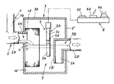
具体的には、機械室1は、図1に図示したように機器としての蒸気ボイラー8と該蒸気ボイラー8に油を供給する給油タンク9とを収納する既存の建物(蒸気ボイラー室)である。符号4はボイラー8と給油タンク9とをつなぐ給油ホースである。
Specifically, machine room 1, in existing buildings for housing the
また、機械室1は床部1aが僅かに傾斜状に設けられており、この床部1aの傾斜最下位置には排水部2が設けられている。
Also, the machine room 1 floor part 1a is provided slightly inclined,
この排水部2は、図1に図示したように適宜な合成樹脂製の管部材を地中に埋設して構成されており、一端部が機械室1の床部1aに接続され、他端部が下水道(図示省略)に接続されている。尚、管部材は合成樹脂製に限らず、コンクリート製や金属製でも良い。
As shown in FIG. 1, the
また、排水部2には雨水供給部7が設けられている。
Further, the
この雨水供給部7は、図1に図示したように機械室1の屋根1bに設けられる軒樋7aと、この軒樋7aに接続され雨水を排水する竪樋7bとから成る既存の雨樋構造であり、この竪樋7bの下端部を、排水部2の所定位置にして該排水部2が後述する油分離部3に接続される位置よりも上流側の位置に接続している。
As shown in FIG. 1, the
従って、雨水供給部7から供給される雨水は排水部2を通過して油分離部3へ供給されることになり、このことは油分離部3の水位を一定に保つことに貢献し、また、雨水供給部7における雨水を集める部分として機械室1の屋根1bにしたのは、可及的に油分などの不純物が入らなくて良く、経済的だからである。
Accordingly, the rainwater supplied from the
尚、本実施例では雨水供給部7に係る竪樋7bを排水部2に接続しているが、油分離部3に接続するようにしても良い。
In the present embodiment, the
また、本実施例では、前述したように対象をボイラー室1としているが、このボイラー室1内に設置されるボイラー8(蒸気ボイラー)からは、その機能上、連続的若しくは間欠的に排水が行われる。 In the present embodiment, the target is the boiler chamber 1 as described above. However, the boiler 8 (steam boiler) installed in the boiler chamber 1 discharges water continuously or intermittently due to its function. Done.
具体的には、この蒸気ボイラーは、ボイラー8内の水質を維持するためのブロー処置(蒸発量の約10%の水を排水する処理)に際して排水作業が連続的若しくは間欠的に行われる。また、この蒸気ボイラーには該蒸気ボイラーに供給する水を軟化(Ca,Mgを除去)する軟水化装置が具備せしめられており、この軟水化装置の性能を維持する処理(イオン交換樹脂の洗浄)に際しても排水が行われる。
Specifically, in this steam boiler, the draining operation is performed continuously or intermittently during the blowing process (a process of draining water of about 10% of the evaporation amount) for maintaining the water quality in the
従って、このボイラー8及びボイラー8に接続される軟水化装置からは、連続的若しくは間欠的に排水が行われ、これら排水が排水部2を流れることで油分離部3の水位は常に一定に保つ作用を発揮することになり、しかも、この排水はボイラー室1内の床部1aに落ちた検知対象となる油Xを排水部2へ流す作用も発揮することになり、極めて効率の良い構造と言える。
Accordingly, drainage is continuously or intermittently performed from the
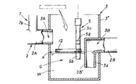
油分離部3は、導入部3Aと導出部3Bを具備する排水収納部3’に、該導入部3Aと該導出部3Bとの間の領域を仕切り壁3aで仕切ることで比重差分離領域Sを設けた構造である。
The
具体的には、排水収納部3’は、図2に図示したように地中に埋設される樹脂製のケース体であり、この排水収納部3’の対向する壁面にして異なる高さ位置には貫通孔が設けられ、この各貫通孔は、前述した排水部2を構成する管部材(上流側管部材2A,下流側管部材2B)が接続される導入部3Aと導出部3Bとして構成されている。
Specifically, the
また、導出部3Bに接続される下流側管部材2Bは、排水収納部3’内で下方に向けて屈曲形成されており、この下流側管部材2Bの先端開口部は上流側管部材2Aの先端開口部よりも低い位置に配され、該下流側管部材2Bの先端部は比重差分離領域Sを形成する仕切り壁3aとして機能する。
Further, the downstream
従って、導入部3Aから導入された水Wは排水収納部3’の下方で開口する下流側管部材2Bの先端開口部を通過して導出部3Bから導出される構成であり、つまり、排水収納部3’には比重差分離領域Sが設けられ比重の重い水Wのみが導出部3Bから導出されることになる。符号3bは開閉蓋、10はフィルターである。
Accordingly, the water W introduced from the
また、油分離部3としては、図4に図示したように排水部2(この場合、例えばU字溝)の途中において、底板2aより立ち上がり、水溜め部を形成する複数の第一板11Aと、この第一板11A間に配され底板2aとの間に流通部14が形成され、上縁が前記第一板11Aの上縁より上方に位置する第二板11Bとを並設した構成としても良く、この場合には、第二板11Bが前述した比重差分離領域Sを形成する仕切り壁として機能し、よって、水Wのみが前記流通部14を通過して排水部2(下流側管部材2B)を流れる。
Further, as shown in FIG. 4, the
また、油分離部3の比重差分離領域Sには油検知部5が設けられている。
An
本実施例では、油検知部5として定水位型の静電容量式センサーが採用されている。
In the present embodiment, a constant water level type capacitive sensor is employed as the
この静電容量式センサー5は、物質によって異なる誘電率の違いを利用して物質の検知を行えるものであり、図2に図示したように電極棒体5Aの途中位置に配される絶縁部5aを境界として先端側電極部5b(測定電極)と基端側電極部5c(アース電極)とを具備した周知構造である。
The
この定水位型の静電容量式センサーは、図5に図示した式で示す原理であり、液面(S/L)を一定にし、εS(センサー接触部の比誘電率)の変化を利用することで水Wと油Xの差を検知するものである。この意味において本実施例の水位を一定に保つ構造に最適である。 This constant water level type capacitive sensor is based on the principle shown in FIG. 5 and uses the change in ε S (dielectric constant of the sensor contact portion) while keeping the liquid level (S / L) constant. By doing so, the difference between the water W and the oil X is detected. In this sense, this embodiment is optimal for the structure that keeps the water level constant.
本実施例では、この静電容量式センサー5に係る電極棒体5Aが排水収納部3’の上方位置に適宜な手段(図示省略)を介して垂設されており、先端側電極部5bが油分離部3(比重差分離領域S)内の水中に配されるように構成されている。
In the present embodiment, the
即ち、電極棒体5Aの先端側電極部5bが水Wに浸けられた状態を正常であるという条件に設定されており、この先端側電極部5bにおいて、基端側電極部5aとの間で予め設定した誘電率の違う物質(水Wと異なる油X)に触れると異常と検知し、その情報(水Wに油Xが混ざっていることの異常)を報知部6に発信することになる。
That is, the condition that the tip
また、本実施例では、静電容量式センサー5に係る電極棒体5Aの表面に適宜な部材(例えばフッ素樹脂やポリウレタン樹脂)でコーティングを施すなどして防爆処理を行っている。
Further, in this embodiment, the explosion-proof treatment is performed by coating the surface of the
従って、電気を流して検知する装置における万一の油の発火等を防止することができる。 Therefore, it is possible to prevent oil from being ignited or the like in an apparatus that detects by flowing electricity.
また、本実施例では、静電容量式センサー5の作動にAC(交流)を利用している。
In this embodiment, AC (alternating current) is used for the operation of the
これは、DC(直流)を利用することで生じる、センサーが電気分解により電極になってしまい腐食するのを防止するためである。 This is to prevent the sensor from becoming an electrode due to electrolysis and corroding, which is caused by using DC (direct current).
報知部6は、図2に図示したように油検知部5に接続され、油検知部5から発信される信号を受信して音を鳴らす警告音部6aと、発光する警告灯6bが設けられている。
As shown in FIG. 2, the
符号6cは報知部6の制御を操作する操作部である。
Reference numeral 6 c denotes an operation unit that operates the control of the
以上の構成から成る本実施例に係る油漏れ検知装置の作動について説明する。 The operation of the oil leakage detection apparatus according to this embodiment having the above-described configuration will be described.
例えばボイラー室1内のボイラー8から油Xが漏れた場合、この油Xはボイラー室1の床部1aに落ち、該床部1aを流れる水Wに流され排水部2に流れる。尚、この床部1aを流れる水Wは、前述したようにボイラー室1内の床部1aを洗い流した水や、貯水タンクからの漏水、貯水タンク内の定期的な水交換の為の排水であるが、油漏れ検査を目的として意図的に流した水でも良い。
For example, when the oil X leaks from the
この排水部2を流れる水Wは油分離部3で全て回収され、比重差分離領域Sにてこの回収された水Wから該水Wに混入した油Xが分離され、当該油分離部3からは排水部2の下流側管部材2Bの先端開口部を通過した水Wのみが排出される。
All of the water W flowing through the
この油分離部3で水Wから分離された油Xは、油検知部5(静電容量式センサー)で検知される。この際、油Xは例えば層状となって水面に浮いて広がり確実に静電容量式センサー5の先端側電極部5bに触れることになり、異常が検知されることになる。
The oil X separated from the water W by the
この油検知部5で油Xを検知すると、この油Xを検知した情報が報知部6へ送られ報知される。
When the oil X is detected by the
その後、油漏れを目視等で確認し、油吸着材12などを用いて油分離部3内の油Xを回収する(図3参照)。
Thereafter, oil leakage is visually confirmed, and the oil X in the
よって、本実施例によれば、前述した従来例と異なり、漏れた油が少量であっても確実に検知することができ、ひいては、油漏れの早期の段階で対応できることになる為、漏れた油によって起きる火災や、河川や海への油流出を防止し得ることになり、しかも、簡易構造であるから既存の機械室1の排水部2に簡易且つコスト安に設置することができる。
Therefore, according to the present embodiment, unlike the above-described conventional example, it is possible to reliably detect even a small amount of leaked oil, and as a result, it is possible to respond at an early stage of the oil leak. Fires caused by oil and oil spills into rivers and seas can be prevented. Moreover, since the structure is simple, it can be installed in the
また、本実施例は、油検知部5として静電容量式センサーを採用したから、油Xの量が少量であっても精度良く確実に検知することができ、しかも、簡易構造である為、コスト安である。この点において、本実施例は既存の機械室1の排水部2に対する施工も極めて簡易且つコスト安に行えることになる。
Moreover, since the present Example employ | adopted the electrostatic capacitance type sensor as the
また、本実施例は、油分離部3は、導入部3Aと導出部3Bを具備する排水収納部3’に、該水導入部4Aと該水導出部4Bとの間の領域を仕切り壁3aで仕切って比重差分離領域Sを設けた構造であり、この比重差分離領域Sに前記油検知部5を配したから、水Wと油Xを良好に分離することができ、油Xの量が少量であっても確実に検知することができる。
Further, in this embodiment, the
また、本実施例は、比重差分離領域Sの水の表面に浮く油を検知するように油検知部5は構成されているから、水Wと油Xの比重差を利用した簡易且つ確実な分離手段のメリット(油Xは水Wに浮くこと)を有効利用して、油Xを下流側に流出させてしまうことなく早期の段階で確実に検知することができる。
Moreover, since the
また、本実施例は、排水部2,油分離部3の少なくとも一方に雨水を供給する雨水供給部7を設けたから、機械室1からの排水だけでなく、雨水を供給することで油分離部3内の水Wの水位を検知に適した一定の状態に維持することができ、常に良好な検知が行えることになる。
Moreover, since the rain
図6は、機械室1の屋上1cに油を取り扱う各種機械13(例えば非常用発電機、冷温水発生器、灯油エアコンなど)が設置される場合に、これら各種機械13からの油漏れを検知し得るように構成した場合である。
6,
具体的には、図6に図示したように機械室1の屋上1cの床部1dを流れる水(雨水など)が、前述した雨水供給部7(雨樋構造)を利用して排水部2に流れるように構成されている。
Specifically, as shown in FIG. 6, water (rainwater, etc.) flowing through the floor 1d of the roof 1c of the machine room 1 is transferred to the
従って、万一、屋上1cに設置される各種機械13から油Xが漏れた場合、この油Xは、例えば雨水とともに雨水供給部7を通過して排水部2に流れて油分離部3に回収され、油検知部5で検知される。
Therefore, in the unlikely event that oil X leaks from
尚、本発明は、本実施例に限られるものではなく、各構成要件の具体的構成は適宜設計し得るものである。 Note that the present invention is not limited to this embodiment, and the specific configuration of each component can be designed as appropriate .
W 水
X 油
1 蒸気ボイラー室
1a 傾斜床部
2 排水部
2A 上流側管部材
2B 下流側管部材
2B’ 管部
3 油分離部
3’ 排水収納部
3A 導入部
3B 導出部
3a 仕切り壁
3b 開閉蓋
5 油検知部
6 報知部
7 雨水供給部
W water
X oil 1 steam boiler room
1a
2A upstream pipe member
2B downstream pipe member
2B '
3b Open /
Claims (5)
Priority Applications (1)
| Application Number | Priority Date | Filing Date | Title |
|---|---|---|---|
| JP2009048227A JP5006892B2 (en) | 2009-03-02 | 2009-03-02 | Oil leak detection device |
Applications Claiming Priority (1)
| Application Number | Priority Date | Filing Date | Title |
|---|---|---|---|
| JP2009048227A JP5006892B2 (en) | 2009-03-02 | 2009-03-02 | Oil leak detection device |
Publications (2)
| Publication Number | Publication Date |
|---|---|
| JP2010203853A JP2010203853A (en) | 2010-09-16 |
| JP5006892B2 true JP5006892B2 (en) | 2012-08-22 |
Family
ID=42965487
Family Applications (1)
| Application Number | Title | Priority Date | Filing Date |
|---|---|---|---|
| JP2009048227A Expired - Fee Related JP5006892B2 (en) | 2009-03-02 | 2009-03-02 | Oil leak detection device |
Country Status (1)
| Country | Link |
|---|---|
| JP (1) | JP5006892B2 (en) |
Families Citing this family (2)
| Publication number | Priority date | Publication date | Assignee | Title |
|---|---|---|---|---|
| KR102236483B1 (en) * | 2019-10-29 | 2021-04-06 | 주식회사 미래인더스트리 | Smart Grease Trap |
| JP7436016B2 (en) | 2020-04-01 | 2024-02-21 | 株式会社タカギ | Leak test tools and leak test methods |
Family Cites Families (3)
| Publication number | Priority date | Publication date | Assignee | Title |
|---|---|---|---|---|
| JPS52110694A (en) * | 1976-03-15 | 1977-09-16 | Asahi Giken Kk | Automatic detector for petroleums |
| JPS54127390A (en) * | 1978-03-27 | 1979-10-03 | Japan Gasoline | Leaked oil detector having oil collecting function |
| JPH07234169A (en) * | 1994-02-25 | 1995-09-05 | Takuma Co Ltd | Oil leakage detection system |
-
2009
- 2009-03-02 JP JP2009048227A patent/JP5006892B2/en not_active Expired - Fee Related
Also Published As
| Publication number | Publication date |
|---|---|
| JP2010203853A (en) | 2010-09-16 |
Similar Documents
| Publication | Publication Date | Title |
|---|---|---|
| KR20130117042A (en) | Trap apparatus for condensate water and drain apparatus for condensate water installed on the same | |
| AU1476602A (en) | Separator device | |
| CN108699826A (en) | Water-washing type toilet closet | |
| JP5006892B2 (en) | Oil leak detection device | |
| CN111059649A (en) | Dehumidifier with multifunctional drainage function and drainage method | |
| KR101756520B1 (en) | Flow control apparatus for self-check | |
| EP3064476A1 (en) | Separator for the separation of oil and/or gasoline from contaminated water | |
| JP2008298367A (en) | Drain discharge system, neutralization device, and hot water heating device | |
| JP5508069B2 (en) | Wastewater transfer system | |
| JP4968525B2 (en) | Hot water heater | |
| JP5005398B2 (en) | Combustion equipment | |
| KR100518684B1 (en) | Atomatic Sewage Sampling System in Manhole | |
| JP2017215075A (en) | Storage type water heater | |
| CN204742241U (en) | Waste liquid automatic discharge of protein isolate ware and stock solution bucket anti -overflow system | |
| JP2007253956A (en) | Oil content sensor, oil outflow preventive device, and oil outflow alarming device | |
| JP4711938B2 (en) | Engine power generator with indoor fuel tank | |
| US20140251460A1 (en) | Wastewater Overflow Prevention System | |
| GB2528787A (en) | A condensate disposal system for disposing of condensate from a condensing fuel burning appliance, a condensing fuel burning appliance having a condensate | |
| JP2010221124A (en) | Water-discharge tank and oil detection method | |
| KR101724292B1 (en) | Vacuum Sewage Treatment Plant | |
| KR200335202Y1 (en) | Atomatic Sewage Sampling System in Manhole | |
| CN108692871B (en) | Water detection equipment for detecting sealing performance of vertical pipe water collector | |
| KR200252912Y1 (en) | The laying catch basin with apparatus for separating oil from water | |
| JP2012180113A (en) | Outdoor fuel storage apparatus | |
| US20200216338A1 (en) | Condensate neutralizer alert |
Legal Events
| Date | Code | Title | Description |
|---|---|---|---|
| A977 | Report on retrieval |
Free format text: JAPANESE INTERMEDIATE CODE: A971007 Effective date: 20111014 |
|
| A131 | Notification of reasons for refusal |
Free format text: JAPANESE INTERMEDIATE CODE: A131 Effective date: 20111107 |
|
| A521 | Written amendment |
Free format text: JAPANESE INTERMEDIATE CODE: A523 Effective date: 20120106 |
|
| TRDD | Decision of grant or rejection written | ||
| A01 | Written decision to grant a patent or to grant a registration (utility model) |
Free format text: JAPANESE INTERMEDIATE CODE: A01 Effective date: 20120510 |
|
| A01 | Written decision to grant a patent or to grant a registration (utility model) |
Free format text: JAPANESE INTERMEDIATE CODE: A01 |
|
| A61 | First payment of annual fees (during grant procedure) |
Free format text: JAPANESE INTERMEDIATE CODE: A61 Effective date: 20120525 |
|
| FPAY | Renewal fee payment (event date is renewal date of database) |
Free format text: PAYMENT UNTIL: 20150601 Year of fee payment: 3 |
|
| R150 | Certificate of patent or registration of utility model |
Ref document number: 5006892 Country of ref document: JP Free format text: JAPANESE INTERMEDIATE CODE: R150 Free format text: JAPANESE INTERMEDIATE CODE: R150 |
|
| FPAY | Renewal fee payment (event date is renewal date of database) |
Free format text: PAYMENT UNTIL: 20180601 Year of fee payment: 6 |
|
| R250 | Receipt of annual fees |
Free format text: JAPANESE INTERMEDIATE CODE: R250 |
|
| R250 | Receipt of annual fees |
Free format text: JAPANESE INTERMEDIATE CODE: R250 |
|
| LAPS | Cancellation because of no payment of annual fees |