JP5004991B2 - Intruder identification device - Google Patents
Intruder identification device Download PDFInfo
- Publication number
- JP5004991B2 JP5004991B2 JP2009089899A JP2009089899A JP5004991B2 JP 5004991 B2 JP5004991 B2 JP 5004991B2 JP 2009089899 A JP2009089899 A JP 2009089899A JP 2009089899 A JP2009089899 A JP 2009089899A JP 5004991 B2 JP5004991 B2 JP 5004991B2
- Authority
- JP
- Japan
- Prior art keywords
- intruder
- signal
- pattern
- feature amount
- identification
- Prior art date
- Legal status (The legal status is an assumption and is not a legal conclusion. Google has not performed a legal analysis and makes no representation as to the accuracy of the status listed.)
- Active
Links
Images


Description
本発明は、検知領域内に侵入物が侵入したことを電波を用いて識別する侵入物識別装置に関する。 The present invention relates to an intruder identification apparatus that uses radio waves to identify that an intruder has entered a detection area.
従来、例えば、線路などの検知領域内に侵入した侵入物を検知する様々な装置が採用されている。侵入物としては、車両、侵入者及び動物などが挙げられるが、防犯上、最も重要な侵入物は検知領域内の設備に危害を及ぼす可能性のある侵入者(人間)である。特許文献1に記載されている侵入検知装置は、送信信号を送信アンテナに供給する送信手段と、上記送信アンテナから放射された電波を受信する受信アンテナと、上記受信アンテナにより受信された受信信号の実部成分と虚部成分を復調する復調手段と、上記復調手段により復調された実部成分と虚部成分から為る複素信号を周波数データに変換し、変換した周波数データを構成する正の周波数と負の周波数との差分値が所定の閾値より大きい場合に、侵入物体の存在を認定する検知手段とを備える。これにより、送信アンテナ又は受信アンテナの風による揺れや、降雨等による地面などの反射率の変動に起因する上記複素信号の直線的な変化に起因する誤検知を防止する。
2. Description of the Related Art Conventionally, for example, various devices that detect an intruder that has entered a detection area such as a track have been adopted. Examples of the intruder include a vehicle, an intruder, and an animal. In terms of crime prevention, the most important intruder is an intruder (human) who may harm the equipment in the detection area. An intrusion detection apparatus described in
また、特許文献2に記載されている侵入物検知方法は、検知エリア内の侵入物を、電波を照射する送信手段を用いて検知する侵入物検知方法であって、前記侵入物に対して異なる方向から照射することによって前記侵入物において照射される領域の広さを異ならせるように、前記送信手段から異なる方向へ走査して、または複数の異なる位置に設けた前記送信手段から、電波を検知エリア内に送信する送信ステップと、前記送信ステップにより送信された前記電波の反射波を受信する受信ステップと、前記受信ステップにより受信された前記反射波に基づいて、受信波強度を測定する測定ステップと、前記送信ステップにおいて異なる方向から照射された領域の広さの差異に応じて、前記測定ステップにより測定された前記受信波強度に基づいて、前記侵入物が人体であるか否か判定する人体判定ステップとを含む。 Further, the intruder detection method described in Patent Document 2 is an intruder detection method for detecting an intruder in a detection area using a transmission unit that radiates radio waves, and is different from the intruder. Scanning in different directions from the transmission means or detecting the radio waves from the transmission means provided at a plurality of different positions so that the area irradiated on the intruder differs by irradiating from the direction. A transmitting step for transmitting into the area, a receiving step for receiving the reflected wave of the radio wave transmitted by the transmitting step, and a measuring step for measuring the received wave intensity based on the reflected wave received by the receiving step And based on the received wave intensity measured by the measurement step according to the difference in the size of the area irradiated from different directions in the transmission step. Te, wherein the intruder and a person determining step of determining whether a human body.
しかしながら、特許文献1に係る侵入検知装置及び特許文献2に係る侵入物検知方法によれば、自然現象によって引き起こされる電波変動時にも、侵入者の侵入を知らせる警報を誤って発することがあった。例えば、特許文献1では、風や降雨等に自然環境の変化に起因する上記差分値の変動が上記しきい値よりも大きいときには、誤発報してしまうという課題があった。また、特許文献2では、受信波強度が所定の範囲内である場合には侵入物が人体であると判定するが、人体の侵入による受信波強度の変動の大きさにバラツキがある場合には、上記範囲を比較的広く設定する必要があり誤発報が発生しやすくなるという課題があった。
However, according to the intrusion detection device according to
本発明の目的は以上の問題点を解決し、環境が変化しても、従来技術に比較して正確に侵入物が侵入したことを識別できる侵入物識別装置を提供することにある。 An object of the present invention is to solve the above-described problems and to provide an intruder identification apparatus capable of accurately identifying that an intruder has intruded compared to the prior art even when the environment changes.
本発明に係る侵入物識別装置は、所定の送信信号を発生して送信アンテナを用いて無線送信する送信手段と、上記送信された送信信号を受信アンテナを用いて無線受信し、上記無線受信した受信信号を上記発生された送信信号を用いて直交検波して複素復調信号に復調する受信手段とを備えた侵入物識別装置において、それぞれ所定の期間長を有する複数の解析期間において、上記複素復調信号から、上記各解析期間においても変化しかつ侵入物の侵入時と非侵入時とで異なるように変化する特徴量パターンを抽出する特徴抽出手段と、上記抽出された特徴量パターンに基づいて、侵入物の侵入時を表す参照特徴量パターンと、侵入物の非侵入時を表す参照特徴量パターンとのうちの少なくとも一方を用いて侵入物が侵入したか否かを識別し、当該識別結果を示す識別信号を出力する識別手段とを備えたことを特徴とする。 An intruder identification device according to the present invention generates a predetermined transmission signal and wirelessly transmits it using a transmission antenna, wirelessly receives the transmitted transmission signal using a reception antenna, and receives the wireless reception in the intruder identifying device provided with a received signal and receiving means for quadrature detection to be demodulated into complex demodulated signal using the transmission signal the occurrence, in each of the plurality of analysis periods having a predetermined period length, the complex Based on the extracted feature quantity pattern, a feature extraction means for extracting a feature quantity pattern that changes in the analysis period and changes in a different manner between the intruder and the non-intruder from the demodulated signal. And whether or not the intruder has intruded is identified using at least one of a reference feature amount pattern that indicates when the intruder has entered and a reference feature amount pattern that indicates when the intruder has not entered. Characterized in that a discrimination means for outputting an identification signal indicating the identification result.
上記侵入物識別装置において、上記特徴量パターンは、上記各解析期間において上記複素復調信号が複素平面上で離散的に変化するときの軌跡を表す複数のベクトルの、大きさ及び方向の少なくとも一方の変化の時系列パターンを含むことを特徴とする。 In the intruder identification apparatus, the feature amount pattern may include at least one of a size and a direction of a plurality of vectors representing a locus when the complex demodulated signal changes discretely on a complex plane in each analysis period. It includes a time series pattern of change.
また、上記侵入物識別装置において、上記特徴量パターンは、上記各解析期間における複素復調信号の周波数スペクトルのパターンを含むことを特徴とする。 In the intruder identification apparatus, the feature amount pattern includes a frequency spectrum pattern of a complex demodulated signal in each analysis period.
さらに、上記侵入物識別装置において、上記特徴抽出手段は、上記各解析期間において、上記複素復調信号を上記周波数スペクトルにフーリエ変換又はウェーブレット変換することを特徴とする。 Further, in the intruder identification apparatus, the feature extraction means performs Fourier transform or wavelet transform on the complex demodulated signal into the frequency spectrum in each analysis period.
またさらに、上記侵入物識別装置において、上記特徴量パターンは、上記各解析期間における上記複素復調信号の共分散行列の分散の変化、もしくは固有値の変化の時系列パターンを含むことを特徴とする。 Still further, in the intruder identification apparatus, the feature amount pattern includes a time series pattern of a change in covariance matrix or a change in eigenvalue of the complex demodulated signal in each analysis period.
また、上記侵入物識別装置において、上記特徴量パターンは、上記各解析期間において上記複素復調信号が複素平面上で離散的に変化するときの軌跡の長さの変化、もしくは当該軌跡によって囲まれる領域の面積の変化の時系列パターンを含むことを特徴とする。 In the intruder identification device, the feature amount pattern may be a change in the length of a locus when the complex demodulated signal changes discretely on a complex plane in each analysis period, or a region surrounded by the locus. It includes a time-series pattern of changes in the area of.
さらに、上記侵入物識別装置において、上記送信アンテナ及び受信アンテナはそれぞれ、アレーアンテナにてなることを特徴とする。 Further, in the intruder identifying apparatus, the transmitting antenna and the receiving antenna are each an array antenna.
またさらに、上記侵入物識別装置において、上記各アレーアンテナは漏洩同軸ケーブルにてなることを特徴とする。 Still further, in the intruder identification apparatus, each of the array antennas is a leaky coaxial cable.
また、上記侵入物識別装置において、上記送信手段は、上記発生された送信信号をPN符号信号を用いてスペクトル拡散して送信することを特徴とする。 In the intruder identification apparatus, the transmission means may perform spectrum spread on the generated transmission signal using a PN code signal and transmit the transmission signal.
さらに、上記侵入物識別装置において、上記受信手段は、上記PN符号信号を互いに異なる複数の遅延時間だけ遅延させて複数の遅延PN符号信号を発生し、上記受信信号を上記複数の遅延PN符号信号を用いて逆拡散して複数の逆拡散受信信号を発生し、上記複数の逆拡散信号をそれぞれ、上記発生された送信信号を用いて直交検波して複素復調信号に復調して出力し、上記侵入物識別装置は、上記複数の遅延時間に対応してそれぞれ設けられた複数の上記特徴抽出手段と、上記複数の遅延時間に対応してそれぞれ設けられた複数の上記識別手段と、上記各識別手段からの識別信号に基づいて上記侵入物の位置を決定する位置決定手段とをさらに備えたことを特徴とする。 Further, in the intruder identification device, the receiving means delays the PN code signal by a plurality of different delay times to generate a plurality of delayed PN code signals, and the received signal is converted into the plurality of delayed PN code signals. A plurality of despread received signals by despreading using, and each of the plurality of despread signals is quadrature detected using the generated transmission signal, demodulated into a complex demodulated signal, and output, The intruder identification apparatus includes a plurality of the feature extraction units provided corresponding to the plurality of delay times, a plurality of the identification units provided corresponding to the plurality of delay times, and the identifications, respectively. And a position determining means for determining the position of the intruder based on an identification signal from the means.
本発明に係る侵入物識別装置は、それぞれ所定の期間長を有する複数の解析期間において、複素復調信号から、各解析期間においても変化しかつ侵入物の侵入時と非侵入時とで異なるように変化する特徴量パターンを抽出する特徴抽出手段と、上記抽出された特徴量パターンに基づいて、侵入物の侵入時を表す参照特徴量パターンと、侵入物の非侵入時を表す参照特徴量パターンとのうちの少なくとも一方を用いて侵入物が侵入したか否かを識別し、当該識別結果を示す識別信号を出力する識別手段とを備えたので、侵入物の侵入時の複素復調信号に特有の特徴量パターンを抽出して、従来技術に比較して侵入物が侵入したことを正確に識別できる。 The intruder identification device according to the present invention changes in each analysis period from a complex demodulated signal in a plurality of analysis periods each having a predetermined period length, and is different between an intruder entry time and a non-intrusion time. A feature extracting means for extracting a changing feature amount pattern, a reference feature amount pattern representing the time of intrusion of the intruder based on the extracted feature amount pattern, and a reference feature amount pattern representing the time of intrusion of the intruder And identifying means for identifying whether or not the intruder has entered using at least one of them, and outputting an identification signal indicating the identification result. By extracting the feature amount pattern, it is possible to accurately identify that the intruder has intruded as compared with the prior art.
以下、本発明に係る実施形態について図面を参照して説明する。なお、以下の各実施形態において、同様の構成要素については同一の符号を付している。 Hereinafter, embodiments according to the present invention will be described with reference to the drawings. In addition, in each following embodiment, the same code | symbol is attached | subjected about the same component.
実施の形態1.
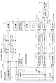
図1は、本発明の実施の形態1に係る侵入物識別装置1の構成を示すブロック図であり、図2は、図1の特徴抽出器16の構成を示すブロック図である。また、図3は、図1の直交検波器14からの複素復調信号の複素平面上でのベクトル軌跡Ocを示すグラフであり、図4(a)は図2の特徴量パターン算出器35によって設定される観測期間To及び解析期間Ta1〜TaNを示すタイミングチャートであり、図4(b)は図2の特徴量パターン算出器35によって算出される特徴量パターンFmax,Fminを示すグラフである。
FIG. 1 is a block diagram showing the configuration of the
図1において、侵入物識別装置1は、信号発生器11を備えた無線送信回路10と、送信アンテナ12と、受信アンテナ13と、直交検波器14を備えた無線受信回路9と、メモリ15,20と、特徴抽出器16と、識別器17と、学習サンプルデータメモリ18と、学習器19と、識別結果出力器21とを備えて構成される。また、図2において、特徴抽出器16は、差分ベクトル算出器31と、変化量算出器33と、特徴量パターン算出器35と、メモリ32,34とを備えて構成される。ここで、差分ベクトル算出器31、変化量算出器33、特徴量パターン算出器35、学習器19及び識別器17は、具体的にはCPU又はディジタル・シグナル・プロセッサ(以下、DSPという。)によって構成される。また、侵入物識別装置1は、無線送信回路10及び無線受信回路9が送信アンテナ12及び受信アンテナ13を用いて互いに無線通信可能な領域である検知領域を有する。
In FIG. 1, the
詳細後述するように、本実施形態に係る侵入物識別装置1は、所定の送信信号を発生して送信アンテナ12を用いて無線送信する無線送信回路10と、上記送信された送信信号を受信アンテナ13を用いて無線受信し、上記無線受信した送信信号を上記発生された送信信号を用いて直交検波して複素復調信号に復調する無線受信回路9とを備えた侵入物識別装置1において、それぞれ所定の期間長ΔTを有する複数の解析期間Ta1〜TaNにおいて、上記複素復調信号から、上記各解析期間においても変化しかつ侵入者の侵入時と非侵入時とで異なるように変化する特徴量パターンFmax,Fminを抽出する特徴抽出器16と、上記抽出された特徴量パターンFmax,Fminに基づいて、侵入物の侵入時を表す参照特徴量パターンと、侵入者の非侵入時を表す参照特徴量パターンと用いて侵入者が侵入したか否かを識別し、当該識別結果を示す識別信号S17を出力する識別器17とを備えたことを特徴としている。
As will be described in detail later, the
図1において、無線送信回路10は、信号発生器11によって発生された所定の送信信号を送信アンテナ12に出力して電波として放射するとともに、上記送信信号を直交検波器14に出力する。送信アンテナ12によって放射された電波は受信アンテナ13によって受信信号として受信される。直交検波器14は、信号発生器11からの送信信号を用いて、上記受信信号を複素復調信号の実部である同相成分及び虚部である直交成分に直交検波してメモリ15に出力する。
In FIG. 1, a
図2において、差分ベクトル算出器31は、始めに、メモリ15に記憶された複素復調信号の同相成分及び直交成分をそれぞれ1/16秒周期でサンプリングして離散化する。図3に、サンプリングタイミングt1,t2,t3,t4でそれぞれサンプリングされた複素復調信号Sc1,Sc2,Sc3,Sc4の一例を、複素平面上にプロットして示す。図3に示すように、複素復調信号は複素平面上でベクトル軌跡Ocを描く。次に、差分ベクトル算出器31は、各連続する2つのサンプリングタイミングにおける複素復調信号Sc1,Sc2,…の同相成分の差及び直交成分の差を算出することにより、複素復調信号の複素平面上でのベクトル軌跡Ocを表す差分ベクトルV12,V23,V34,…を算出してメモリ32に出力する。例えば、図3において、差分ベクトルV12の同相成分はタイミングt2における複素復調信号Sc2の同相成分I2からタイミングt2における複素復調信号Sc1の同相成分I1を減算することによって算出され、差分ベクトルV12の直交成分はタイミングt2における複素復調信号Sc2の直交成分Q2からタイミングt2における複素復調信号Sc1の直交成分Q1を減算することによって算出される。
In FIG. 2, the
図2において、変化量算出器33は、メモリ32に記憶された差分ベクトルV12,V23,V34,…に基づいて、各連続する2つの差分ベクトルがなす角度を算出する。例えば、図3において、ベクトルV12とベクトルV23とがなす角度θ12が算出され、ベクトルV23とベクトルV34とがなす角度θ23が算出される。そして、変化量算出器33は、算出された各角度θ12,θ23,…の余弦cosθ12,cosθ23,…(以下、cosθの時系列パターンという。)を算出してメモリ34に出力する。
2, the
次に、特徴量パターン算出器35は、図4(a)に示すように、所定の長さの期間長を有する観測期間Toを設定し、観測期間To内に期間長ΔTをそれぞれ有する複数N個の解析期間Ta1,Ta2,…,TaNを設ける。ここで、観測期間Toの長さは、侵入物識別装置1の検知領域内を侵入者が通過するために必要とされる時間期間(例えば、1秒〜2秒である。)よりも十分長い値に設定され、例えば、5秒〜10秒の範囲内の値を有する。また、各解析期間Ta1,Ta2,…,TaNの長さΔTは、侵入物識別装置1の検知領域内を侵入者が通過するために必要とされる時間期間以下の値に設定され、例えば、2秒である。さらに、隣り合う解析期間Ta1,Ta2,…,TaNは互いに一部が重なるように設けられる。
Next, as shown in FIG. 4A, the feature
さらに、特徴量パターン算出器35は、図4(b)に示すように、メモリ34に記憶されたcosθの時系列パターンに基づいて、各解析期間Ta1,Ta2,…,TaNにおけるcosθの時系列パターンを1つのグラフにプロットする。そして、最大の値を有する解析期間のcosθの時系列パターンと、最小の値を有するcosθの時系列パターンとを、特徴量パターンFmax,Fminとしてそれぞれ識別器17に出力する。
Further, as shown in FIG. 4B, the feature
ここで、送信アンテナ12から放射された電波が侵入者に当たると上記電波は散乱されるので、複素復調信号のベクトル軌跡Ocは、侵入者が存在しないときの点を中心に円を描いて滑らかに変化するという特徴を有する。一方、送信アンテナ12及び受信アンテナ13が揺れたときや、降雨等による地面などの反射率の変動が生じたときには、複素復調信号のベクトル軌跡Ocは細い楕円か直線の形状で振動するという特徴を有する。さらに、侵入者の侵入時の複素復調信号のベクトル軌跡Ocの変化は、自然現象に起因する変化に比較して、短時間であるという特徴を有する。このため、図4(a)に示すように、侵入物識別装置1の検知領域内を侵入者が通過するために必要とされる時間期間よりも十分長い観測期間Toを設け、侵入物識別装置1の検知領域内を侵入者が通過するために必要とされる時間期間以下の期間長ΔTを有する解析期間Ta1〜TaNを設けることにより、侵入者が侵入した期間T2を含む解析期間Taと、侵入者が侵入していない期間T1又はT3のみを含む解析期間Taとを得ることができる。さらに、侵入者が侵入した期間T2を含む解析期間Taにおけるベクトル軌跡Ocのcosθの時系列パターンは、侵入者が侵入していない期間T1又はT3を含む解析期間Taにおけるベクトル軌跡Ocのcosθの時系列パターンに比較して大きい値を有する。このため、図4(a)に示すように、観測期間To内に侵入者が侵入した場合は、特徴量パターン算出器35によって算出される特徴量パターンFmaxは、侵入者が侵入した期間T2の複素復調信号のベクトル軌跡Ocの特徴を表し、特徴量パターンFminは侵入者が侵入していない期間T1又はT3の複素復調信号のベクトル軌跡Ocの特徴を表す。
Here, when the radio wave radiated from the transmitting
図1において、学習サンプルデータメモリ18は、侵入者の侵入時か非侵入時かを識別する識別ラベルをそれぞれ有する、特徴量パターンFmax,Fminの複数の学習特徴量パターンを予め記憶している。学習器19は、学習特徴量パターンメモリ18からの学習特徴量パターン及び侵入者の侵入時及び非侵入時の特徴量抽出器16からの特徴量パターンFmax,Fminの実測値を用いて学習を行い、侵入者の侵入時及び非侵入時の特徴量パターンFmax,Fminの代表的なパターンを作成し、侵入物の侵入時を表わす参照特徴量パターン及び侵入物の非侵入時を表わす参照特徴量パターンとしてメモリ20に出力する。識別器17は、特徴量抽出器16からの特徴量パターンFmax,Fminに基づいて、メモリ20に記憶された侵入物の侵入時を表わす参照特徴量パターン及び侵入物の非侵入時を表わす参照特徴量パターン、特徴量抽出器16を用いてパターン認識処理を行い、特徴量パターンFmaxが侵入者の侵入を表わすか否かを識別し、当該識別結果を示す識別信号S17を発生して識別結果出力器21に出力する。識別結果出力器21はスピーカ及びディスプレイ装置であって、侵入者の侵入を示す識別信号S17に応答して、スピーカから所定の警報音を出力し、かつディスプレイ装置上に所定の警告表示を行う。
In FIG. 1, a learning
従って、本実施形態に係る侵入物識別装置1によれば、連続する2つの差分ベクトルの間の角度θを用いて特徴量パターンFmax,Fminを算出するので、特徴量パターンFmaxによって、検知領域に侵入者が侵入したときに複素復調信号のベクトル軌跡Ocが滑らかに変化するという特徴を抽出することができる。
Therefore, according to the
また、侵入物識別装置1の検知領域内を侵入者が通過するために必要とされる時間期間よりも十分長い観測期間Toを設け、侵入物識別装置1の検知領域内を侵入者が通過するために必要とされる時間期間以下の期間長ΔTを有する解析期間Ta1〜TaNを設けることにより、侵入者が侵入した期間T2を含む解析期間Taの特徴量パターンFmaxと、侵入者が侵入していない期間T1又はT3のみを含む解析期間Taの特徴量パターンFminとを得ることができる。そして、識別器17は特徴量パターンFmax,Fminに基づいてパターン認識処理を行うので、侵入者の侵入を雨や風による自然現象に起因する複素復調信号の変動と区別して、従来技術に比較して高い精度で識別できる。また、侵入者の侵入による複素復調信号の変化が自然現象に起因する複素復調信号の変化に比較して比較的短時間に集中するという特徴を抽出することができる。
In addition, an observation period To that is sufficiently longer than the time period required for the intruder to pass through the detection area of the
さらに、識別結果出力器21によって侵入者の侵入をディスプレイ装置上に表示し、音で知らせるように構成したので、監視作業員の監視作業を容易にすることができる。
Further, since the intruder intrusion is displayed on the display device by the identification
なお、上記実施形態において、特徴量パターン算出器35は、各解析期間において、連続する2つの差分ベクトル間の角度θの余弦(cosθ)の時系列パターンを特徴量パターンとして抽出した。しかしながら、本発明はこれに限られず、特徴量パターンは、各解析期間において複素復調信号が複素平面上で離散的に変化するときの軌跡Ocを表す複数の差分ベクトルの、大きさ及び方向の少なくとも一方の変化の時系列パターンを含めばよい。具体的には、上記特徴量パターンは、連続する又は所定の時間間隔だけ離れた2つの差分ベクトル間の角度と、上記2つの差分ベクトルのうちの少なくとも一方の差分ベクトルの大きさと、上記角度の三角関数と、上記角度の三角関数の絶対値とのうちの少なくとも1つに基づいて算出される所定の値の時系列パターンであってもよい。例えば、上記所定の値は、連続する2つの差分ベクトルがなす角度、上記角度の三角関数の値、上記角度の三角関数の値の絶対値、上記角度といずれか一方の差分ベクトルの大きさに基づいて算出される値、上記角度の余弦といずれか一方の差分ベクトルの大きさとの積の値、及び差分ベクトルの大きさのうちのいずれか1つであってもよい。これにより、侵入者の侵入時の複素復調信号のベクトル軌跡Ocの特徴である滑らかな変化を表す特徴量パターンFmax,Fminを抽出でき、比較的少ない演算量で特徴量パターンFmax,Fminを算出できる。
In the above embodiment, the feature
実施の形態2.
図5は、本発明の実施の形態2に係る侵入物識別装置1Aの構成を示すブロック図である。侵入物識別装置1Aは、信号発生器11及び乗算器41を備えた無線送信回路10Aと、送信アレーアンテナ43と、受信アレーアンテナ46と、終端器44,45と、PN符号発生器42と、無線受信回路9Aと、複数M個のメモリ15−1〜15−Mと、複数M個の特徴抽出器16−1〜16−Mと、複数M個の識別器17−1〜17−Mと、学習特徴量パターンメモリ18と、学習器19と、メモリ20と、位置決定器22と、識別結果出力器21とを備えて構成される。ここで、送信アレーアンテナ43は複数L個の送信アンテナ43−1〜43−Lとしてそれぞれ機能する複数L個のスリットを有しかつ線状に配置された漏洩同軸ケーブル(LCX(Leaky Coaxial Cable))にてなる。また、受信アレーアンテナは、複数L個の受信アンテナ46−1〜46−Lとしてそれぞれ機能する複数L個のスリットを有しかつ線状に配置された漏洩同軸ケーブルにてなる。さらに、無線受信回路9Aは、遅延器47と、複数M個の乗算器48−1〜48−Mと、複数M個の直交検波器14−1〜14−Mとを備えて構成される。
Embodiment 2. FIG.
FIG. 5 is a block diagram showing a configuration of an intruder identification apparatus 1A according to Embodiment 2 of the present invention. The intruder identification device 1A includes a
詳細後述するように、本実施形態に係る侵入物識別装置1Aは、漏洩同軸ケーブルにて成る送信アレーアンテナ43及び受信アレーアンテナ46を備え、無線送信回路10Aにおいて送信信号をPN符号信号を用いてスペクトル拡散して送信し、無線通信回路9Aにおいて、上記PN符号信号を互いに異なる複数の遅延時間ΔD1〜ΔDMだけ遅延させて複数の遅延PN符号信号を発生し、受信信号を上記複数の遅延PN符号信号を用いて逆拡散して複数の逆拡散受信信号を発生し、上記複数の各逆拡散信号をそれぞれ複素復調信号に復調して出力したことを特徴としている。また、複数の遅延時間ΔD1〜ΔDMに対応して設けられた識別器17−1〜17−Mからの識別信号S17−1〜S17−Mに基づいて侵入者の位置を決定する位置決定器22をさらに備えたことを特徴としている。
As will be described in detail later, the intruder identification device 1A according to the present embodiment includes a
PN符号発生器42は、PN符号信号を発生して乗算器41及び遅延器47に出力する。無線送信回路10は、信号発生器11によって発生された所定の送信信号にPN符号信号を乗算することにより、送信信号をスペクトル拡散して送信アレーアンテナ43を用いて電波として放射するとともに、上記送信信号を直交検波器14−1〜14−Mに出力する。送信アレーアンテナ43によって放射された電波は受信アレーアンテナ46によって受信信号として受信され、乗算器48−1〜48−Mに出力される。ここで、終端器44は、送信アレーアンテナ43によって放射されずに残った電波を吸収し、終端器45は受信アレーアンテナ46によって受信された電波のうち、乗算器48−1〜48−Mと反対側に進行する電波を吸収する。
The
受信信号は、送信アレーアンテナ43と受信アレーアンテナ46との間の互いに異なる複数の伝搬経路に依存して様々な遅延時間を持って受信される。このことを考慮し、遅延器47は、PN符号発生器42によって発生されたPN符号信号を、互いに異なる複数M個の遅延量ΔD1〜ΔDMだけ遅延させて、各遅延された遅延PN符号信号を乗算器48−1〜48−Mにそれぞれ出力する。乗算器48−1〜48−Mはそれぞれ、入力される受信信号に入力される遅延PN符号信号を乗算することにより受信信号を逆拡散して逆拡散受信信号を発生し、直交検波器14−1〜14−Mに出力する。
The received signal is received with various delay times depending on a plurality of mutually different propagation paths between the transmitting
直交検波器14−1〜14−M、メモリ15−1〜15−M、特徴抽出器16−1〜16−M及び識別器17−1〜17−Mはそれぞれ、実施の形態1に係る直交検波器14、メモリ15、特徴抽出器16及び識別器17と同様に構成されるので、その動作の説明を省略する。識別器17−1〜17−Mはそれぞれ、識別器17と同様に、入力される特徴量パターンFmaxが侵入者の侵入を示すか否かを識別し、当該識別結果を示す識別信号S17−1〜S17−Mを発生して位置決定器22に出力する。位置決定器22はCPU又はDSPにてなり、識別信号S17−1〜S17−Mのうち侵入者の侵入を示す識別信号S17−mに対応する遅延量ΔDmに基づいて、侵入者の位置(例えば、受信アレーアンテナ46の左端から侵入者までの距離である。)を決定し、当該決定結果及び侵入者の侵入を示す信号を識別結果出力器21に出力する。これに応答して、識別結果出力器21は、スピーカから所定の警報音を出力し、かつディスプレイ装置上に侵入者の位置を示す警告表示を行う。
The orthogonal detectors 14-1 to 14-M, the memories 15-1 to 15-M, the feature extractors 16-1 to 16-M, and the discriminators 17-1 to 17-M are respectively orthogonal according to the first embodiment. Since the
本実施形態によれば、実施の形態1に比較して、送信アレーアンテナ43及び受信アレーアンテナ46を用いたので、侵入物識別装置1Aの検知領域を広げることができる。特に、送信アレーアンテナ43及び受信アレーアンテナ46を漏洩同軸ケーブルを用いて実現したので、当該漏洩同軸ケーブルの長手方向に一様に上記検知領域を広げることができる。さらに、互いに異なる遅延時間ΔD1〜ΔDMにそれぞれ対応する複素復調信号を発生し、遅延時間ΔD1〜ΔDMにそれぞれ対応する複素復調信号毎にベクトル軌跡Ocの変化の特徴を抽出し、侵入者の侵入を識別するので、実施の形態1に比較して識別精度を向上し侵入者の位置を特定できる。またさらに、PN符号を用いて送信信号をスペクトル拡散させるので、実施の形態1に比較して妨害波や干渉波への耐性を向上できる。
According to the present embodiment, since the
実施の形態3.
図6は、本発明の実施の形態3に係る特徴抽出器16Aの構成を示すブロック図である。特徴抽出器16Aは、周波数変換器51と、メモリ52と、特徴量パターン算出器35Aとを備えて構成される。本実施形態に係る特徴抽出器16Aは、特徴量パターン算出器35Aにおいて、各解析期間Ta1〜TaNにおける複素復調信号の周波数スペクトルのパターンを抽出したことを特徴としている。
Embodiment 3 FIG.
FIG. 6 is a block diagram showing a configuration of a feature extractor 16A according to Embodiment 3 of the present invention. The feature extractor 16A includes a
図6において、周波数変換器51及び特徴量パターン算出器35Aは、具体的にはCPU又はDSPによって構成される。周波数変換器51は、実施の形態1における特徴量パターン算出器35と同様に、所定の長さの期間長を有する観測期間Toを設定し、観測期間To内に期間長ΔTをそれぞれ有する複数N個の解析期間Ta1,Ta2,…,TaNを設ける(図4(a)参照。)。そして、各解析期間Ta1〜TaN毎に、メモリ15に記憶された複素復調信号を周波数スペクトルZ(f)(fは周波数である。)にフーリエ変換してメモリ52に出力する。さらに、特徴量パターン算出器35Aは、メモリ52に記憶された各解析期間Ta1〜TaNにおける周波数スペクトルZ(f)を1つのグラフにプロットする。そして、最大の周波数スペクトルZ(f)を有する解析期間の周波数スペクトルZ(f)のパターンと、最小の周波数スペクトルZ(f)を有する解析期間の周波数スペクトルZ(f)のパターンとを、特徴量パターンFmax,Fminとして識別器17に出力する。
In FIG. 6, the
一般に、侵入者の侵入時の複素復調信号は、送信アンテナ12及び受信アンテナ13の揺れや、降雨等による地面などの反射率の変動などの自然現象の変動時の複素復調信号に比較して低周波成分を多く含む。このため、図4(a)に示すように、観測期間To内に侵入者が侵入した場合は、特徴量パターン算出器35Aによって算出される特徴量パターンFmaxは、侵入者が侵入した期間T2の複素復調信号の周波数成分の特徴を表し、特徴量パターンFminは侵入者が侵入していない期間T1又はT3の複素復調信号の周波数成分の特徴を表す。
In general, a complex demodulated signal when an intruder invades is lower than a complex demodulated signal when a natural phenomenon such as fluctuations in reflectance of the ground due to shaking of the transmitting
本実施形態は、侵入者の侵入時の複素復調信号の周波数スペクトルを表す特徴量パターンを算出して、侵入者の侵入を検知できるという効果を奏する。 This embodiment has an effect that it is possible to detect an intruder's intrusion by calculating a feature amount pattern representing a frequency spectrum of a complex demodulated signal when the intruder invades.
なお、特徴量パターン算出器35Aにおいて、各解析期間Ta1〜TaNにおける複素復調信号の周波数スペクトルのパターンを抽出したが、本発明はこれに限られず、上記周波数スペクトルのパターンを含む特徴量パターンを抽出すればよい。例えば、特徴量パターン算出器35Aにおいて、周波数スペクトルZ(f)のパターンに代えて、以下の値Za又はZbのパターンを抽出してもよい。
In the feature

値Zaは、各周波数fにおける複素復調信号のベクトル軌跡Ocの回転成分の大きさを表し、値Zbは、複素復調信号の回転に依存しない各周波数成分の大きさを表す。いずれの値も、複素復調信号のベクトル軌跡Ocの回転の向きに依存しないので、学習特徴量パターンのデータ量を少なくすることができる。 The value Za represents the magnitude of the rotation component of the vector locus Oc of the complex demodulated signal at each frequency f, and the value Zb represents the magnitude of each frequency component that does not depend on the rotation of the complex demodulated signal. Since any value does not depend on the direction of rotation of the vector locus Oc of the complex demodulated signal, the data amount of the learning feature amount pattern can be reduced.
また、本実施形態において周波数変換器51は複素復調信号を周波数スペクトルにフーリエ変換したが、本発明はこれに限られず、複素復調信号を周波数スペクトルにウェーブレット変換してもよい。フーリエ変換又はウェーブレット変換を用いることにより、複素復調信号を比較的容易に周波数変換できる。
In the present embodiment, the
実施の形態4.
図7は、本発明の実施の形態4に係る特徴抽出器16Bの構成を示すブロック図である。特徴抽出器16Bは、行列計算器61と、メモリ62と、特徴量パターン算出器35Bとを備えて構成される。本実施形態に係る特徴抽出器16Bは、特徴量パターン算出器35Bにおいて、各解析期間Ta1〜TaNにおける複素復調信号の共分散行列の分散の変化の時系列パターンを抽出したことを特徴としている。
Embodiment 4 FIG.
FIG. 7 is a block diagram showing a configuration of a feature extractor 16B according to Embodiment 4 of the present invention. The feature extractor 16B includes a
図7において、行列計算器61及び特徴量パターン算出器35Bは、具体的にはCPU又はDSPによって構成される。行列計算器61は、解析期間の期間長ΔTより短い所定の期間長を有するサブ観測期間毎に、メモリ15に記憶された複素復調信号の同相成分及び直交成分から共分散行列を算出し、当該共分散行列の分散を算出してメモリ62に出力する。特徴量パターン算出器35Bは、実施の形態1における特徴量パターン算出器35と同様に、所定の長さの期間長を有する観測期間Toを設定し、観測期間To内に期間長ΔTをそれぞれ有する複数N個の解析期間Ta1,Ta2,…,TaNを設ける(図4(a)参照。)。そして、メモリ62に記憶された分散を用いて、各解析期間Ta1〜TaN毎に分散の時系列パターンを1つのグラフにプロットする。そして、最大の分散を有する解析期間の分散の時系列パターンと、最小の分散を有する解析期間の分散の時系列パターンとを、特徴量パターンFmax,Fminとして識別器17に出力する。
In FIG. 7, the
上述したように、侵入者の侵入時の複素復調信号のベクトル軌跡Ocは、円を描いて滑らかに変化するという特徴を有する。このため、侵入者の侵入時の複素復調信号の分散は、非侵入時の複素復調信号の分散よりも大きくなる。従って、図4(a)に示すように、観測期間To内に侵入者が侵入した場合は、特徴量パターン算出器35Aによって算出される特徴量パターンFmaxは、侵入者が侵入した期間T2の複素復調信号のベクトル軌跡Ocの特徴を表し、特徴量パターンFminは侵入者が侵入していない期間T1又はT3の複素復調信号のベクトル軌跡Ocの特徴を表す。
As described above, the vector locus Oc of the complex demodulated signal at the time of intrusion by the intruder has a characteristic of smoothly changing in a circle. For this reason, the variance of the complex demodulated signal at the time of intrusion by the intruder becomes larger than the variance of the complex demodulated signal at the time of non-intrusion. Therefore, as shown in FIG. 4A, when an intruder enters during the observation period To, the feature amount pattern Fmax calculated by the feature
本実施形態は、侵入者の侵入時の複素復調信号のベクトル軌跡Ocを表す特徴量を算出して、侵入者の侵入を検知できるという効果を奏する。 This embodiment has an effect that the feature amount representing the vector locus Oc of the complex demodulated signal at the time of intruder intrusion can be calculated to detect the intruder intrusion.
なお、本実施形態において、特徴量パターン算出器35Bにおいて、各解析期間Ta1〜TaNにおける複素復調信号の共分散行列の分散の変化の時系列パターンを抽出したが、本発明はこれに限られず、上記共分散行列の分散の変化、もしくは固有値の変化の時系列パターンを抽出すればよい。例えば、特徴量パターン算出器35Bにおいて、複素復調信号の共分散行列の固有値の時系列パターンを抽出してもよい。ここで、上記固有値の値が大きい順に第1主成分、第2主成分という。
In the present embodiment, the feature
また、特徴量パターン算出器35Bにおいて、各解析期間Ta1〜TaNにおいて複素復調信号が複素平面上で離散的に変化するときの軌跡の長さの変化、もしくは当該軌跡によって囲まれる領域の面積の変化の時系列パターンを抽出してもよい。例えば、複素復調信号のベクトル軌跡Oc長さ(軌道長)Lo及びベクトル軌跡Ocによって囲まれる領域の面積(軌道面積)Aoはそれぞれ、複素復調信号の同相成分I(i)及びQ(i)(iはサブ解析期間内のサンプリングタイミングである。)を用いて、次式で表される。
Further, in the feature
軌道長Lo及び軌道面積Aoにおいて、サブ解析期間内の全てのサンプリングタイミングiに対して総和を算出する。侵入者の侵入時の複素復調信号の軌道長Lo及び軌道面積Aoは、非侵入時の複素復調信号の軌道長Lo及び軌道面積Aoに比較して大きい値を有するという特徴を有する。 For the trajectory length Lo and the trajectory area Ao, the sum is calculated for all sampling timings i within the sub-analysis period. The trajectory length Lo and trajectory area Ao of the complex demodulated signal at the time of intrusion by the intruder has a characteristic that it has a larger value than the trajectory length Lo and trajectory area Ao of the complex demodulated signal at the time of non-intrusion.
なお、実施の形態2に係る侵入物識別装置1Aにおいて、特徴抽出器16−1〜16−Mに代えて、実施の形態3に係る特徴抽出器16A又は実施の形態4に係る特徴抽出器16Bを用いてもよい。 Note that in the intruder identification device 1A according to the second embodiment, instead of the feature extractors 16-1 to 16-M, the feature extractor 16A according to the third embodiment or the feature extractor 16B according to the fourth embodiment. May be used.
また、上記各実施形態において、特徴抽出器16,16−1〜16−Mによって抽出される特徴量パターンは、(1)各解析期間Ta1〜TaNにおいて複素復調信号が複素平面上で離散的に変化するときの軌跡を表す複数のベクトルの、大きさ及び方向の少なくとも一方の変化の時系列パターンを含む特徴量パターン、(2)各解析期間Ta1〜TaNにおける複素復調信号の周波数スペクトルのパターンを含む特徴量パターン、(3)各解析期間Ta1〜TaNにおける複素復調信号の共分散行列の分散の変化、もしくは固有値の変化の時系列パターンを含む特徴量パターン、又は(4)各解析期間Ta1〜TaNにおいて複素復調信号が複素平面上で離散的に変化するときの軌跡の長さの変化、もしくは当該軌跡によって囲まれる領域の面積の変化の時系列パターンを含む特徴量パターンであった。しかしながら、本発明はこれに限られず、特徴抽出器16,16−1〜16−Mは、各解析期間Ta1〜TaNにおいて、複素復調信号から、各解析期間Ta1〜TaNにおいても変化しかつ侵入物の侵入時と非侵入時とで異なるように変化する特徴量パターンを抽出すればよい。
In each of the above embodiments, the feature quantity patterns extracted by the
さらに、上記各実施形態において、識別器17,17−1〜17−Mは、侵入物の侵入時を表す参照特徴量パターンと侵入者の非侵入時を表す参照特徴量パターンとを用いたが、侵入物の侵入時を表す参照特徴量パターンと侵入者の非侵入時を表す参照特徴量パターンとのうちの少なくとも一方を用いればよい。
Further, in each of the above embodiments, the
またさらに、上記各実施形態において、侵入物識別装置1及び1Aは検知領域内に侵入者が侵入したことを識別したが、本発明はこれに限られず、犬及び猫などの小動物である侵入物が検知領域内に侵入したことを識別してもよい。
Furthermore, in each of the above embodiments, the
以上詳述したように、本発明に係る侵入物識別装置は、それぞれ所定の期間長を有する複数の解析期間において、複素復調信号から、各解析期間においても変化しかつ侵入物の侵入時と非侵入時とで異なるように変化する特徴量パターンを抽出する特徴抽出手段と、上記抽出された特徴量パターンに基づいて、侵入物の侵入時を表す参照特徴量パターンと、侵入物の非侵入時を表す参照特徴量パターンとのうちの少なくとも一方を用いて侵入物が侵入したか否かを識別し、当該識別結果を示す識別信号を出力する識別手段とを備えたので、侵入物の侵入時の複素復調信号に特有の特徴量パターンを抽出して、従来技術に比較して侵入物が侵入したことを正確に識別できる。 As described above in detail, the intruder identification device according to the present invention changes from a complex demodulated signal in each analysis period in a plurality of analysis periods each having a predetermined period length, and is different from that at the time of intrusion intrusion. Feature extraction means for extracting a feature amount pattern that changes differently at the time of intrusion, a reference feature amount pattern that represents the time of intrusion, based on the extracted feature amount pattern, and a time when the intruder is not intruding And an identification means for identifying whether or not the intruder has intruded using at least one of the reference feature amount patterns representing the output and outputting an identification signal indicating the identification result. The characteristic amount pattern peculiar to the complex demodulated signal is extracted, and it is possible to accurately identify that the intruder has intruded as compared with the prior art.
1,1A 侵入物識別装置、9,9A 無線受信回路、10,10A 無線送信回路、11 信号発生器、12 送信アンテナ、13 受信アンテナ、14,14−1〜14−M 直交検波器、15,15−1〜15−M,20,32,52,62 メモリ、16 特徴抽出器、17,17−1〜17−M 識別器、18 学習特徴量パターンメモリ、19 学習器、21 識別結果出力器、22 位置決定器、31 ベクトル算出器、33 変動量算出器、35,35A,35B 特徴量パターン算出器、41,48−1〜48−M 乗算器、42 PN符号発生器、43 送信アレーアンテナ、44,45 終端器、46 受信アレーアンテナ、47 遅延器、51 周波数変換器。
DESCRIPTION OF
Claims (10)
上記送信された送信信号を受信アンテナを用いて無線受信し、上記無線受信した受信信号を上記発生された送信信号を用いて直交検波して複素復調信号に復調する受信手段とを備えた侵入物識別装置において、
それぞれ所定の期間長を有する複数の解析期間において、上記複素復調信号から、上記各解析期間においても変化しかつ侵入物の侵入時と非侵入時とで異なるように変化する特徴量パターンを抽出する特徴抽出手段と、
上記抽出された特徴量パターンに基づいて、侵入物の侵入時を表す参照特徴量パターンと、侵入物の非侵入時を表す参照特徴量パターンとのうちの少なくとも一方を用いて侵入物が侵入したか否かを識別し、当該識別結果を示す識別信号を出力する識別手段とを備えたことを特徴とする侵入物識別装置。 Transmitting means for generating a predetermined transmission signal and wirelessly transmitting using a transmission antenna;
Wirelessly received using the receiving antennas a transmission signal transmitted above, and a receiving means for demodulating the complex demodulated signal received signals the wireless receiver to quadrature detection by using the transmission signal the occurrence intrusion In the object identification device,
In a plurality of analysis periods each having a predetermined period length, feature amount patterns that change also in each analysis period and change differently at the time of intrusion and non-intrusion are extracted from the complex demodulated signal. Feature extraction means;
Based on the extracted feature amount pattern, the intruder has intruded using at least one of the reference feature amount pattern indicating the intruder entry time and the reference feature amount pattern indicating the intruder non-intrusion time. An intruder identification apparatus comprising: an identification unit that identifies whether or not the identification result is output, and outputs an identification signal indicating the identification result.
上記侵入物識別装置は、
上記複数の遅延時間に対応してそれぞれ設けられた複数の上記特徴抽出手段と、
上記複数の遅延時間に対応してそれぞれ設けられた複数の上記識別手段と、
上記各識別手段からの識別信号に基づいて上記侵入物の位置を決定する位置決定手段とをさらに備えたことを特徴とする請求項9記載の侵入物識別装置。 The receiving means delays the PN code signal by a plurality of different delay times to generate a plurality of delayed PN code signals, despreads the received signal using the plurality of delayed PN code signals, Generate a despread received signal, each of the plurality of despread signals is quadrature detected using the generated transmission signal, demodulated into a complex demodulated signal, and output,
The intruder identification device is
A plurality of the feature extraction means respectively provided corresponding to the plurality of delay times;
A plurality of the identifying means respectively provided corresponding to the plurality of delay times;
10. The intruder identification apparatus according to claim 9, further comprising position determining means for determining a position of the intruder based on an identification signal from each identification means.
Priority Applications (1)
| Application Number | Priority Date | Filing Date | Title |
|---|---|---|---|
| JP2009089899A JP5004991B2 (en) | 2009-04-02 | 2009-04-02 | Intruder identification device |
Applications Claiming Priority (1)
| Application Number | Priority Date | Filing Date | Title |
|---|---|---|---|
| JP2009089899A JP5004991B2 (en) | 2009-04-02 | 2009-04-02 | Intruder identification device |
Publications (3)
| Publication Number | Publication Date |
|---|---|
| JP2010243231A JP2010243231A (en) | 2010-10-28 |
| JP2010243231A5 JP2010243231A5 (en) | 2011-03-17 |
| JP5004991B2 true JP5004991B2 (en) | 2012-08-22 |
Family
ID=43096406
Family Applications (1)
| Application Number | Title | Priority Date | Filing Date |
|---|---|---|---|
| JP2009089899A Active JP5004991B2 (en) | 2009-04-02 | 2009-04-02 | Intruder identification device |
Country Status (1)
| Country | Link |
|---|---|
| JP (1) | JP5004991B2 (en) |
Families Citing this family (9)
| Publication number | Priority date | Publication date | Assignee | Title |
|---|---|---|---|---|
| CN102763142B (en) * | 2010-02-18 | 2014-05-28 | 三菱电机株式会社 | Intruding object identification device |
| JP5974512B2 (en) * | 2012-02-01 | 2016-08-23 | 沖電気工業株式会社 | Information processing apparatus, information processing method, and program |
| JP5829142B2 (en) * | 2012-02-17 | 2015-12-09 | Kddi株式会社 | Radio wave sensor device |
| KR101311510B1 (en) | 2012-04-10 | 2013-09-25 | 주식회사 에스원 | System and method for intruder detection using array antenna |
| KR101515599B1 (en) | 2013-08-05 | 2015-04-27 | 주식회사 에스원 | System and method for intruder detection using multi-antenna |
| CN108700652B (en) * | 2015-12-09 | 2023-04-21 | 欧利景无线有限公司 | Method, apparatus and system for wireless event detection and monitoring |
| JP7037169B2 (en) * | 2017-09-15 | 2022-03-16 | 国立研究開発法人産業技術総合研究所 | Object detection device and object detection method |
| JP7078426B2 (en) * | 2018-03-09 | 2022-05-31 | エヌ・ティ・ティ・コミュニケーションズ株式会社 | Judgment system, detection system and detection method |
| US20240036227A1 (en) * | 2020-12-17 | 2024-02-01 | Nippon Telegraph And Telephone Corporation | Object detection system and object detection method |
Family Cites Families (7)
| Publication number | Priority date | Publication date | Assignee | Title |
|---|---|---|---|---|
| JPH03152697A (en) * | 1989-11-08 | 1991-06-28 | Sumitomo Electric Ind Ltd | Traverse/approach detector |
| JP3878103B2 (en) * | 2002-10-15 | 2007-02-07 | 三菱電機株式会社 | Intrusion detection device |
| JP4453760B2 (en) * | 2006-01-12 | 2010-04-21 | 三菱電機株式会社 | Intruder detection system, intruder detection method and defect detection method |
| JP4869797B2 (en) * | 2006-06-08 | 2012-02-08 | 三菱電機株式会社 | Approach detection system |
| JP2008140223A (en) * | 2006-12-04 | 2008-06-19 | Nippon Telegr & Teleph Corp <Ntt> | Intruder detection system |
| JP4353989B2 (en) * | 2007-04-27 | 2009-10-28 | 三菱電機株式会社 | Intrusion detection system |
| JP4920031B2 (en) * | 2008-12-22 | 2012-04-18 | 三菱電機株式会社 | Intruding object identification method, intruding object identification device, and intruding object identification sensor device |
-
2009
- 2009-04-02 JP JP2009089899A patent/JP5004991B2/en active Active
Also Published As
| Publication number | Publication date |
|---|---|
| JP2010243231A (en) | 2010-10-28 |
Similar Documents
| Publication | Publication Date | Title |
|---|---|---|
| JP5004991B2 (en) | Intruder identification device | |
| US10912493B2 (en) | Sensor and method | |
| US20200233074A1 (en) | Positioning sensor and direction estimation method | |
| Kim et al. | Human detection using Doppler radar based on physical characteristics of targets | |
| Ho et al. | Discrimination mode processing for EMI and GPR sensors for hand-held land mine detection | |
| EP2041667B1 (en) | Method and apparatus for target discrimination within return signals | |
| US20160041260A1 (en) | Radar apparatus and object sensing method | |
| US9057783B2 (en) | Change detection method and system for use in detecting moving targets behind walls, barriers or otherwise visually obscured | |
| CN110716200B (en) | Detection method and radar device for detecting life in vehicle | |
| JP2011007518A (en) | Device, system and method for detecting suspicious person | |
| JP2010243231A5 (en) | ||
| JP6489589B2 (en) | Radar signal processing device | |
| JP5708294B2 (en) | Signal detection apparatus, signal detection method, and signal detection program | |
| US20220179062A1 (en) | Detection apparatus and method | |
| US20220214421A1 (en) | Estimation device, estimation method, and recording medium | |
| JP2007064941A (en) | Electric wave arrival direction estimating device, electric wave arrival direction estimating program, and recording medium | |
| JP7162192B2 (en) | Bionumber estimation device, bionumber estimation method, and program | |
| JP2014228291A (en) | Radio detection device and radio detection method | |
| KR101362451B1 (en) | Method and device for determining a kind of land mind based on various characteristics | |
| JP5328976B2 (en) | Intruder identification device | |
| Sarkar et al. | Detection of multiple humans equidistant from IR-UWB SISO radar using machine learning | |
| KR20180135546A (en) | Drone detection system of various angles using microdoppler and method thereof | |
| CN112924928B (en) | Indoor Wi-Fi multi-person detection method based on path separation | |
| EP3995850A1 (en) | Sensor | |
| JP6220717B2 (en) | Apparatus and method for estimating moving direction and speed of object |
Legal Events
| Date | Code | Title | Description |
|---|---|---|---|
| A521 | Request for written amendment filed |
Free format text: JAPANESE INTERMEDIATE CODE: A523 Effective date: 20110201 |
|
| A621 | Written request for application examination |
Free format text: JAPANESE INTERMEDIATE CODE: A621 Effective date: 20110201 |
|
| A977 | Report on retrieval |
Free format text: JAPANESE INTERMEDIATE CODE: A971007 Effective date: 20120427 |
|
| TRDD | Decision of grant or rejection written | ||
| A01 | Written decision to grant a patent or to grant a registration (utility model) |
Free format text: JAPANESE INTERMEDIATE CODE: A01 Effective date: 20120515 |
|
| A01 | Written decision to grant a patent or to grant a registration (utility model) |
Free format text: JAPANESE INTERMEDIATE CODE: A01 |
|
| A61 | First payment of annual fees (during grant procedure) |
Free format text: JAPANESE INTERMEDIATE CODE: A61 Effective date: 20120522 |
|
| FPAY | Renewal fee payment (event date is renewal date of database) |
Free format text: PAYMENT UNTIL: 20150601 Year of fee payment: 3 |
|
| R150 | Certificate of patent or registration of utility model |
Ref document number: 5004991 Country of ref document: JP Free format text: JAPANESE INTERMEDIATE CODE: R150 Free format text: JAPANESE INTERMEDIATE CODE: R150 |
|
| R250 | Receipt of annual fees |
Free format text: JAPANESE INTERMEDIATE CODE: R250 |
|
| R250 | Receipt of annual fees |
Free format text: JAPANESE INTERMEDIATE CODE: R250 |
|
| R250 | Receipt of annual fees |
Free format text: JAPANESE INTERMEDIATE CODE: R250 |
|
| R250 | Receipt of annual fees |
Free format text: JAPANESE INTERMEDIATE CODE: R250 |
|
| R250 | Receipt of annual fees |
Free format text: JAPANESE INTERMEDIATE CODE: R250 |
|
| R250 | Receipt of annual fees |
Free format text: JAPANESE INTERMEDIATE CODE: R250 |
|
| R250 | Receipt of annual fees |
Free format text: JAPANESE INTERMEDIATE CODE: R250 |
|
| R250 | Receipt of annual fees |
Free format text: JAPANESE INTERMEDIATE CODE: R250 |