JP5002023B2 - Fuel injector with coupler - Google Patents
Fuel injector with coupler Download PDFInfo
- Publication number
- JP5002023B2 JP5002023B2 JP2009545135A JP2009545135A JP5002023B2 JP 5002023 B2 JP5002023 B2 JP 5002023B2 JP 2009545135 A JP2009545135 A JP 2009545135A JP 2009545135 A JP2009545135 A JP 2009545135A JP 5002023 B2 JP5002023 B2 JP 5002023B2
- Authority
- JP
- Japan
- Prior art keywords
- coupler
- valve member
- fuel injector
- injection valve
- valve piston
- Prior art date
- Legal status (The legal status is an assumption and is not a legal conclusion. Google has not performed a legal analysis and makes no representation as to the accuracy of the status listed.)
- Active
Links
- 239000000446 fuel Substances 0.000 title claims abstract description 50
- 238000002347 injection Methods 0.000 claims abstract description 75
- 239000007924 injection Substances 0.000 claims abstract description 75
- 230000036316 preload Effects 0.000 claims description 4
- 230000007704 transition Effects 0.000 claims description 3
- 230000008878 coupling Effects 0.000 description 6
- 238000010168 coupling process Methods 0.000 description 6
- 238000005859 coupling reaction Methods 0.000 description 6
- 238000000034 method Methods 0.000 description 4
- 230000008569 process Effects 0.000 description 4
- 230000009471 action Effects 0.000 description 1
- 230000008859 change Effects 0.000 description 1
- 230000007423 decrease Effects 0.000 description 1
- 230000002093 peripheral effect Effects 0.000 description 1
- 238000005086 pumping Methods 0.000 description 1
- 239000000243 solution Substances 0.000 description 1
- 230000003068 static effect Effects 0.000 description 1
Images

Classifications
-
- F—MECHANICAL ENGINEERING; LIGHTING; HEATING; WEAPONS; BLASTING
- F02—COMBUSTION ENGINES; HOT-GAS OR COMBUSTION-PRODUCT ENGINE PLANTS
- F02M—SUPPLYING COMBUSTION ENGINES IN GENERAL WITH COMBUSTIBLE MIXTURES OR CONSTITUENTS THEREOF
- F02M51/00—Fuel-injection apparatus characterised by being operated electrically
- F02M51/06—Injectors peculiar thereto with means directly operating the valve needle
- F02M51/0603—Injectors peculiar thereto with means directly operating the valve needle using piezoelectric or magnetostrictive operating means
-
- F—MECHANICAL ENGINEERING; LIGHTING; HEATING; WEAPONS; BLASTING
- F02—COMBUSTION ENGINES; HOT-GAS OR COMBUSTION-PRODUCT ENGINE PLANTS
- F02M—SUPPLYING COMBUSTION ENGINES IN GENERAL WITH COMBUSTIBLE MIXTURES OR CONSTITUENTS THEREOF
- F02M47/00—Fuel-injection apparatus operated cyclically with fuel-injection valves actuated by fluid pressure
- F02M47/02—Fuel-injection apparatus operated cyclically with fuel-injection valves actuated by fluid pressure of accumulator-injector type, i.e. having fuel pressure of accumulator tending to open, and fuel pressure in other chamber tending to close, injection valves and having means for periodically releasing that closing pressure
- F02M47/027—Electrically actuated valves draining the chamber to release the closing pressure
-
- F—MECHANICAL ENGINEERING; LIGHTING; HEATING; WEAPONS; BLASTING
- F02—COMBUSTION ENGINES; HOT-GAS OR COMBUSTION-PRODUCT ENGINE PLANTS
- F02M—SUPPLYING COMBUSTION ENGINES IN GENERAL WITH COMBUSTIBLE MIXTURES OR CONSTITUENTS THEREOF
- F02M61/00—Fuel-injectors not provided for in groups F02M39/00 - F02M57/00 or F02M67/00
- F02M61/04—Fuel-injectors not provided for in groups F02M39/00 - F02M57/00 or F02M67/00 having valves, e.g. having a plurality of valves in series
- F02M61/10—Other injectors with elongated valve bodies, i.e. of needle-valve type
- F02M61/12—Other injectors with elongated valve bodies, i.e. of needle-valve type characterised by the provision of guiding or centring means for valve bodies
-
- F—MECHANICAL ENGINEERING; LIGHTING; HEATING; WEAPONS; BLASTING
- F02—COMBUSTION ENGINES; HOT-GAS OR COMBUSTION-PRODUCT ENGINE PLANTS
- F02M—SUPPLYING COMBUSTION ENGINES IN GENERAL WITH COMBUSTIBLE MIXTURES OR CONSTITUENTS THEREOF
- F02M61/00—Fuel-injectors not provided for in groups F02M39/00 - F02M57/00 or F02M67/00
- F02M61/16—Details not provided for in, or of interest apart from, the apparatus of groups F02M61/02 - F02M61/14
- F02M61/167—Means for compensating clearance or thermal expansion
Abstract
Description
背景技術
ドイツ連邦共和国特許出願公開第19650865号明細書に基づき、例えばコモンレール式噴射システムに用いられる噴射弁の制御室内の燃料圧を制御するための電磁弁が公知である。制御室内の燃料圧を介して、弁ピストンのストローク運動が制御され、この弁ピストンによって、噴射弁の噴射開口が開閉される。電磁弁は、電磁石と、運動可能なプランジャと、このプランジャによって運動させられかつ弁閉鎖ばねによって閉鎖方向に負荷される弁部材とを有している。この弁部材は電磁弁の弁座と協働し、こうして制御室からの燃料流出を制御する。
2. Description of the Related Art An electromagnetic valve for controlling a fuel pressure in a control chamber of an injection valve used in, for example, a common rail type injection system is known based on German Patent Application No. 19650865. The stroke motion of the valve piston is controlled via the fuel pressure in the control chamber, and the injection opening of the injection valve is opened and closed by this valve piston. The solenoid valve has an electromagnet, a movable plunger, and a valve member that is moved by the plunger and is loaded in the closing direction by a valve closing spring. This valve member cooperates with the valve seat of the solenoid valve, thus controlling the fuel outflow from the control chamber.
現在使用される、電磁弁によって操作される漏れなしの燃料インジェクタでは、弁ピストンと、ニードル状に形成された噴射弁部材との間のカップリングがハイドロリック式のカップラを介して行われる。このハイドロリック式のカップラは、弁ピストンをガイドする内側孔を備えたカップラスリーブを有している。このカップラスリーブの直径は、ニードル状に形成された噴射弁部材の外径よりも大きく寸法設定されている。カップラスリーブはその下側の端部で、その端面に形成されたシール縁部によってノズルボディに載置していて、これによりカップラ体積を閉じ込めている。カップラスリーブは、静止状態で、コイルばねを介して加えられた僅かな力によってノズルニードルの一方の端面に当て付けられる。カップラスリーブもしくはカップラは、システム圧下にある燃料によって取り囲まれている。システム圧とは、燃料噴射システムにおいて、例えば高圧ポンプを介して高圧蓄圧体(コモンレール)の内部に形成される燃料圧レベルを意味している。 In currently used leak-free fuel injectors operated by solenoid valves, the coupling between the valve piston and the needle-shaped injection valve member takes place via a hydraulic coupler. This hydraulic coupler has a coupler sleeve with an inner bore that guides the valve piston. The diameter of the coupler sleeve is set larger than the outer diameter of the injection valve member formed in a needle shape. The coupler sleeve is mounted on the nozzle body at its lower end by a seal edge formed on its end face, thereby confining the coupler volume. The coupler sleeve rests against one end face of the nozzle needle with a slight force applied through a coil spring. The coupler sleeve or coupler is surrounded by fuel under system pressure. The system pressure means a fuel pressure level formed in a high pressure accumulator (common rail) via, for example, a high pressure pump in the fuel injection system.
燃料インジェクタが制御されると、まず弁ピストンが上方へ運動させられる。この上昇運動によって、カップラ体積内に外位のシステム圧レベルに対して負圧が生じる。この負圧に基づき、ニードル状に形成された噴射弁部材が弁ピストンに追動し、その結果、有利にはニードル状に形成された噴射弁部材に向かい合って位置している端面に再び当て付けられる。弁ピストンストロークがより大きくなると、カップラ体積内の圧力が低下する。なぜならば、カップラスリーブの内側孔と、ニードル状に形成された噴射弁部材の外径との間の直径差に基づき、カップラ内に提供される燃料体積が増加するからである。制御の終了後に、弁ピストンと、ニードル状に形成された噴射弁部材とは再び閉鎖方向に下降運動させられる。ニードル状に形成された噴射弁部材がその弁座に接近させられると、ニードル状に形成された弁部材に下から作用するハイドロリック力が低下し、ニードル状の噴射弁部材が弁ピストンに先立って閉鎖方向に運動させられる。ストローク運動の間、ガイドクリアランスを介して燃料がカップラ体積内に流入しているという状況に基づき、ニードル状に形成された噴射弁部材の端面に弁ピストンが再び載置する前に既にカップラ内の圧力がシステム圧に到達する。この結果、カップラの内部に過圧が生じ、この過圧によりカップラスリーブが、ノズルボディの、カップラスリーブが当て付けられている端面から僅かなプリロード力に抗して持ち上げられ、これにより、流入した体積が再び逃出する。 When the fuel injector is controlled, the valve piston is first moved upward. This upward movement creates a negative pressure in the coupler volume with respect to the outer system pressure level. On the basis of this negative pressure, the needle-shaped injection valve member is driven by the valve piston, so that it is preferably applied again to the end face located opposite to the needle-shaped injection valve member. It is done. As the valve piston stroke increases, the pressure in the coupler volume decreases. This is because the fuel volume provided in the coupler is increased based on the difference in diameter between the inner hole of the coupler sleeve and the outer diameter of the injection valve member formed in a needle shape. After the end of the control, the valve piston and the injection valve member formed in a needle shape are again lowered in the closing direction. When the injection valve member formed in the needle shape is brought close to the valve seat, the hydraulic force acting from below on the valve member formed in the needle shape is reduced, and the needle injection valve member precedes the valve piston. Can be moved in the closing direction. Based on the situation that the fuel flows into the coupler volume through the guide clearance during the stroke movement, it is already in the coupler before the valve piston is mounted again on the end face of the needle-shaped injection valve member. Pressure reaches system pressure. As a result, overpressure is generated inside the coupler, and this overpressure causes the coupler sleeve to be lifted against the slight preload force from the end surface of the nozzle body where the coupler sleeve is applied. Volume escapes again.
カップラ体積と、このカップラ体積を取り囲む燃料との間の動的な圧力差を回避するために、カップラスリーブは、数μm、例えば8μmのオーダの比較的大きなクリアランスを備えたピストンに、数mm、例えば5mmの長さでガイドされている。カップラスリーブの内径は約3.8mmであり、ニードル状に形成された噴射弁部材の外径は3.5mmである。この設計によって、カップラ圧がシステム圧に対して静止状態で100μsのオーダ遅れで形成される。このクリアランスを介して、弁ピストンのストローク運動の間、上述したように、所定の燃料量が流入する。カップラスリーブは、各噴射後に、その載着面によってノズルボディに対して持ち上がるので、スリーブは、各噴射後に僅かに異なる位置をとり、ガイドギャップ(鎌状ギャップ、環状ギャップ)の形状が噴射過程ごとに変化する。この結果、ストローク運動の間にカップラ内に流入する量も噴射ごとに変化する。この差は、噴射ごとの流入する燃料量が大きい場合に特に大きくなり得る。このことは特に、ニードル状に形成された噴射弁部材のストロークが大きく、かつシステム圧が高い場合の事例である。流入する燃料体積は、噴射弁部材の閉鎖運動と閉鎖時期とに影響を与えるので、最終的に、この過程は噴射量の、比較的大きなストロークばらつきにつながる。 In order to avoid a dynamic pressure difference between the coupler volume and the fuel surrounding this coupler volume, the coupler sleeve is placed on a piston with a relatively large clearance on the order of several μm, for example 8 μm, several millimeters, For example, it is guided with a length of 5 mm. The inner diameter of the coupler sleeve is about 3.8 mm, and the outer diameter of the injection valve member formed in a needle shape is 3.5 mm. With this design, the coupler pressure is formed with a delay of the order of 100 μs in a static state with respect to the system pressure. Through this clearance, a predetermined amount of fuel flows during the stroke movement of the valve piston as described above. The coupler sleeve is lifted with respect to the nozzle body by its mounting surface after each injection, so the sleeve takes a slightly different position after each injection, and the shape of the guide gap (sickle-like gap, annular gap) is different for each injection process. To change. As a result, the amount flowing into the coupler during the stroke movement also changes with each injection. This difference can be particularly large when the amount of fuel flowing into each injection is large. This is especially the case when the stroke of the injection valve member formed in the needle shape is large and the system pressure is high. Since the inflowing fuel volume affects the closing movement and closing timing of the injection valve member, this process eventually leads to a relatively large stroke variation in the injection amount.
発明の開示
本発明によれば、例えば電磁弁のようなアクチュエータによって操作可能である漏れなしの燃料インジェクタが提案される。この燃料インジェクタでは、カップラスリーブの内径と、有利にはニードル状に形成された噴射弁部材の外径との間の直径差が0.2mmを超えない。有利にはニードル状に形成された噴射弁部材の外径と、この噴射弁部材を取り囲むカップラ室スリーブの内径との間の直径差の減少により、ストローク運動の間のカップラ内での圧力低下が減ぜられる。カップラスリーブの内径と、有利にはニードル状に形成された噴射弁部材の外径との間の直径差が0である場合、圧力差は、もはやノズル座からの、有利にはニードル状に形成された噴射弁部材の持ち上がりの間しか生じず、ニードル状に形成された噴射弁部材が座絞り領域から離れるやいなや再び0になる。しかしながら僅かな直径差は、弁ピストンと噴射弁部材との間のハイドロリック的なカップリングに対して、ハイドロリック的にプリロードがかけられたばねを実現するために必要である。
DISCLOSURE OF THE INVENTION According to the present invention, a leak-free fuel injector is proposed that can be operated by an actuator such as a solenoid valve. In this fuel injector, the difference in diameter between the inner diameter of the coupler sleeve and the outer diameter of the injection valve member, which is preferably shaped like a needle, does not exceed 0.2 mm. The pressure drop in the coupler during the stroke movement is advantageously reduced by reducing the difference in diameter between the outer diameter of the needle-shaped injection valve member and the inner diameter of the coupler chamber sleeve surrounding the injection valve member. Be reduced. If the diameter difference between the inner diameter of the coupler sleeve and the outer diameter of the injection valve member, which is preferably needle-shaped, is zero, the pressure difference is no longer formed from the nozzle seat, preferably needle-shaped. It occurs only while the injection valve member is lifted, and becomes zero again as soon as the injection valve member formed in a needle shape leaves the seat restriction region. However, a slight diameter difference is necessary to realize a hydraulically preloaded spring for the hydraulic coupling between the valve piston and the injection valve member.
さらに、噴射弁部材を取り囲むカップラスリーブと、このカップラスリーブ内にガイドされる弁ピストンとの間のガイドクリアランスが特に数μmの値、例えば5μm未満の値に減ぜられていると有利である。流入する体積流が、ガイド長さにわたる圧力差に比例するが、ガイドクリアランスの3乗には反比例するという状況に基づき、この手段は極めて有効である。このことは、カップラ内へ流入する燃料に関する。さらに、選択的には、有利にはニードル状に形成された噴射弁部材を取り囲むカップラスリーブと、ニードル状に形成された噴射弁部材との間のガイド長さが5mmを超える値に増加させられてよい。静止状態でのカップラ体積が増加するにつれて、ニードル状に形成された噴射弁部材の開放までの時間遅れがますます増大するので、静止状態でのカップラ体積は40mm3未満の値に制限され続ける。 Furthermore, it is advantageous if the guide clearance between the coupler sleeve surrounding the injection valve member and the valve piston guided in this coupler sleeve is reduced, in particular to a value of several μm, for example less than 5 μm. This measure is very effective based on the situation that the incoming volume flow is proportional to the pressure difference over the guide length but inversely proportional to the cube of the guide clearance. This relates to the fuel flowing into the coupler. Further, optionally, the guide length between the coupler sleeve surrounding the needle-shaped injection valve member and the needle-shaped injection valve member is advantageously increased to a value exceeding 5 mm. It's okay. As the coupler volume in the stationary state increases, the time delay until the injection valve member formed in the needle shape increases more and more, so the coupler volume in the stationary state continues to be limited to a value of less than 40 mm 3 .
カップラ内への燃料の流入は、本発明により提案された解決手段によって噴射過程の間十分に減ぜられる。カップラ内に含まれる燃料体積もしくはそこに存在するデッドボリュームは、弁ニードルと弁ピストンとの可能な限り直接的なカップリングを達成するために、燃料流入なしに小さく保持される。カップラの周辺がシステム圧によって取り囲まれていることにより、燃料インジェクタは漏れなしに形成されている。 The flow of fuel into the coupler is sufficiently reduced during the injection process by the solution proposed by the present invention. The fuel volume contained in the coupler or the dead volume present therein is kept small without fuel inflow in order to achieve as direct a coupling between the valve needle and the valve piston as possible. Since the periphery of the coupler is surrounded by the system pressure, the fuel injector is formed without leakage.
実施形態
本発明を図面につき以下に詳しく説明する。
Embodiments The invention is described in detail below with reference to the drawings.
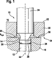
図1から、公知先行技術による燃料インジェクタに用いられるカップラの実施形態を知ることができる。 From FIG. 1, an embodiment of a coupler used in a fuel injector according to the known prior art can be seen.
図1から明らかであるように、燃料インジェクタ10は、特にニードル状に形成された噴射弁部材12を有している。このニードル状に形成された噴射弁部材12はノズルボディ18の孔14内にガイドされている。燃料インジェクタ10は中空室16を有しており、この中空室16内にはシステム圧psysが形成されている。このシステム圧psysは、例えば高圧圧送ユニットによって蓄圧体(コモンレール)内に形成される圧力レベルに相応している。ノズルボディ18は孔14を有しており、この孔14内には、特にニードル状に形成された噴射弁部材12がガイドされている。また、ノズルボディ18は端面20を有している。特にニードル状に形成された噴射弁部材12の軸線は符号22によって示されていて、弁ピストン24の軸線に対して同軸的に延びている。弁ピストン24は端面26を有しており、この端面26は、特にニードル状に形成された噴射弁部材12の一方の端面28に向かい合って位置している。弁ピストン24は、カップラスリーブ30によって取り囲まれている。
As is clear from FIG. 1, the
弁ピストン24と、この弁ピストンを取り囲むカップラスリーブ30とを有するカップラによって、アクチュエータ、例えば電磁石またはピエゾアクチュエータのストローク運動が、特にニードル状に形成された噴射弁部材12に伝達される。
By means of a coupler having a
カップラスリーブ30は、第1の端面32と第2の端面34とを有している。カップラスリーブ30の第2の端面34には食付き縁部(Beisskante)36が形成されている。この食込み縁部36によって、カップラスリーブ30がノズルボディ18の端面20に当て付けられている。カップラスリーブ30は、図1に示されていないプリロードエレメントを介してプリロード力によって負荷されている。図1から明らかであるように、ハイドロリック式のカップラの構成部材である弁ピストン24はネック38を有している。
The
図1に示された燃料インジェクタ10は、カップラスリーブ30の内径と噴射弁部材12の外径との間に0.3mmのオーダの直径差を有している。このガイドクリアランスによってシステム圧psysに対して約100μsだけ遅れてカップラ圧が形成される。0.3mmのオーダの直径差から生じるガイドクリアランスに基づき、弁ピストン24のストローク運動の間、所定の燃料量が流入する。カップラスリーブ30が各噴射後にノズルボディ18の端面20から持ち上がるので、カップラスリーブ30は各噴射後に僅かに異なる位置をとる。この場合、ガイドギャップの形状が噴射過程ごとに変化する。カップラ体積内に流入する燃料量は、有利にはニードル状に形成された噴射弁部材12の閉鎖運動と閉鎖時期とに影響を与る。このことは、慣用のインジェクタに比べて著しく大きいストロークばらつきにつながる。この慣用の漏れ随伴の燃料インジェクタでは、弁ピストン24が、戻し圧(低圧)下にある燃料によって取り囲まれている。これにより、一方では、制御室から弁ピストンガイドに沿って、他方では噴射弁部材12に沿った高圧室から噴射弁部材12のガイドに沿って、弁ピストンを取り囲む体積内への連続的な漏れが生じる。
The
これと異なり、漏れなしのインジェクタでは、弁ピストンを取り囲む体積が高圧領域に接続される。これにより、互いに相対的に可動な構成部材のガイドでの圧力勾配が生じないので、漏れが起こらない。 In contrast, in a leak-free injector, the volume surrounding the valve piston is connected to the high pressure region. As a result, no pressure gradient occurs at the guides of the components that are relatively movable with respect to each other, so that no leakage occurs.
図2から、本発明により提案されたカップラの断面図を知ることができる。図2から明らかであるように、燃料インジェクタ10は、ニードル状に形成された噴射弁部材12を有しており、この噴射弁部材12はノズルボディ18の孔14内にガイドされている。燃料インジェクタ10の中空室16内にはシステム圧psysが形成されている。ノズルボディ18の端面20にはカップラスリーブ30が当て付けられている。このカップラスリーブの第1の端面は符号32によって特徴付けられており、第2の端面は符号34によって特徴付けられている。図1に示されたカップラスリーブ30と異なり、本発明により提案された燃料インジェクタ10に使用されるカップラスリーブ30は、ほぼ方形の横断面を有している。有利にはニードル状に形成された噴射弁部材12の軸線は符号22によって示されている。ほぼ方形の横断面を有するカップラスリーブ30の第2の端面34には食付き縁部36が位置している。カップラスリーブ30は、当付け力50の作用に基づきノズルボディ18の端面20に当て付けられている。さらに、図2から明らかであるように、カップラスリーブ30の内径46と弁ピストン24の外径との間のガイドクリアランス40が5μm以下に寸法設定されている。弁ピストン24は、この弁ピストン24がカップラスリーブ30内にガイドされている領域、つまり弁ピストン24のガイド長さ58に、カップラスリーブ30に対する5μm以下のガイドクリアランス40を考慮して、直径46を有している。カップラの弁ピストン24には移行領域42が暗示されており、この移行領域42の内部では、弁ピストン24の直径が、ノズルボディ18に形成された孔14の直径に相応しかつ噴射弁部材12の外径44にほぼ相応する直径に移行している。図2から明らかであるように、有利にはニードル状に形成された噴射弁部材12と、カップラの弁ピストン24とのストローク段階の図示の期間では、弁ピストン24の端面26が、有利にはニードル状に形成された噴射弁部材12の一方の端面28に接触している。
From FIG. 2 it can be seen a cross-sectional view of the coupler proposed by the present invention. As is clear from FIG. 2, the
カップラスリーブ30と、弁ピストン24の外周面と、ノズルボディ18の端面20との間にはカップラ室54が形成されており、このカップラ室54は、40mm3以下のオーダにあるカップラ体積を有している。カップラスリーブ30の内径46と、弁ピストン24の外径44との間のガイドクリアランス40が最小の5μm以下の場合には、システム圧psysが形成された中空室16において、システム圧psys下にある無視できる程度の燃料量がカップラ室54内に流入する。カップラ室54内に流入する体積流は、ガイド長さ58にわたる圧力差に比例しているが、ガイドクリアランス40の3乗には反比例しているので、ガイドクリアランス40を5μm未満の値に減ずることは、流入する体積を減少させるために極めて効果的である。ノズルボディ18に設けられた、カップラの弁ピストン24の一部ならびに有利にはニードル状に形成された噴射弁部材12をガイドする孔14は、端面20に斜め面取り部52を有している。カップラの弁ピストン24の端面26には、同様に斜め面取り部56が形成されていてよい。有利には、弁ピストン24の端面26もしくは有利にはニードル状に形成された噴射弁部材の端面28は平らに形成される。図2に示された燃料インジェクタ10は、一方では、カップラスリーブ30の内径46と、有利にはニードル状に形成された噴射弁部材12の外径44との間に0.2mm〜0mmの間の直径差を有している。この残された僅かな直径差に基づき、有利にはニードル状に形成された噴射弁部材12のストローク運動の間のカップラの内部での圧力低下が減ぜられる。カップラスリーブ30の内径46と、有利にはニードル状に形成された噴射弁部材12の外径44との間の直径差が0mmである場合、圧力差Δpは、もはや座からの、有利にはニードル状に形成された噴射弁部材12持ち上がりの間しか生じず、有利にはニードル状に形成された噴射弁部材12が座絞り領域から離れるやいなや再び消失する。カップラスリーブ30と弁ピストン24との間のガイドクリアランス40は5μm以下の値に減ぜられており、これにより、減ぜられたガイドクリアランス40を介してカップラ室54内に流入する体積流が有効に減ぜられている。さらに、図2に示されたように、カップラスリーブ30内でカップラの弁ピストン24をガイドしているガイド長さ58が、図1に示されたガイド長さに比べて著しく延長されている。弁ピストンに対する、有利にはニードル状に形成された噴射弁部材12の可能な限り遅れなしの追動を達成するために、カップラスリーブ30の内部の燃料体積が、燃料インジェクタの閉鎖された状態で40mm3以下の値に制限される。
A
10 燃料インジェクタ、 12 噴射弁部材、 14 孔、 16 中空室、 18 ノズルボディ、 20 端面、 22 軸線、 24 弁ピストン、 26 端面、 28 端面、 30 カップラスリーブ、 32 第1の端面、 34 第2の端面、 36 食付き縁部、 38 ネック、 40 ガイドクリアランス、 42 移行領域、 44 外径、 46 直径、 50 当て付け力、 52 斜め面取り部、 54 カップラ室、 56 斜め面取り部、 58 ガイド長さ
DESCRIPTION OF
Claims (9)
Applications Claiming Priority (3)
| Application Number | Priority Date | Filing Date | Title |
|---|---|---|---|
| DE102007002282A DE102007002282A1 (en) | 2007-01-16 | 2007-01-16 | Fuel injector with coupler |
| DE102007002282.6 | 2007-01-16 | ||
| PCT/EP2007/064641 WO2008086941A1 (en) | 2007-01-16 | 2007-12-28 | Fuel injector comprising a coupler |
Publications (2)
| Publication Number | Publication Date |
|---|---|
| JP2010515855A JP2010515855A (en) | 2010-05-13 |
| JP5002023B2 true JP5002023B2 (en) | 2012-08-15 |
Family
ID=39481238
Family Applications (1)
| Application Number | Title | Priority Date | Filing Date |
|---|---|---|---|
| JP2009545135A Active JP5002023B2 (en) | 2007-01-16 | 2007-12-28 | Fuel injector with coupler |
Country Status (9)
| Country | Link |
|---|---|
| US (1) | US7992810B2 (en) |
| EP (1) | EP2126333B1 (en) |
| JP (1) | JP5002023B2 (en) |
| CN (1) | CN101583790A (en) |
| AT (1) | ATE483106T1 (en) |
| BR (1) | BRPI0718797B1 (en) |
| DE (2) | DE102007002282A1 (en) |
| RU (1) | RU2452867C2 (en) |
| WO (1) | WO2008086941A1 (en) |
Families Citing this family (2)
| Publication number | Priority date | Publication date | Assignee | Title |
|---|---|---|---|---|
| EP3499213B1 (en) * | 2017-12-15 | 2021-09-15 | Microjet Technology Co., Ltd. | Particulate matter measuring device |
| CN114135430B (en) * | 2021-12-08 | 2023-01-06 | 一汽解放汽车有限公司 | Fuel injection valve |
Family Cites Families (9)
| Publication number | Priority date | Publication date | Assignee | Title |
|---|---|---|---|---|
| DE3767260D1 (en) * | 1986-09-25 | 1991-02-14 | Ganser Hydromag | FUEL INJECTION VALVE. |
| DE4026721A1 (en) * | 1990-08-24 | 1992-02-27 | Bosch Gmbh Robert | INJECTION VALVE AND METHOD FOR PRODUCING AN INJECTION VALVE |
| DE19500706C2 (en) | 1995-01-12 | 2003-09-25 | Bosch Gmbh Robert | Metering valve for dosing liquids or gases |
| DE19650865A1 (en) | 1996-12-07 | 1998-06-10 | Bosch Gmbh Robert | magnetic valve |
| DE19946827C1 (en) * | 1999-09-30 | 2001-06-21 | Bosch Gmbh Robert | Valve for controlling liquids |
| DE10145620B4 (en) * | 2001-09-15 | 2006-03-02 | Robert Bosch Gmbh | Valve for controlling fluids |
| DE102004035280A1 (en) | 2004-07-21 | 2006-03-16 | Robert Bosch Gmbh | Fuel injector with direct multi-stage injection valve element control |
| DE102005007543A1 (en) | 2005-02-18 | 2006-08-24 | Robert Bosch Gmbh | Fuel injector with direct needle control for an internal combustion engine |
| RU2280781C1 (en) * | 2005-03-05 | 2006-07-27 | Федеральное государственное образовательное учреждение высшего профессионального образования Воронежский государственный аграрный университет им. К.Д. Глинки | Electrohydraulic nozzle for diesel engine |
-
2007
- 2007-01-16 DE DE102007002282A patent/DE102007002282A1/en not_active Withdrawn
- 2007-12-28 DE DE502007005235T patent/DE502007005235D1/en active Active
- 2007-12-28 US US12/520,563 patent/US7992810B2/en active Active
- 2007-12-28 BR BRPI0718797-1A patent/BRPI0718797B1/en active IP Right Grant
- 2007-12-28 JP JP2009545135A patent/JP5002023B2/en active Active
- 2007-12-28 RU RU2009131122/06A patent/RU2452867C2/en active
- 2007-12-28 WO PCT/EP2007/064641 patent/WO2008086941A1/en active Application Filing
- 2007-12-28 EP EP07858229A patent/EP2126333B1/en active Active
- 2007-12-28 CN CNA2007800499959A patent/CN101583790A/en active Pending
- 2007-12-28 AT AT07858229T patent/ATE483106T1/en active
Also Published As
| Publication number | Publication date |
|---|---|
| ATE483106T1 (en) | 2010-10-15 |
| JP2010515855A (en) | 2010-05-13 |
| RU2009131122A (en) | 2011-02-27 |
| EP2126333A1 (en) | 2009-12-02 |
| DE102007002282A1 (en) | 2008-07-17 |
| BRPI0718797A2 (en) | 2013-12-03 |
| BRPI0718797B1 (en) | 2018-08-07 |
| CN101583790A (en) | 2009-11-18 |
| WO2008086941A1 (en) | 2008-07-24 |
| US7992810B2 (en) | 2011-08-09 |
| EP2126333B1 (en) | 2010-09-29 |
| DE502007005235D1 (en) | 2010-11-11 |
| RU2452867C2 (en) | 2012-06-10 |
| US20100090032A1 (en) | 2010-04-15 |
Similar Documents
| Publication | Publication Date | Title |
|---|---|---|
| US7870847B2 (en) | Fuel injector comprising a pressure-compensated control valve | |
| US6796543B2 (en) | Electromagnetic valve for controlling a fuel injection of an internal combustion engine | |
| US7383819B1 (en) | Electromagnetic valve device and fuel injection apparatus with the valve device | |
| US20070023542A1 (en) | Fuel injector with variable actuator stroke transmission | |
| JPS63201362A (en) | Piezoelectric control valve controlling fuel injection through injection valve for internal combustion engine | |
| JP2010007667A (en) | Fuel injection device having high operation stability for internal combustion engine | |
| EP1163440B1 (en) | Fuel injector | |
| RU2517518C2 (en) | Fuel injector with electromagnet armature composed of two parts | |
| CN107532555B (en) | High-pressure fuel pump | |
| JP2010507746A (en) | Injector with axially pressure compensated control valve | |
| JP2003172232A (en) | Injector with solenoid valve for controlling injection valve | |
| US6811138B2 (en) | Magnetic valve for controlling an injection valve of an internal combustion engine | |
| JP2006509964A (en) | Collision-free electromagnetic actuator for injection valve | |
| US6837451B2 (en) | Seat/slide valve with pressure-equalizing pin | |
| JP5002023B2 (en) | Fuel injector with coupler | |
| US20080169357A1 (en) | Fuel Injector That Opens In Two Stages | |
| KR102139895B1 (en) | Injection valve with magnetic ring element | |
| JP2019124182A (en) | Fuel injection device and fuel injection system | |
| CN105658946B (en) | Fuel injector | |
| EP2829718B1 (en) | Injector Arrangement | |
| JP2014501359A (en) | Electronically controlled fuel injection valve | |
| JP2004517266A (en) | 3 port 2 position switching valve | |
| US20050034707A1 (en) | Control valve for fuel injector and method of use | |
| US6662783B2 (en) | Digital valve | |
| JP3818206B2 (en) | Fuel injection valve |
Legal Events
| Date | Code | Title | Description |
|---|---|---|---|
| RD04 | Notification of resignation of power of attorney |
Free format text: JAPANESE INTERMEDIATE CODE: A7424 Effective date: 20101228 Free format text: JAPANESE INTERMEDIATE CODE: A7424 Effective date: 20101227 |
|
| A131 | Notification of reasons for refusal |
Free format text: JAPANESE INTERMEDIATE CODE: A131 Effective date: 20110713 |
|
| A601 | Written request for extension of time |
Free format text: JAPANESE INTERMEDIATE CODE: A601 Effective date: 20111013 |
|
| A602 | Written permission of extension of time |
Free format text: JAPANESE INTERMEDIATE CODE: A602 Effective date: 20111020 |
|
| A601 | Written request for extension of time |
Free format text: JAPANESE INTERMEDIATE CODE: A601 Effective date: 20111114 |
|
| A602 | Written permission of extension of time |
Free format text: JAPANESE INTERMEDIATE CODE: A602 Effective date: 20111121 |
|
| A601 | Written request for extension of time |
Free format text: JAPANESE INTERMEDIATE CODE: A601 Effective date: 20111213 |
|
| A602 | Written permission of extension of time |
Free format text: JAPANESE INTERMEDIATE CODE: A602 Effective date: 20111227 |
|
| A521 | Request for written amendment filed |
Free format text: JAPANESE INTERMEDIATE CODE: A523 Effective date: 20120111 |
|
| TRDD | Decision of grant or rejection written | ||
| A01 | Written decision to grant a patent or to grant a registration (utility model) |
Free format text: JAPANESE INTERMEDIATE CODE: A01 Effective date: 20120419 |
|
| A01 | Written decision to grant a patent or to grant a registration (utility model) |
Free format text: JAPANESE INTERMEDIATE CODE: A01 |
|
| A61 | First payment of annual fees (during grant procedure) |
Free format text: JAPANESE INTERMEDIATE CODE: A61 Effective date: 20120518 |
|
| R150 | Certificate of patent or registration of utility model |
Ref document number: 5002023 Country of ref document: JP Free format text: JAPANESE INTERMEDIATE CODE: R150 Free format text: JAPANESE INTERMEDIATE CODE: R150 |
|
| FPAY | Renewal fee payment (event date is renewal date of database) |
Free format text: PAYMENT UNTIL: 20150525 Year of fee payment: 3 |
|
| R250 | Receipt of annual fees |
Free format text: JAPANESE INTERMEDIATE CODE: R250 |
|
| R250 | Receipt of annual fees |
Free format text: JAPANESE INTERMEDIATE CODE: R250 |
|
| R250 | Receipt of annual fees |
Free format text: JAPANESE INTERMEDIATE CODE: R250 |
|
| R250 | Receipt of annual fees |
Free format text: JAPANESE INTERMEDIATE CODE: R250 |
|
| R250 | Receipt of annual fees |
Free format text: JAPANESE INTERMEDIATE CODE: R250 |
|
| R250 | Receipt of annual fees |
Free format text: JAPANESE INTERMEDIATE CODE: R250 |
|
| R250 | Receipt of annual fees |
Free format text: JAPANESE INTERMEDIATE CODE: R250 |
|
| R250 | Receipt of annual fees |
Free format text: JAPANESE INTERMEDIATE CODE: R250 |
|
| R250 | Receipt of annual fees |
Free format text: JAPANESE INTERMEDIATE CODE: R250 |