JP5000963B2 - Magnetic resonance imaging system - Google Patents
Magnetic resonance imaging system Download PDFInfo
- Publication number
- JP5000963B2 JP5000963B2 JP2006266162A JP2006266162A JP5000963B2 JP 5000963 B2 JP5000963 B2 JP 5000963B2 JP 2006266162 A JP2006266162 A JP 2006266162A JP 2006266162 A JP2006266162 A JP 2006266162A JP 5000963 B2 JP5000963 B2 JP 5000963B2
- Authority
- JP
- Japan
- Prior art keywords
- phase
- magnetic resonance
- magnetic field
- pulse
- image
- Prior art date
- Legal status (The legal status is an assumption and is not a legal conclusion. Google has not performed a legal analysis and makes no representation as to the accuracy of the status listed.)
- Expired - Fee Related
Links
Images


Description
本発明は、磁気共鳴イメージング装置(以下、MRI装置という)に係わり、特に、スピンエコー信号(SE)シーケンスでエコー信号計測を行う際に発生するアーチファクトの影響を排除し、画質の改善を可能とするMRI装置に関する。 The present invention relates to a magnetic resonance imaging apparatus (hereinafter referred to as an MRI apparatus), and in particular, eliminates the influence of artifacts that occur when performing echo signal measurement in a spin echo signal (SE) sequence, and enables improvement in image quality. It relates to the MRI device.
MRI装置は、核磁気共鳴(NMR)現象を利用して被検体中の所望の検査部位に相当する断面における原子核スピン(以下スピンと称する)の密度分布、緩和時間分布等を計測して、その計測データから被検体の検査部位を画像表示するものである。 The MRI apparatus uses the nuclear magnetic resonance (NMR) phenomenon to measure the density distribution, relaxation time distribution, etc. of nuclear spins (hereinafter referred to as spins) in the cross section corresponding to the desired examination site in the subject. An image of the examination site of the subject is displayed from the measurement data.
MRI装置による撮像法として、SEシーケンスによるエコー信号計測がある。このSEシーケンスでは、π/2パルスにより横磁化を励起し、πパルスによりこの横磁化を再収束させてエコー信号を計測する。 As an imaging method using an MRI apparatus, there is an echo signal measurement using an SE sequence. In this SE sequence, transverse magnetization is excited by a π / 2 pulse, and this transverse magnetization is refocused by a π pulse, and an echo signal is measured.
しかし、π/2パルスの影響を受けずに留まった縦磁化成分の一部が、エコー信号計測のための印加されたπパルスの不完全性によって横磁化に回転される。この不必要に発生した横磁化によるFID信号が、πパルスにより形成されるエコー信号に混入して、画像上にアーチファクトをもたらす。このFID信号は、位相エンコードが印加されていないため、画像上の位相エンコード方向に1本の線状アーチファクトとして現れる。 However, a portion of the longitudinal magnetization component that remains unaffected by the π / 2 pulse is rotated to transverse magnetization by imperfection of the applied π pulse for echo signal measurement. This unnecessarily generated FID signal due to transverse magnetization is mixed in an echo signal formed by the π pulse, and causes artifacts on the image. Since the FID signal is not applied with phase encoding, it appears as a single linear artifact in the phase encoding direction on the image.
この線状アーチファクトは、π/2パルスの印加位相を励起毎にπずつ変化させてエコー信号計測することによって、位相エンコード方向に見た周波数を最高周波数として計測することが可能であり、最高周波数として計測されたエコー信号は画像の最端部に配置することが可能である(例えば、特許文献1)。その結果、この線状アーチファクトは実質的に画像診断の障害とならないようにすることが可能である。
しかしこのような手法を用いても、オフセンターFOV計測の場合には、画像から線状アーチファクトを除去することができない。オフセンタFOV計測とは、静磁場中心と関心領域(計測領域)中心とが一致しない状態の計測であり、この計測で初期的に得られた画像は、関心領域が画像中心に存在せずにずれた位置となるが、画像処理によってシフト処理をすることにより関心領域が画像中心に配置される画像を得る。この場合、画像最端部に配置した線状アーチファクトも同様にシフト処理されるため関心領域内に混入してしまう。 However, even if such a method is used, in the case of off-center FOV measurement, linear artifacts cannot be removed from the image. Off-center FOV measurement is a measurement in which the center of the static magnetic field does not coincide with the center of interest (measurement region), and the image initially obtained by this measurement is shifted because the region of interest does not exist at the center of the image. However, an image in which the region of interest is arranged at the center of the image is obtained by performing shift processing by image processing. In this case, the linear artifact arranged at the end of the image is also shifted in the same manner, and therefore mixed in the region of interest.
本発明は、このようなSEシーケンスによる計測において、π/2パルスの影響を受けずに留まった縦磁化成分に基づいて画像中に混入するアーチファクトを、画像の任意の位置に移動することが可能であるMRI装置を提供することを目的とする。 The present invention can move artifacts mixed in an image to an arbitrary position in the image based on the longitudinal magnetization component that remains unaffected by the π / 2 pulse in the measurement by such SE sequence. An object of the present invention is to provide an MRI apparatus.
上記目的を達成するために、本発明のMRI装置は次の様に構成される。即ち、静磁場を発生する静磁場発生手段、静磁場中に置かれた被検体に対して、高周波電磁波を印加する送信手段、静磁場に磁場勾配を与える傾斜磁場発生手段、被検体から発生する核磁気共鳴信号を計測する受信手段、これら送信手段、傾斜磁場発生手段および受信手段をスピンエコーパルスシーケンスに従い制御する制御手段、計測された磁気共鳴共信号に基づいて画像処理を行う画像処理手段を備え、制御手段は、静磁場の中心に対する計測領域中心のずれ量に応じて高周波磁場の位相および核磁気共鳴信号の計測位相を調整する手段を備えたことを特徴とする。 In order to achieve the above object, the MRI apparatus of the present invention is configured as follows. That is, a static magnetic field generating means for generating a static magnetic field, a transmitting means for applying a high-frequency electromagnetic wave to a subject placed in the static magnetic field, a gradient magnetic field generating means for giving a magnetic field gradient to the static magnetic field, and generated from the subject Receiving means for measuring nuclear magnetic resonance signals, control means for controlling these transmitting means, gradient magnetic field generating means and receiving means in accordance with a spin echo pulse sequence, and image processing means for performing image processing based on the measured magnetic resonance co-signals The control means includes means for adjusting the phase of the high-frequency magnetic field and the measurement phase of the nuclear magnetic resonance signal in accordance with the amount of deviation of the center of the measurement region from the center of the static magnetic field.
本発明のMRI装置によれば、オフセンタFOV計測における画像のずれ量に基づき励起パルスの位相を調整する手段を設けたことにより、SEシーケンスで、π/2パルスに起因して画像内に発生する線状アーチファクトを、位相エンコード方向の任意の位置に配置することができる。これにより被検体が位相エンコード方向に磁場中心からずれた位置での計測を行う場合でも、常に線状アーチファクトを画像の最端部に配置することができ、その悪影響を被検体画像に及ぼさないような計測が可能となる。結果的により高画質なSEシーケンス画像を取得することができる。 According to the MRI apparatus of the present invention, by providing means for adjusting the phase of the excitation pulse based on the image shift amount in the off-center FOV measurement, the SE sequence is generated in the image due to the π / 2 pulse. Linear artifacts can be placed at any position in the phase encoding direction. As a result, even when the subject performs measurement at a position deviated from the center of the magnetic field in the phase encoding direction, the linear artifact can always be arranged at the extreme end of the image so that the adverse effect is not exerted on the subject image. Measurement is possible. As a result, an SE sequence image with higher image quality can be acquired.
以下、本発明のMRI装置の一実施形態を図面に基づいて説明する。
図1は本発明を適用したMRI装置を示す全体構成のブロック説明図である。このMRI装置は、主として中央処理装置(CPU)1と、シーケンサ2と、送信系3と、静磁場発生磁石4と、受信系5と、信号処理系6とを備えている。
Hereinafter, an embodiment of the MRI apparatus of the present invention will be described with reference to the drawings.
FIG. 1 is a block diagram of an overall configuration showing an MRI apparatus to which the present invention is applied. This MRI apparatus mainly includes a central processing unit (CPU) 1, a
中央処理装置(CPU)1は、本発明に基づくプログラムに従ってシーケンサ2、送信系3、受信系5、信号処理系6の各々を制御するものである。シーケンサ2は、中央処理装置1からの制御指令に基づいて動作し、被検体7の断層画像のデータ収集に必要な種々の命令を送信系3、静磁場発生磁石4の傾斜磁場発生系(12,13)および受信系6に送るようにしている。
The central processing unit (CPU) 1 controls each of the
送信系3は、高周波発信器8と変調器9と高周波コイルとしての照射コイル11を有し、シーケンサ2の指令により高周波発信器8からの高周波パルスを変調器9で振幅変調し、この振幅変調された高周波パルスを高周波増幅器10を介し増幅して照射コイル11に供給することにより、所定のパルス状の電磁波を被検体7に照射するようにしている。この高周波パルスの印加位相は中央処理装置1によって制御される。
The
静磁場発生磁石4は、被検体7の回りに任意の方向に均一な静磁場を発生させるためのものである。この静磁場発生磁石4の内部には、照射コイル11の他、傾斜磁場を発生させる傾斜磁場コイル13と、受信系5の受信コイル14が設置されている。
傾斜磁場発生系は、互いに直交するデカルト座標軸方向にそれぞれ独立に傾斜磁場を印加する傾斜磁場コイル13と、傾斜磁場コイル13に電流を供給する傾斜磁場電源12とから構成され、傾斜磁場電源12は前述のようにシーケンサ2により制御される。
The static magnetic field generating magnet 4 is for generating a uniform static magnetic field around the subject 7 in an arbitrary direction. Inside the static magnetic field generating magnet 4, in addition to the
The gradient magnetic field generation system includes a gradient
受信系5は、高周波コイルとしての受信コイル14と受信コイル14に接続された増幅器15と直交位相検波器16とA/D変換器17とを有し、被検体7からのNMR信号を受信コイル14が検出すると、その信号を増幅器16、直交位相検波器16、A/D変換器17を介しデジタル量に変換するとともに、シーケンサ2からの指令によるタイミングで直交位相検波器16によってサンプリングされた二系列の収集データに変換して中央処理装置1に送るようにしている。この信号計測の位相は、高周波パルスの印加位相と同様に中央処理装置1によって制御される。
The
信号処理系6は、磁気ディスク20、光ディスク19等の外部記憶装置と、CRT等からなるディスプレイ18とを有し、受信系5からのデータが中央処理装置1に入力されると、中央処理装置1が信号処理、画像再構成等の処理を実行し、その結果である被検体7の所望の断面像をディスプレイ18に表示するとともに、外部記憶装置の磁気ディスク20等に記録する。
The
図2は、このような構成における中央処理装置1にプログラムとして組み込まれた制御の手順を示す図で、SEシーケンスによりスピンエコー信号計測する場合を示す。SEシーケンスは、図3に示すようなシーケンステーブルとしてシーケンサ2内に組み込まれており、このシーケンスに基づいて高周波パルス、傾斜磁場パルスの印加タイミングおよび強度並びに信号計測のタイミングが決る。
FIG. 2 is a diagram showing a control procedure incorporated as a program in the central processing unit 1 having such a configuration, and shows a case where a spin echo signal is measured by an SE sequence. The SE sequence is incorporated in the
即ち、まず被検体のスライスを選択する傾斜磁場27とともに励起パルス24を印加し、位相エンコード傾斜磁場30および読み出し傾斜磁場31を印加し、πパルス25をスライス傾斜磁場28とともに印加する。励起パルスは通常π/2のパルスが採用される。励起パルス24印加からエコー信号時間TE後に読み出し傾斜磁場32、33を印加しながらエコー信号37を計測する。エコー時間後に印加する読み出し傾斜磁場33は、その面積(印加時間と強度の積)が、少なくともそれ以前に印加した読み出し傾斜磁場32の面積以上にする。
このようなシーケンスを所定の位相エンコード数繰り返し、計測したエコー信号から画像を再構成する。
That is, first, the
Such a sequence is repeated a predetermined number of phase encodings, and an image is reconstructed from the measured echo signals.
本発明の制御では、このようなSEシーケンスにおける励起パルスおよび信号計測の位相をオフセンタFOV計測における画像中心のシフト量に基づき調整するステップを含むことを特徴としている。 The control of the present invention includes a step of adjusting the phase of the excitation pulse and signal measurement in such an SE sequence based on the shift amount of the image center in the off-center FOV measurement.
次に図2および図3を参照して、本発明のMRI装置によるスピンエコー信号計測を説明する。
まずスピンエコー信号計測に先立ってスカウト画像を計測し、スカウト画像を元に静磁場中心に対する計測領域の位相エンコード方向のずれ量を求める(ステップ201)。このずれ量は、例えばスカウト画像上で関心領域の中心を指示することにより、中央処理装置1により自動的に求められる。MRI計測では、画像と受信した計測データの関係は二次元フーリエ変換と逆変換の関係になるため、画像の位置のずれは、受信信号の位相の回転に相当する。よって、中央処理装置1は、このずれ量をもとに位相調整量αを次式により計算する(ステップ202)。
α=(2×π×P)/FOV (1)
ここで、Pは位相エンコード方向の位置のずれ量、FOVは位相エンコード方向の撮像領域サイズを表す。また、初期位相、つまり1回目の繰り返しにおける励起パルスおよび信号計測の位相φを設定する(ステップ203)。
Next, spin echo signal measurement by the MRI apparatus of the present invention will be described with reference to FIGS.
First, a scout image is measured prior to spin echo signal measurement, and the amount of shift in the phase encoding direction of the measurement region with respect to the center of the static magnetic field is obtained based on the scout image (step 201). This deviation amount is automatically obtained by the central processing unit 1 by indicating the center of the region of interest on the scout image, for example. In MRI measurement, since the relationship between the image and the received measurement data is a relationship between two-dimensional Fourier transform and inverse transform, the image position shift corresponds to the rotation of the phase of the received signal. Therefore, the central processing unit 1 calculates the phase adjustment amount α by the following equation based on the deviation amount (step 202).
α = (2 × π × P) / FOV (1)
Here, P is the amount of position shift in the phase encoding direction, and FOV is the size of the imaging region in the phase encoding direction. Also, the initial phase, that is, the excitation pulse and signal measurement phase φ in the first iteration is set (step 203).
次に、位相エンコード毎の励起パルスの位相を求める(ステップ204,)。1回目の繰り返しにおける励起パルスの位相(つまり初期位相)をφとすると、2回目の繰り返しでは励起パルスの位相をπ+φ+αとし、3回目の繰り返しでは励起パルスの位相を2π+φ+2αとする。以下、n番目の繰り返しでは励起パルスの位相を2nπ+φ+(n-1)αとする。 Next, the phase of the excitation pulse for each phase encoding is obtained (step 204). If the phase of the excitation pulse in the first iteration (that is, the initial phase) is φ, the phase of the excitation pulse is π + φ + α in the second iteration, and the phase of the excitation pulse is 2π + φ + 2α in the third iteration. Hereinafter, in the nth iteration, the phase of the excitation pulse is 2nπ + φ + (n−1) α.
同様に、位相エンコード毎の計測位相を求める(ステップ205)。1回目の繰り返しにおける計測位相(つまり初期位相)をφとすると、2回目の繰り返しでは計測位相をπ+φ−αとし、3回目の繰り返しでは計測位相を2π+φ−2αとする。以下、n番目の繰り返しでは計測位相を2nπ+φ−(n-1)αとする。 Similarly, a measurement phase for each phase encoding is obtained (step 205). If the measurement phase (that is, the initial phase) in the first iteration is φ, the measurement phase is π + φ−α in the second iteration, and the measurement phase is 2π + φ−2α in the third iteration. Hereinafter, in the n-th iteration, the measurement phase is 2nπ + φ− (n−1) α.
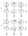
次に、図3に示すSEシーケンスを実行し、スピンエコー信号計測を行う(ステップ206)。この場合の磁化ベクトルの挙動(静磁場方向からみた平面での挙動)を図4(a)に示す。同図(b)は比較のために従来の手法における磁化ベクトルの挙動を示したものである。いずれもφ=0とした例である。また、計測位相をADで示す。 Next, the SE sequence shown in FIG. 3 is executed to perform spin echo signal measurement (step 206). FIG. 4 (a) shows the behavior of the magnetization vector in this case (behavior in a plane viewed from the direction of the static magnetic field). FIG. 2B shows the behavior of the magnetization vector in the conventional method for comparison. Both are examples in which φ = 0. The measurement phase is indicated by AD.
第1回目では、π/2パルスによってXY平面内に磁化ベクトル41が発生し、この磁化ベクトル41はπパルスで反転し磁化ベクトル42となる。このとき不要な横磁化43がXY平面内に発生する。このとき、計測位相は0とする。
位相エンコード量を変えた第2回目の計測では(図4(a)の中段)、π/2パルスの励起位相をπ反転させ、さらに上述したように位相調整量αずらして印加する。すると、XY平面では、第1回目とは逆の軸でさらにαずれた位相76で磁化ベクトル46が発生する。 続けてπパルスを第1回目と同じ位相で印加する。すると最初π/2パルスによって発生した磁化ベクトル46は磁化ベクトル47となり、第1回目とは逆で且つαだけずれた方向になる。またπパルスによって発生した不要な横磁化48は第1回目と同じ向きの磁化ベクトルとなる。このとき、計測位相は磁化ベクトル47と同じ位相とする。従って、不要な横磁化48によるFID信号の位相はπ−αとなる。
In the first time, a
In the second measurement with the phase encoding amount changed (middle stage in FIG. 4 (a)), the excitation phase of the π / 2 pulse is inverted by π, and the phase adjustment amount is shifted by α as described above. Then, in the XY plane, the
さらに位相エンコード量を変えた第3回目の計測では(図4(a)の下段)、π/2パルスの励起位相をπ反転させて元に戻し、さらに位相2αずらして印加する。するとXY平面では、第1回目と同じ軸でさらに2αずれた位相77で磁化ベクトル51が発生する。続けてπパルスは、第1回目と同じ位相で印加する。すると最初π/2パルスによって発生した磁化ベクトル51は磁化ベクトル52となり、第1回目と同じで且つ2αだけずれた方向になる。またπパルスによって発生した不要な横磁化48は第1回目と同じ向きの磁化ベクトルとなる。このとき、計測位相は磁化ベクトル52と同じ位相とする。従って、不要な横磁化48によるFID信号の位相は2π−2αとなる。
Further, in the third measurement with the phase encoding amount changed (the lower part of FIG. 4 (a)), the excitation phase of the π / 2 pulse is reversed by π, and is applied with a phase shift of 2α. Then, in the XY plane, a
エコー信号計測時にも、π/2パルスの位相回転と同じように、位相回転させてエコー信号の計測を行う。その結果、エコー信号の位相は、π/2パルスの位相回転による位相がキャンセルされて0(ゼロ)位相となるのに対し、線状アーチファクトの元となる不要な横磁化によるFID信号の位相は、計測位相の位相回転と同じように位相回転することになる。このような条件で計測したエコー信号の位相とFID信号の位相の状態を表1に示す。

表1からもわかるように、スピンエコー信号の位相が変化せず、位相エンコード方向に見た場合、直流成分となるのに対して、FID信号の位相はπずつ変化し、さらに角速度αで変化する。よって、FID信号は、デジタル的には最高周波数にさらにαに相当する分の周波数ずれた周波数として処理され画像化される。
これを図4(b)に示す従来の手法と比べると、従来の手法では最初π/2パルスによって発生した不要な横磁化ベクトル41は、エコー信号計測時には、計測毎に向きが反転するのみとなる。
As can be seen from Table 1, the phase of the spin echo signal does not change and when viewed in the phase encoding direction, it becomes a direct current component, whereas the phase of the FID signal changes by π and further changes with the angular velocity α. To do. Therefore, the FID signal is digitally processed and imaged as a frequency shifted by a frequency corresponding to α from the highest frequency.
Compared to the conventional method shown in FIG. 4 (b), the unnecessary
最後に、以上のような計測によって得られた信号から画像再構成する(ステップ206)。 図5に、画像再構成して得られる画像の例を示す。ただし、図5は、位相エンコード毎のFID信号の位相と、周波数エンコード軸に沿った画像信号プロファイルを示す。図5(a)は、従来のπ/2パルスの位相を反転させる方法により得られるFID信号の位相と、このような計測によって得られた信号から画像再構成して得られる画像の例を示す。図5(b)は、図5(a)に更にオフセンタ処理を施した例を示す。図5(c)は、本発明のπ/2パルスの位相及び計測位相をオフセット量に応じて位相回転量を付加した場合により得られるFID信号の位相と、このような計測によって得られた信号から画像再構成して得られる画像の例を示す。 Finally, an image is reconstructed from the signal obtained by the measurement as described above (step 206). FIG. 5 shows an example of an image obtained by image reconstruction. However, FIG. 5 shows the phase of the FID signal for each phase encoding and the image signal profile along the frequency encoding axis. FIG. 5 (a) shows an example of the image obtained by image reconstruction from the phase of the FID signal obtained by the conventional method of inverting the phase of the π / 2 pulse and the signal obtained by such measurement. . FIG. 5B shows an example in which an off-center process is further applied to FIG. FIG. 5 (c) shows the phase of the FID signal obtained by adding the phase rotation amount according to the offset amount to the phase of the π / 2 pulse and the measurement phase of the present invention, and the signal obtained by such measurement. An example of an image obtained by image reconstruction from FIG.
図5(a)に示すように、位相エンコード毎にπ変化したのみの位相情報(501)を持つ成分をフーリエ変換すると、画像の位相エンコード方向における最高周波数上に結像される(502)。これに対して図5(b) に示すように、オフセンタ計測を実施した場合、撮像対象物も最高周波数上に結像することがある(503)。この時、FID信号は図5(a)同様、画像の位相エンコード方向における最高周波数上に結像される(504)。オフセンタ再構成を施すと撮像対象物はオフセンタ処理が施され、画像中心に移動する(505)。同様にFID信号に対してもオフセンタ処理が施されるため、FID信号つまり線状アーチファクトが診断領域に混入する(506)。 As shown in FIG. 5 (a), when a component having phase information (501) that has only changed by π for each phase encoding is Fourier transformed, an image is formed on the highest frequency in the phase encoding direction of the image (502). On the other hand, as shown in FIG. 5 (b), when off-center measurement is performed, the imaging object may also form an image on the highest frequency (503). At this time, the FID signal is imaged on the highest frequency in the phase encoding direction of the image (504) as in FIG. 5 (a). When off-center reconstruction is performed, the imaging object is subjected to off-center processing and moves to the center of the image (505). Similarly, since the off-center processing is performed on the FID signal, the FID signal, that is, the linear artifact is mixed in the diagnosis area (506).
これに対し、図5(c)の位相情報を持つFID信号(507)は、図5(a)の位相情報に加えてすでにオフセンタ再構成と同等の位相情報を持つため、画像の位相エンコード方向では、最高周波数から、オフセンタ周波数分ずれた周波数の位置に結像される(508)。その後、オフセンタ再構成が施されるため、撮像対象は中心に、線状アーチファクトは常に画像最端に移動することとなる(509)。このように、FID信号の最高周波数からのずれαは、位相エンコード方向のFOVのずれ量に相当するため、線状アーチファクトはそのずれ量だけ位相エンコード方向にシフトして配置される。一方、撮像された被検体も同じ量だけずれている。従って最終的にシフト処理を行い得られた画像においては、線状アーチファクトは画像の位相エンコード方向の最端部に配置され、被検体画像に影響を及ぼすことはない。 On the other hand, the FID signal (507) having the phase information of FIG. 5 (c) already has the same phase information as the off-center reconstruction in addition to the phase information of FIG. Then, an image is formed at a position shifted from the highest frequency by an off-center frequency (508). Thereafter, since off-center reconstruction is performed, the imaging target is always moved to the center, and the linear artifact is always moved to the end of the image (509). Thus, since the shift α from the highest frequency of the FID signal corresponds to the shift amount of the FOV in the phase encoding direction, the linear artifact is shifted and arranged in the phase encoding direction by the shift amount. On the other hand, the imaged subject is also shifted by the same amount. Therefore, in the image finally obtained by performing the shift process, the linear artifact is arranged at the extreme end in the phase encoding direction of the image and does not affect the subject image.
以上は、初期位相φ=0とした場合について、本発明の一実施形態を具体的に説明したが、φが0(ゼロ)でない場合は、上記具体例の全てをφだけ回転させれば同じことなので、φが0(ゼロ)でない場合もφ=0の場合と同様に本発明を実施できる。 The above has specifically described one embodiment of the present invention in the case where the initial phase φ = 0, but when φ is not 0 (zero), the same is true if all the above specific examples are rotated by φ. Therefore, even when φ is not 0 (zero), the present invention can be implemented in the same manner as when φ = 0.
1 中央処理装置(制御手段)
2 シーケンサ
3 送信系
4 静磁場発生磁石
5 受信系
6 信号処理系(画像処理手段)
7 被検体
12,13 傾斜磁場発生系
1 Central processing unit (control means)
2
7
Claims (3)
前記所定のパルスシーケンスは、高周波磁場として励起パルスと反転パルスを印加して核磁気共鳴信号を計測する際に、該励起パルスの位相と該核磁気共鳴信号の計測位相をπずつ変化させるパルスシーケンスであり、
前記制御手段は、前記静磁場の中心に対する計測領域の中心のずれ量に応じた位相制御量(α)を求めて、前記励起パルスの位相および前記核磁気共鳴信号の計測位相を制御する磁気共鳴イメージング装置において、
前記制御手段は、前記励起パルスの影響を受けずに留まった縦磁化成分の一部が前記反転パルスにより横磁化に回転されて生じたFID信号が最初の前記核磁気共鳴信号に混入することで生じる画像アーチファクトをシフトするために、前記励起パルスの印加毎又は位相エンコード毎に、前記励起パルスの位相をαずつ増加させ、前記最初の核磁気共鳴信号の計測位相をαずつ減少させることを特徴とする磁気共鳴イメージング装置。 Static magnetic field generating means for generating a static magnetic field, transmitting means for applying a high-frequency electromagnetic wave to a subject placed in the static magnetic field, gradient magnetic field generating means for giving a magnetic field gradient to the static magnetic field, generated from the subject Receiving means for measuring the nuclear magnetic resonance signal, control means for controlling these transmitting means, gradient magnetic field generating means and receiving means in accordance with a predetermined pulse sequence, and image processing for performing image processing based on the measured nuclear magnetic resonance co-signal With means ,
The predetermined pulse sequence is a pulse sequence that changes the phase of the excitation pulse and the measurement phase of the nuclear magnetic resonance signal by π when measuring the nuclear magnetic resonance signal by applying an excitation pulse and an inversion pulse as a high-frequency magnetic field. And
The control means obtains a phase control amount (α) corresponding to a shift amount of the center of the measurement region with respect to the center of the static magnetic field, and controls the phase of the excitation pulse and the measurement phase of the nuclear magnetic resonance signal. In the imaging device,
The control means is such that a part of the longitudinal magnetization component that remains without being influenced by the excitation pulse is rotated into transverse magnetization by the inversion pulse, and the FID signal generated by mixing in the first nuclear magnetic resonance signal. In order to shift the generated image artifact, the phase of the excitation pulse is increased by α each time the excitation pulse is applied or phase encoded, and the measurement phase of the first nuclear magnetic resonance signal is decreased by α. Magnetic resonance imaging apparatus.
前記制御手段は、前記反転パルスの位相を一定にすることを特徴とする磁気共鳴イメージング装置。The magnetic resonance imaging apparatus, wherein the control means makes the phase of the inversion pulse constant.
前記画像のアーチファクトは、線状アーチファクトであり、The image artifact is a linear artifact,
前記制御手段は、前記計測領域の中心を画像の中心にシフトし且つ前記線状アーチファクトを画像の端部にシフトするように、前記励起パルスの位相および前記最初の核磁気共鳴信号の計測位相を制御することを特徴とする磁気共鳴イメージング装置。The control means changes the phase of the excitation pulse and the measurement phase of the first nuclear magnetic resonance signal so as to shift the center of the measurement region to the center of the image and shift the linear artifact to the edge of the image. A magnetic resonance imaging apparatus characterized by controlling.
Priority Applications (1)
| Application Number | Priority Date | Filing Date | Title |
|---|---|---|---|
| JP2006266162A JP5000963B2 (en) | 2006-09-29 | 2006-09-29 | Magnetic resonance imaging system |
Applications Claiming Priority (1)
| Application Number | Priority Date | Filing Date | Title |
|---|---|---|---|
| JP2006266162A JP5000963B2 (en) | 2006-09-29 | 2006-09-29 | Magnetic resonance imaging system |
Publications (2)
| Publication Number | Publication Date |
|---|---|
| JP2008080030A JP2008080030A (en) | 2008-04-10 |
| JP5000963B2 true JP5000963B2 (en) | 2012-08-15 |
Family
ID=39351467
Family Applications (1)
| Application Number | Title | Priority Date | Filing Date |
|---|---|---|---|
| JP2006266162A Expired - Fee Related JP5000963B2 (en) | 2006-09-29 | 2006-09-29 | Magnetic resonance imaging system |
Country Status (1)
| Country | Link |
|---|---|
| JP (1) | JP5000963B2 (en) |
Families Citing this family (1)
| Publication number | Priority date | Publication date | Assignee | Title |
|---|---|---|---|---|
| CN101612042B (en) * | 2008-06-26 | 2012-03-07 | 株式会社东芝 | Magnetic resonance imaging apparatus and magnetic resonance imaging method |
Family Cites Families (9)
| Publication number | Priority date | Publication date | Assignee | Title |
|---|---|---|---|---|
| JPS62122645A (en) * | 1985-11-22 | 1987-06-03 | 株式会社東芝 | Magnetic resonance imaging apparatus |
| JPH0295346A (en) * | 1988-09-30 | 1990-04-06 | Shimadzu Corp | Mr device |
| JP2890200B2 (en) * | 1989-08-29 | 1999-05-10 | ジーイー横河メディカルシステム株式会社 | Nuclear magnetic resonance tomography system |
| JP3181285B2 (en) * | 1990-10-16 | 2001-07-03 | 株式会社東芝 | MRI data collection method |
| JP3183915B2 (en) * | 1991-09-03 | 2001-07-09 | 株式会社東芝 | Magnetic resonance imaging equipment |
| JPH05277086A (en) * | 1992-04-02 | 1993-10-26 | Yokogawa Medical Syst Ltd | Echo collection method applying ir method of mri apparatus |
| JPH10179537A (en) * | 1996-12-20 | 1998-07-07 | Toshiba Corp | Magnetic resonance imaging device and magnetic resonance imaging method |
| JP4400957B2 (en) * | 1999-09-30 | 2010-01-20 | 株式会社日立メディコ | Magnetic resonance imaging system |
| JP4192139B2 (en) * | 2004-10-27 | 2008-12-03 | ジーイー・メディカル・システムズ・グローバル・テクノロジー・カンパニー・エルエルシー | Phase cycling method and magnetic resonance imaging apparatus in SSFP pulse sequence |
-
2006
- 2006-09-29 JP JP2006266162A patent/JP5000963B2/en not_active Expired - Fee Related
Also Published As
| Publication number | Publication date |
|---|---|
| JP2008080030A (en) | 2008-04-10 |
Similar Documents
| Publication | Publication Date | Title |
|---|---|---|
| JP2001505811A (en) | Method and apparatus for measuring temperature distribution of an object by magnetic resonance | |
| US20160170001A1 (en) | Magnetic resonance imaging apparatus and magnetic resonance imaging method | |
| WO2011007691A1 (en) | Magnetic resonance imaging device and magnetic resonance imaging method | |
| US6906515B2 (en) | Magnetic resonance imaging device and method | |
| JP3276669B2 (en) | Magnetic resonance imaging equipment | |
| JP5808659B2 (en) | Magnetic resonance imaging apparatus and T1ρ imaging method | |
| JPH0365971B2 (en) | ||
| JP5000963B2 (en) | Magnetic resonance imaging system | |
| JP4400957B2 (en) | Magnetic resonance imaging system | |
| JP4229254B2 (en) | Magnetic resonance imaging system | |
| US11885864B2 (en) | Magnetic resonance imaging apparatus and method of controlling the same | |
| JP3526347B2 (en) | Magnetic resonance imaging system | |
| JP3167038B2 (en) | Magnetic resonance imaging equipment | |
| JP5942265B2 (en) | Magnetic resonance imaging apparatus and RF pulse control method | |
| JPH0568672A (en) | Gradient magnetic field impressing method for magnetic resonance imaging device | |
| JP4349646B2 (en) | Nuclear magnetic resonance imaging system | |
| JP3909571B2 (en) | Magnetic resonance imaging system | |
| JP3332951B2 (en) | Magnetic resonance imaging equipment | |
| JP2002165774A (en) | Magnetic resonance imaging device | |
| JP4079399B2 (en) | Magnetic resonance imaging system | |
| JP2016131847A (en) | Magnetic resonance imaging apparatus and magnetic resonance imaging method | |
| JP3322695B2 (en) | Magnetic resonance imaging equipment | |
| JP3317552B2 (en) | MRI equipment | |
| JP2005028019A (en) | Magnetic resonance imaging device | |
| JPH0430830A (en) | Magnetic resonance imaging apparatus |
Legal Events
| Date | Code | Title | Description |
|---|---|---|---|
| A621 | Written request for application examination |
Free format text: JAPANESE INTERMEDIATE CODE: A621 Effective date: 20090929 |
|
| A977 | Report on retrieval |
Free format text: JAPANESE INTERMEDIATE CODE: A971007 Effective date: 20110916 |
|
| A131 | Notification of reasons for refusal |
Free format text: JAPANESE INTERMEDIATE CODE: A131 Effective date: 20110921 |
|
| A521 | Written amendment |
Free format text: JAPANESE INTERMEDIATE CODE: A523 Effective date: 20111108 |
|
| TRDD | Decision of grant or rejection written | ||
| A01 | Written decision to grant a patent or to grant a registration (utility model) |
Free format text: JAPANESE INTERMEDIATE CODE: A01 Effective date: 20120515 |
|
| A01 | Written decision to grant a patent or to grant a registration (utility model) |
Free format text: JAPANESE INTERMEDIATE CODE: A01 |
|
| A61 | First payment of annual fees (during grant procedure) |
Free format text: JAPANESE INTERMEDIATE CODE: A61 Effective date: 20120517 |
|
| R150 | Certificate of patent or registration of utility model |
Free format text: JAPANESE INTERMEDIATE CODE: R150 Ref document number: 5000963 Country of ref document: JP Free format text: JAPANESE INTERMEDIATE CODE: R150 |
|
| FPAY | Renewal fee payment (event date is renewal date of database) |
Free format text: PAYMENT UNTIL: 20150525 Year of fee payment: 3 |
|
| S111 | Request for change of ownership or part of ownership |
Free format text: JAPANESE INTERMEDIATE CODE: R313111 |
|
| S533 | Written request for registration of change of name |
Free format text: JAPANESE INTERMEDIATE CODE: R313533 |
|
| R350 | Written notification of registration of transfer |
Free format text: JAPANESE INTERMEDIATE CODE: R350 |
|
| LAPS | Cancellation because of no payment of annual fees |