JP5000511B2 - Improved LED flashlight - Google Patents
Improved LED flashlight Download PDFInfo
- Publication number
- JP5000511B2 JP5000511B2 JP2007527879A JP2007527879A JP5000511B2 JP 5000511 B2 JP5000511 B2 JP 5000511B2 JP 2007527879 A JP2007527879 A JP 2007527879A JP 2007527879 A JP2007527879 A JP 2007527879A JP 5000511 B2 JP5000511 B2 JP 5000511B2
- Authority
- JP
- Japan
- Prior art keywords
- light source
- reflector
- opening
- parabolic
- contour surface
- Prior art date
- Legal status (The legal status is an assumption and is not a legal conclusion. Google has not performed a legal analysis and makes no representation as to the accuracy of the status listed.)
- Expired - Fee Related
Links
Images


Classifications
-
- F—MECHANICAL ENGINEERING; LIGHTING; HEATING; WEAPONS; BLASTING
- F21—LIGHTING
- F21L—LIGHTING DEVICES OR SYSTEMS THEREOF, BEING PORTABLE OR SPECIALLY ADAPTED FOR TRANSPORTATION
- F21L4/00—Electric lighting devices with self-contained electric batteries or cells
- F21L4/02—Electric lighting devices with self-contained electric batteries or cells characterised by the provision of two or more light sources
- F21L4/022—Pocket lamps
- F21L4/027—Pocket lamps the light sources being a LED
-
- F—MECHANICAL ENGINEERING; LIGHTING; HEATING; WEAPONS; BLASTING
- F21—LIGHTING
- F21L—LIGHTING DEVICES OR SYSTEMS THEREOF, BEING PORTABLE OR SPECIALLY ADAPTED FOR TRANSPORTATION
- F21L4/00—Electric lighting devices with self-contained electric batteries or cells
-
- F—MECHANICAL ENGINEERING; LIGHTING; HEATING; WEAPONS; BLASTING
- F21—LIGHTING
- F21L—LIGHTING DEVICES OR SYSTEMS THEREOF, BEING PORTABLE OR SPECIALLY ADAPTED FOR TRANSPORTATION
- F21L4/00—Electric lighting devices with self-contained electric batteries or cells
- F21L4/04—Electric lighting devices with self-contained electric batteries or cells characterised by the provision of a light source housing portion adjustably fixed to the remainder of the device
-
- F—MECHANICAL ENGINEERING; LIGHTING; HEATING; WEAPONS; BLASTING
- F21—LIGHTING
- F21V—FUNCTIONAL FEATURES OR DETAILS OF LIGHTING DEVICES OR SYSTEMS THEREOF; STRUCTURAL COMBINATIONS OF LIGHTING DEVICES WITH OTHER ARTICLES, NOT OTHERWISE PROVIDED FOR
- F21V13/00—Producing particular characteristics or distribution of the light emitted by means of a combination of elements specified in two or more of main groups F21V1/00 - F21V11/00
- F21V13/02—Combinations of only two kinds of elements
- F21V13/04—Combinations of only two kinds of elements the elements being reflectors and refractors
- F21V13/045—Combinations of only two kinds of elements the elements being reflectors and refractors for portable lighting devices
-
- F—MECHANICAL ENGINEERING; LIGHTING; HEATING; WEAPONS; BLASTING
- F21—LIGHTING
- F21V—FUNCTIONAL FEATURES OR DETAILS OF LIGHTING DEVICES OR SYSTEMS THEREOF; STRUCTURAL COMBINATIONS OF LIGHTING DEVICES WITH OTHER ARTICLES, NOT OTHERWISE PROVIDED FOR
- F21V14/00—Controlling the distribution of the light emitted by adjustment of elements
- F21V14/04—Controlling the distribution of the light emitted by adjustment of elements by movement of reflectors
- F21V14/045—Controlling the distribution of the light emitted by adjustment of elements by movement of reflectors in portable lighting devices
-
- F—MECHANICAL ENGINEERING; LIGHTING; HEATING; WEAPONS; BLASTING
- F21—LIGHTING
- F21V—FUNCTIONAL FEATURES OR DETAILS OF LIGHTING DEVICES OR SYSTEMS THEREOF; STRUCTURAL COMBINATIONS OF LIGHTING DEVICES WITH OTHER ARTICLES, NOT OTHERWISE PROVIDED FOR
- F21V23/00—Arrangement of electric circuit elements in or on lighting devices
- F21V23/04—Arrangement of electric circuit elements in or on lighting devices the elements being switches
- F21V23/0414—Arrangement of electric circuit elements in or on lighting devices the elements being switches specially adapted to be used with portable lighting devices
- F21V23/0428—Arrangement of electric circuit elements in or on lighting devices the elements being switches specially adapted to be used with portable lighting devices the switch being part of, or disposed on the lamp head portion thereof
-
- F—MECHANICAL ENGINEERING; LIGHTING; HEATING; WEAPONS; BLASTING
- F21—LIGHTING
- F21V—FUNCTIONAL FEATURES OR DETAILS OF LIGHTING DEVICES OR SYSTEMS THEREOF; STRUCTURAL COMBINATIONS OF LIGHTING DEVICES WITH OTHER ARTICLES, NOT OTHERWISE PROVIDED FOR
- F21V29/00—Protecting lighting devices from thermal damage; Cooling or heating arrangements specially adapted for lighting devices or systems
- F21V29/50—Cooling arrangements
- F21V29/70—Cooling arrangements characterised by passive heat-dissipating elements, e.g. heat-sinks
-
- F—MECHANICAL ENGINEERING; LIGHTING; HEATING; WEAPONS; BLASTING
- F21—LIGHTING
- F21V—FUNCTIONAL FEATURES OR DETAILS OF LIGHTING DEVICES OR SYSTEMS THEREOF; STRUCTURAL COMBINATIONS OF LIGHTING DEVICES WITH OTHER ARTICLES, NOT OTHERWISE PROVIDED FOR
- F21V3/00—Globes; Bowls; Cover glasses
-
- F—MECHANICAL ENGINEERING; LIGHTING; HEATING; WEAPONS; BLASTING
- F21—LIGHTING
- F21V—FUNCTIONAL FEATURES OR DETAILS OF LIGHTING DEVICES OR SYSTEMS THEREOF; STRUCTURAL COMBINATIONS OF LIGHTING DEVICES WITH OTHER ARTICLES, NOT OTHERWISE PROVIDED FOR
- F21V31/00—Gas-tight or water-tight arrangements
- F21V31/005—Sealing arrangements therefor
-
- F—MECHANICAL ENGINEERING; LIGHTING; HEATING; WEAPONS; BLASTING
- F21—LIGHTING
- F21V—FUNCTIONAL FEATURES OR DETAILS OF LIGHTING DEVICES OR SYSTEMS THEREOF; STRUCTURAL COMBINATIONS OF LIGHTING DEVICES WITH OTHER ARTICLES, NOT OTHERWISE PROVIDED FOR
- F21V5/00—Refractors for light sources
- F21V5/04—Refractors for light sources of lens shape
-
- F—MECHANICAL ENGINEERING; LIGHTING; HEATING; WEAPONS; BLASTING
- F21—LIGHTING
- F21V—FUNCTIONAL FEATURES OR DETAILS OF LIGHTING DEVICES OR SYSTEMS THEREOF; STRUCTURAL COMBINATIONS OF LIGHTING DEVICES WITH OTHER ARTICLES, NOT OTHERWISE PROVIDED FOR
- F21V7/00—Reflectors for light sources
- F21V7/04—Optical design
- F21V7/06—Optical design with parabolic curvature
-
- H—ELECTRICITY
- H05—ELECTRIC TECHNIQUES NOT OTHERWISE PROVIDED FOR
- H05B—ELECTRIC HEATING; ELECTRIC LIGHT SOURCES NOT OTHERWISE PROVIDED FOR; CIRCUIT ARRANGEMENTS FOR ELECTRIC LIGHT SOURCES, IN GENERAL
- H05B45/00—Circuit arrangements for operating light-emitting diodes [LED]
- H05B45/30—Driver circuits
- H05B45/395—Linear regulators
-
- H—ELECTRICITY
- H05—ELECTRIC TECHNIQUES NOT OTHERWISE PROVIDED FOR
- H05B—ELECTRIC HEATING; ELECTRIC LIGHT SOURCES NOT OTHERWISE PROVIDED FOR; CIRCUIT ARRANGEMENTS FOR ELECTRIC LIGHT SOURCES, IN GENERAL
- H05B45/00—Circuit arrangements for operating light-emitting diodes [LED]
- H05B45/50—Circuit arrangements for operating light-emitting diodes [LED] responsive to malfunctions or undesirable behaviour of LEDs; responsive to LED life; Protective circuits
- H05B45/56—Circuit arrangements for operating light-emitting diodes [LED] responsive to malfunctions or undesirable behaviour of LEDs; responsive to LED life; Protective circuits involving measures to prevent abnormal temperature of the LEDs
-
- F—MECHANICAL ENGINEERING; LIGHTING; HEATING; WEAPONS; BLASTING
- F21—LIGHTING
- F21V—FUNCTIONAL FEATURES OR DETAILS OF LIGHTING DEVICES OR SYSTEMS THEREOF; STRUCTURAL COMBINATIONS OF LIGHTING DEVICES WITH OTHER ARTICLES, NOT OTHERWISE PROVIDED FOR
- F21V29/00—Protecting lighting devices from thermal damage; Cooling or heating arrangements specially adapted for lighting devices or systems
- F21V29/50—Cooling arrangements
- F21V29/502—Cooling arrangements characterised by the adaptation for cooling of specific components
- F21V29/507—Cooling arrangements characterised by the adaptation for cooling of specific components of means for protecting lighting devices from damage, e.g. housings
-
- F—MECHANICAL ENGINEERING; LIGHTING; HEATING; WEAPONS; BLASTING
- F21—LIGHTING
- F21Y—INDEXING SCHEME ASSOCIATED WITH SUBCLASSES F21K, F21L, F21S and F21V, RELATING TO THE FORM OR THE KIND OF THE LIGHT SOURCES OR OF THE COLOUR OF THE LIGHT EMITTED
- F21Y2115/00—Light-generating elements of semiconductor light sources
- F21Y2115/10—Light-emitting diodes [LED]
-
- Y—GENERAL TAGGING OF NEW TECHNOLOGICAL DEVELOPMENTS; GENERAL TAGGING OF CROSS-SECTIONAL TECHNOLOGIES SPANNING OVER SEVERAL SECTIONS OF THE IPC; TECHNICAL SUBJECTS COVERED BY FORMER USPC CROSS-REFERENCE ART COLLECTIONS [XRACs] AND DIGESTS
- Y02—TECHNOLOGIES OR APPLICATIONS FOR MITIGATION OR ADAPTATION AGAINST CLIMATE CHANGE
- Y02B—CLIMATE CHANGE MITIGATION TECHNOLOGIES RELATED TO BUILDINGS, e.g. HOUSING, HOUSE APPLIANCES OR RELATED END-USER APPLICATIONS
- Y02B20/00—Energy efficient lighting technologies, e.g. halogen lamps or gas discharge lamps
- Y02B20/30—Semiconductor lamps, e.g. solid state lamps [SSL] light emitting diodes [LED] or organic LED [OLED]
Landscapes
- Engineering & Computer Science (AREA)
- General Engineering & Computer Science (AREA)
- Arrangement Of Elements, Cooling, Sealing, Or The Like Of Lighting Devices (AREA)
- Non-Portable Lighting Devices Or Systems Thereof (AREA)
Description
本発明は、懐中電灯や懐中電灯用部品等を含む携帯型の照明装置に関する。 The present invention relates to a portable lighting device including a flashlight, a flashlight component, and the like.
発光ダイオード(LED)は、時計の照明、リモコンの信号の送信、大型テレビの画面における画像の構成等、様々な分野で使用されている。最近になって、特に、発光ダイオードは、懐中電灯のような携帯型の照明装置に使用されている。その理由として、発光ダイオードには、従来の懐中電灯に通常使用されていた白熱電球と比較して、壊れにくく、耐久性に優れているという利点があるからである。 Light emitting diodes (LEDs) are used in various fields such as clock lighting, remote control signal transmission, and image composition on a large television screen. Recently, in particular, light emitting diodes have been used in portable lighting devices such as flashlights. The reason for this is that light emitting diodes have the advantage that they are less likely to break and have better durability than incandescent bulbs that are normally used in conventional flashlights.
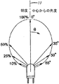
上記のように、発光ダイオードには、白熱電球よりも耐久性に優れているという利点があるが、主要光源として発光ダイオードを使用する照明装置についても、様々な改良を施す必要がある。例えば、現在販売されているLED懐中電灯では、質の高い光線を遠距離照射するのに不向きであった。その理由として、LEDランプを使用した場合、LEDの位置に対して180度以内の角度で光を拡散して照射するためである。図1は、通常のLEDランプの明度及び照射範囲を示している。通常のLEDランプは、発光ダイオードと、該発光ダイオードを覆うレンズ部とを有する。通常のLEDランプでは、光線は、LEDランプより略円錐状に拡散し、明度(パーセント表示)は、通常、主軸11に集中し、球形角度θが大きくなるに従って、非線形に減少する。従来のLED懐中電灯には、主軸の周辺に集中する光線を効果的に獲得することができる反射器とランプの結合体が設けられていなかった。したがって、従来のLEDランプでは、周辺領域を照射するのには適していたけれども、光線を照射する場合、わずかな距離しか照射することができなかった。
As described above, the light emitting diode has an advantage that it is more durable than the incandescent bulb. However, it is necessary to make various improvements to the lighting device that uses the light emitting diode as a main light source. For example, currently sold LED flashlights are unsuitable for irradiating high-quality light over long distances. The reason is that when an LED lamp is used, the light is diffused and irradiated at an angle of 180 degrees or less with respect to the position of the LED. FIG. 1 shows the brightness and irradiation range of a normal LED lamp. A normal LED lamp has a light emitting diode and a lens portion that covers the light emitting diode. In a normal LED lamp, light rays are diffused in a substantially conical shape as compared with the LED lamp, and the lightness (percentage display) is normally concentrated on the
前記問題点を解決するため、複数の発光ダイオード又は発光ダイオードランプと白熱電球の結合体が使用されている照明装置がある。しかしながら、前記照明装置では、構造の複雑化、電力の浪費、製造コストの増大を招くという問題がある。したがって、本発明は、光学性能を改善し、かつ、質の高い光線を照射することができる省エネルギーLED照明装置を提供することを課題とする。 In order to solve the above problems, there is an illumination device in which a plurality of light emitting diodes or a combination of a light emitting diode lamp and an incandescent lamp is used. However, the lighting device has problems that the structure is complicated, the power is wasted, and the manufacturing cost is increased. Therefore, an object of the present invention is to provide an energy-saving LED lighting device that can improve optical performance and emit high-quality light.
また、発光ダイオードのような光源に改良が加えられるので、携帯型照明装置の使用時に解決すべき別の課題は、上昇した光源の熱を効率よく分散させることにある。したがって、本発明は、携帯型照明装置の光源の熱を効率よく分散させる結合体を備える。また、本発明は、光源の熱量を抑制し、かつ、光を照射するのに使用する電力を抑制する手段を備える。 In addition, since the light source such as the light emitting diode is improved, another problem to be solved when the portable lighting device is used is to efficiently dissipate the heat of the raised light source. Accordingly, the present invention includes a combined body that efficiently dissipates heat from the light source of the portable lighting device. In addition, the present invention includes means for suppressing the amount of heat of the light source and suppressing the power used for irradiating light.
本発明は、光学性能を改善した携帯型の照明装置であって、照明装置の性能を向上させることを課題とする。 The present invention is a portable lighting device with improved optical performance, and an object of the present invention is to improve the performance of the lighting device.
本発明の一実施形態に係る照明装置は、電力源と、光源と、反射器と、保持部とを備える。前記反射器は、開口第1端部と、第2端部と、前記2つの端部の間に延在する放物線状輪郭面とを備える。また、前記反射器は、前記放物線状輪郭面の外側に位置する焦点を備える。特に、前記放物線状輪郭面によれば、前記光源から発する明るさが高めの光線を平行にする効率を容易に向上させることができる。前記保持部は、前記光源の光を前記反射器で反射させるために、前記反射器に対して前記光源を保持する。前記光源と前記反射器の相対的な位置は、移動可能にしてもよい。本発明の一実施形態では、並列配置した電池を保持するのに、独自の電力源アセンブリが設けられる。 An illumination device according to an embodiment of the present invention includes a power source, a light source, a reflector, and a holding unit. The reflector includes an opening first end, a second end, and a parabolic contour surface extending between the two ends. The reflector includes a focal point located outside the parabolic contour surface. In particular, according to the parabolic contour surface, it is possible to easily improve the efficiency of collimating light beams with high brightness emitted from the light source. The holding unit holds the light source with respect to the reflector in order to reflect the light of the light source with the reflector. The relative position of the light source and the reflector may be movable. In one embodiment of the invention, a unique power source assembly is provided to hold the batteries arranged in parallel.
任意の構成としては、前記反射器の前記放物線状輪郭面は、焦点の長さとなる頂点から焦点までの距離を0.020インチから0.050インチまで又は0.035とする、方程式r2=4fzからなる輪郭面を構成する。あるいは、頂点から小開口部までの距離と焦点の長さとの比率は、1.5:1から6.5:1まで、3.0:1から3.4:1まで、又は3.0:1から3.2:1までとする。照明装置は、パルス電流又は熱調整を行うパルス電流を光源に伝達する電流調整回路を備えていてもよい。 Optionally, the parabolic contour surface of the reflector is such that the distance from the apex to the focal point, which is the focal length, is 0.020 inch to 0.050 inch or 0.035, the equation r 2 = A contour surface composed of 4 fz is formed. Alternatively, the ratio of the distance from the apex to the small aperture and the focal length is from 1.5: 1 to 6.5: 1, from 3.0: 1 to 3.4: 1, or 3.0: 1 to 3.2: 1. The illumination device may include a current adjustment circuit that transmits a pulse current or a pulse current for performing thermal adjustment to the light source.
懐中電灯の場合、本発明は、携帯型電力源と、光源と、曲面構成の移動可能な反射器とを備える。前記光源は、LEDと、レンズとを備え、光が、LEDの位置に対して180°以下の角度で前記光源から略放射状に照射される。前記移動可能な反射器は、放物線状輪郭面と、該放物線状輪郭面の外側に位置する焦点とを備える。また、反射器は、放物線形の主軸に対して平行な方向に移動可能であってもよい。また、懐中電灯は、前記光源に熱伝導可能に連結されるヒートシンクを備えていてもよい。 In the case of a flashlight, the present invention comprises a portable power source, a light source, and a movable reflector with a curved configuration. The light source includes an LED and a lens, and light is emitted from the light source substantially radially at an angle of 180 ° or less with respect to the position of the LED. The movable reflector includes a parabolic contour surface and a focal point located outside the parabolic contour surface. The reflector may be movable in a direction parallel to the parabolic main axis. Further, the flashlight may include a heat sink connected to the light source so as to conduct heat.
本発明の別の態様では、懐中電灯は、携帯型電力源と、LEDランプと、該LEDランプの第1リード線と携帯型電力源とを電気的に連結する放熱ハウジングを備える電気回路とを備える。また、前記放熱ハウジングは、前記LEDランプに熱伝導可能に連結されて、前記LEDランプの熱を実質的に分散させる。 In another aspect of the present invention, a flashlight includes a portable power source, an LED lamp, and an electric circuit including a heat dissipation housing that electrically connects the first lead wire of the LED lamp and the portable power source. Prepare. The heat radiating housing is connected to the LED lamp so as to conduct heat, and substantially dissipates heat of the LED lamp.
さらに、本発明の別の態様では、改良された電力源アセンブリは、並列配置して保持された電池を備える。 Furthermore, in another aspect of the invention, the improved power source assembly comprises batteries held in parallel.
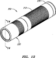
図2及び図13は、本発明の各実施形態に係る照明装置を斜視図で示したのであり、前記照明装置は、懐中電灯10及び200として構成されている。懐中電灯10及び200は、本発明の様々な特徴を有している。本発明の特徴は、本発明の好ましい実施形態を示した後述の詳細な説明と添付の図面によって明らかとなる。しかしながら、本発明は、本明細書に記載された懐中電灯に限定して理解されるべきではなく、本発明には、1つ以上の発明の特徴を有する照明装置が含まれると理解されるべきである。また、本発明は、後述の照明装置の全ての特徴を対象とするものであると理解されるべきである。
2 and 13 are perspective views of the lighting device according to each embodiment of the present invention, and the lighting device is configured as a
図2及び図3を参照すると、懐中電灯10は、ヘッドアセンブリ20と、光源14と、端キャップアセンブリ30とを備える。ヘッドアセンブリ20及び光源14は、筒体12の前端に配置される。端キャップアセンブリ30は、筒体12の後端を閉鎖する。
2 and 3, the
図3及び図4を参照すると、筒体12は、例えば、電池16のような少なくとも1つの電力源を収容するように構成された中空構造である。図示の実施形態においては、筒体12は、前端の外径に形成された前方ネジ部18と、後端の内径に形成された後方ネジ部22とを備える。筒体12は、前方テーパー部26と後方テーパー部27とからなる縮径領域24を備える。図示の実施形態のように、電池16は、直列に3つ配置した状態で筒体12に収容されるのが好ましい。本発明の属する技術分野における当業者であれば、筒体12が以下のように構成されてもよいということが理解できる。筒体12に収容される電池の個数は、2つ以下であってもよいし、4つ以上であってもよい。また、電池の配置は、直列と並列のいずれであってもよい。さらに、他の携帯型の電力源が、直列又は並列に配置した状態で筒体12に収容されてもよい。電池16は、アルカリ乾電池であるのが好ましい。
Referring to FIGS. 3 and 4, the
図3及び図5を参照すると、端キャップアセンブリ30は、端キャップ28と、導電性バネ32と、端キャップ用接触材38とを備える。端キャップ28は、筒体12の内側に形成された後方ネジ部22と対応して嵌合する外側ネジ領域34を備えるのが好ましい。本発明の属する技術分野における当業者であれば、端キャップ28を筒体12に固定するのに、他の適切な手段を採用してもよいことを理解することができる。
3 and 5, the
防水シールとしての機能を果たすように、シール部材36が、端キャップ28と筒体12との間の接触面に設けられる。シール部材36は、Oリング等のシール手段で構成される。シール部材36は、一方向弁であることが好ましく、これにより、外部から懐中電灯10の内部に水が浸入するのを防ぐとともに、懐中電灯の内部の余剰圧力を外部に逃がすことができる。放射状隆起部35が、端キャップ28と筒体12との間の接触面に設けられる。前記放射状隆起部35によって、筒体12の端部が、隣接する端キャップ28のフランジに対して気密シールを構成し、懐中電灯内部の余剰圧力のガス流を妨げるようなことがない。
A
懐中電灯における一方向弁の構成及び用途は、アンソニー・マグリカ(Anthony Maglica)に特許付与された米国特許5003440号、米国特許5113326号、米国特許5207502号、米国特許5349506号、及び米国特許5485360号にさらに詳細に開示されており、前記文献に言及することで本明細書に組み入れられている。 One-way valve configurations and applications in flashlights are described in US Pat. No. 5,0034,340, US Pat. No. 5,113,326, US Pat. No. 5,207,502, US Pat. No. 5,349,506, and US Pat. No. 5,485,360, patented to Anthony Maglica. Further details are disclosed and are incorporated herein by reference to the literature.
図5を参照すると、端キャップ用接触材38は、導電性バネ32と端キャップ28との間に配置される。導電性バネ32は、端キャップ用接触材38と電池16のケース電極に電気的に連結される。端キャップ用接触材38は、導電性バネ32と筒体12に電気的に連結される。
Referring to FIG. 5, the end
図6を参照すると、端キャップ用接触材38は、リング部39と、2つの延在片41とを備える。2つの延在片41は、180°間隔で配置され、リング部39の外周部から略垂直に延在する。延在片41は、リング部39の外周部よりも外側に延在した外側延在部43をそれぞれ備える。外側延在部43が設けられていることにより、端キャップアセンブリ30が筒体12に固定された場合、延在片41が、筒体12の内径部と摩擦接触して、電気的に連結される。このように、端キャップ28を何ら電気的に接触させることなく電池16と筒体12との間の電気的接触を提供できる一つの方法が、図示の実施形態に開示されている。したがって、必要に応じて、例えば、プラスチック材やゴム等の非導電材で端キャップ28を製造してもよい。
Referring to FIG. 6, the end
変形例として、電池16と筒体12との間の電気的接触を提供するのに、端キャップ用挿入材が使用されてもよい。前記端キャップ用挿入材は、米国特許4819141号、米国特許4823242号、米国特許4864474号、米国特許5003440号、米国特許5008785号、米国特許5113326号、米国特許5121308号、米国特許5193898号、米国特許5207502号、米国特許5267130号、米国特許5349506号、米国特許5455752号、米国特許5485360号、米国特許5528472号、米国特許5722765号、米国特許5836672号、及び米国特許6086219号に図示及び説明されており、前記文献に言及することで本明細書に組み入れられている。
As an alternative, an end cap insert may be used to provide electrical contact between the
変形例として、接触スリーブを筒体に設け、前記接触スリーブが端キャップ用接触材38の延在片41に嵌合して、電気経路を提供するようにしてもよい。前記接触スリーブは、アンソニー・マグリカに特許付与された米国特許4656565号及び米国特許4851974号に開示されており、前記文献に言及することで本明細書に組み入れられている。また、別の変形例として、接触片を筒体に設け、前記接触片が延在片41に嵌合して、電気経路を提供するようにしてもよい。前記接触片は、米国特許6585391号に開示されている。前記接触スリーブ又は前記接触片が設けられる場合、プラスチック材やゴム等の非導電材で筒体を製造してもよい。
As a modified example, a contact sleeve may be provided on the cylinder, and the contact sleeve may be fitted to the extending
変形例として、端キャップ用接触材38を除外して端キャップアセンブリ30を構成し、端キャップ28を導電体として使用してもよい。また、別の変形例として、端キャップアセンブリ30が筒体12に取り付けられると、導電性バネ32が電池16と端キャップ28との間の電気経路を形成するようにしてもよい。前記の場合には、端キャップ28と筒体12との間にも、相互の接触面及び螺合した相互のネジ部又は前記接触面と前記ネジ部のいずれか一方を介して、電気経路がさらに形成される。電気が流れやすいように、端キャップや筒体の接触面に施された陽極処理等の表面処理を除去する。前記変形例においては、端キャップ28は、例えばアルミニウム等の導電材で製造される。
As a modification, the
図3を参照すると、端キャップアセンブリについていかなる構成を採用しても、導電性バネ32は、電池16を懐中電灯10の前方に付勢する。その結果、後側の電池の中心電極は、前側のケース電極と電気的に接触する。このように、筒体12に収容された電池16は、電気的に連結される。図4を参照すると、最前列の電池16の中心電極は、スイッチアセンブリ40と接触している。
Referring to FIG. 3, the
図4を参照すると、スイッチアセンブリ40は、筒体12の周囲に配置され、特に、反射器に対して光源14の位置を保持するものである。光源14は、第1電極58と第2電極59とを備える。
Referring to FIG. 4, the
光源14は、光を照射するのに適した装置であればよく、例えば、光源14には、LEDランプ、白熱電球、アークランプが使用される。図示の実施形態では、光源14は、180°以下の球面角度で略放射状に光を照射するLEDランプであるのが好ましい。光源14として適するのは、カリフォルニア州サンホセのルミレッズ・ライティング社(Lumileds Lighting)製のLEDランプLXHL−PW01である。
The
スイッチアセンブリ40は、光源14を保持することを特徴とする。特に、スイッチアセンブリ40は、光源14の電気回路の接続及び中断を容易に行うことができることを特徴とする。スイッチアセンブリ40は、光源14の熱を効果的に分散させることを特徴とする。
The
図7を参照すると、スイッチアセンブリ40は、上方絶縁体42と、スイッチサブアセンブリ60とを備える。スイッチサブアセンブリ60は、放熱ハウジング44と、サーキットアセンブリ50と、上方導電性バネ52と、電力源接触材54と、下方絶縁体56とを備える。
Referring to FIG. 7, the
特に、サーキットアセンブリ50は、光源14に流れる電気を制御するのが好ましい。図示の例では、サーキットアセンブリ50は、サーキットボード62と、接触プラグ64と、第1接触片46と、第2接触片48とを備える。
In particular, the
サーキットボード62は、光源14に供給する電流を制御するのに適した電流調整回路を備える。電流調整回路は、電池16からの電流をパルス電流に変換するのが好ましい。また、必要に応じて、光源14に供給されるパルス電流のデューティサイクルは、光源14の熱の温度に従って調整されるのが好ましい。
The
図8Aを参照すると、電流調整回路15の実施態様が、ブロック図で示されている。懐中電灯の電源をオンにして電力が電流調整回路15に供給されると、パルス発生器21は、光源14に供給される電流を調整するために、電源スイッチ23を制御する。電源スイッチ23は、ゲートにパルス発生器21が接続される金属酸化膜半導体電界効果トランジスタ(MOSFET)で構成されるのが好ましい。電源スイッチ23は、他の適切な装置で構成されてもよく、例えば、トランジスタやバイポーラ接合トランジスタ等であってもよい。また、パルス発生器21は、コンパレータとダイオード・レジスタシステムとを備えるのが好ましい。
Referring to FIG. 8A, an embodiment of the
電流調整回路15は、光源14の熱を検知する感温抵抗器25を備える。感温抵抗器25は、サーミスタで構成されるのが好ましい。サーミスタは、光源14の熱を検知できるように配置される。サーミスタは、パルス発生器21に連結され、光源に供給されるパルス電流のデューティサイクルを調整する。例えば、サーミスタが光源の熱の温度の過度な上昇を検知した場合には、パルス電流のデューティサイクルを下げて光源がオーバーヒートしないようにする。一方、サーミスタが光源の熱の温度の過度な下降を検知した場合には、パルス電流のデューティサイクルを上げて光源が十分な光度とむらのない光を放つようにする。図8Bは、本発明の一実施態様に係る電流調整回路15の回路図を示したものであり、サーミスタは、T1で示されている。
The
熱調整を行うパルス電流信号で光源14に電力を供給する方が、直流信号による電力供給に比べて、いくつかの利点がある。特に、パルス電流信号によれば、光源14の熱の発生量を低減することができるので、光源14の製品寿命を延ばすことができる。また、パルス電流信号によれば、消費エネルギーを抑制し、長期間の使用が可能となるので、電池の製品寿命を延ばすことができる。さらに、パルス電流信号によれば、ピーク電流をさらに高くして光源に供給することを許容するので、光源の光の明度を上げることができる。光源14の熱の温度に従って、光源14に供給されるエネルギー量を調整すれば、光源14に熱損傷が加わるのを防ぐことができる。
Supplying power to the
本明細書に開示された電流調整回路15には、金属酸化膜半導体電界効果トランジスタ(MOSFET)と、パルス発生器と、サーミスタとが用いられているけれども、本発明は、本明細書に記載された電気部品の結合体を備える回路に限定されるものではない。本発明の属する技術分野における当業者は、電流調整回路が光源にパルス信号又は熱調整に使用するパルス信号を供給するように構成されていれば、他の構成であってもよいことを理解することができる。例えば、電流調整回路は、マイクロプロセッサとルックアップテーブルとを備えていてもよい。
Although the
図7を再度参照すると、サーキットボード62の電流調整回路15と光源14の電気的接続が容易となるように、第1接触片46及び第2接触片48が用いられる。第1接触片46及び第2接触片48は、サーキットボード62に選択的に半田付け固定されるのが好ましい。第1接触片46及び第2接触片48は、光源14の第1電極58及び第2電極59を保持するように配置される。
Referring to FIG. 7 again, the
第1接触片46は、光源14の第1電極58を摩擦保持するように構成される。図示の例においては、第1接触片46は、光源14の第1電極58を保持する一対の可撓性傾斜面66を備える。前記導電体の電気的な相互接続を実現するのに、他の適切な方法又は構成が使用されてもよい。例えば、第1電極58は、半田付けで第1接触片46に電気的に接続されてもよい。
The
第2接触片48は、光源14の第2電極59を摩擦保持するように構成され、放熱ハウジング44に電気的に連結されるように構成される。図示の例においては、第2接触片48は、一対の可撓性傾斜面67と、該可撓性傾斜面67の一方に電気的に連結される連結部材68とを備える。一対の可撓性傾斜面67は、第2電極59を保持する。前記導電体の電気的な相互接続を実現するのに、他の適切な方法又は構成が使用されてもよい。例えば、第2電極59は、半田付けで第2接触片48に電気的に接続されてもよい。
The
第2接触片48の連結部材68は、第2接触片48を放熱ハウジング44に電気的に連結する。図示の例においては、連結部材68は、放熱ハウジング44の放熱プラグ72と摩擦嵌合する。前記導電体の電気的な相互接続を実現するのに、他の適切な方法又は構成が使用されてもよい。
The connecting
第1接触片46及び第2接触片48は、所望の形状に構成されたシート状の導電材で製造される。容易にシート状の導電材を成形できるように、導電材にレリーフカットが施されていてもよい。第1接触片46及び第2接触片48は、シート状の銅合金で製造されるのが好ましい。
The
図7をさらに参照すると、サーキットアセンブリ50の接触プラグ64は、第1接触片46及び第2接触片48とは反対側の位置のサーキットボード62上に設けられている。特に、接触プラグ64は、電池16を電流調整回路15に電気的に連結するのを容易にする。図示の例においては、接触プラグ64は、電流調整回路15に選択的かつ電気的に連結される。また、接触プラグ64は、上方導電性バネ52を保持するように構成される。
Still referring to FIG. 7, the
サーキットアセンブリ50は、放熱ハウジング44の内部に配置される。図9を参照すると、具体例として、放熱ハウジング44は、中空の略円柱状に構成され、閉鎖端部を備える。特に、放熱ハウジング44は、光源14と筒体12とを熱伝導可能に連結し、光源14の第2電極59を筒体12に電気的に連結する。放射ハウジング44及び筒体12が光源14の熱の吸収・分散処理又は吸収処理と分散処理のいずれか一方に用いられることで、懐中電灯10の熱損傷に対する光源14の保護がさらに効果的なものとなる。放熱ハウジング44は、例えば、アルミニウム等の導電材で構成される。
The
図7、図9、図11及び図12を参照すると、放熱ハウジング44は、放熱プラグ72と、前面部71と、一対の開口部74と、内側段部76と、外側テーパー部78と、スナップ式取付用前方溝82と、スナップ式取付用後方溝87とを備える。開口部74は、前面部71を通って延在する。開口部74は、サーキットアセンブリ50の第1接触片46と第2接触片48とに連結するために光源14の電極を挿入することができる大きさで構成される。スナップ式取付用前方溝82は、放熱ハウジング44の軸に対して略垂直に配置された段部91を備える。スナップ式取付用前方溝82は、上方絶縁体42のロック用タブ84を保持するのに使用される。スナップ式取付用後方溝87は、放熱ハウジング44の軸に対して略垂直に配置された段部93を備える。スナップ式取付用後方溝87は、下方絶縁体56のロック用タブ79を保持するのに使用される。
Referring to FIGS. 7, 9, 11, and 12, the
内側段部76は、サーキットアセンブリ50を保持するような大きさで放熱ハウジング44に形成される。放熱ハウジング44の外側テーパー部78は、筒体12の後方テーパー部27の傾斜角度と実質的に同一となるような傾斜面で構成されるのが好ましい(図4参照)。また、放熱ハウジング44の外側テーパー部78は、筒体12の内部に一度設置されると、放熱ハウジング44を含むスイッチアセンブリ40の移動が、筒体12の後方テーパー部27により制限を受けるような大きさで構成される。
The inner stepped
図7を参照すると、上方導電性バネ52は、接触プラグ64と電力源接触材54とを電気的に連結する。図示の例においては、上方導電性バネ52は、接触プラグ64を収容できる大きさの直径で構成されたコイルバネである。上方導電性バネ52の後端は、電力源接触材54により保持される。
Referring to FIG. 7, the upper
電力源接触材54は、上方導電性バネ52と電池16とを電気的に連結する。図示の例では、電力源接触材54は、端部の一端が開口したレセプタクルであり、開口端部の周囲に形成されたフランジ81を有する。電力源接触材54は、例えば、銅合板等の導電材で構成されるのが好ましい。
The power
図7及び図11を参照すると、下方絶縁体56は、特に、サーキットアセンブリ50と、上方導電性バネ52と、放熱ハウジング44の電力源接触材54とを収容する。下方絶縁体56は、ロック用タブ79と、後面部88と、凹部89と、挿通孔83と、カウンターボアの段部85とを備える。図7は、電力源接触材54のフランジ81が下方絶縁体56の段部85と離間した状態を示している。図11は、電力源接触材54のフランジ81が下方絶縁体56の段部85と接触した状態を示している。下方絶縁体56は、例えば、プラスチック材等の非導電材で構成されるのが好ましい。
Referring to FIGS. 7 and 11, the
図11を参照すると、下方絶縁体56は、ロック用タブ79をスナップ式取付用後方溝87に嵌合させ、スナップ式取付用後方溝87の段部93で移動制限することで、放熱ハウジング44に固定される。サーキットアセンブリ50は、放熱ハウジング44の内側段部76において保持される。上方導電性バネ52の前端は、サーキットアセンブリ50の接触プラグ64よりも外側に位置する。上方導電性バネ52の後端は、電力源接触材54により保持される。電力源接触材54は、下方絶縁体56の挿通孔83に摺動可能に配置される。電力源接触材54のフランジ81は、電力源接触材54が後方に軸移動するのを規制するカウンターボアの段部85に支持される。このようにして構成された場合、上方導電性バネ52は、放熱ハウジング44の内側段部76に抗して前方にサーキットアセンブリ50を付勢する。また、上方導電性バネ52は、下方絶縁体56のカウンターボアの段部85に抗して後方に電力源接触材54も付勢する。
Referring to FIG. 11, in the
電力源接触材54の軸方向の長さは、閉鎖端部が後面部88より前方に位置し、かつ、下方絶縁体56の凹部89によって規定される包囲領域内にとどまるように構成されるのが好ましい。図示の例においては、下方絶縁体56の凹部89は、懐中電灯10の後面と対向するベース部を有する円錐台状のキャビティで構成される。下方絶縁体56の凹部89は、電池の筐体より突出して延在した中央電極の高さより深く構成される。
The axial length of the power
このようにして構成されると、電池16が下方絶縁体56の後面部88に抗して前方に押圧された場合、電池16の中央電極が電力源接触材54と接触し、図7に示すように、電力源接触材54のフランジ81が下方絶縁体56のカウンターボアの段部85より離間する。これと同時に、上方導電性バネ52が電池の中央電極に抗して後方に電力源接触材54を押圧するので、バネ付勢を利用した電池16との電気的接続が可能となる。このように、スイッチサブアセンブリ60によれば、部品相互間の電気的連結を強化する簡易な構成を提供することができるため、懐中電灯へ衝撃が加わった場合又は懐中電灯が落下した場合でさえ、筒体12の内部において電池16の突然な移動を招くことがない。さらに、上方導電性バネ52は、取扱いミスによって生じる衝撃応力を吸収することができるので、電池の中央電極や、スイッチアセンブリ50のような懐中電灯の部品に対する保護機能をさらに向上させることができる。
When configured in this way, when the
また、電力源接触材54の閉鎖端部が下方絶縁体の後面部88より懐中電灯の前方に位置しているので、電池16が、ケース電極を前向きにした状態で後方から筒体12に挿入された場合、電力源接触材54と連結することがない。電池16が正確に挿入された場合、最前列の電池の中央電極が、電力源接触材54と接触し、かつ、上方導電性バネ52を押圧する。このような構成であれば、電池の誤挿入を使用者に喚起することができ、また、電流の逆流に伴う悪影響及び損傷を引き起こすことがなく、懐中電灯内の電子部品を保護することができる。電流の逆流を防止して懐中電灯の電子部品を保護する別の実施態様においては、ダイオードが、電気回路に選択的に配置される。図8Bは、前記実施態様に係る電気回路の回路図であり、ダイオードD102−Cは、電池の誤挿入よって生じる電流の逆流を防止する。
Further, since the closed end portion of the power
次に、スイッチサブアセンブリ60の構造と構成について説明する。図3及び図4を参照すると、スイッチサブアセンブリ60は、筒体12の前端付近に設置される。スイッチサブアセンブリ60は、放熱ハウジング44の外側テーパー部78が筒体12の後方テーパー部27と接触するまで組み入れられない限り、導電性バネ32の作用で前方へ押し出す力を受ける。
Next, the structure and configuration of the
図4及び図12を参照すると、上方絶縁体42は、スイッチサブアセンブリ60と連結して、スイッチサブアセンブリ60が所定の距離以上に後方へ軸移動するのを規制する。上方絶縁体42は、放熱ハウジング44のスナップ式取付用前方溝82によりスイッチサブアセンブリ60と連結する。
Referring to FIGS. 4 and 12, the upper insulator 42 is connected to the
図7及び図12を参照すると、上方絶縁体42は、ロック用タブ84と、中央間隙部92と、テーパー部96とを備える。中央間隙部92は、光源14と第1、第2電極58,59とを放熱ハウジング44に固定するのを許容するような大きさで構成される。上方絶縁体のテーパー部96は、筒体12の前方テーパー部26の形状に対応している。図12を参照すると、上方絶縁体のロック用タブ84は、それぞれ、スナップ式取付用前方溝82に嵌合するような大きさで構成され、スナップ式取付用前方溝の段部91によって前方への移動が規制される。図4を参照すると、筒体12の内部に収容されるスイッチサブアセンブリ60に上方絶縁体42を固定することによって、上方絶縁体42は、電池16が懐中電灯10に収容されていない場合に、スイッチサブアセンブリ60が筒体12の後方へ落下するのを防止し、また、懐中電灯の後端より外側に飛び出す可能性がないようにしている。上方絶縁体42は、例えば、プラスチック材等の非導電材で構成されるのが好ましい。
Referring to FIGS. 7 and 12, the upper insulator 42 includes a
図7を参照すると、光源14は、放熱ハウジング44に熱伝導可能に連結され、サーキットアセンブリ50に電気的に連結される。図示の例においては、光源14は、第1電極58と、第2電極59と、ランプ95と、スラグ片98とを備える。光源14のスラグ片98は、光源14の熱が放熱ハウジング44に容易に伝導するように、放熱ハウジング44に固定される。熱伝導性導電接着剤層が、スラグ片98と放熱ハウジング44との間に塗布されるのが好ましい。また、スラグ片98は電気的に中性でなくてもよいので、熱伝導性導電接着剤は、電気絶縁体であるのが好ましい。光源の第1、第2電極58,59は、サーキットアセンブリの第1、第2接触片46,48とそれぞれ摩擦嵌合する。
Referring to FIG. 7, the
図4を参照すると、ヘッドアセンブリ20は、筒体12の前端に配置される。ヘッドアセンブリ20は、フェイスキャップ102と、レンズ104と、反射器106と、スリーブ108とを備える。反射器106及びレンズ104は、フェイスキャップ102によって所定の位置に保持される。フェイスキャップ102は、スリーブ108と螺合して連結される。スリーブ108は、筒体12の前方ネジ部18と螺合する内径で構成されたネジ部112を備える。前記のように構成された場合、筒体12に対してヘッドアセンブリ20を回転させると、反射器106は、懐中電灯10の軸方向に強制的に移動する。
Referring to FIG. 4, the
反射器は、携帯型の照明装置において、光の方向を変更して照射距離を延ばすのに使用される。反射器は、反射率の高い反射面を有し、光源からの光線を反射してビーム光に変えるものである。反射器は、放物線状に構成されるのが好ましい。放物線形状には、焦点から放射される光を集めて、放物線形の主軸に平行な光線として光を反射させる光学上の特徴がある。光線を平行にすることによって、分散光の照射方向が変更され、遠距離照射可能なビーム光を構成する。 A reflector is used in a portable lighting device to change the direction of light and extend the irradiation distance. The reflector has a reflective surface with high reflectivity, and reflects light rays from the light source to convert them into beam light. The reflector is preferably configured in a parabolic shape. The parabolic shape has optical features that collect light emitted from the focal point and reflect the light as light rays parallel to the parabolic principal axis. By making the light beams parallel, the irradiation direction of the dispersed light is changed, and beam light that can be irradiated over a long distance is formed.
反射器を利用するにもかかわらず、特に、LED照明装置においては、ビーム光の照射距離に関して一定の限界がある。その理由として、正確に設計された部品を効果的に組み合せて、180度以内の角度で略円錐状に照射するLEDランプの光を有効に確保する必要があるからである。LEDランプの中には、180°以上の拡散領域を有すると表示しているものものあるが、多くのLEDランプのほとんど又は全てが、180°以上の拡散領域を有しておらず(最大光度の10%にも満たない領域を含めており)、図1に見られるように、中心からの最大角度θが90°未満の拡散領域しか有していない。 Despite the use of the reflector, there is a certain limit with respect to the irradiation distance of the beam light, particularly in the LED lighting device. The reason is that it is necessary to effectively ensure the light of the LED lamp that irradiates in a substantially conical shape at an angle within 180 degrees by effectively combining precisely designed components. Some LED lamps indicate that they have a diffusion region of 180 ° or more, but most or all of the LED lamps do not have a diffusion region of 180 ° or more (maximum luminous intensity). As shown in FIG. 1, it has only a diffusion region whose maximum angle θ from the center is less than 90 °.
図4及び図10を参照すると、反射器106は、第1端部114と、第2端部116と、輪郭面118と、支持部122とを備える。図示の例においては、反射器の第1端部114は、ビーム光を照射するのに使用され、反射器の第2端部116は、輪郭面118の端部を規定する開口部を構成する。輪郭面118は、主軸121の軸周りで対称な反射面を有する放物線状領域である。
Referring to FIGS. 4 and 10, the
図10を参照すると、反射器の第2端部116は、放物線の焦点94が輪郭面118の反射面の外側に配置されるように形成される。輪郭面118は、方程式r2=4fzからなる放物線形で構成されるのが好ましく、ここで、「r」とは、軸線121を基準にした放物線状輪郭面の半径を表し、「f」とは、焦点の長さ又は放物線の頂点から焦点までの距離を表し、「z」とは、軸線121上における距離を表す。
Referring to FIG. 10, the
「f」の寸法は、0.080インチ又は0.020インチから0.050インチまで又は0.035インチであるのが好ましい。また、頂点と反射器の第2端部116との距離(図10で示した符号「s」を参照。)は、0.080インチから0.130インチまで又は0.109インチから0.115インチまで又は0.112インチであるのが好ましい。反射器の第1端部114は、0.7インチから0.8インチまで又は0.741インチから0.743インチまでの寸法で構成され、反射器の第2端部116は、0.2インチから0.3インチまで又は0.247インチから0.253インチまでの寸法で構成される。さらに、頂点から反射器の第2端部116までの距離と「f」の寸法の比率は、1.5:1以上、6.5:1以下であり、3.0:1から3.4:1まで又は3.0:1から3.2:1までであるのが好ましい。さらに、頂点から反射器の第1端部114までの距離と「f」の寸法の比率は、20:1以上、40:1以下であり、25:1から30:1まで又は25:1から28:1までであるのが好ましい。
The dimension of “f” is preferably 0.080 inches or 0.020 inches to 0.050 inches or 0.035 inches. Also, the distance between the apex and the
図示の反射器106は、特に、集光率を向上させて、略円錐状に照射する光線又は従来のLEDランプの光のように中心付近に明度が集中する光線を効率よく集める。焦点距離を規定して、本明細書に開示された反射器を採用すれば、放物線形の輪郭が狭く又は深くなるため、光源から照射された光を確保できる量が増える。輪郭を放物線状にすれば、焦点に当たる仮想位置から光が照射された場合、光を最も効率よく平行にすることが可能である。放物線の輪郭が深くなる場合、光源が反射面に対する点のように見えるようになる。開示された反射器によれば、均一に球状に拡散しない光線を集めて反射させることが容易となる。このように、反射器106は、遠く離れて照射できる強力な平行ビーム光を生み出す。
In particular, the
開示された懐中電灯10は、反射器106に対して光源14を軸方向に移動させるものである。筒体12に対してヘッドアセンブリ20を回転させると、ヘッドアセンブリ20は、筒体12の前方ネジ部18に沿って移動するため、反射器106は、光源14に対して軸方向に移動する。反射器106に対する光源14の軸方向の位置を変更すると、懐中電灯10は、光源14の光の分散を変化させることができる。このように、懐中電灯10は、広い範囲に光を分散させる拡散光だけでなく、光を平行にしてビーム状にするスポット光を生み出すこともできる。前記の具体例では、対応するネジ部が使用されて、反射器106と光源14の相対的な軸移動が達成されているが、例えば、カム部やガイド部のように、適切な他の手段が利用されてもよい。
The disclosed
図示した具体例を実施する場合、懐中電灯10の外表面を構成する端キャップ28、筒体12、フェイスキャップ102、及びスリーブ108は、航空機品質の熱処理を施した陽極酸化アルミニウムで製造されるのが好ましい。非導電材は、ポリエステル・プラスチックの他、絶縁性及び耐熱性に優れた材料で製造されるのが好ましい。反射器106の反射用輪郭面118は、コンピューター設計された放物線領域で構成されるのが好ましく、前記放物線領域には、高精度の光学特性を実現するために金属被膜が施される。任意の構成として、反射用輪郭面118は、耐熱性付与のために電気鋳造されたニッケル基板を備えていてもよい。
In the illustrated embodiment, the
本明細書に開示された具体例では、レンズ104は、実質的に平面状に構成されることが示されているが、懐中電灯10に曲面レンズを取り付けて、懐中電灯10の光学性能を向上させるようにしてもよい。例えば、レンズ表面の全体又はその一部を両凸面状又は平凸状に構成する。
In the specific examples disclosed herein, the
防水シールとしての機能を果たすために、Oリング75のようなシール材が、フェイスキャップ102とレンズ104との接触面、フェイスキャップ102とスリーブ108との接触面、及びスリーブ108と筒体12との接触面に設けられてもよい。
In order to function as a waterproof seal, a sealing material such as an O-
次に、懐中電灯10の電気回路について説明する。図3〜図5及び図7を参照すると、懐中電灯10の電気回路が開いてオフ位置の状態であることが示されている。ヘッドアセンブリ20を回転させてスイッチアセンブリ40を前方に十分に移動させると、放熱ハウジング44の外側テーパー部78が、筒体12の後方テーパー部27と電気的に連結し、電気回路が閉じてオン位置の状態となる。電気回路が一度閉じると、電気エネルギーが、前側の電池のケース電極と接触した中央電極を介して後ろ側の電池から伝達する。次に、電気エネルギーは、最前列の電池からサーキットアセンブリ50の電力源接触材54に伝達する。さらに、電気エネルギーは、サーキットアセンブリ50の電子部品を介して光源14の第1電極に選択的に伝達する。光源14を通過した後、電気エネルギーは、サーキットアセンブリ50の第2接触片48に連結された第2電極59に流れる。第2接触片48は、放熱ハウジング44に電気的に連結され、この放熱ハウジング44は、筒体の後方テーパー部27に電気的に連結される。筒体12は、導電性バネ32と電気的に接続された端キャップ用接触材38に連結される。最終的に、端キャップアセンブリ30の導電性バネ32が最後尾のケース電極と電気的に連結することで、電気回路が完成する。このようにして、電気回路が形成され、光源の点灯に使用される電気エネルギーを供給することができる。
Next, the electric circuit of the
図4を参照すると、懐中電灯10の電気回路を開くには、使用者がヘッドアセンブリ20を回転させて、放熱ハウジング44の外側テーパー部78が筒体12の後方テーパー部27から離れるまで、スイッチアセンブリ40を後方に移動させる。
Referring to FIG. 4, to open the electric circuit of the
筒体と放熱ハウジングのテーパー部の接触面で電気回路の開閉を行う回転式スイッチが開示されているが、電気回路の開閉は、他の位置で行ってもよい。さらに、スイッチについて回転式のものが採用されているが、本明細書に開示された本発明の様々な態様が、開閉方法の採用形式によって限定されるものではない。例えば、押しボタン式のスイッチや電子スイッチのような他の適切な装置が採用されてもよい。 Although a rotary switch that opens and closes an electric circuit at the contact surface between the cylindrical body and the tapered portion of the heat radiating housing is disclosed, the electric circuit may be opened and closed at another position. Further, although a rotary type switch is adopted, various aspects of the present invention disclosed in the present specification are not limited by the adoption type of the opening / closing method. For example, other suitable devices such as push button switches and electronic switches may be employed.
図13及び図14を参照すると、懐中電灯200は、本発明の別の実施形態に係る懐中電灯を示している。懐中電灯200は、前記懐中電灯10の部品と機能的に同一の部品を備える。懐中電灯200は、ヘッドアセンブリ220と、筒体212と、端キャップアセンブリ230とを備える。ヘッドアセンブリ220は、ヘッド部202と、レンズ204と、反射器206とを備える。端キャップアセンブリ230は、端キャップ228と、バネ材214とを備える。ヘッドアセンブリ220及び端キャップアセンブリ230は、それぞれ、筒体212に螺合される。
Referring to FIGS. 13 and 14, a
図15を参照すると、反射器206は、可撓性タブ216を備える。また、ヘッド部202は、ロック用溝217を備える。反射器206は、可撓性タブ216をロック用溝217に挿入することで、ヘッド部202に固定される。反射器206は、レンズ204が反射器206とヘッド部202の前方フランジとの間に位置した状態で、ヘッド部202に固定される。また、懐中電灯200は、スイッチアセンブリ240を備える。スイッチアセンブリ240は、上方絶縁体242とスイッチサブアセンブリ260とを備える。スイッチサブアセンブリ260は、放熱ハウジング244と、サーキットアセンブリ250と、上方導電性バネ252と、電力源接触材254と、下方絶縁体256とを備える。スイッチアセンブリ240は、スナップ式構造を採用して組み立てられる。スイッチアセンブリ240は、筒体212の前端に配置される。光源211は、放熱ハウジング244により保持され、放熱ハウジング244及び筒体212に熱伝導可能に連結される。光源211の電極は、サーキットアセンブリ250に選択的かつ電気的に連結される。
Referring to FIG. 15, the
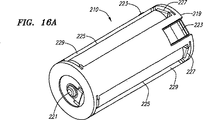
図14を参照すると、懐中電灯200は、光源211の点灯に用いる電力源アセンブリ210を備える。電力源アセンブリ210は、並列に配置された複数の電源用部品を保持するのが好ましい。図16A及び図16Bを参照すると、電力源アセンブリ210は、ハウジング219と、導電片227と、前方接触部221と、放射状接触部223と、例えば、電池225のような電力源とを備える。ハウジング219は、電池225を保持するレセプタクル229を備える。導電片227は、直列回路式又は並列回路式に配置された電池225を電気的に連結するのにハウジング219に選択的に配置される。電池225は、直列回路式に配置して電気的に連結されるのが好ましい。直列回路の端子は、前方接触部221及び放射状接触部223に連結される。
Referring to FIG. 14, the
図14、図16A及び図16Bを参照すると、電力源アセンブリ210は、筒体212の内部に収容される大きさで構成される。前方接触部221は、電力源接触材254と連結する。放射状接触部223は、電力源アセンブリのハウジング219の外周部に配置され、この外周部より外方へ放射状に延在する。このように構成されれば、電力源アセンブリ210が筒体212の内部に収容された場合、放射状接触部223が筒体212と嵌合して電気的に連結する。図示の例では、放射状接触部223が3つ設けられているけれども、本発明は、放射状接触部の数によって限定されるものではない。例えば、電力源アセンブリ210は、放射状接触部を1つ備えているだけでもよい。また、放射状接触部223は、電力源アセンブリ210のほぼ後端に配置された状態で開示されているけれども、放射状接触部223は、電池225と筒体212との電気的接触を確立するために他の位置に配置されてもよい。
Referring to FIGS. 14, 16 </ b> A, and 16 </ b> B, the
電力源アセンブリ210が電池225を筒体212に直接連結するので、端キャップアセンブリ230は、導電用部品として使用されない。したがって、必要に応じて、端キャップ228とバネ材214とを含む端キャップアセンブリ230を、非導電体又は不良導電体で製造してもよい。
Since the
図14及び図15を参照すると、懐中電灯200の電気回路は、ヘッドアセンブリ220を回転することで開閉される。スイッチアセンブリ240が移動して放熱ハウジング244が筒体212のテーパー部227と電気的に連結した場合、電気回路が閉じる。電気回路が一度閉じると、電気エネルギーが、電力源アセンブリ210から電力源接触材254とサーキットアセンブリ250に伝達する。次に、電気エネルギーは、光源211と放熱ハウジング244とを通って、筒体212に流れる。筒体212が、電力源アセンブリ210の放射状接触部223に電気的に連結されることで、電気回路が完成する。このようにして、電気回路が形成され、光源211の点灯に使用される電気エネルギーを供給することができる。
Referring to FIGS. 14 and 15, the electric circuit of the
懐中電灯200の電気回路を開くには、使用者がヘッドアセンブリ220を回転させて、放熱ハウジング244が筒体212のテーパー部227から離れるまで、スイッチアセンブリ240を後方に移動させる。
In order to open the electric circuit of the
上述のように、新規な携帯型の照明部品及び携帯型の照明装置ついて図示及び説明した。本発明の好ましい実施形態を説明しているけれども、多数の変形例、変更例、代替例及び材料の変更は、本発明の属する技術分野の当業者により想到されるものであって、本発明の様々な態様を実現するのに役立てることができる。前記の代替例はすべて、添付の特許請求の範囲に記載された本発明の範囲内にあると考えられる。 As described above, the novel portable illumination component and the portable illumination device have been illustrated and described. While the preferred embodiment of the present invention has been described, numerous variations, modifications, alternatives and material changes will occur to those skilled in the art to which the present invention pertains. It can be used to realize various aspects. All such alternatives are considered to be within the scope of the present invention as set forth in the appended claims.
10,200 懐中電灯
12,212 筒体
14,211 光源
15 電流調整回路
16,225 電池
18 筒体の前方ネジ部
20,220 ヘッドアセンブリ
21 パルス発生器
22 後方ネジ部
23 電源スイッチ
24 縮径領域
25 感温抵抗器
26 前方テーパー部
27 後方テーパー部
28,228 端キャップ
30,230 端キャップアセンブリ
32 導電性バネ
34 外側ネジ領域
35 放射状隆起部
36 シール部材
38 端キャップ用接触材
39 リング部
40,240 スイッチアセンブリ
41 延在片
42,242 上方絶縁体
43 外側延在部
44,244 放熱ハウジング
46 第1接触片
48 第2接触片
50,250 サーキットアセンブリ
52,252 上方導電性バネ
54,254 電力源接触材
56,256 下方絶縁体
58 第1電極
59 第2電極
60,260 スイッチサブアセンブリ
62 サーキットボード
64 接触プラグ
66 第1接触片の可撓性傾斜面
67 第2接触片の可撓性傾斜面
68 第2接触片の連結部材
71 前面部
72 放熱プラグ
74 開口部
75 Oリング
76 放熱ハウジングの内側段部
78 放熱ハウジングの外側テーパー部
79 下方絶縁体のロック用タブ
81 電力源接触材のフランジ
82 スナップ式取付用前方溝
83 挿通孔
84 上方絶縁体のロック用タブ
85 カウンターボアの段部
87 スナップ式取付用後方溝
88 下方絶縁体の後面部
89 下方絶縁体の凹部
91 スナップ式取付用前方溝の段部
92 中央間隙部
93 スナップ式取付用後方溝の段部
94 放物線の焦点
96 上方絶縁体のテーパー部
98 スラグ片
102 フェイスキャップ
104,204 レンズ
106,206 反射器
108 スリーブ
112 スリーブのネジ部
114 反射器の第1端部
116 反射器の第2端部
118 輪郭面
122 反射器の支持部
202 ヘッド部
210 電力源アセンブリ
214 バネ材
216 可撓性タブ
217 ロック用溝
219 電力源アセンブリのハウジング
221 電力源アセンブリの前方接触部
223 電力源アセンブリの放射状接触部
227 筒体のテーパー部
229 電力源アセンブリのレセプタクル
DESCRIPTION OF SYMBOLS 10,200 Flashlight 12,212 Cylinder 14,211 Light source 15 Current adjustment circuit 16,225 Battery 18 Cylinder front screw part 20,220 Head assembly 21 Pulse generator 22 Back screw part 23 Power switch 24 Diameter reduction area 25 Temperature sensitive resistor 26 Front taper portion 27 Rear taper portion 28,228 End cap 30,230 End cap assembly 32 Conductive spring 34 Outer screw region 35 Radial ridge 36 Seal member 38 End cap contact member 39 Ring portion 40,240 Switch assembly 41 Extension piece 42,242 Upper insulator 43 Outer extension portion 44,244 Heat radiation housing 46 First contact piece 48 Second contact piece 50,250 Circuit assembly 52,252 Upper conductive spring 54,254 Power source contact Material 56,256 Lower insulator 8 First electrode 59 Second electrode 60, 260 Switch subassembly 62 Circuit board 64 Contact plug 66 Flexible inclined surface of the first contact piece 67 Flexible inclined surface of the second contact piece 68 Connecting member of the second contact piece 71 Front portion 72 Radiation plug 74 Opening portion 75 O-ring 76 Radial housing inner step 78 Radiation housing outer taper portion 79 Lower insulator locking tab 81 Power source contact material flange 82 Snap-type mounting front groove 83 Insertion Hole 84 Upper insulator locking tab 85 Counter bore step 87 Snap mounting rear groove 88 Lower insulator rear 89 Lower insulator recess 91 Snap mounting front groove 92 Central gap 93 Step part of rear groove for snap-type mounting 94 Focus of parabola 96 Tapered part of upper insulator 98 Slag piece 102 Face cap 104, 204 Lens 106, 206 Reflector 108 Sleeve 112 Sleeve thread 114 Reflector first end 116 Reflector second end 118 Contour surface 122 Reflector support 202 Head part 210 Power source assembly 214 Spring material 216 Flexible tab 217 Locking groove 219 Power source assembly housing 221 Power source assembly front contact 223 Power source assembly radial contact 227 Cylindrical taper 229 Power source assembly receptacle
Claims (26)
電気回路を介して該電力源に連結されるLED光源と、
該LED光源から発する光を反射し、開口第1端部と、第2端部と、該第1端部と該第2端部との間に延在する放物線状輪郭面とを備える反射器と、
前記LED光源の光が前記反射器で反射されるように前記反射器に対して前記LED光源を保持する保持部と、
該放物線状輪郭面の焦点が、前記放物線状輪郭面の外側に位置し、
前記保持部は、電気回路の一部を形成するとともに前記LED光源から熱を伝導させる中空の円柱状に構成された放熱ハウジングを備える、照明装置。A power source,
An LED light source coupled to the power source via an electrical circuit ;
A reflector that reflects light emitted from the LED light source and includes an opening first end, a second end, and a parabolic contour surface extending between the first end and the second end. When,
A holding unit for holding the LED light source with respect to the reflector so that light of the LED light source is reflected by the reflector;
The focal point of the parabolic contour surface is located outside the parabolic contour surface;
The said holding | maintenance part is an illuminating device provided with the thermal radiation housing comprised in the hollow column shape which conducts heat from the said LED light source while forming a part of electric circuit.
前記放物線状輪郭面の頂点から前記第2端部までの距離と前記放物線状輪郭面の頂点から焦点までの距離との比率が、1.5:1以上である、請求項1に記載の照明装置。The opening first end is configured to be larger than the second end;
2. The illumination according to claim 1, wherein a ratio of a distance from the top of the parabolic contour surface to the second end and a distance from the top of the parabolic contour surface to the focal point is 1.5: 1 or more. apparatus.
前記放物線状輪郭面の頂点から前記第2端部までの距離と前記放物線状輪郭面の頂点から焦点までの距離との比率が、6.5:1以下である、請求項1に記載の照明装置。The opening first end is configured to be larger than the second end;
2. The illumination according to claim 1, wherein a ratio of a distance from the top of the parabolic contour surface to the second end and a distance from the top of the parabolic contour surface to the focal point is 6.5: 1 or less. apparatus.
前記放物線状輪郭面の頂点から前記第2端部までの距離と前記放物線状輪郭面の頂点から焦点までの距離との比率が、3.0:1から3.4:1までである、請求項1に記載の照明装置。The opening first end is configured to be larger than the second end;
The ratio of the distance from the vertex of the parabolic contour surface to the second end and the distance from the vertex of the parabolic contour surface to the focal point is from 3.0: 1 to 3.4: 1. Item 2. The lighting device according to Item 1.
前記放物線状輪郭面の頂点から前記第2端部までの距離と前記放物線状輪郭面の頂点から焦点までの距離との比率が、3.2:1である、請求項1に記載の照明装置。The opening first end is configured to be larger than the second end;
2. The lighting device according to claim 1, wherein a ratio of a distance from the top of the parabolic contour surface to the second end and a distance from the top of the parabolic contour surface to the focal point is 3.2: 1. .
前記反射器が、前記ヘッドアセンブリに連結され、
前記主ハウジングが、前記電力源を収容し、
前記主ハウジングに対して前記ヘッドアセンブリを回転することで、前記電力源と前記光源との間の電気回路が開閉する、請求項1に記載の照明装置。A head assembly coupled to the main housing;
The reflector is coupled to the head assembly;
The main housing houses the power source;
The lighting device according to claim 1, wherein an electric circuit between the power source and the light source is opened and closed by rotating the head assembly with respect to the main housing.
前記放熱ハウジングが、前記光源を保持し、前記LED光源を前記主ハウジングに熱伝導可能に連結する、請求項1に記載の照明装置。A main housing,
The lighting device according to claim 1, wherein the heat radiating housing holds the light source and couples the LED light source to the main housing so as to conduct heat.
前記保持部は、前記LED光源から前記主ハウジングに熱を伝導させる、請求項1に記載の照明装置。 Further comprising a main housing forming part of the electrical circuit;
The lighting device according to claim 1, wherein the holding portion conducts heat from the LED light source to the main housing.
前記端キャップが、前記主ハウジングに取り付けられ、
前記主ハウジングが、前記電力源アセンブリを保持し、
前記電力源アセンブリが、前記電力源を保持し、前記電力源を前記主ハウジングに電気的に連結して、前記端キャップを介することなく導電する、請求項1に記載の照明装置。An end cap, a main housing, and a power source assembly, wherein the end cap is attached to the main housing;
The main housing holds the power source assembly;
The lighting device of claim 1, wherein the power source assembly holds the power source and electrically couples the power source to the main housing to conduct without going through the end cap.
180°以下の球面角度で略放射状に光を照射し、前記携帯型電力源に連結されるLEDランプと、
該LEDランプで照射した光を反射して高輝質のビーム光を作り出し、開口第1端部と、開口第2端部と、前記2つの端部の間を延在する軸部とを備える放物線状反射器と、
前記LEDランプの光が前記反射器で反射されるように前記反射器に対して前記LEDランプを保持する保持部と
を備え、
前記放物線状反射器の焦点が、前記開口第1端部と前記開口第2端部との間に位置せず、
前記焦点の長さが、0.020インチから0.050インチまでであり、
前記開口第1端部の直径が、前記開口第2端部の直径より大きく、
前記開口第1端部が、0.70インチから0.80インチまでの直径で構成され、
前記保持部は、電気回路の一部を形成するとともに前記LEDランプから熱を伝導させる中空の円柱状に構成された放熱ハウジングを備える、懐中電灯。A portable power source;
An LED lamp that emits light substantially radially at a spherical angle of 180 ° or less, and is connected to the portable power source;
A parabola that reflects light emitted from the LED lamp to produce high-quality beam light, and includes a first end portion of the opening, a second end portion of the opening, and a shaft portion extending between the two end portions. A reflector ,
A holding unit for holding the LED lamp with respect to the reflector so that the light of the LED lamp is reflected by the reflector ;
The focal point of the parabolic reflector is not located between the opening first end and the opening second end;
The focal length is from 0.020 inch to 0.050 inch;
A diameter of the opening first end is larger than a diameter of the opening second end;
The opening first end is configured with a diameter from 0.70 inches to 0.80 inches;
The said holding | maintenance part is a flashlight provided with the thermal radiation housing comprised in the hollow column shape which conducts heat from the said LED lamp while forming a part of electric circuit.
該携帯型電力源に連結され、LEDとレンズとを備える光源と、
該光源から照射した光を反射して高輝質のビーム光を作り出す移動可能な放物線状反射器と、
前記光源の光が移動可能な前記反射器で反射されるように前記反射器に対して前記光源を保持する保持部と
を備え、
前記レンズが、前記LEDの位置に対して180°以下の角度で前記光源から光を実質的に照射するように、LED上に配置され、
前記放物線状反射器が、開口第1端部と、開口第2端部と、該開口第1端部と該開口第2端部との間を延在する放物線状輪郭面とを備え、
放物線形の焦点が、該放物線状輪郭面の外側に位置し、
前記放物線形の焦点の長さが、0.020インチから0.050インチまでであり、
前記開口第1端部の直径が、前記開口第2端部の直径より大きく、
前記放物線状輪郭面の頂点から前記開口第2端部までの距離と前記放物線状輪郭面の頂点から焦点までの距離との比率が、3:1以上であり、
前記保持部は、電気回路の一部を形成するとともに前記光源から熱を伝導させる中空の円柱状に構成された放熱ハウジングを備える、懐中電灯。A portable power source;
A light source coupled to the portable power source and comprising an LED and a lens;
A movable parabolic reflector that reflects light emitted from the light source to produce high-quality beam light ;
A holding unit for holding the light source with respect to the reflector so that the light of the light source is reflected by the movable reflector,
The lens is disposed on the LED such that the lens substantially emits light from the light source at an angle of 180 ° or less relative to the position of the LED;
The parabolic reflector includes an opening first end, an opening second end, and a parabolic contour surface extending between the opening first end and the opening second end,
The parabolic focus is located outside the parabolic contour surface;
The parabolic focus length is from 0.020 inch to 0.050 inch;
A diameter of the opening first end is larger than a diameter of the opening second end;
The ratio of the distance from the apex of the parabolic contour surface to the opening second end and the distance from the apex of the parabolic contour surface to the focal point is 3: 1 or more,
The said holding | maintenance part is a flashlight provided with the thermal radiation housing comprised in the hollow column shape which conducts heat from the said light source while forming a part of electric circuit.
電気回路を介して該電力源に連結されるLED光源と、
該LED光源から照射した光を反射し、開口第1端部と、開口第2端部と、該開口第1端部と該開口第2端部との間を延在する放物線状輪郭面とを備える反射器と、
前記LED光源の光が前記反射器で反射されるように前記反射器に対して前記LED光源を保持する保持部と、
サーキットアセンブリとを備え、
前記開口第1端部が、ビーム光を放つように構成され、
前記放物線状輪郭面の焦点が、前記開口第1端部と前記開口第2端部との間に位置せず、
前記保持部は、電気回路の一部を形成するとともに前記LED光源から熱を伝導させる中空の円柱状に構成された放熱ハウジングを備え、
前記サーキットアセンブリは、前記放熱ハウジングの中空の円柱内に配置され、前記LED光源に流れる電気を制御する、懐中電灯。A power source,
An LED light source coupled to the power source via an electrical circuit;
Reflecting light emitted from the LED light source, a first end portion of the opening, a second end portion of the opening, and a parabolic contour surface extending between the first end portion of the opening and the second end portion of the opening A reflector comprising:
A holding unit for holding the LED light source with respect to the reflector so that light of the LED light source is reflected by the reflector;
With circuit assembly,
The opening first end is configured to emit beam light;
The focal point of the parabolic contour surface is not located between the opening first end and the opening second end,
The holding portion includes a heat radiating housing configured in a hollow cylindrical shape that forms part of an electric circuit and conducts heat from the LED light source,
The circuit assembly is a flashlight that is disposed in a hollow cylinder of the heat dissipation housing and controls electricity flowing to the LED light source.
前記保持部は、前記LED光源から前記主ハウジングに熱を伝導させる、請求項20に記載の懐中電灯。A main housing for accommodating the power source;
21. The flashlight according to claim 20, wherein the holding part conducts heat from the LED light source to the main housing.
Applications Claiming Priority (3)
| Application Number | Priority Date | Filing Date | Title |
|---|---|---|---|
| US10/922,714 | 2004-08-20 | ||
| US10/922,714 US8733966B2 (en) | 2004-08-20 | 2004-08-20 | LED flashlight |
| PCT/US2005/028560 WO2006023362A2 (en) | 2004-08-20 | 2005-08-10 | Improved led flashlight |
Publications (3)
| Publication Number | Publication Date |
|---|---|
| JP2008511101A JP2008511101A (en) | 2008-04-10 |
| JP2008511101A5 JP2008511101A5 (en) | 2008-09-25 |
| JP5000511B2 true JP5000511B2 (en) | 2012-08-15 |
Family
ID=35909397
Family Applications (1)
| Application Number | Title | Priority Date | Filing Date |
|---|---|---|---|
| JP2007527879A Expired - Fee Related JP5000511B2 (en) | 2004-08-20 | 2005-08-10 | Improved LED flashlight |
Country Status (17)
| Country | Link |
|---|---|
| US (4) | US8733966B2 (en) |
| EP (1) | EP1834128A2 (en) |
| JP (1) | JP5000511B2 (en) |
| KR (2) | KR101340256B1 (en) |
| CN (4) | CN101676597B (en) |
| AU (1) | AU2005277692A1 (en) |
| BR (1) | BRPI0514517A (en) |
| CA (1) | CA2577337A1 (en) |
| CR (1) | CR8979A (en) |
| EA (4) | EA012771B1 (en) |
| MX (1) | MX2007001939A (en) |
| MY (1) | MY147901A (en) |
| NO (1) | NO20071225L (en) |
| NZ (2) | NZ553568A (en) |
| TW (1) | TW200613680A (en) |
| WO (1) | WO2006023362A2 (en) |
| ZA (1) | ZA200701911B (en) |
Families Citing this family (73)
| Publication number | Priority date | Publication date | Assignee | Title |
|---|---|---|---|---|
| US6722772B2 (en) * | 2001-08-16 | 2004-04-20 | Mag Instrument, Inc. | Flashlight and combination for use in aligning flashlight lamp bulbs |
| TWM266402U (en) * | 2004-08-03 | 2005-06-01 | Kingwell Products Inc | Improved structure of electric torch |
| US8733966B2 (en) | 2004-08-20 | 2014-05-27 | Mag Instrument, Inc. | LED flashlight |
| US7986112B2 (en) * | 2005-09-15 | 2011-07-26 | Mag Instrument, Inc. | Thermally self-stabilizing LED module |
| US7357534B2 (en) * | 2006-03-31 | 2008-04-15 | Streamlight, Inc. | Flashlight providing thermal protection for electronic elements thereof |
| WO2007145708A2 (en) * | 2006-04-19 | 2007-12-21 | Underwater Kinetics, Llp | Methods and devices that employ thermal control of current to electrical components |
| US7614766B2 (en) * | 2006-06-29 | 2009-11-10 | Harvatek Corporation | Modular illumination device with adjustable lighting angles |
| US7883243B2 (en) | 2006-07-20 | 2011-02-08 | Streamlight, Inc. | LED flashlight and heat sink arrangement |
| US7633037B2 (en) * | 2006-12-19 | 2009-12-15 | Eveready Battery Co., Inc. | Positive temperature coefficient light emitting diode light |
| US20080198604A1 (en) * | 2007-02-20 | 2008-08-21 | Sekonix Co., Ltd. | Lighting apparatus using filter and condenser for led illumination |
| US7860480B2 (en) * | 2007-06-29 | 2010-12-28 | Silicon Laboratories Inc. | Method and apparatus for controlling a harmonic rejection mixer |
| US7863821B1 (en) | 2007-08-06 | 2011-01-04 | Gene Malkoff | Drop-in light emitting diode (LED) module, reflector, and flashlight including same |
| US7633229B1 (en) | 2007-08-06 | 2009-12-15 | Gene Malkoff | Drop-in light emitting diode (LED) module, reflector, and flashlight including same |
| US20090129064A1 (en) * | 2007-11-15 | 2009-05-21 | Zeller Noel E | Convertible flashlight/headlight |
| TW200947057A (en) * | 2008-05-06 | 2009-11-16 | Advanced Optoelectronic Tech | Light module for LCD backlight module |
| USD595440S1 (en) | 2008-06-20 | 2009-06-30 | Leatherman Tool Group, Inc. | Flashlight |
| US7758205B2 (en) * | 2008-08-05 | 2010-07-20 | Yun-Zhao Liu | Flashlight |
| US9022612B2 (en) * | 2008-08-07 | 2015-05-05 | Mag Instrument, Inc. | LED module |
| US8134300B2 (en) * | 2008-08-08 | 2012-03-13 | Mag Instrument, Inc. | Portable lighting devices |
| IT1399275B1 (en) * | 2008-09-15 | 2013-04-11 | Fasangas S R L | PORTABLE LAMP WITH HIGH VERSATILITY |
| USD601287S1 (en) | 2009-01-14 | 2009-09-29 | Leatherman Tool Group, Inc. | Flashlight |
| USD637748S1 (en) | 2009-01-14 | 2011-05-10 | Leatherman Tool Group, Inc. | Flashlight |
| US9247598B2 (en) * | 2009-01-16 | 2016-01-26 | Mag Instrument, Inc. | Portable lighting devices |
| US8356910B2 (en) * | 2009-04-22 | 2013-01-22 | Streamlight, Inc. | Rechargeable flashlight, battery and charger adapter and protector therefor |
| CN101872849B (en) * | 2009-04-27 | 2013-11-06 | 鸿富锦精密工业(深圳)有限公司 | Battery box and electronic device adopting same |
| USD643561S1 (en) | 2009-07-13 | 2011-08-16 | Mag Instrument, Inc. | Flashlight |
| JP4866953B2 (en) * | 2009-10-09 | 2012-02-01 | 廣東正飛移動照明有限公司 | flashlight |
| US9200792B2 (en) | 2009-11-24 | 2015-12-01 | Streamlight, Inc. | Portable light having a heat dissipater with an integral cooling device |
| CN105282892A (en) * | 2010-05-04 | 2016-01-27 | 吉可多公司 | LED lighting apparatus with communication port for sending related information |
| CN101886783A (en) * | 2010-06-30 | 2010-11-17 | 海洋王照明科技股份有限公司 | Spot lamp reflector, spot lamp and head lamp |
| EP2589265A1 (en) * | 2010-06-30 | 2013-05-08 | Koninklijke Philips Electronics N.V. | Dimmable lighting device |
| US8459844B2 (en) | 2010-07-01 | 2013-06-11 | Welch Allyn, Inc. | Replacement light assembly |
| USD640400S1 (en) * | 2010-10-22 | 2011-06-21 | Chia-Ling Huang | Portable lighting device |
| USD681858S1 (en) | 2011-01-10 | 2013-05-07 | Streamlight, Inc. | Portable light |
| US9453624B2 (en) | 2011-01-13 | 2016-09-27 | Streamlight, Inc. | Portable light with light source module and light source module |
| US8905573B2 (en) | 2011-01-13 | 2014-12-09 | Streamlight, Inc. | Portable light with hanger, clip and led module |
| DE202011109155U1 (en) * | 2011-05-25 | 2012-08-30 | Zweibrüder Optoelectronics Gmbh & Co. Kg | Focusable flashlight |
| CN202253393U (en) * | 2011-07-25 | 2012-05-30 | 阳西星际科技有限公司 | Improved optical stack and electric torch employing same |
| KR101911762B1 (en) | 2011-08-09 | 2018-10-26 | 엘지이노텍 주식회사 | Lighting device |
| DE102012106293A1 (en) * | 2012-07-12 | 2014-01-16 | Hella Kgaa Hueck & Co. | Locking system for closing an opening of a vehicle lamp and vehicle lamp |
| PE20150544A1 (en) * | 2012-08-10 | 2015-05-06 | Vioptix Inc | TISSUE OXIMETRY DEVICE, MANUAL, WIRELESS |
| DE102013000153A1 (en) * | 2013-01-04 | 2014-07-10 | Zweibrüder Optoelectronics Gmbh & Co. Kg | Flashlight with a rotary switch |
| US9488361B2 (en) * | 2013-01-13 | 2016-11-08 | Mag Instrument, Inc. | Lighting devices |
| WO2014110533A2 (en) | 2013-01-13 | 2014-07-17 | Mag Instrument, Inc. | Improved lighting devices |
| US9494285B2 (en) | 2013-01-13 | 2016-11-15 | Mag Instrument, Inc | Lighting devices |
| US9239161B2 (en) * | 2013-05-07 | 2016-01-19 | Surefire Llc. | Coupling for a sealed, lockable battery pack and power adapter and a high intensity search light |
| CN103557438B (en) * | 2013-10-25 | 2016-03-16 | 大连恭德科技有限公司 | A kind of multistage push type LED |
| US9255673B2 (en) | 2013-12-27 | 2016-02-09 | Switch Bulb Company, Inc. | LED bulb having an adjustable light-distribution profile |
| USD743601S1 (en) * | 2014-02-04 | 2015-11-17 | Mag Instrument, Inc. | Flashlight |
| US9671085B2 (en) | 2014-04-22 | 2017-06-06 | Dow Corning Corporation | Reflector for an LED light source |
| CN103994337A (en) * | 2014-05-27 | 2014-08-20 | 西安精英光电技术有限公司 | LED strong-light flashlight with laser pointer |
| EP3238278B1 (en) | 2014-12-22 | 2020-03-04 | MAG Instrument, Inc. | Improved efficiency lighting apparatus with led directly mounted to a heatsink |
| US10001260B2 (en) * | 2015-02-19 | 2018-06-19 | Bradley W. Hoover | Flashlight device for observing objects in a conduit |
| CN104676275B (en) * | 2015-03-05 | 2018-08-24 | 宁波福泰电器有限公司 | Gravity sensing flashlight and control circuit |
| US10212994B2 (en) | 2015-11-02 | 2019-02-26 | Icon Health & Fitness, Inc. | Smart watch band |
| DE102015223362A1 (en) * | 2015-11-25 | 2017-06-01 | Minimax Gmbh & Co. Kg | Explosion-proof housing for means for transmitting and receiving electromagnetic radiation |
| US10820428B2 (en) * | 2017-06-28 | 2020-10-27 | The Boeing Company | Attachment apparatus and methods for use |
| US10228110B1 (en) * | 2018-04-09 | 2019-03-12 | Robert Evans | Handheld illunating device with orb-shaped lens for enhancing forward and lateral visibility |
| CA3121315C (en) * | 2018-11-27 | 2025-03-11 | West Coast Imports, Inc. | Rotating light |
| USD899656S1 (en) | 2018-12-28 | 2020-10-20 | West Coast Imports, Inc. | Circular light |
| USD909646S1 (en) | 2018-11-27 | 2021-02-02 | West Coast Imports, Inc. | Circular light |
| JP2020123449A (en) * | 2019-01-29 | 2020-08-13 | パナソニックIpマネジメント株式会社 | Portable light |
| US11428390B2 (en) | 2019-02-12 | 2022-08-30 | West Coast Imports, Inc. | Rotating light |
| US11598517B2 (en) | 2019-12-31 | 2023-03-07 | Lumien Enterprise, Inc. | Electronic module group |
| US12281783B2 (en) | 2019-12-31 | 2025-04-22 | Lumien Enterprise, Inc. | Electronic module group |
| CN110985903B (en) | 2019-12-31 | 2020-08-14 | 江苏舒适照明有限公司 | Lamp module |
| WO2021142461A1 (en) | 2020-01-10 | 2021-07-15 | Vioptix, Inc. | Near-field communication security for medical device and sheath |
| EP4087479A4 (en) | 2020-01-10 | 2024-11-27 | Vioptix, Inc. | PRODUCTION OF MEASUREMENT MEASURES IN A MEDICAL DEVICE |
| US11672448B2 (en) | 2020-01-10 | 2023-06-13 | Vioptix, Inc. | Probe tip for medical device |
| US12357204B2 (en) | 2020-01-10 | 2025-07-15 | Vioptix, Inc. | Medical device and sheath seal and seal verification |
| CN111503556B (en) | 2020-04-23 | 2020-11-27 | 江苏舒适照明有限公司 | a spotlight structure |
| US12230950B2 (en) | 2021-07-29 | 2025-02-18 | Lumien Enterprise, Inc. | Junction box |
| FR3164425A1 (en) * | 2024-07-15 | 2026-01-16 | Valeo Vision | A motor vehicle's lighting system comprising a light beam emission module and a temperature sensor |
Family Cites Families (117)
| Publication number | Priority date | Publication date | Assignee | Title |
|---|---|---|---|---|
| SU402095A1 (en) | 1972-04-17 | 1973-10-12 | CASE FOR PRIMARY BATTERY | |
| US4080571A (en) * | 1976-06-03 | 1978-03-21 | Rca Corporation | Apparatus for measuring the current-voltage characteristics of a TRAPATT diode |
| US4286311A (en) | 1978-04-07 | 1981-08-25 | Anthony Maglica | Flashlight |
| US5349506A (en) | 1984-09-06 | 1994-09-20 | Mag Instrument, Inc. | Miniature flashlight |
| US4823242A (en) | 1984-09-06 | 1989-04-18 | Mag Instrument, Inc. | Double switch miniature flashlight |
| US4851974A (en) | 1984-09-06 | 1989-07-25 | Mag Instrument, Inc. | Flashlight |
| US4656565A (en) | 1984-09-06 | 1987-04-07 | Mag Instrument, Inc. | Flashlight |
| JPS61105897A (en) | 1984-10-30 | 1986-05-23 | キヤノン株式会社 | Electronics |
| US4647139A (en) | 1985-07-31 | 1987-03-03 | Yang Tai Her | Extention cord charging device for connecting tools and appliances to plug receptacle in vehicle |
| US4675259A (en) * | 1986-02-25 | 1987-06-23 | Halliburton Company | Electrical energy package and method of assembly |
| US4722036A (en) * | 1987-02-12 | 1988-01-26 | Eveready Battery Company | Flashlight |
| US5459649A (en) * | 1991-04-10 | 1995-10-17 | Ellion; M. Edmund | Flashlight with an enhanced spot beam and a fully illuminated broad beam |
| US5213408A (en) * | 1992-06-01 | 1993-05-25 | Shiau Shoei Shuh | Variable focusing flashlight |
| JP2566195Y2 (en) | 1992-07-17 | 1998-03-25 | 富士電気化学株式会社 | Portable light |
| NL9300971A (en) | 1993-06-04 | 1995-01-02 | Framatome Connectors Belgium | Circuit board connector assembly. |
| US6835898B2 (en) | 1993-11-16 | 2004-12-28 | Formfactor, Inc. | Electrical contact structures formed by configuring a flexible wire to have a springable shape and overcoating the wire with at least one layer of a resilient conductive material, methods of mounting the contact structures to electronic components, and applications for employing the contact structures |
| JPH07262810A (en) * | 1994-03-18 | 1995-10-13 | Sony Tektronix Corp | Light emitting device |
| US5678921A (en) * | 1994-12-06 | 1997-10-21 | Bright Star Industries, Inc. | Flashlight |
| JPH08212825A (en) | 1995-02-08 | 1996-08-20 | Olympus Optical Co Ltd | Halogen lamp device |
| US6406196B1 (en) | 1995-08-03 | 2002-06-18 | Matsushita Electric Industrial Co., Ltd. | Optical device and method for producing the same |
| US5765937A (en) * | 1995-11-27 | 1998-06-16 | Shiau; Shoei-Shuh | Multi-function lighting device |
| CN1155050A (en) * | 1996-10-29 | 1997-07-23 | 家电宝实业有限公司 | Fireproof floor halogen lamp |
| US5783909A (en) | 1997-01-10 | 1998-07-21 | Relume Corporation | Maintaining LED luminous intensity |
| US5871272A (en) * | 1997-01-28 | 1999-02-16 | Streamlight, Incorporated | Flashlight with rotatable lamp head |
| US5865529A (en) | 1997-03-10 | 1999-02-02 | Yan; Ellis | Light emitting diode lamp having a spherical radiating pattern |
| US5904414A (en) * | 1997-03-21 | 1999-05-18 | Underwater Kinetics | Flashlight with gas permeable membrane and battery polarization |
| US5975714A (en) | 1997-06-03 | 1999-11-02 | Applied Innovative Technologies, Incorporated | Renewable energy flashlight |
| US6046572A (en) | 1997-12-05 | 2000-04-04 | Laser Products Ltd. | Battery operated appliance, flashlight and switching systems |
| JPH11176405A (en) | 1997-12-10 | 1999-07-02 | Nikon Corp | Equipment using battery pack |
| US6220719B1 (en) | 1998-02-11 | 2001-04-24 | Applied Innovative Technologies, Inc. | Renewable energy flashlight |
| US6152590A (en) | 1998-02-13 | 2000-11-28 | Donnelly Hohe Gmbh & Co. Kg | Lighting device for motor vehicles |
| DE19810827A1 (en) * | 1998-03-12 | 1999-09-16 | Siemens Ag | Circuit for temperature dependent current supply to LED |
| US6095661A (en) * | 1998-03-19 | 2000-08-01 | Ppt Vision, Inc. | Method and apparatus for an L.E.D. flashlight |
| US5974064A (en) | 1998-04-14 | 1999-10-26 | Optobahn Corporation | Temperature compensation of laser diodes |
| US6186634B1 (en) * | 1998-06-25 | 2001-02-13 | Algerome Pitts | Ever brite ready light |
| US6693556B1 (en) * | 1998-07-13 | 2004-02-17 | Blinkerstop Llc | Enhanced visibility traffic signal |
| US6127784A (en) | 1998-08-31 | 2000-10-03 | Dialight Corporation | LED driving circuitry with variable load to control output light intensity of an LED |
| US6249089B1 (en) | 1998-10-09 | 2001-06-19 | Frederick Bruwer | Intelligent electrical device comprising microchip |
| US6086218A (en) | 1998-10-23 | 2000-07-11 | Cal June Inc. | Portable flashing signal light |
| US6274924B1 (en) | 1998-11-05 | 2001-08-14 | Lumileds Lighting, U.S. Llc | Surface mountable LED package |
| US6099147A (en) * | 1998-11-19 | 2000-08-08 | Streamlight, Inc. | Flashlight lamp shock absorber |
| US6345464B1 (en) | 1999-01-13 | 2002-02-12 | Surefire, Llc | Firearms with target illuminators, electric switching devices and battery power sources |
| JP3656805B2 (en) | 1999-01-22 | 2005-06-08 | パイオニア株式会社 | Organic EL element driving device having temperature compensation function |
| US6190020B1 (en) | 1999-06-23 | 2001-02-20 | Fred Jack Hartley | Light producing assembly for a flashlight |
| DE19930174A1 (en) * | 1999-06-30 | 2001-01-04 | Patent Treuhand Ges Fuer Elektrische Gluehlampen Mbh | Control circuit for LED and associated operating method |
| IT1308779B1 (en) | 1999-07-02 | 2002-01-10 | Elasis Sistema Ricerca Fiat | DEVICE FOR ADJUSTING THE DELIVERY PRESSURE OF A PUMP, SUITABLE FOR FUEL SUPPLY TO A COMBUSTION ENGINE |
| US6153985A (en) | 1999-07-09 | 2000-11-28 | Dialight Corporation | LED driving circuitry with light intensity feedback to control output light intensity of an LED |
| US6220720B1 (en) * | 1999-07-16 | 2001-04-24 | Princeton Tectonics, Inc. | Flashlight |
| US6168288B1 (en) | 1999-08-05 | 2001-01-02 | Tektite Industries West Llc | Flashlight with light emitting diodes |
| US6712486B1 (en) | 1999-10-19 | 2004-03-30 | Permlight Products, Inc. | Mounting arrangement for light emitting diodes |
| KR100421688B1 (en) | 1999-11-11 | 2004-03-10 | 도요다 고세이 가부시키가이샤 | Full-color Light Source Unit |
| US6161910A (en) | 1999-12-14 | 2000-12-19 | Aerospace Lighting Corporation | LED reading light |
| AU2001229632A1 (en) | 2000-01-14 | 2001-07-24 | Design Rite Llc | Circuit for driving light-emitting diodes |
| US6328456B1 (en) | 2000-03-24 | 2001-12-11 | Ledcorp | Illuminating apparatus and light emitting diode |
| JP2001326569A (en) | 2000-05-16 | 2001-11-22 | Toshiba Corp | LED drive circuit and optical transmission module |
| US6585391B1 (en) | 2000-05-31 | 2003-07-01 | Nordic Technologies, Inc. | Flashlight and flashlight electrical connectors |
| US6439738B1 (en) | 2000-08-02 | 2002-08-27 | Surefire, Llc | Battery powered portable electric light source systems |
| JP2002075027A (en) | 2000-09-01 | 2002-03-15 | Ichikoh Ind Ltd | Vehicle lighting |
| AU2002224490A1 (en) | 2000-11-09 | 2002-05-21 | Azoteq (Pty) Ltd. | Light emitting device |
| US6441558B1 (en) | 2000-12-07 | 2002-08-27 | Koninklijke Philips Electronics N.V. | White LED luminary light control system |
| CN2457439Y (en) * | 2000-12-18 | 2001-10-31 | 周晓刚 | Flashlight capable of focusing light |
| US6411046B1 (en) | 2000-12-27 | 2002-06-25 | Koninklijke Philips Electronics, N. V. | Effective modeling of CIE xy coordinates for a plurality of LEDs for white LED light control |
| US6622416B2 (en) | 2001-01-04 | 2003-09-23 | Surefire, Llc | Target and navigation illuminators for firearms |
| US6717559B2 (en) | 2001-01-16 | 2004-04-06 | Visteon Global Technologies, Inc. | Temperature compensated parallel LED drive circuit |
| US6517215B2 (en) | 2001-01-18 | 2003-02-11 | Tektite Industries Inc. | Flashlight with off set light source |
| US6623140B2 (en) * | 2001-04-13 | 2003-09-23 | Scott R. Watterson | Illumination device having multiple light sources |
| JP2002324685A (en) | 2001-04-25 | 2002-11-08 | Sony Corp | Lighting equipment |
| CN2491693Y (en) | 2001-05-23 | 2002-05-15 | 戴展传 | Power Saving High Brightness Pocket Flashlight |
| DE10134246A1 (en) * | 2001-07-18 | 2003-02-06 | Patent Treuhand Ges Fuer Elektrische Gluehlampen Mbh | Control gear for LEDs with temperature-dependent current control |
| US6722772B2 (en) | 2001-08-16 | 2004-04-20 | Mag Instrument, Inc. | Flashlight and combination for use in aligning flashlight lamp bulbs |
| GB2369730B (en) * | 2001-08-30 | 2002-11-13 | Integrated Syst Tech Ltd | Illumination control system |
| US6791283B2 (en) | 2001-09-07 | 2004-09-14 | Opalec | Dual mode regulated light-emitting diode module for flashlights |
| CN1240102C (en) | 2001-10-31 | 2006-02-01 | 东芝照明技术株式会社 | Bulb shape flurescent lamp and lighting device |
| US6827468B2 (en) | 2001-12-10 | 2004-12-07 | Robert D. Galli | LED lighting assembly |
| US6966677B2 (en) * | 2001-12-10 | 2005-11-22 | Galli Robert D | LED lighting assembly with improved heat management |
| US6974234B2 (en) | 2001-12-10 | 2005-12-13 | Galli Robert D | LED lighting assembly |
| US6693394B1 (en) * | 2002-01-25 | 2004-02-17 | Yazaki North America, Inc. | Brightness compensation for LED lighting based on ambient temperature |
| US6880951B2 (en) | 2002-04-04 | 2005-04-19 | Altec Co., Ltd. | Flashlight using a light emitting diode as a lamp |
| JP2003331601A (en) | 2002-04-04 | 2003-11-21 | Aitec Co Ltd | Light emitting diode flash light |
| US6789917B2 (en) * | 2002-05-06 | 2004-09-14 | Armament Systems And Procedures, Inc. | Dual mode rechargeable flashlight |
| US6841947B2 (en) * | 2002-05-14 | 2005-01-11 | Garmin At, Inc. | Systems and methods for controlling brightness of an avionics display |
| US6808267B2 (en) * | 2002-10-18 | 2004-10-26 | Childsplay Vision Systems | Method for automated mass screening for visual dysfunction in children |
| US7153004B2 (en) | 2002-12-10 | 2006-12-26 | Galli Robert D | Flashlight housing |
| JP4286528B2 (en) | 2002-12-13 | 2009-07-01 | パナソニック株式会社 | LED lighting device |
| JP4299006B2 (en) | 2003-01-08 | 2009-07-22 | パナソニック株式会社 | Portable LED lighting device |
| US7116061B2 (en) | 2003-01-16 | 2006-10-03 | Surefire, Llc | Brightness controllable flashlights |
| US6841941B2 (en) | 2003-01-16 | 2005-01-11 | Surefire, Llc | Brightness controllable flashlights |
| US6854865B2 (en) | 2003-02-12 | 2005-02-15 | W. T. Storey, Inc. | Reflector for light emitting objects |
| US20040190286A1 (en) * | 2003-03-25 | 2004-09-30 | Chapman Leonard T. | Flashlight |
| US7543961B2 (en) | 2003-03-31 | 2009-06-09 | Lumination Llc | LED light with active cooling |
| US7091874B2 (en) * | 2003-04-18 | 2006-08-15 | Smithson Bradley D | Temperature compensated warning light |
| RU32744U1 (en) | 2003-05-19 | 2003-09-27 | ООО Научно-производственный центр "Экспресс" | Signal light for a passenger car |
| US7344268B2 (en) * | 2003-07-07 | 2008-03-18 | Xenonics, Inc. | Long-range, handheld illumination system |
| JP2005031430A (en) | 2003-07-14 | 2005-02-03 | Tohoku Pioneer Corp | Method and device for driving light emitting display panel |
| US20050047161A1 (en) * | 2003-08-26 | 2005-03-03 | Mei-Hui Tai | Centrifugal force-activated signal light assembly for vehicles |
| US7318661B2 (en) * | 2003-09-12 | 2008-01-15 | Anthony Catalano | Universal light emitting illumination device and method |
| US7296913B2 (en) * | 2004-07-16 | 2007-11-20 | Technology Assessment Group | Light emitting diode replacement lamp |
| US6942359B2 (en) * | 2003-12-08 | 2005-09-13 | Eveready Battery Company, Inc. | Flashlight that can operate with alternative size batteries |
| US7293893B2 (en) | 2003-12-09 | 2007-11-13 | Surefire Llc | Flashlight with adjustable color selector switch |
| US7083297B2 (en) | 2003-12-09 | 2006-08-01 | Surefire Llc | Flashlight with lens for transmitting central and off-axis light sources |
| US7344270B2 (en) * | 2003-12-09 | 2008-03-18 | Surefire, Llc | Flashlight with incrementing brightness selector switch |
| US7186002B2 (en) * | 2003-12-09 | 2007-03-06 | Surefire Llc | Flashlight with selectable output level switching |
| US7220016B2 (en) | 2003-12-09 | 2007-05-22 | Surefire, Llc | Flashlight with selectable output level switching |
| US7014335B2 (en) * | 2004-03-03 | 2006-03-21 | W.T. Storey, Inc. | Flashlight with wave spring electrical connection |
| US7215086B2 (en) * | 2004-04-23 | 2007-05-08 | Lighting Science Group Corporation | Electronic light generating element light bulb |
| US7138659B2 (en) | 2004-05-18 | 2006-11-21 | Onscreen Technologies, Inc. | LED assembly with vented circuit board |
| US8733966B2 (en) | 2004-08-20 | 2014-05-27 | Mag Instrument, Inc. | LED flashlight |
| US20060132323A1 (en) | 2004-09-27 | 2006-06-22 | Milex Technologies, Inc. | Strobe beacon |
| US7579782B2 (en) | 2004-12-07 | 2009-08-25 | Mag Instrument, Inc. | Circuitry for portable lighting devices and portable rechargeable electronic devices |
| US7457132B2 (en) | 2005-10-20 | 2008-11-25 | Sanmina-Sci Corporation | Via stub termination structures and methods for making same |
| CA2565644C (en) | 2005-10-26 | 2014-05-20 | Pentair Water Pool And Spa, Inc. | Led pool and spa light |
| US7736044B2 (en) | 2006-05-26 | 2010-06-15 | Avago Technologies General Ip (Singapore) Pte. Ltd. | Indirect lighting device for light guide illumination |
| US7441920B2 (en) | 2006-07-13 | 2008-10-28 | Pelican Products, Inc. | Multi-switch flashlight |
| US7808013B2 (en) | 2006-10-31 | 2010-10-05 | Cree, Inc. | Integrated heat spreaders for light emitting devices (LEDs) and related assemblies |
| CN101210664A (en) | 2006-12-29 | 2008-07-02 | 富准精密工业(深圳)有限公司 | Light-emitting diode lamps and lanterns |
| US7549765B2 (en) | 2007-01-30 | 2009-06-23 | Surefire, Llc | Flashlight with multistage switch and ARC lamp operation sensor |
| US7976182B2 (en) | 2007-03-21 | 2011-07-12 | International Rectifier Corporation | LED lamp assembly with temperature control and method of making the same |
-
2004
- 2004-08-20 US US10/922,714 patent/US8733966B2/en not_active Expired - Lifetime
-
2005
- 2005-07-07 MY MYPI20053112A patent/MY147901A/en unknown
- 2005-07-12 TW TW094123626A patent/TW200613680A/en unknown
- 2005-08-10 CN CN2009101735625A patent/CN101676597B/en not_active Expired - Fee Related
- 2005-08-10 KR KR1020127031485A patent/KR101340256B1/en not_active Expired - Fee Related
- 2005-08-10 JP JP2007527879A patent/JP5000511B2/en not_active Expired - Fee Related
- 2005-08-10 WO PCT/US2005/028560 patent/WO2006023362A2/en not_active Ceased
- 2005-08-10 EP EP05786317A patent/EP1834128A2/en not_active Withdrawn
- 2005-08-10 CN CN200910173560A patent/CN101676596A/en active Pending
- 2005-08-10 AU AU2005277692A patent/AU2005277692A1/en not_active Abandoned
- 2005-08-10 CN CNA2005800335860A patent/CN101305240A/en active Pending
- 2005-08-10 CA CA002577337A patent/CA2577337A1/en not_active Abandoned
- 2005-08-10 EA EA200801486A patent/EA012771B1/en not_active IP Right Cessation
- 2005-08-10 KR KR1020077006204A patent/KR101292942B1/en not_active Expired - Fee Related
- 2005-08-10 NZ NZ553568A patent/NZ553568A/en not_active IP Right Cessation
- 2005-08-10 EA EA200801485A patent/EA200801485A1/en unknown
- 2005-08-10 EA EA200700468A patent/EA012484B1/en not_active IP Right Cessation
- 2005-08-10 CN CN2009101735610A patent/CN101677123B/en not_active Expired - Fee Related
- 2005-08-10 MX MX2007001939A patent/MX2007001939A/en active IP Right Grant
- 2005-08-10 ZA ZA200701911A patent/ZA200701911B/en unknown
- 2005-08-10 BR BRPI0514517-1A patent/BRPI0514517A/en not_active IP Right Cessation
- 2005-08-10 EA EA200801487A patent/EA200801487A1/en unknown
- 2005-08-10 NZ NZ589364A patent/NZ589364A/en not_active IP Right Cessation
-
2007
- 2007-03-06 NO NO20071225A patent/NO20071225L/en not_active Application Discontinuation
- 2007-03-07 CR CR8979A patent/CR8979A/en not_active Application Discontinuation
-
2014
- 2014-05-26 US US14/287,176 patent/US9719658B2/en not_active Expired - Fee Related
-
2017
- 2017-06-28 US US15/636,258 patent/US20170299147A1/en not_active Abandoned
- 2017-06-28 US US15/636,303 patent/US10253951B2/en not_active Expired - Lifetime
Also Published As
Similar Documents
| Publication | Publication Date | Title |
|---|---|---|
| JP5000511B2 (en) | Improved LED flashlight | |
| JP4621681B2 (en) | Improved LED lighting module | |
| US7008084B2 (en) | Lighting head assembly with integrated heat sink | |
| CN101688642B (en) | Lighting device with forward cooling assembly | |
| EP1741145B1 (en) | Led lighting assembly with improved heat management | |
| JP2008511101A5 (en) | ||
| US7652303B2 (en) | LED lighting assembly | |
| US20040114393A1 (en) | LED lighting assembly | |
| US20050024864A1 (en) | Flashlight housing | |
| US20060158895A1 (en) | LED flashlight | |
| US8093620B2 (en) | LED lighting assembly with improved heat management | |
| JP2012146425A (en) | Led lighting fixture | |
| US20040130894A1 (en) | Lighting head assembly with reverse polarity protection | |
| US6994451B2 (en) | Lighting head assembly with improved optical control | |
| KR20110058423A (en) | Led anion lamp |
Legal Events
| Date | Code | Title | Description |
|---|---|---|---|
| A521 | Request for written amendment filed |
Free format text: JAPANESE INTERMEDIATE CODE: A523 Effective date: 20080807 |
|
| A621 | Written request for application examination |
Free format text: JAPANESE INTERMEDIATE CODE: A621 Effective date: 20080807 |
|
| A131 | Notification of reasons for refusal |
Free format text: JAPANESE INTERMEDIATE CODE: A131 Effective date: 20101109 |
|
| A601 | Written request for extension of time |
Free format text: JAPANESE INTERMEDIATE CODE: A601 Effective date: 20110209 |
|
| A602 | Written permission of extension of time |
Free format text: JAPANESE INTERMEDIATE CODE: A602 Effective date: 20110217 |
|
| A521 | Request for written amendment filed |
Free format text: JAPANESE INTERMEDIATE CODE: A523 Effective date: 20110509 |
|
| A131 | Notification of reasons for refusal |
Free format text: JAPANESE INTERMEDIATE CODE: A131 Effective date: 20111129 |
|
| A601 | Written request for extension of time |
Free format text: JAPANESE INTERMEDIATE CODE: A601 Effective date: 20120229 |
|
| A602 | Written permission of extension of time |
Free format text: JAPANESE INTERMEDIATE CODE: A602 Effective date: 20120307 |
|
| A521 | Request for written amendment filed |
Free format text: JAPANESE INTERMEDIATE CODE: A523 Effective date: 20120329 |
|
| TRDD | Decision of grant or rejection written | ||
| A01 | Written decision to grant a patent or to grant a registration (utility model) |
Free format text: JAPANESE INTERMEDIATE CODE: A01 Effective date: 20120424 |
|
| A01 | Written decision to grant a patent or to grant a registration (utility model) |
Free format text: JAPANESE INTERMEDIATE CODE: A01 |
|
| A61 | First payment of annual fees (during grant procedure) |
Free format text: JAPANESE INTERMEDIATE CODE: A61 Effective date: 20120516 |
|
| R150 | Certificate of patent or registration of utility model |
Free format text: JAPANESE INTERMEDIATE CODE: R150 |
|
| FPAY | Renewal fee payment (event date is renewal date of database) |
Free format text: PAYMENT UNTIL: 20150525 Year of fee payment: 3 |
|
| LAPS | Cancellation because of no payment of annual fees |