JP4998564B2 - Wireless communication system - Google Patents
Wireless communication system Download PDFInfo
- Publication number
- JP4998564B2 JP4998564B2 JP2009554076A JP2009554076A JP4998564B2 JP 4998564 B2 JP4998564 B2 JP 4998564B2 JP 2009554076 A JP2009554076 A JP 2009554076A JP 2009554076 A JP2009554076 A JP 2009554076A JP 4998564 B2 JP4998564 B2 JP 4998564B2
- Authority
- JP
- Japan
- Prior art keywords
- connection
- connections
- base station
- scheduling
- scheduled
- Prior art date
- Legal status (The legal status is an assumption and is not a legal conclusion. Google has not performed a legal analysis and makes no representation as to the accuracy of the status listed.)
- Expired - Fee Related
Links
Images
Classifications
-
- H—ELECTRICITY
- H04—ELECTRIC COMMUNICATION TECHNIQUE
- H04L—TRANSMISSION OF DIGITAL INFORMATION, e.g. TELEGRAPHIC COMMUNICATION
- H04L47/00—Traffic control in data switching networks
- H04L47/70—Admission control; Resource allocation
- H04L47/82—Miscellaneous aspects
- H04L47/824—Applicable to portable or mobile terminals
-
- H—ELECTRICITY
- H04—ELECTRIC COMMUNICATION TECHNIQUE
- H04L—TRANSMISSION OF DIGITAL INFORMATION, e.g. TELEGRAPHIC COMMUNICATION
- H04L12/00—Data switching networks
- H04L12/54—Store-and-forward switching systems
- H04L12/56—Packet switching systems
-
- H—ELECTRICITY
- H04—ELECTRIC COMMUNICATION TECHNIQUE
- H04L—TRANSMISSION OF DIGITAL INFORMATION, e.g. TELEGRAPHIC COMMUNICATION
- H04L1/00—Arrangements for detecting or preventing errors in the information received
- H04L1/0001—Systems modifying transmission characteristics according to link quality, e.g. power backoff
- H04L1/0015—Systems modifying transmission characteristics according to link quality, e.g. power backoff characterised by the adaptation strategy
- H04L1/0017—Systems modifying transmission characteristics according to link quality, e.g. power backoff characterised by the adaptation strategy where the mode-switching is based on Quality of Service requirement
-
- H—ELECTRICITY
- H04—ELECTRIC COMMUNICATION TECHNIQUE
- H04L—TRANSMISSION OF DIGITAL INFORMATION, e.g. TELEGRAPHIC COMMUNICATION
- H04L47/00—Traffic control in data switching networks
- H04L47/10—Flow control; Congestion control
- H04L47/24—Traffic characterised by specific attributes, e.g. priority or QoS
- H04L47/2416—Real-time traffic
-
- H—ELECTRICITY
- H04—ELECTRIC COMMUNICATION TECHNIQUE
- H04L—TRANSMISSION OF DIGITAL INFORMATION, e.g. TELEGRAPHIC COMMUNICATION
- H04L47/00—Traffic control in data switching networks
- H04L47/10—Flow control; Congestion control
- H04L47/24—Traffic characterised by specific attributes, e.g. priority or QoS
- H04L47/2441—Traffic characterised by specific attributes, e.g. priority or QoS relying on flow classification, e.g. using integrated services [IntServ]
-
- H—ELECTRICITY
- H04—ELECTRIC COMMUNICATION TECHNIQUE
- H04L—TRANSMISSION OF DIGITAL INFORMATION, e.g. TELEGRAPHIC COMMUNICATION
- H04L47/00—Traffic control in data switching networks
- H04L47/70—Admission control; Resource allocation
-
- H—ELECTRICITY
- H04—ELECTRIC COMMUNICATION TECHNIQUE
- H04L—TRANSMISSION OF DIGITAL INFORMATION, e.g. TELEGRAPHIC COMMUNICATION
- H04L47/00—Traffic control in data switching networks
- H04L47/70—Admission control; Resource allocation
- H04L47/76—Admission control; Resource allocation using dynamic resource allocation, e.g. in-call renegotiation requested by the user or requested by the network in response to changing network conditions
- H04L47/762—Admission control; Resource allocation using dynamic resource allocation, e.g. in-call renegotiation requested by the user or requested by the network in response to changing network conditions triggered by the network
-
- H—ELECTRICITY
- H04—ELECTRIC COMMUNICATION TECHNIQUE
- H04L—TRANSMISSION OF DIGITAL INFORMATION, e.g. TELEGRAPHIC COMMUNICATION
- H04L47/00—Traffic control in data switching networks
- H04L47/70—Admission control; Resource allocation
- H04L47/80—Actions related to the user profile or the type of traffic
- H04L47/801—Real time traffic
-
- H—ELECTRICITY
- H04—ELECTRIC COMMUNICATION TECHNIQUE
- H04L—TRANSMISSION OF DIGITAL INFORMATION, e.g. TELEGRAPHIC COMMUNICATION
- H04L47/00—Traffic control in data switching networks
- H04L47/70—Admission control; Resource allocation
- H04L47/80—Actions related to the user profile or the type of traffic
- H04L47/805—QOS or priority aware
-
- H—ELECTRICITY
- H04—ELECTRIC COMMUNICATION TECHNIQUE
- H04L—TRANSMISSION OF DIGITAL INFORMATION, e.g. TELEGRAPHIC COMMUNICATION
- H04L47/00—Traffic control in data switching networks
- H04L47/70—Admission control; Resource allocation
- H04L47/82—Miscellaneous aspects
- H04L47/822—Collecting or measuring resource availability data
-
- H—ELECTRICITY
- H04—ELECTRIC COMMUNICATION TECHNIQUE
- H04L—TRANSMISSION OF DIGITAL INFORMATION, e.g. TELEGRAPHIC COMMUNICATION
- H04L5/00—Arrangements affording multiple use of the transmission path
- H04L5/003—Arrangements for allocating sub-channels of the transmission path
- H04L5/0058—Allocation criteria
- H04L5/0075—Allocation using proportional fairness
-
- H—ELECTRICITY
- H04—ELECTRIC COMMUNICATION TECHNIQUE
- H04L—TRANSMISSION OF DIGITAL INFORMATION, e.g. TELEGRAPHIC COMMUNICATION
- H04L5/00—Arrangements affording multiple use of the transmission path
- H04L5/003—Arrangements for allocating sub-channels of the transmission path
- H04L5/0058—Allocation criteria
- H04L5/0062—Avoidance of ingress interference, e.g. ham radio channels
Landscapes
- Engineering & Computer Science (AREA)
- Signal Processing (AREA)
- Computer Networks & Wireless Communication (AREA)
- Quality & Reliability (AREA)
- Mobile Radio Communication Systems (AREA)
Description
本発明は、基地局(BS)が複数の固定又は移動加入者局(SS)と通信する種類の無線通信システムに関する。 The present invention relates to a type of wireless communication system in which a base station (BS) communicates with a plurality of fixed or mobile subscriber stations (SS).
近年、広帯域無線接続を介したデータ通信のために種々の規格が開発されてきている。このような規格の1つは、IEEE802.16仕様書で設計され、WiMAXとして一般に知られている。当該仕様書は、主として固定加入者局を有するシステムを対象とするIEEE802.16−2004、及び特に移動加入者局を規定するIEEE802.16e−2005を含む。以下の記載では、加入者局(SS)の語は固定及び移動局(SS/MS)の両方に適用される。 In recent years, various standards have been developed for data communication over broadband wireless connections. One such standard is designed in the IEEE 802.16 specification and is commonly known as WiMAX. The specification includes IEEE 802.16-2004, which primarily targets systems with fixed subscriber stations, and IEEE 802.16e-2005, which specifically defines mobile subscriber stations. In the following description, the term subscriber station (SS) applies to both fixed and mobile stations (SS / MS).
IEEE規格802.16−2004「Air Interface For Fixed Broadband Wireless Access Systems」の全体の内容は、参照されることにより本願明細書に組み込まれる。IEEE802.16は、加入者局が、基地局が定める少なくとも1つの「セル」の範囲内で基地局と直接通信する単一ホップシステムを想定する。基地局を所与の地理的領域内の適切な位置に展開することにより、及び/又は同一の基地局に複数のアンテナを設けることにより、セルの隣接するグループが作成され、広域ネットワークを形成し得る。本願明細書では、用語「ネットワーク」及び「システム」は、同等に使用される。 The entire contents of IEEE Standard 802.16-2004 “Air Interface For Fixed Broadband Wireless Access Systems” are incorporated herein by reference. IEEE 802.16 envisions a single hop system in which a subscriber station communicates directly with a base station within at least one “cell” defined by the base station. By deploying base stations to the appropriate location within a given geographic region and / or by providing multiple antennas on the same base station, adjacent groups of cells are created to form a wide area network. obtain. As used herein, the terms “network” and “system” are used interchangeably.
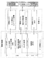
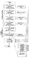
上述の種類のシステムでは、加入者局と基地局との間でコネクション(マネジメント・コネクション又はトランスポート・コネクション)が維持される間、データは、加入者局と基地局との間のパケット交換により通信される。加入者局から基地局へのパケットの送信方向は上り回線(UL)と称される。また基地局から加入者局への方向は下り回線(DL)と称される。パケットは、システム及びシステムの構成要素の無線装置に適用される階層プロトコルに従う定められたフォーマットを有する。パケットに関するプロトコルの層は、それ自体、所謂、物理層(PHY)及びメディアアクセス層(MAC)である。IEEE802.16−2004仕様では、これらのプロトコル層は、図1に示されるプロトコル・スタックを形成する。 In a system of the type described above, data is obtained by exchanging packets between the subscriber station and the base station while a connection (management connection or transport connection) is maintained between the subscriber station and the base station. Communicated. The transmission direction of the packet from the subscriber station to the base station is called an uplink (UL). The direction from the base station to the subscriber station is called downlink (DL). The packet has a defined format according to the hierarchical protocol applied to the system and the wireless devices of the system components. The protocol layers for packets are themselves the so-called physical layer (PHY) and media access layer (MAC). In the IEEE 802.16-2004 specification, these protocol layers form the protocol stack shown in FIG.
図1に示されるメディアアクセス層は、本願明細書に記載される本発明に最も関連するプロトコル層である。メディアアクセス層は、ネットワークアクセス、帯域割り当て及びコネクション維持を含む種々の機能の処理に関与する。これは、BS及びSSの、システム内で所定の単位時間であり且つ時間領域で多数のスロットに分割される「フレーム」に基づくネットワークへのアクセス制御を含む。データは、MACピアエンティティ間で、換言すると加入者局と基地局との間で、プロトコルデータユニット(PDU)の単位で交換される。PDUはPHY層を渡り多数のスロットを使用して伝達される。従って、「スロット」は帯域を割り当てるために用いられる時間の単位である。MACは、認証、鍵交換及びPDUの暗号化を可能にするセキュリティ副層を有する副層に分割される(図1を参照)。これらの機能及び副層は、大体、より高レベルの機能を有する「MAC上層」又はUMACとより低レベルの、よりスピードが重視される機能を有するMAC低層又はLMACにグループ化されうる。 The media access layer shown in FIG. 1 is the protocol layer most relevant to the present invention described herein. The media access layer is responsible for processing various functions including network access, bandwidth allocation and connection maintenance. This includes BS and SS access control to the network based on “frames” that are a predetermined unit time in the system and are divided into a number of slots in the time domain. Data is exchanged in units of protocol data units (PDUs) between MAC peer entities, in other words, between subscriber stations and base stations. PDUs are transmitted using multiple slots across the PHY layer. Thus, a “slot” is a unit of time used to allocate bandwidth. The MAC is divided into sublayers with a security sublayer that allows authentication, key exchange and PDU encryption (see FIG. 1). These functions and sub-layers can be roughly grouped into a “MAC upper layer” with higher level functions or a MAC lower layer or LMAC with UMAC and lower level, more speed sensitive functions.
UMACは、通常、汎用プロセッサでソフトウェアを実行することにより実施され、更新及びシステム変更が要求されたときの再設定を可能にする。UMACの機能は、図1に示すようにMAC管理、サービス依存コンバージェンス層及びMAC共通副層(MAC CPS、図1を参照)を有する。LMACも、プロセッサにより実行されるソフトウェアにより提供されてよいが、本例では低レベルのコード(場合によってはプロセッサに実装される)及び/又はリアルタイム・オペレーティング・システムが必要である。LMACは、UMACとPHYとの間のブリッジとして動作し、データ暗号化/復号化(図1に示すセキュリティ副層の機能)、誤り訂正コード(CRC)の生成、PDU分類及び以下に更に説明するブロック処理を実行することにより、UMACのタスクの幾つかをオフロードする。 UMAC is typically implemented by executing software on a general purpose processor and allows reconfiguration when updates and system changes are required. The UMAC function has a MAC management, service-dependent convergence layer and a MAC common sublayer (MAC CPS, see FIG. 1) as shown in FIG. The LMAC may also be provided by software executed by the processor, but this example requires low-level code (possibly implemented in the processor) and / or a real-time operating system. LMAC acts as a bridge between UMAC and PHY, data encryption / decryption (security sub-layer function shown in FIG. 1), error correction code (CRC) generation, PDU classification and further described below. Offload some of the UMAC tasks by performing block processing.
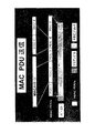
データの送信を考えると、データ・フローは一般的にプロトコル・スタックの上位から下位へ流れる。従って、例えば、データ・パケット(又は所謂、サービス・データ・ユニット、SDU、以下に更に詳細に記載する)は、プロトコル・スタックの上位(アプリケーション層、図1に示さない)から、図1のCS SAPを介して送信される。UMACでは、SDUはLMACへの送信キューに入れられ、サブフレームを構成するために(「パッキング」と称されるプロセスで)MAC PDUに変換される。SDU及びPDUのデータ・サイズは一致する必要がないので、所謂「フラグメンテーション」も必要とされる。フラグメンテーションでは、単一のSDUは複数のMAC PDUの間で分割される。物理層では、サブフレームの構成要素を電磁波の多数の「バースト」のうちの1つに割り当てることにより、組み立てられたサブフレームが送信のために準備される。図2はSDU、PDU及びバーストの間の関係を概略的に示す。 Considering data transmission, the data flow generally flows from the top to the bottom of the protocol stack. Thus, for example, data packets (or so-called service data units, SDUs, described in more detail below) are sent from the upper layer of the protocol stack (application layer, not shown in FIG. 1) from the CS of FIG. Sent via SAP. In UMAC, SDUs are queued for transmission to LMAC and converted to MAC PDUs (in a process called “packing”) to construct subframes. Since the data sizes of the SDU and PDU do not need to match, so-called “fragmentation” is also required. In fragmentation, a single SDU is divided among multiple MAC PDUs. At the physical layer, the assembled subframe is prepared for transmission by assigning the subframe components to one of a number of "bursts" of electromagnetic waves. FIG. 2 schematically shows the relationship between SDUs, PDUs and bursts.
バーストでは、前方誤り訂正(FEC)が用いられ、受信機が送信処理により導入された誤りを訂正するのを助ける。各バーストは、図2に示したように複数のFECブロックを有しうる。MAC PDUはFECブロック内に含まれ、MAC PDUはFECブロックの複数の境界に跨ってよい。 In bursts, forward error correction (FEC) is used to help the receiver correct errors introduced by the transmission process. Each burst may have multiple FEC blocks as shown in FIG. The MAC PDU may be included in the FEC block, and the MAC PDU may straddle multiple boundaries of the FEC block.
利用可能な周波数範囲及びアプリケーションに依存して、種々の物理層の実装がIEEE802.16ネットワークで可能である。例えば、以下に記載される時分割二重(TDD)方式及び周波数分割二重(FDD)方式である。PHY層はまた、OFDM(直交周波数分割多重)又はOFDMA(直交周波数分割多重アクセス)のような伝送技術を定める。これらの技術は以下に簡単に説明される。 Depending on the available frequency range and application, various physical layer implementations are possible in an IEEE 802.16 network. For example, a time division duplex (TDD) scheme and a frequency division duplex (FDD) scheme described below. The PHY layer also defines transmission techniques such as OFDM (Orthogonal Frequency Division Multiplexing) or OFDMA (Orthogonal Frequency Division Multiplexing Access). These techniques are briefly described below.
OFDMでは、単一のデータストリームがN個の並列のサブキャリアに変調される。各サブキャリアの信号はそれぞれの周波数範囲を有する。これは、全帯域(つまり所与の時間間隔で送信されるべきデータ量)を複数のサブキャリアに渡り分割し、それにより各データ・シンボルの期間を増大する。各サブキャリアは低い情報レートを有するので、複数搬送波システムは単一搬送波システムと比べてチャンネルに導入される歪みが少ないので有利である。これは、送信レート、従って各サブキャリアの帯域幅がチャンネルのコヒーレンス帯域幅より小さいことを保証することにより可能になる。結果として、単一搬送波で被るチャンネル歪みは周波数に依存せず、従って単純な位相及び振幅補正係数により補正できる。従って、複数搬送波受信機内でチャンネル歪みを補正することにより、システムの帯域幅がチャンネルのコヒーレンス帯域幅を超えている場合に、単一搬送波受信機内の対向部分の複雑性を有意に低下しうる。 In OFDM, a single data stream is modulated onto N parallel subcarriers. Each subcarrier signal has a respective frequency range. This divides the entire band (ie, the amount of data to be transmitted in a given time interval) across multiple subcarriers, thereby increasing the duration of each data symbol. Since each subcarrier has a low information rate, a multi-carrier system is advantageous because it introduces less distortion into the channel than a single carrier system. This is made possible by ensuring that the transmission rate, and thus the bandwidth of each subcarrier, is less than the coherence bandwidth of the channel. As a result, the channel distortion experienced by a single carrier is frequency independent and can therefore be corrected by simple phase and amplitude correction factors. Thus, correcting for channel distortion in a multi-carrier receiver can significantly reduce the complexity of the opposing parts in a single-carrier receiver when the system bandwidth exceeds the channel coherence bandwidth.
OFDMシステムは複数のサブキャリア周波数を用いる。複数のサブキャリア周波数は数学的意味で直交するので、サブキャリアのスペクトルが相互に独立であるという事実により、サブキャリアは干渉せずに重なり合う。OFDMシステムの直交性は帯域周波数を保護する必要がなく、それによりシステムのスペクトル効率を向上する。OFDMは多くの無線システムに提案され適用されている。OFDMシステムでは、逆離散又は高速フーリエ変換アルゴリズム(IDFT/IFFT)を用いることにより、N個の変調された並列データ源の信号ブロックがN個の直交する並列サブキャリアにマッピングされ、送信機で時間領域の「OFDMシンボル」として知られる信号を形成する。従って、「OFDMシンボル」はN個のサブキャリア信号全ての複合信号である。受信機で、受信された時間領域信号は、離散フーリエ変換(DFT)又は高速フーリエ変換(FFT)アルゴリズムを適用することにより周波数領域に変換して戻される。 An OFDM system uses multiple subcarrier frequencies. Since the subcarrier frequencies are orthogonal in the mathematical sense, the subcarriers overlap without interference due to the fact that the subcarrier spectra are independent of each other. The orthogonality of the OFDM system does not need to protect the band frequency, thereby improving the spectral efficiency of the system. OFDM has been proposed and applied in many wireless systems. In an OFDM system, by using an inverse discrete or fast Fourier transform algorithm (IDFT / IFFT), the signal blocks of N modulated parallel data sources are mapped to N orthogonal parallel subcarriers and are transmitted in time by the transmitter. Forms a signal known as the “OFDM symbol” of the region. Therefore, an “OFDM symbol” is a composite signal of all N subcarrier signals. At the receiver, the received time domain signal is transformed back to the frequency domain by applying a discrete Fourier transform (DFT) or fast Fourier transform (FFT) algorithm.
OFDMA(直交周波数分割多重アクセス)はOFDMの多重アクセス版である。OFDMAはサブキャリアのサブセットを個々のサブキャリアに割り当てることにより動作する。これは、複数のユーザからの同時送信を許容し、一層良好なスペクトル効率をもたらす。しかしながら、双方向通信の実現、つまり上り及び下り方向に干渉のない通信可能にするという課題が依然として存在する。 OFDMA (Orthogonal Frequency Division Multiple Access) is a multiple access version of OFDM. OFDMA operates by assigning a subset of subcarriers to individual subcarriers. This allows simultaneous transmissions from multiple users, resulting in better spectral efficiency. However, there is still a problem of realizing bidirectional communication, that is, enabling communication without interference in the upstream and downstream directions.
2つのノード間で双方向通信を実現するために、2つの良く知られた異なる手法が存在する。これらの手法は、2つの(順方向又は下り、及び逆方向又は上り)通信リンクを二重にして、装置が同一のリソース媒体で同時に送信及び受信できないという物理的制約を克服する。第1の手法である周波数分割二重(FDD)は、2つのリンクを同時に動作するが、送信媒体を2つの別個の帯域、つまり1つはDL通信のため、もう1つはUL通信のために分割することにより異なる周波数帯域で動作する。第2の手法である時分割二重(TDD)は、2つのリンクを同一周波数帯で動作させるが、媒体への同時アクセスを分割し、如何なる時点においてもDL又はULのみが媒体を使用する。2つの手法(TDD及びFDD)はそれぞれの利点を有し、共に単一ホップ有線及び無線通信システムに良く利用される技術である。IEEE802.16規格はFDDとTDD方式の両方を盛り込んでいるが、本願明細書では以下にTDD方式に関して主に記載する。 There are two well-known different approaches to achieve bi-directional communication between two nodes. These approaches duplicate the two (forward or downstream and reverse or upstream) communication links to overcome the physical limitation that devices cannot transmit and receive simultaneously on the same resource medium. The first approach, Frequency Division Duplex (FDD), operates two links simultaneously, but transmits the transmission medium in two separate bands, one for DL communication and one for UL communication. By dividing into two, it operates in different frequency bands. The second approach, time division duplex (TDD), operates two links in the same frequency band, but divides simultaneous access to the medium, and only DL or UL uses the medium at any given time. The two approaches (TDD and FDD) have their advantages and are both commonly used techniques for single-hop wired and wireless communication systems. The IEEE 802.16 standard includes both the FDD and TDD systems, but the present specification mainly describes the TDD system below.
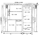
図3及び4はIEEE802.16規格(WiMAX)のOFDMA物理層モードで用いられるTDDフレーム構造を示す。 3 and 4 show the TDD frame structure used in the OFDMA physical layer mode of the IEEE 802.16 standard (WiMAX).
図3では、フレームは所与の時間長及び所与の周波数帯、つまり図3に「OFDMシンボル数」により示される時間軸、及び「サブチャネル数」(各サブチャネルは上述のサブキャリアのセットである)により示される周波数軸を占有すると考えられる。各フレームは、それぞれ別個の送信間隔であるDL及びUL下位フレームに分割される。それらは送信/受信及び受信/送信遷移保護間隔(それぞれTTG及びRTG)により分離される。各DL下位フレームはプリアンブルで始まり、次にフレーム制御ヘッダ(FCH)、DL−MAP、そしてUL−MAPが続く。FCHはDLフレーム・プレフィックス(DLFP)を含み、バースト特性及びDL−MAPの長さを指定する。DLFPは各フレームの始めに送信されるデータ構造であり、FCHにマッピングされる現在のフレームに関する情報を含む。同時DL割り当ては、ブロードキャスト、マルチキャスト及びユニキャストであり、それらはBSにサービスを提供するというより、別のBSのための割り当てを含む。同時ULはデータ割り当て及びレンジング又は帯域幅要求であってよい。 In FIG. 3, a frame is a given time length and a given frequency band, that is, a time axis indicated by “number of OFDM symbols” in FIG. Is considered to occupy the frequency axis indicated by Each frame is divided into DL and UL lower frames, which are separate transmission intervals. They are separated by the transmit / receive and receive / transmit transition protection intervals (TTG and RTG, respectively). Each DL subframe begins with a preamble, followed by a frame control header (FCH), DL-MAP, and UL-MAP. The FCH includes a DL frame prefix (DLFP) and specifies burst characteristics and the length of the DL-MAP. DLFP is a data structure transmitted at the beginning of each frame and includes information about the current frame mapped to the FCH. Simultaneous DL assignments are broadcast, multicast and unicast, which include assignments for another BS rather than serving a BS. The simultaneous UL may be data allocation and ranging or bandwidth request.
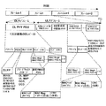
図4は、ULサブフレーム内に2つの部分、つまりPHYヘッダ及びMAC PDUを有する異なる観点からのOFDMA TDDフレーム構造を説明する。MAC PDUはまた、MACヘッダ、任意のペイロード及び任意の誤り訂正符号(巡回冗長符号又はCRC)を有する。PHY層ヘッダは、トレーニングシーケンス、周波数帯割り当て情報及び物理層パラメータに関する他の情報を有する。MAC PDU内で、MACヘッダは通常、PDUの種類、MACアドレス及びMAC信号の種類等のような媒体アクセスのために不可欠なパラメータを与える。MAC PDU内のCRCは任意であり、受信したMAC PDUを検査するために使用されうる。MAC PDU内のペイロードは、SSがBSへ送信したいデータを含めるために用いられるが、任意である。例えば、帯域要求のような制御メッセージ又はACKメッセージは、如何なるペイロードも有さない。ペイロードは、より高位の層のデータ又は追加MAC情報を与えうる副MACヘッダであり得る。 FIG. 4 illustrates an OFDMA TDD frame structure from a different point of view having two parts in a UL subframe: a PHY header and a MAC PDU. The MAC PDU also has a MAC header, an optional payload, and an optional error correction code (Cyclic Redundancy Code or CRC). The PHY layer header includes training sequence, frequency band allocation information, and other information related to physical layer parameters. Within a MAC PDU, the MAC header typically provides essential parameters for media access such as PDU type, MAC address and MAC signal type. The CRC in the MAC PDU is arbitrary and can be used to inspect the received MAC PDU. The payload in the MAC PDU is used to contain data that the SS wants to send to the BS, but is optional. For example, a control message such as a bandwidth request or an ACK message does not have any payload. The payload may be a secondary MAC header that may provide higher layer data or additional MAC information.
また、802.16eのOFDMAは、ネットワーク性能を管理するより良い手段としてサブチャネル化を提供し、依存コンバージェンス層及び能力要件を解決する。OFDMA物理層は、利用可能なOFDMシンボル及び構成要素であるサブキャリア(図3を参照)を、別個の論理的及び物理的サブチャネルに分割し、図3に示すように複数のバーストの共存又は各時間間隔での重なり合いを許容する。下り回線では単一のバーストが複数のユーザ(加入者局)により共有されてよいが、上り回線では各バーストは一般的に単一のユーザに対応する。OFDMAサブチャネル化技術は、周波数分割及び周波数選択性伝送スキームを含む。 802.16e OFDMA also provides sub-channelization as a better means of managing network performance, resolving dependent convergence layers and capability requirements. The OFDMA physical layer divides the available OFDM symbols and the constituent subcarriers (see FIG. 3) into separate logical and physical subchannels, so that multiple bursts can coexist or Allow overlap at each time interval. In the downlink, a single burst may be shared by multiple users (subscriber stations), but in the uplink, each burst generally corresponds to a single user. OFDMA subchannelization techniques include frequency division and frequency selective transmission schemes.
周波数分割伝送スキームは、全帯域を用いたサブチャネル化(Full Usage of Subchannels:FUSC)及び帯域の一部を用いたサブチャネル化(Partial Usage of Subchannels:PUSC)モードにグループ化されうる。これらのモードは、周波数分割伝送に対応する。周波数分割伝送では、各論理サブチャネルに割り当てられたサブキャリアは利用可能なサブキャリアのセットに渡り疑似的にランダムに分散される。FUSCでは、サブキャリアは周波数範囲全域に分散されるが、PUSCでは、サブキャリアの幾つかの分散されたクラスタがサブチャネルを形成するために用いられる。これらのスキームは、変化するチャネル条件を扱うのに一層適しており且つネットワーク・カバレッジ及び能力に利益をもたらす周波数ダイバーシティを提供する。 Frequency division transmission schemes can be grouped into sub-channelization (Full Usage of Subchannels: FUSC) using the entire band and sub-channelization (Partial Usage of Subchannels: PUSC) mode using a part of the band. These modes correspond to frequency division transmission. In frequency division transmission, the subcarriers assigned to each logical subchannel are pseudo-randomly distributed over the set of available subcarriers. In FUSC, subcarriers are distributed across the frequency range, whereas in PUSC, several distributed clusters of subcarriers are used to form subchannels. These schemes are better suited to handle changing channel conditions and provide frequency diversity that benefits network coverage and capabilities.
周波数選択性サブチャネル化は、帯域適応型変調及び符号化(Adaptive Modulation and Coding:AMC)モードで対応される。帯域AMCは、物理的に隣接するサブキャリア配置、つまりサブキャリアの連続するグループを通じてサブチャネル構成を許容する。システム・スケジューラは、閉ループのチャネル帰還技術を利用し、固有のチャネル条件に基づき各サブキャリアに割り当てられるべき最適なサブチャネルを決定しうる。図6は、FUSC、PUSC及びAMCゾーンを有するOFDMA TDDモードのフレーム構成を示す。一般に、FUSC及びPUSCは基地局と移動局との間の接続に適している。一方でAMCは固定加入者局との接続に適している。 Frequency selective subchannelization is supported in a band adaptive modulation and coding (AMC) mode. Band AMC allows subchannel configurations through physically adjacent subcarrier arrangements, i.e., consecutive groups of subcarriers. The system scheduler may utilize a closed loop channel feedback technique to determine the optimal subchannel to be assigned to each subcarrier based on unique channel conditions. FIG. 6 shows a frame structure of an OFDMA TDD mode having FUSC, PUSC, and AMC zones. In general, FUSC and PUSC are suitable for connection between a base station and a mobile station. On the other hand, AMC is suitable for connection with a fixed subscriber station.
サブチャネル化は、隣接するセルの間で周波数を割り当てる周波数再利用スキームにとって重要である。恐らく、最も一般的な再利用スキームは「リユース3」(再利用係数3)と称される。このスキームでは、干渉を低減するために、六角形のセルは、隣接するセルの各対が周波数チャネルの異なるセットを割り当てられていると考えられる。チャネルの3個のセットはこれを達成するのに十分である。PUSC又はFUSCは、この場合に適切な伝送スキームである。何故なら、サブキャリアのサブチャネルへのランダムな割り当てにより、異なるセル内の信号間の干渉の可能性が一層最小化されるからである。一方で「リユース1」は単に各セル内で同一の周波数セットを用いることを意味する(再利用係数1)。これは、干渉を増大させるが(CINRを減少させる)、利用可能な周波数範囲の全体(図3の全てのサブチャネル)が各接続により用いられることを可能にし、且つ単純なので実在のシステム内に実装できる。異なる再利用スキームを単一のセル内の異なるサブキャリアに対し同時に用いることが可能である。特に、リユース3はセルの端に近いユーザに適し、一方でリユース1は他のセルからの干渉が起こりにくいセルの中央に近いサブキャリアに安全に用いることができる。これは結果として1と3の間のどこかのシステムに対し「効率的な再利用係数」になる。通常、セルはそれぞれ個々の中央に位置する基地局を設けられるが、次第に複数方向のアンテナが単一の基地局に取り付けられ、同一の基地局が該基地局の周りの複数のセルにサービスを提供できるようになっている。
Subchannelization is important for frequency reuse schemes that allocate frequencies between adjacent cells. Perhaps the most common reuse scheme is called “
DLサブフレームは、DL−MAPとUL−MAPを備えたブロードキャスト制御フィールドを含む。これらにより、BSは受信装置にフレーム構造を知らせる。MAPはフレーム内の帯域幅割り当てのマップであり、それぞれコネクションIDを有する情報要素(IE)も含む。マップのIEは、加入者局に、当該加入者局が情報を受信するよう割り当てられたバーストを知らせる。従って、TDD方式のネットワークでは、帯域幅割り当てはフレーム内の資源(スロット)の割り当てを意味する。DL−MAPとUL−MAPはBSによる管理メッセージのブロードキャスト(つまり全ての加入者へ送信される)の例である。他の管理メッセージは、上りリンク・チャネル記述子UCDと下りリンク・チャネル記述子DCD(両方とも図4に示す)、動的サービス要求及び応答(DS−REQ及び−RSP)を含む。 The DL subframe includes a broadcast control field with DL-MAP and UL-MAP. As a result, the BS informs the receiving apparatus of the frame structure. MAP is a map of bandwidth allocation within a frame, and also includes information elements (IE) each having a connection ID. The IE of the map informs the subscriber station of the bursts that the subscriber station is assigned to receive information. Therefore, in a TDD network, bandwidth allocation means allocation of resources (slots) in a frame. DL-MAP and UL-MAP are examples of broadcast of management messages by BS (that is, transmitted to all subscribers). Other management messages include uplink channel descriptor UCD and downlink channel descriptor DCD (both shown in FIG. 4), dynamic service request and response (DS-REQ and -RSP).
サービスの質(QoS)の概念は、幅広いサービスの提供を可能にするため無線通信システムで利用される。提供されるサービスの種類(以下を参照)に依存して、パケットは、ある程度の精度及び/又はある時間遅延内に送信される必要がある。或いは、パケットは壊れており、場合によっては再送信を要求する必要がある。加入者局との通信中、基地局は、加入者局により要求されたサービスの種類及び利用可能な帯域に依存して、基地局が標準的に複数の加入者局と同時に通信することを念頭に置き、QoSレベルを割り当てる。QoSパラメータは、送信の優先度(時間遅延、又は待ち時間)、送信の精度(誤り率)及びスループット(データ・レート)を考慮に入れる。 The concept of quality of service (QoS) is used in wireless communication systems to enable the provision of a wide range of services. Depending on the type of service provided (see below), the packet needs to be transmitted within a certain degree of accuracy and / or some time delay. Alternatively, the packet is corrupted and may need to be retransmitted in some cases. During communication with a subscriber station, the base station keeps in mind that the base station typically communicates with multiple subscriber stations simultaneously, depending on the type of service requested by the subscriber station and the available bandwidth. And assign a QoS level. The QoS parameters take into account transmission priority (time delay or latency), transmission accuracy (error rate) and throughput (data rate).
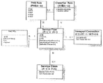
基地局と加入者局との間のコネクション(より詳細には、それら装置、所謂ピアエンティティのMAC層間)はコネクション識別子(CID)を割り当てられ、基地局は基地局のアクティブなコネクションを管理するためCIDを追跡し続ける。アドレス付与及びQoS制御に対応するため、ある無線通信システムは、MACヘッダにコネクション識別子(CID)を付す。例えばWiMAXでは、SS/MSとBSとの間のサービス・フローは、ネットワーク・エントリ手順の間に又は動的サービス・フロー手順により作成され及び活性化され得る。前述のように、サービス・フローID(SFID)は、存在するサービス・フローにそれぞれ割り当てられる。また各サービス・フローは特定のQoS要求と関連付けられる。サービス・フローは、少なくとも1つのSFID及び関連する方向を有する。トランスポート・コネクションのコネクション識別子(CID)は、サービス・フローが許可された又はアクティブである場合のみ存在する。SFIDとトランスポートCIDとの間の関係は一意的である。これはSFIDが1つより多いトランスポートIDに関連付けられるべきでないこと及びトランスポートCIDが1つより多いSFIDに関連付けられるべきでないことを意味する。 The connection between the base station and the subscriber station (more specifically, those devices, the so-called MAC layer of the peer entity) is assigned a connection identifier (CID) so that the base station manages the active connection of the base station. Keep track of CID. In order to support address assignment and QoS control, some wireless communication systems attach a connection identifier (CID) to the MAC header. For example, in WiMAX, the service flow between SS / MS and BS can be created and activated during network entry procedure or by dynamic service flow procedure. As described above, a service flow ID (SFID) is assigned to each existing service flow. Each service flow is also associated with a specific QoS request. A service flow has at least one SFID and an associated direction. The connection identifier (CID) of the transport connection exists only when the service flow is permitted or active. The relationship between SFID and transport CID is unique. This means that the SFID should not be associated with more than one transport ID and the transport CID should not be associated with more than one SFID.
BSは、スケジューラ(スケジューリング・アルゴリズム)を用い、現在アクティブな全てのコネクションへの帯域幅(スロット)の割り当てを管理し、種々の加入者の要求の平衡をとる。つまり、各SSは、ネットワーク・エントリに対し1回だけ交渉する必要がある。その後、BSにより割り当てられた帯域幅は、SSからの要求により又はネットワークの他の必要により増大又は減少するが、当該SSへ割り当てられたままであり、従ってコネクションをアクティブのままにする。 The BS uses a scheduler (scheduling algorithm) to manage the allocation of bandwidth (slots) to all currently active connections and balance the demands of various subscribers. That is, each SS needs to negotiate only once for the network entry. Thereafter, the bandwidth allocated by the BS increases or decreases due to requests from the SS or due to other needs of the network, but remains allocated to that SS, thus leaving the connection active.
スケジューラは、可能な限り、現行のフレーム(特に基地局で構成されるDLサブフレーム)内でサービスを提供される必要のある全てのコネクションが幾つかのリソース(帯域幅)を受けることを保証しなければならない。このQoS要件とは別に、考慮されるべき他の要因には、基地局から各加入者への距離(経路損失)及び必要に応じて加入者の移動度が含まれる。加入者が基地局から遠い場合又は遠くに移動している場合、下り回線で実現可能な伝送レートは、基地局に近い加入者を優先的に取り扱うために(システム性能の観点から)より効率的になるよう低減される。他方で、如何なる加入者もデータがなくなることは許容できない。 Whenever possible, the scheduler guarantees that all connections that need to be serviced within the current frame (especially the DL subframe consisting of base stations) will receive some resources (bandwidth). There must be. Apart from this QoS requirement, other factors to be considered include the distance from the base station to each subscriber (path loss) and, if necessary, the mobility of the subscriber. When the subscriber is far away or moving far from the base station, the transmission rate achievable on the downlink is more efficient (from a system performance perspective) to preferentially treat subscribers close to the base station To be reduced. On the other hand, it is unacceptable for any subscriber to lose data.
これらの要因のバランスを取ることを狙ったある技術は、「比例公平(PF)」アルゴリズムと称される。該アルゴリズムは、全ての加入者に提供される長期平均データ・レートの対数を最大化することにより、システム性能と加入者に対する公平との間のバランスを達成することを目的とする。 One technique that seeks to balance these factors is called a “proportional fair (PF)” algorithm. The algorithm aims to achieve a balance between system performance and fairness for subscribers by maximizing the log of the long-term average data rate provided to all subscribers.
前述のように、各コネクションは、サービス・クラスと関連付けられたQoSを有する。QoSは、最初に、加入者局がネットワークへ参加するときのネットワーク・エントリ手順(コネクション確立段階)の間に割り当てられ、そしてその後、コネクションが維持されている間、基地局への要求を行う加入者局により変更されてよい。これは、ネットワーク内で利用可能なリソースに依存して、おそらく繰り返し、コネクションへの追加の帯域幅の割り当てを伴う。 As described above, each connection has a QoS associated with the service class. QoS is initially assigned during the network entry procedure (connection establishment phase) when a subscriber station joins the network, and then the subscription making a request to the base station while the connection is maintained. It may be changed by the person station. This may involve repeated allocation of additional bandwidth to the connection, possibly repeatedly, depending on the resources available in the network.
QoSとCID/SFIDとの間の関係は、図5に図示される。図5の理解を簡単にするため、留意すべき点は、「サービス・フロー(Service flow)」が、特定のQoSを有するコネクションでの所与の方向(上り回線又は下り回線)のデータ送信を示すことである。コネクションのQoSは、コネクション識別子と1対1の関係を有するサービス・フロー識別子(SFID)により定められる。厳密には、サービス・フロー(又はコネクション)に帯域幅が割り当てられるのだが、BSによりコネクションに含まれるSSに割り当てられている帯域幅を考慮するのが都合がよい。各サービス・フローは、サービス・クラス又はQoSクラスのセットの1つに分類されうる。基本的にDLとULの両者に対して同一であるが、これらのサービス・クラスは、DL及びULスケジューラの観点からは僅かに異なるよう定められる。DL及びULのQoS配信のメカニズムの間には差異がある。この差異は、BSがMSにあるバッファ状態を直接見ることができず、MSでのパケット誤りレートを知らないかも知れないという事実に起因する。 The relationship between QoS and CID / SFID is illustrated in FIG. To simplify the understanding of FIG. 5, it should be noted that a “service flow” is a data transmission in a given direction (uplink or downlink) over a connection with a specific QoS. Is to show. The QoS of the connection is determined by a service flow identifier (SFID) having a one-to-one relationship with the connection identifier. Strictly speaking, bandwidth is allocated to the service flow (or connection), but it is convenient to consider the bandwidth allocated to the SS included in the connection by the BS. Each service flow can be classified into one of a set of service classes or QoS classes. Although basically the same for both DL and UL, these service classes are defined to be slightly different from a DL and UL scheduler perspective. There are differences between the mechanisms of DL and UL QoS delivery. This difference is due to the fact that the BS cannot directly see the buffer status at the MS and may not know the packet error rate at the MS.
<下り回線(DL)>
以下のサービス・クラス・タイプはIEEE802.16で定められている。
−UGS:アンソリシテッド・グラント・サービス(Unsolicited grant service)
−RT−VR:リアルタイム可変レート・サービス(Real-time variable rate Service)
−ERT−VR:拡張リアルタイム可変レート・サービス(Extended Real-time variable rate Service)
−NRT−VR:非リアルタイム可変レート・サービス(Non Real-time variable rate Service)
−BE:ベストエフォート・サービス(Best Effort service)。
<Downlink (DL)>
The following service class types are defined in IEEE 802.16.
-UGS: Unsolicited grant service
-RT-VR: Real-time variable rate service
-ERT-VR: Extended Real-time variable rate Service
-NRT-VR: Non Real-time variable rate Service
-BE: Best Effort service.
表1は、目的の簡単な説明を提供し、各サービス・クラスと関連付けられたパラメータを列挙する。これらのパラメータを表2に説明する。
[表1]DLのサービス・タイプの概要
[Table 1] Overview of DL service types
[表2]パラメータの説明
下り回線のパケット・スケジューラの役割は、設定されたパラメータ設定に基づきアクティブなサービス・フロー毎に設定された要件が満たされることを保証することである。 The role of the downlink packet scheduler is to ensure that the requirements set for each active service flow are met based on the set parameter settings.
<上り回線(UL)>
以下のサービス・クラス・タイプ及びスケジューリング・サービスは、IEEE802.16規格で定められ、WiMAX Forum Mobile System Profileで支持されている。
−UGS:アンソリシテッド・グラント・サービス(Unsolicited grant service)
−rtPS:リアルタイム・ポーリング・サービス(Real-time Polling Service)
−ertPS:拡張リアルタイム・ポーリング・サービス(Extended Real-time Polling Service)
−nrtPS:非リアルタイム・ポーリング・サービス(Non-Real-time Polling Service)
−BE:ベストエフォート・サービス(Best Effort service)
<Uplink (UL)>
The following service class types and scheduling services are defined in the IEEE 802.16 standard and are supported by the WiMAX Forum Mobile System Profile.
-UGS: Unsolicited grant service
-RtPS: Real-time Polling Service
-ErtPS: Extended Real-time Polling Service
-NrtPS: Non-Real-time Polling Service
-BE: Best Effort service
表3は、目的の簡単な説明を提供し、各サービス・クラスと関連付けられたパラメータを列挙する(パラメータの説明は表2に示す)。
[表3]ULのサービス・タイプの概要
[Table 3] Overview of UL service types
上り回線のパケット・スケジューラの役割は、設定されたパラメータ設定に基づき、MS CIDに適切にリソースを割り当てることにより、アクティブなサービス・フロー毎に設定された要件が満たされることを保証することである。特にULの場合には、スケジューラはポーリング間隔を有するサービス・フロー(例えばrtPS又はnrtPS)若しくはPMビットセットを有するUGSコネクションの許可又はフロー・パラメータに基づくアンソリシテッドな許可の要求のためにポーリングの機会(BW要求を送信するのに十分なBW)も提供しなければならない。 The role of the uplink packet scheduler is to ensure that the requirements set for each active service flow are met by appropriately allocating resources to the MS CID based on the set parameter settings. . In particular, in the case of UL, the scheduler may poll for a service flow with a polling interval (eg rtPS or nrtPS) or a UGS connection with PM bit set or a request for an unsolicited grant based on flow parameters ( Sufficient BW to send a BW request) must also be provided.
ULでは、スケジューラは、MSの現在の要件に関するMSから受信した情報を検討する必要もある。これらの要件は次のものを含む。
−許可管理サブヘッダ内のPBR、PM、SI、FL及びFLIビット(以下を参照)
−MACシグナリング・タイプIヘッダ内のBR(付加的又は集合体)
−CDMA BW要求
In UL, the scheduler also needs to review information received from the MS regarding the current requirements of the MS. These requirements include the following:
-PBR, PM, SI, FL and FLI bits in permission management subheader (see below)
-BR (additional or aggregate) in MAC signaling type I header
-CDMA BW request
これらの情報項目の更なる詳細を以下の表に示す。
<対応するクラス及びパラメータ>
表4はサービス・クラス毎にどのパラメータが必須か、任意か又は適用できないかを示す。
[表4]種類毎に対応するサービス・クラスのパラメータ
Table 4 shows which parameters are required, optional or not applicable for each service class.
[Table 4] Service class parameters corresponding to each type
以上の説明から明らかなように、基地局内のUL及びDLのパケット・スケジューラのタスクが大いに関連する。しかしながら、WiMAXシステムでは、商業的に成功するためには基地局の機能は低価格で提供されなければならない。従って、簡単な方法で上述のスケジューリング機能を提供し、必要な処理能力及びその価格を最小限に抑えるようにする必要がある。 As is apparent from the above description, the UL and DL packet scheduler tasks within the base station are highly relevant. However, in WiMAX systems, base station functionality must be provided at a low price to be commercially successful. Therefore, there is a need to provide the scheduling function described above in a simple way to minimize the required processing power and its price.
より詳細には、効果的且つ費用効率の高いLMACスケジューラ及びPDU形成部を提供するサブシステムが必要である。 More particularly, there is a need for a subsystem that provides an effective and cost-effective LMAC scheduler and PDU generator.
本発明の第1の態様によると、無線通信システムの基地局で用いられるモジュールが提供される。当該無線通信システムでは少なくともデータのパケットが当該基地局から複数の加入者局へ送信され、当該基地局は、前記加入者局とのコネクションを定め、各コネクションは、複数のサービス・クラスのうちの1つを有し、各サービス・クラスは関連するQoSを有し、当該モジュールは、所定の単位時間内で利用可能なシステムのリソースを各コネクションに割り当て、当該モジュールは:前記コネクションの前記QoS要件に応じて、該コネクションのQoSを達成するために前記所定の単位時間内でスケジューリングされる必要のあるコネクションを決定する第1段階のスケジューリング手段;前記スケジューリングされる必要のあるコネクションにリソースを割り当てた後に依然として利用可能なリソースを用いて、前記所定の単位時間内でスケジューリングできる他のコネクションを決定し、QoS以外の要件に基づき該他のコネクションの優先順位を割り当てる第2段階のスケジューリング手段;及び前記第1段階のスケジューリング手段及び前記第2段階のスケジューリング手段により行われた決定に従いリソースを各コネクションに割り当てるリソース割り当て手段;を有する。 According to a first aspect of the present invention, a module for use in a base station of a wireless communication system is provided. In the wireless communication system, at least a packet of data is transmitted from the base station to a plurality of subscriber stations, the base station defines a connection with the subscriber station, and each connection includes a plurality of service classes. Each service class has an associated QoS, the module allocates system resources available within a given unit time to each connection, the module: the QoS requirements for the connection First stage scheduling means for determining a connection that needs to be scheduled within the predetermined unit time to achieve the QoS of the connection; resources are allocated to the connection that needs to be scheduled Using the resources that are still available later, the predetermined unit Second stage scheduling means for determining other connections that can be scheduled in time and assigning priorities of the other connections based on requirements other than QoS; and the first stage scheduling means and the second stage scheduling means Resource allocating means for allocating resources to each connection in accordance with the decision made by.
上述のモジュールでは、前記QoS以外の要件は、当該無線通信システムのオペレータにより定められる。前記他のコネクションのスケジューリングの方法を変更するために、当該モジュールは、QoS以外の要件に関する情報を受信する手段を有してよい。第2段階のスケジューリング手段の目的は、当該システムのスペクトル効率を最大化することであってよい。または、比例公平アルゴリズムが加入者に対する公平さを有しスペクトル効率を平衡させるために用いられてよい。 In the above module, requirements other than the QoS are determined by the operator of the wireless communication system. In order to change the scheduling method of the other connection, the module may have means for receiving information on requirements other than QoS. The purpose of the second stage scheduling means may be to maximize the spectral efficiency of the system. Alternatively, a proportional fair algorithm may be used to balance the spectral efficiency with fairness for the subscriber.
本発明の第2の態様によると、無線通信システムの基地局で用いられるモジュールが提供される。当該無線通信システムでは、データのフレームが複数の加入者局から当該基地局を介して送信され、前記フレームは、時間的に複数のゾーンに分けられ、各ゾーンは、複数のバーストを有し、当該基地局は、複数の隣接する領域内の加入者局から信号を受信し、該加入者局とのコネクションを定め、前記フレーム内のリソースを割り当てることにより該コネクションにサービスを提供し、当該モジュールは:コネクション毎に信号レベルを受信し、該信号レベルと閾レベルとの比較に基づき該コネクションのゾーン割り当てを実行するゾーン割り当て手段;及び該ゾーン割り当て手段によりゾーン割り当てのために用いられる前記閾レベルを選択する部分周波数再利用管理部;を有する。 According to a second aspect of the present invention, a module for use in a base station of a wireless communication system is provided. In the wireless communication system, a frame of data is transmitted from a plurality of subscriber stations via the base station, the frame is divided into a plurality of zones in time, and each zone has a plurality of bursts, The base station receives signals from subscriber stations in a plurality of adjacent areas, defines a connection with the subscriber station, provides a service to the connection by allocating resources in the frame, and the module A zone assignment means for receiving a signal level for each connection and performing zone assignment of the connection based on a comparison between the signal level and a threshold level; and the threshold level used by the zone assignment means for zone assignment A partial frequency reuse management unit.
当該モジュールは、例えば、前記領域のような隣接する六角形セルにサービスを提供するために3セクタのアンテナを有する基地局で用いられる。上述の構成では、望ましくは、ゾーンはリユース1ゾーン及びリユース3ゾーンを有し、該1及び3は前記セルの間の周波数再利用係数を示し、リユース1は、前記セルの間で周波数の再利用がないことを示し、リユース3は、前記周波数が、前記ゾーンにより占有される周波数帯域内でサブチャネルの3つのセットに分けられることを示し、各セットは異なるセルに割り当てられ、前記閾レベルは、最適なリユース3/リユース1の遷移信号レベルである。
The module is used, for example, in a base station having a three sector antenna to serve adjacent hexagonal cells such as the region. In the above configuration, preferably, the zone includes a
本発明の他の態様は、従属請求項に定められるように、上述のモジュールの一方又は両方を有するサブシステム、当該モジュール又はサブシステムを有する基地局、スケジューリング装置、スケジューリング方法、無線通信方法、無線通信システム及び以上に定められたモジュールの機能を実施するソフトウェアを提供する。 Another aspect of the present invention is a sub-system having one or both of the above-mentioned modules, a base station having the module or sub-system, a scheduling device, a scheduling method, a radio communication method, a radio, as defined in the dependent claims. Software for implementing the functions of the communication system and the modules defined above is provided.
例として、添付の図面を参照する。 By way of example, reference is made to the accompanying drawings.
<本発明を実施するモード>
本発明の実施例は、図7−11を参照し、IEEE802.16ネットワークを例として用いて記載される。先ず、WiMAX基地局がQoS配信を保証することを可能にすると共にスペクトル効率を最大化するLMACスケジューラ及びPDU形成部の高レベルの説明を記載する。手短に言うと、これはサービス・フロー・タイプに基づきキューに入れられたパケットのコネクションに基づくパケット・スケジューリング、関連パラメータ及びチャネル状態の考慮の組み合わせを通じて達成される。次に、スケジューラ及びPDU形成部に関連する各構成要素内に含まれる幾つかのアルゴリズムの概略を説明する。
<Mode for carrying out the present invention>
Embodiments of the present invention are described with reference to FIGS. 7-11, using an IEEE 802.16 network as an example. First, a high-level description of the LMAC scheduler and PDU formation unit that allows the WiMAX base station to guarantee QoS delivery and maximizes spectral efficiency is described. In short, this is achieved through a combination of packet scheduling based on connection of packets queued based on service flow type, consideration of relevant parameters and channel conditions. Next, an outline of some algorithms included in each component related to the scheduler and the PDU formation unit will be described.
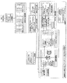
図7は、下り回線の場合のWiMAX基地局のLMACスケジューラ及びMAC PDU形成部の高レベルのアーキテクチャを示す。留意すべき点は、ULスケジューラの場合には、以下に説明するようにデータ・プレーンを形成する要素が必要ないことである。しかしながら実際には、DLスケジューラとULスケジューラの両方を実装するために同一のプロセッサが用いられ、設定のみが変更されるだろう。 FIG. 7 shows a high-level architecture of the LMAC scheduler and MAC PDU formation unit of the WiMAX base station in case of downlink. It should be noted that in the case of the UL scheduler, the elements forming the data plane are not necessary as described below. In practice, however, the same processor will be used to implement both the DL scheduler and the UL scheduler, and only the settings will be changed.
<下り回線(DL)スケジューラ>
下り回線スケジューラ及びPDU形成部の構成要素は、データ又は制御プレーンの部分に分けられる。データ・プレーンは、以下の構成要素を有する。
−(入来パケットの)分類部
−SDUキュー管理部
−SDUデキュー部
−PDU形成部(サブフレーム形成部内にある)
−PHYインターフェース
データ・プレーンの構成要素の全体的な動作は、入り(入力)SDUをキューに入れ、PHY層へ送信するために出(出力)MAC PDUに変換することである。これを達成するために、PDU形成部の機能は、該PDU形成部がどのように動作するかを知らせるバースト・マップ部の機能からの情報を必要とする。
<Downlink (DL) scheduler>
The components of the downlink scheduler and the PDU formation unit are divided into data or control plane parts. The data plane has the following components.
-Classification section (for incoming packets)-SDU queue management section-SDU dequeue section-PDU formation section (in subframe formation section)
-PHY interface The overall operation of the data plane components is to queue incoming (input) SDUs and convert them to outgoing (output) MAC PDUs for transmission to the PHY layer. In order to achieve this, the function of the PDU formation part needs information from the function of the burst map part that informs how the PDU formation part operates.
制御プレーンは、以下の構成要素を有する。
−サービス・フロー管理部
−サブフレーム決定部
−SDUキュー管理部
−FFR管理部
−局管理部
−コネクション・スケジューラ
−バースト・マップ部(サブフレーム形成部内にある)
制御プレーンの構成要素の全体的な動作は、PDU形成部がその機能を実行するために必要とする入力をデータ・プレーン内のPDU形成部に供給し、結果としてPHY層へ送信するためにMAP IEを有するMAPメッセージを構築することである。これは、最終的にバースト・マップ部により提供される。にバースト・マップ部は、示されたように、制御プレーンの他の構成要素からの情報に頼っている。
The control plane has the following components.
-Service flow management unit-Subframe determination unit-SDU queue management unit-FFR management unit-Station management unit-Connection scheduler-Burst map unit (in subframe formation unit)
The overall operation of the control plane components is to provide the input required for the PDU formation part to perform its function to the PDU formation part in the data plane, and consequently to the MAP layer for transmission to the PHY layer. Building a MAP message with an IE. This is finally provided by the burst map section. The burst map portion relies on information from other components of the control plane, as shown.
<上り回線スケジューラ>
図示しないが、上り回線のスケジューラ内の機能的な構成要素は、下り回線のスケジューラ内の構成要素の一部を有する。上り回線の場合には、BSにはデータ・プレーンがなく、代わりにDL構成要素の等価物がMS内に存在している。従って、ULアーキテクチャは、サービス・フロー管理部、局管理部、コネクション・スケジューラ及びサブフレーム形成部のバースト・マップ部のみを有する。
<Uplink scheduler>
Although not shown, the functional components in the uplink scheduler have a part of the components in the downlink scheduler. In the uplink case, there is no data plane in the BS, and instead the DL component equivalent exists in the MS. Therefore, the UL architecture has only a burst map part of a service flow management part, a station management part, a connection scheduler, and a subframe forming part.
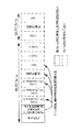
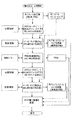
図8は、システム・レベルでコネクション・スケジューリング及びPDU形成のアルゴリズムをフローチャートに基づく表現で示す。フローチャート内の各ブロックの動作を以下に詳細に説明する。 FIG. 8 shows a flowchart based representation of the algorithm for connection scheduling and PDU formation at the system level. The operation of each block in the flowchart will be described in detail below.
<高レベルの構成要素の説明>
(i)局管理部
各承認された加入者局では、局管理部が局の状態情報を有するデータ構造を維持する。状態情報自体は、能動的管理及びトランスポート・コネクションの状態情報を有するデータ構造を有している。構造に含まれる情報は、最低でも、コネクション・スケジューラ及びフレーム形成部により必要とされる。
<Description of high-level components>
(I) Station Manager For each approved subscriber station, the station manager maintains a data structure with station status information. The state information itself has a data structure with active management and transport connection state information. The information contained in the structure is required at a minimum by the connection scheduler and the frame formation unit.
局管理部も、データ構造に影響する多くの機能を有する。該機能は以下を含む。
−ゾーン割り当て:局にサブフレーム内の適切なゾーンを割り当てる。
−バースト・プロファイル割り当て:局にバースト・プロファイルを割り当てる。
−MS/CID状態更新:局/コネクション状態データ構造を更新する。
The station manager also has many functions that affect the data structure. The functions include the following.
-Zone assignment: assign the appropriate zone in the subframe to the station.
Burst profile assignment: Assign a burst profile to a station.
MS / CID status update: Update the station / connection status data structure.
MS/CID状態更新機能は、新たな局情報が受信されたとき(例えば、サービス・フローの変更、CINR報告を受信した、コネクションがスケジューリングされた、新たなSDUが受信されたとき)に開始されてよく、周期的に実行され、SDUキュー長又は待ち時間情報のような情報をフェッチし更新してもよい。 The MS / CID status update function is initiated when new station information is received (eg, service flow change, CINR report received, connection scheduled, new SDU received) It may be executed periodically and fetch and update information such as SDU queue length or latency information.
留意すべき点は、代案としてSDU情報がバースト・マップ部及びSDUキュー管理部からの情報、理論的には新たなSDUが到着するか又はSDUがスケジューリングされたときにSDUキュー管理部からの更新される必要のある情報のみに基づき追跡されうることである。或いは、局管理部によりフレーム毎に待ち時間が増大されうる。この情報は、事象に基づき更新され、SDUキュー管理部からの明示的な更新情報を必要とするか、或いはSDUキュー管理部への周期的な要求に基づき周期的に更新される。 It should be noted that as an alternative SDU information is information from the burst map part and SDU queue manager, theoretically updated from the SDU queue manager when a new SDU arrives or is scheduled It can be tracked based only on the information that needs to be done. Alternatively, the waiting time can be increased for each frame by the station management unit. This information is updated based on events and requires explicit update information from the SDU queue manager, or is periodically updated based on periodic requests to the SDU queue manager.
新たな受信情報に基づき、機能は、ゾーン割り当て又はバースト・プロファイル割り当て機能を開始し、現行の割り当てを更新する。 Based on the new received information, the function initiates a zone assignment or burst profile assignment function and updates the current assignment.
ゾーン割り当て機能及びバースト・プロファイル割り当て機能はSISOユーザのみを扱うとする。DLのMIMOユーザのためのフレームワークを設計することを目的とし(Wave2に対応する必要がある)、MIMO割り当てを可能にするために次の2つの手法がある。
−STC_Zone/DL_Zone_Switch_IEを用いて別個のSISO及びMIMOゾーンを設定する:サブフレーム決定部が別個のゾーンを設定する必要がある。
−MIMO_DL_Basic_IE又はMIMO_DL_Enhanced_IEを用いてSISOゾーン内のMIMOバーストを設定する:サブフレーム決定部がMIMO割り当て用のバーストを設定し、バースト・マップ部がバーストから各MIMOのスケジューリングされたコネクションへ領域を割り当てる必要がある。
Assume that the zone assignment function and burst profile assignment function only handle SISO users. Aiming at designing a framework for DL MIMO users (need to support Wave2), there are two approaches to enable MIMO allocation:
-Set separate SISO and MIMO zones using STC_Zone / DL_Zone_Switch_IE: The subframe decision unit needs to set up separate zones.
-Set up MIMO bursts in the SISO zone using MIMO_DL_Basic_IE or MIMO_DL_Enhanced_IE: subframe decision part needs to set up bursts for MIMO assignment, burst map part needs to allocate area from burst to each MIMO scheduled connection There is.
(ii)コネクション・スケジューラ
コネクション・スケジューラは、フレーム毎にどのコネクションがスケジューリングされるべきかを決定する。
(Ii) Connection scheduler The connection scheduler determines which connection should be scheduled for each frame.
結果としてコネクション記述子(CD)のリストを生じるこの決定は、局管理部から入手可能な入力パラメータの数に基づく。全体の動作は、アクティブなパラメータ・セットにより記述されるようなQoSを保証するとともにスペクトル効率を最大化することを目的とする。 This decision resulting in a list of connection descriptors (CD) is based on the number of input parameters available from the station manager. The overall operation is aimed at ensuring QoS as described by the active parameter set and maximizing spectral efficiency.
第1の機能は、最大QoSを保証することが確実に満たされるように、どのコネクションが高優先度にスケジューリングされるべきかを決定することである。これらのコネクションは、現行のフレーム内でスケジューリングされていない場合には、最低QoS要件を満たさないコネクションを抽出することにより決定される。この最初の部分は、サービス・クラスに基づきコネクションを分析することにより開始する。最初にUGSコネクションから開始し、次にRT、ERT、そして最後にNRTコネクションを分析する。最低QoSを満たすスケジューリングが一旦完了すると、第2の段階は、残りのコネクションのランク付けされたリストを作成し、フレーム内のリソースの割り当てを検討する。このランク付けされたリストは、次に第1の段階の一部として、抽出されたコネクションのリストに添付される。 The first function is to determine which connections should be scheduled with high priority to ensure that guaranteeing maximum QoS is met. These connections are determined by extracting connections that do not meet the minimum QoS requirement if not scheduled in the current frame. This first part begins by analyzing connections based on service class. Start with a UGS connection first, then analyze RT, ERT, and finally NRT connection. Once scheduling that meets the minimum QoS is complete, the second stage creates a ranked list of remaining connections and considers the allocation of resources in the frame. This ranked list is then attached to the extracted list of connections as part of the first stage.
次に、コネクション・スケジューラは、このランク付けされたデータ・オブジェクトであるコネクション記述子のリストをバースト・マップ部へ渡す。これらのデータ・オブジェクトは、次にPDU形成部へ供給される許可のサイズを決定するためにバースト・マップ部が必要とする情報を有する。 Next, the connection scheduler passes a list of connection descriptors, which are the ranked data objects, to the burst map unit. These data objects contain the information that the burst map part needs to determine the size of grants that are then supplied to the PDU formation part.
図8は、ランク付けされたコネクション記述子のリストに到達するために用いられる方法を詳細に示す。図8に示す高レベルのフローチャートは、この構成要素により実行される2つの段階及び結果として生じるコネクション記述子の構造を示す。 FIG. 8 details the method used to arrive at the ranked list of connection descriptors. The high level flowchart shown in FIG. 8 shows the two stages performed by this component and the structure of the resulting connection descriptor.
(iii)SDUデキュー部
SDUデキュー部は、SDU(又はフラグメント)をPDU形成部へ要求に応じて供給し、要求されたコネクションのためにSDU(又はフラグメント)を適切なSDUキューからフェッチし、また、PUD形成部の動作の結果として作成されたSDUフラグメントを保持する。留意すべき点は、SDUデキュー部、SDUキュー管理部及び分類部は、優先度の変化するどんなコネクションでも入りパケットを処理できるように設計される。
(Iii) SDU dequeue unit The SDU dequeue unit supplies the SDU (or fragment) to the PDU formation unit on demand, fetches the SDU (or fragment) from the appropriate SDU queue for the requested connection, and The SDU fragment created as a result of the operation of the PUD forming unit is retained. It should be noted that the SDU dequeue unit, the SDU queue management unit, and the classification unit are designed so that incoming packets can be processed by any connection whose priority changes.
(iv)分類部及びSDUキュー管理部
分類部は、入りSDUを取り込み、該SDUを適切なバッファに配置する。SDUキュー管理部は、キュー長及びSDU待ち時間を監視し、この情報を要求に応じて局管理部に通知する。SDUキュー管理部は、局管理部に、それまで空だったキューへの新たなデータの到着についても通知する。この後者の機能は、データがSDUバッファ内に滞留するようになると局管理部がMS/CID状態を更新することを可能にする。
(Iv) Classifier and SDU queue manager The classifier captures incoming SDUs and places the SDUs in an appropriate buffer. The SDU queue management unit monitors the queue length and the SDU waiting time, and notifies this information to the station management unit upon request. The SDU queue manager notifies the station manager of the arrival of new data in the queue that was previously empty. This latter function allows the station manager to update the MS / CID status when data becomes resident in the SDU buffer.
(v)サブフレーム形成部
サブフレーム形成部は、2つの構成要素、つまりバースト・マップ部及びPDU形成部並びに以下に説明する1つのデータ構造(サブフレーム・リソース・マップ)を有する。
(V) Subframe formation unit The subframe formation unit has two components, that is, a burst map unit and a PDU formation unit, and one data structure (subframe resource map) described below.
サブフレーム形成部は、コネクション・スケジューラにより供給されるランク付けされたコネクション記述子のリストの全体を、以下の終了条件の1つが満たされるまで順次解決する。
−サブフレーム構築の期限に達した。
−CDリストの終わりに達した。
−バースト内にリソースの残りがない。
−MAPメッセージ用に割り当てられた領域内にリソースの残りがない。
The subframe forming unit sequentially resolves the entire list of ranked connection descriptors supplied by the connection scheduler until one of the following termination conditions is met.
-Subframe construction deadline has been reached.
-The end of the CD list has been reached.
-There are no remaining resources in the burst.
-There are no remaining resources in the area allocated for MAP messages.
バースト・マップ部は、スケジューリングされたコネクションのPDUがマップされる割り当てられたゾーン内の対象バーストを決定する。また、バースト・マップ部は、以下に詳細に説明するように、入力パラメータの数に基づき該バースト内の割り当てサイズを計算する。一旦マップされると、バースト・マップ部は、そのサブフレーム内で用いられるリソースを示すためにサブフレーム・リソース・マップを更新する。バースト・マップ部は、DLの場合にはMAP IEも更新し、ULの場合にはIEを作成する。これらのIEは下り回線のサブフレーム・リソース・マップ内に格納される。 The burst map unit determines a target burst in the assigned zone to which the PDU of the scheduled connection is mapped. The burst map unit calculates the allocation size in the burst based on the number of input parameters, as will be described in detail below. Once mapped, the burst map section updates the subframe resource map to indicate the resources used within that subframe. The burst map unit also updates the MAP IE in the case of DL, and creates the IE in the case of UL. These IEs are stored in the downlink subframe resource map.
バースト・マップ部は、局管理部にリソースの割り当てを通知する。これにより局管理部はMS/CID状態データ構造内の適切な要素を更新できる。バースト・マップ部は、PUD形成部にこのコネクションで形成されるべきPUDのサイズ及び他のサポートする情報も通知する。 The burst map unit notifies the station management unit of resource allocation. This allows the station manager to update appropriate elements in the MS / CID status data structure. The burst map unit also notifies the PUD formation unit of the size of the PUD to be formed in this connection and other supporting information.
PUD形成部は、バースト・マップ部により指定されたサイズにPUDを形成する。SDU用に利用可能なペイロードのサイズを決定するときに、PUD形成部は、MACヘッダ、サブヘッダ及びCRC用のPDUサイズを設定する。PUD形成部は、SDUデキュー部にPUD形成部がペイロードに受け付け可能なデータの最大サイズを通知する。SDUデキュー部は、次に、必要なフラグメントを含めるために必要なオーバーヘッドを考慮に入れて又はサブヘッダをパッキングして(つまり拡張タイプ及びARQの使用に依存して8又は16ビット)SDU(場合によっては先頭又は末尾にフラグメントを有する)を返送する。PUD形成部は、次にPDUを構築し、適切な場合にはCRCを付加する。
The PUD formation unit forms the PUD in the size specified by the burst map unit. When determining the size of the payload that can be used for the SDU, the PUD forming unit sets the MAC header, the subheader, and the CRC PDU size. The PUD formation unit notifies the SDU dequeue unit of the maximum size of data that can be received in the payload by the PUD formation unit. The SDU dequeue unit then takes into account the overhead required to include the necessary fragments or packing the subheader (
(v−1)サブフレーム・リソース・マップ
これは、サブフレームの論理的マップを有するデータ構造である。このマップは、以下に説明するサブフレーム形成部により定められる制御用として設けられた領域(例えば、MAP、レンジング(ranging)、CQICH、ACK等)及びトランスポート・トラフィック用の領域(例えば、データ・バースト(burst))を有する。
(V-1) Subframe resource map This is a data structure having a logical map of subframes. This map is an area provided for control (for example, MAP, ranging, CQICH, ACK, etc.) and an area for transport traffic (for example, data Burst).
DLサブフレームの場合には、サブフレーム・リソース・マップは、ゾーンの階層的マップ及びサブフレーム形成部によりサブフレームのために定められたゾーン内のバーストを有する。また、割り当てのようなMAPメッセージの構成は、バースト・マップ部により追跡されるべきである。DLの場合には、MAP IEの内容の大部分は予め定められる。しかしながら、バースト・マップ部がバースト内の割り当てを行うとき、バースト・マップ部はサブフレーム・リソース・マップに含まれるMAP IE内のCIDリストを更新する。 In the case of a DL subframe, the subframe resource map has a burst within the zone defined for the subframe by the hierarchical map of the zone and the subframe forming unit. Also, the structure of the MAP message such as assignment should be tracked by the burst map part. In the case of DL, most of the contents of the MAP IE are predetermined. However, when the burst map unit performs allocation within the burst, the burst map unit updates the CID list in the MAP IE included in the subframe resource map.
ULサブフレームの場合には、サブフレーム・リソース・マップは、サブフレームのために定められたゾーンの階層的マップを有する。また、UL MAPメッセージを有するDLサブフレーム・リソース・マップの一部にアクセス可能である。バースト・マップ部がバーストの割り当てを行うとき、バースト・マップ部は、MAP IEをDLサブフレーム・リソース・マップに含まれるUL MAPに挿入するとともに、適切なデータ・ゾーンの使用を更新する。 In the case of UL subframes, the subframe resource map has a hierarchical map of zones defined for the subframe. It is also possible to access a part of the DL subframe resource map with a UL MAP message. When the burst map portion makes a burst assignment, the burst map portion inserts the MAP IE into the UL MAP included in the DL subframe resource map and updates the use of the appropriate data zone.
(vi)サービス・フロー管理部
サービス・フロー管理部は、サービス・フローの許可及び起動を管理する。該管理は、許可制御アルゴリズムを用いて実行される。スケジューラに関するサービス・フロー管理部の主要な機能は、局管理部にアクティブなサービス・フローの追加、変更又は削除を通知することである。
(Vi) Service Flow Management Unit The service flow management unit manages permission and activation of service flows. The management is performed using an admission control algorithm. The main function of the service flow management unit related to the scheduler is to notify the station management unit of addition, change or deletion of an active service flow.
サービス・フロー管理部は、フロー許可制御を担う。許可制御アルゴリズムは局管理部又はコネクション・スケジューラからの、余剰無線資源の可用性についてのフィードバックを要求してもよい。サービス・フロー管理部は、サービス・フロー毎に設定されるQoSパラメータの設定を決定し管理する。次に、サービス・フローが起動したときに、サービス・フロー管理部は、局管理部にこれらの値を通知する。 The service flow management unit is responsible for flow permission control. The admission control algorithm may request feedback on the availability of surplus radio resources from the station manager or the connection scheduler. The service flow management unit determines and manages the setting of QoS parameters set for each service flow. Next, when the service flow is activated, the service flow management unit notifies the station management unit of these values.
(vii)サブフレーム決定部
サブフレーム決定部は、サブフレームのレイアウトを定め、サブフレーム構築部のサブフレーム・リソース・マップ内に格納する。サブフレーム決定部は、以下を含む制御メッセージ用にリソースを用意しておく。
−DLサブフレーム内のFCH/MAP
−ULサブフレーム内のCQICH、ACKCH、レンジング
サブフレーム決定部は、PHY層により用いられるべき他の領域も用意する。例えば、サウンディング・ゾーン、PAPR低減又はギャップ・ゾーン(DIUC又はUIUC13)である。システム全体のリソースの使用の調整を担うネットワーク管理エンティティと連動して、サブフレーム決定部は、DL及びULサブフレーム内のゾーンの数及び位置も定める。最後に、DLゾーン内で、サブフレーム決定部は、バースト・マップ部が割り当てを開始する前に、バースト・マップ部がリソースの割り当てを開始し空のCIDリストを有するDL MAP IEを含むMAPメッセージを構成する前に、バーストのレイアウトを定める。
(Vii) Subframe determination unit The subframe determination unit determines the layout of the subframe and stores it in the subframe resource map of the subframe construction unit. The subframe determination unit prepares resources for control messages including the following.
-FCH / MAP in DL subframe
-The CQICH, ACKCH, and ranging subframe determination unit in the UL subframe also prepares other areas to be used by the PHY layer. For example, sounding zone, PAPR reduction or gap zone (DIUC or UIUC13). In conjunction with the network management entity responsible for coordinating system-wide resource usage, the subframe determination unit also determines the number and location of zones in the DL and UL subframes. Finally, within the DL zone, the subframe determining unit may start a MAP message including a DL MAP IE with an empty CID list where the burst map unit starts allocating resources before the burst map unit starts allocating. Before configuring the burst layout.
サブフレーム決定部は、サブフレーム・リソース・マップをフレーム毎に監視するか又はバースト・マップ部と通信しバースト、ゾーン及びサブフレームの現在の使用を決定し、局所的な変化を生成するか又はネットワーク管理エンティティへ起こり得るシステム全体の達成すべき変化について報告する。従って、DLの場合には、このレイアウトは、サブフレーム内のバーストの現在の使用の監視及びDCDメッセージ内に定められたバースト・プロファイルのリストに基づき動的に調整されうる。 The subframe determination unit monitors the subframe resource map on a frame-by-frame basis or communicates with the burst map unit to determine the current use of bursts, zones and subframes, and to generate local changes or Report to the network management entity about possible system-wide changes that can occur. Thus, in the case of DL, this layout can be adjusted dynamically based on monitoring the current use of bursts in subframes and the list of burst profiles defined in the DCD message.
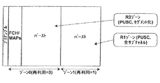
(viii)FFR管理部
図11は、分割周波数再利用(FFR)に対応するDLサブフレームの構成を示す。「リユース3」と「リユース1」ゾーンとの間のゾーン切り替え点が図11に示すようにネットワーク全体を通じて調整され、それによりサブフレーム決定部がネットワーク管理エンティティと連動してリユース3とリユース1のゾーン遷移点を設定することが期待される。FFR管理部の役割は、局管理部のゾーン割り当て機能により用いられる閾を最適に選択し、MSが「R3」又は「R1」ゾーンのどちらに割り当てられたかを決定することである。これは、システムが図11に示すような最適な動作領域で動作することを可能にする。ゾーン割り当てアルゴリズム及び閾計算アルゴリズムに関する更なる詳細を以下に説明する。
(Viii) FFR management unit FIG. 11 illustrates a configuration of a DL subframe corresponding to division frequency reuse (FFR). The zone switching point between the “
<PDU生成部のLMACスケジューリングの構成要素の説明>
WiMAXのBSスケジューラ及びPDU生成部の主要な構成要素を以下に詳細に説明する。
<Description of components of LMAC scheduling of PDU generation unit>
The main components of the WiMAX BS scheduler and PDU generator will be described in detail below.
(a)局管理部
局管理部は、3つの機能及び多数のデータ構造を有する。これらを以下の区分に分けて説明する。
(A) Station management unit The station management unit has three functions and a number of data structures. These will be described in the following categories.
(a1)MS状態データ構造
この構造は、MSに特有であるがMSのコネクション(又はサービス・フロー)の全てに適用されるパラメータの現在の状態を維持する。パラメータを以下に示す。
MS状態データ構造は、アクティブなコネクション毎にCID状態オブジェクトも有する。 The MS state data structure also has a CID state object for each active connection.
BS及びMSのPHY層は、物理CINRレポートのみに対応してもよく(Wave1)、追加で実効CINRレポートに対応してもよい(Wave2)。MS状態データ構造は、物理CINRだけでなく、物理CINR測定値又は実効CINR測定値のどちらかを有するよう拡張されうる。 The BS and MS PHY layers may support only physical CINR reports (Wave1) or may additionally support effective CINR reports (Wave2). The MS state data structure can be extended to have either physical CINR measurements or effective CINR measurements, as well as physical CINRs.
(a2)CID状態データ構造
このデータ構造は、MSのコネクション(又はサービス・フロー)に特有なパラメータの現在の状態を維持するために用いられる。パラメータを以下に示す。
最大許容SDU待ち時間(Maximum Allowed SDU Latency)は、QoSパラメータ・セットの中に設定された最大待ち時間(Maximum latency)に基づき計算される。最大待ち時間(Maximum latency)はCSピア・ツー・ピアの待ち時間である。従って、最大許容SDU待ち時間(Maximum Allowed SDU Latency)はSDUのスケジューリングとCSピアでの到着との間の特別遅延を考慮に入れる必要がある。局管理部は、最大許容SDU待ち時間(Maximum Allowed SDU Latency)のこの計算を行う。 Maximum Allowed SDU Latency is calculated based on the Maximum Latency set in the QoS parameter set. Maximum latency is the CS peer-to-peer latency. Therefore, the Maximum Allowed SDU Latency needs to take into account the special delay between SDU scheduling and arrival at the CS peer. The station manager performs this calculation of the maximum allowed SDU latency.
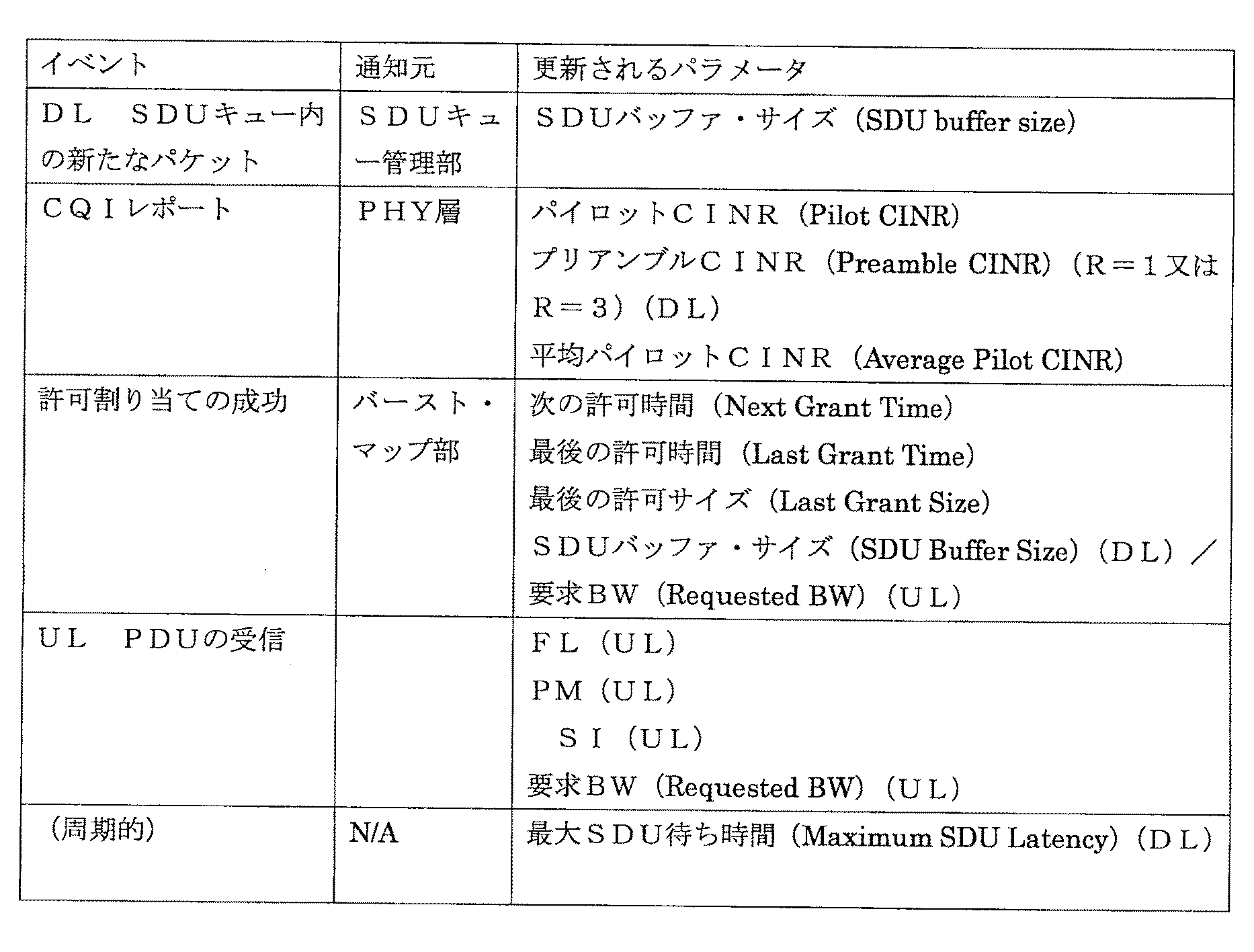
(a3)MS/CID状態更新
本機能は、MS状態(MS Status)及び関連するCID状態(CID Status)のデータ構造をイベントに基づき更新する。更新を生じさせるイベントを以下に示す。
(a4)CQIレポート・イベント
パイロットCINRについてのCQIレポートが受信されると、平均パイロットCINR(Average Pilot CINR)が更新される。更新に用いられる式を次に示す。
比例公平アルゴリズムにより用いられる平均CINRが適切であることを保証することを目的として、βの最適な設定に達するためにシミュレーションを用いる。平均ウインドウが長すぎる場合、比例公平アルゴリズムはラウンドロビンのようになり、如何なるスペクトル効率の利益も提供しない。一方で、平均ウインドウが短すぎる場合、比例公平アルゴリズムは最大C/Iのようになり、如何なる公平さも提供しない。 In order to ensure that the average CINR used by the proportional fair algorithm is adequate, a simulation is used to reach the optimal setting of β. If the average window is too long, the proportional fair algorithm looks like round robin and does not provide any spectral efficiency benefits. On the other hand, if the average window is too short, the proportional fair algorithm will be at maximum C / I and will not provide any fairness.
(a5)許可/ポーリング割り当ての成功イベント
許可の成功の場合には、最後の許可時間(Last Grant Time)は現在時刻に等しく設定される。SDUバッファ・サイズ(SDU Buffer Size)又は要求BW(Requested BW)は割り当てられたSDUバイト数だけ減じられる。サービスが設定されたアンソリシテッド・グラント・インターバル(Unsolicited grant interval)を有する場合、次の許可時間(Next Grant Time)が現在時刻とアンソリシテッド・グラント・インターバルの和に基づき設定される。最後に、サービスが設定された次のポーリング時間(Next Poll Time)を有する場合、該次のポーリング時間が現在時刻とアンソリシテッド・ポーリング・インターバル(Unsolicited Polling Interval)の和に基づき設定される。ポーリング割り当ての成功の場合には、次のポーリング時間(Next Poll Time)は現在時刻とアンソリシテッド・ポーリング・インターバルの和に等しく設定される。
(A5) Success event of grant / polling assignment When the grant is successful, the last grant time is set equal to the current time. The SDU Buffer Size or Requested BW is reduced by the number of allocated SDU bytes. If the service has a set Unsolicited grant interval, the next grant time is set based on the sum of the current time and the unsolicited grant interval. Finally, when the service has a set next polling time (Next Poll Time), the next polling time is set based on the sum of the current time and the unsolicited polling interval (Unsolicited Polling Interval). If the polling assignment is successful, the next polling time (Next Poll Time) is set equal to the sum of the current time and the unsolicited polling interval.
(a6)ゾーン配置(FFR)
プリアンブルCINRレポートが受信されたときは常に、ゾーン割り当て機能がMS/CID更新機能により呼び出される。ゾーン割り当て機能の動作は、MSがリユース1又はリユース3のゾーン内に配置されているかに依存する。
(A6) Zone arrangement (FFR)
Whenever a preamble CINR report is received, the zone assignment function is invoked by the MS / CID update function. The operation of the zone assignment function depends on whether the MS is located in the
ここでは、CINR1は再利用構成1のためにプリアンブルに対して行われたCINR測定値を表すために用いられる。またCINR3は再利用構成3のためにプリアンブルに対して行われたCINR測定値を表す。
Here, CINR1 is used to represent the CINR measurement performed on the preamble for
(a7)リユース3の動作
MSがリユース3ゾーンに現在割り当てられている場合、ゾーン割り当て機能は、CINR1リポートがR1/R3遷移閾より上かどうかを調べる。閾より上の場合、ゾーン割り当て機能は、CIDをR1ゾーンに割り当てる。閾より上でない場合、コネクションはR3ゾーンのままである。次に、ゾーン割り当て機能は、PHY層をスケジューリングし、CINR1の次の周期的チェックを実行する。
(A7) Operation of
(a8)リユース1の動作(CINR1レポートの受信)
リユース1ゾーンの場合、ゾーン割り当て機能は、CINR1リポートがR1/R3遷移閾より下かどうかを調べる。閾より下の場合、ゾーン割り当て機能は、CINR3の測定値を要求する。閾より下でない場合、コネクションはR1ゾーンのままである。次に、ゾーン割り当て機能は、PHY層をスケジューリングし、CINR1の次の周期的チェックを実行する。
(A8) Operation of reuse 1 (reception of CINR1 report)
In the case of a
(a9)リユース1の動作(CINR3レポートの受信)
CINR3レポートがCINR1レポートより高い場合、ゾーン割り当て機能は、CIDをR3ゾーンに割り当てる。次に、ゾーン割り当て機能は、PHY層をスケジューリングし、CINR1の次の周期的チェックを実行する。レポートを得る1つの可能性は、CINR1レポートのためにCQICHを介して周期的CQIレポートを設定することである。次に、REP−REQ/RSPは、要求に応じてCINR3レポートを得るために利用されうる。
(A9) Operation of reuse 1 (reception of CINR3 report)
If the CINR3 report is higher than the CINR1 report, the zone assignment function assigns a CID to the R3 zone. The zone assignment function then schedules the PHY layer and performs the next periodic check of CINR1. One possibility to obtain a report is to set up a periodic CQI report via CQICH for the CINR1 report. The REP-REQ / RSP can then be used to obtain a CINR3 report on demand.
(a10)バースト・プロファイル割り当て
パイロットCQIレポートが受信されたときは常に、バースト・プロファイル割り当て機能がMS/MS/CID更新機能により開始され、MSコネクションのために適正なバースト・プロファイル割り当てを行うことを保証する。Wave1ではMSはパイロット・サブキャリアについての物理CINR測定のみに対応しているので、バースト・プロファイル割り当てアルゴリズムはこのメトリックを利用する。
バースト・プロファイル割り当て機能は、物理CINRの検索テーブルの使用に基づき、アクティブなバースト・プロファイルのリストから最適なバースト・プロファイル・フォーマットを定める。バースト・プロファイルのCINRへのマッピングがチャネル・タイプと共に変化することが期待されるので、多数の検索テーブルが必要とされるだろう。
(A10) Burst profile assignment Whenever a pilot CQI report is received, the burst profile assignment function is initiated by the MS / MS / CID update function to ensure proper burst profile assignment for the MS connection. Guarantee. In Wave1, the MS only supports physical CINR measurements for pilot subcarriers, so the burst profile assignment algorithm uses this metric.
The burst profile assignment function determines the optimal burst profile format from the list of active burst profiles based on the use of a physical CINR lookup table. Since the mapping of burst profiles to CINR is expected to change with channel type, a large number of lookup tables will be required.
(b)FFR管理部
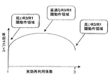
FFR管理部の役割は、システムのスペクトル効率を最大化することである。一般に、図11に示すように、システムの効果的なスペクトル効率は実効再利用係数と共に変化すると期待される。
(B) FFR management unit The role of the FFR management unit is to maximize the spectral efficiency of the system. In general, as shown in FIG. 11, the effective spectral efficiency of the system is expected to change with the effective reuse factor.
通常、IEEE802.16システムのOFDMAフレームは、リユース3ゾーンから開始する。これは、リユース3ゾーンがフレームのプリアンブルのための伝送モードとして定められているからである(図3及び10を参照)。FFR管理部は、局管理部内のゾーン割り当て機能により用いられる最適なR3/R1(リユース3/リユース1)遷移CINRを選択し、OTA(over-the-air)スループット(つまり、PHY層へ送信されるペイロードのビット数)を最大化することによりスペクトル効率を最大化するようにする。
Normally, the OFDMA frame of the IEEE 802.16 system starts from the
閾が低すぎる場合、全てのユーザはリユース1ゾーンになる。干渉は、セクタ端周辺の何人かのユーザに生じ、CINRを低下させる。これにより、バースト・プロファイルは非常に強靱に設定され、結果としてスループットが低下する。反対に、閾が高すぎる場合、全てのユーザはリユース3ゾーンになる。これは全てのユーザにリンク・レベルで最良のスループットを保証するが、割り当てに利用可能なスロット数は、前者の場合に利用可能なスロット数の3分の1である。従って、システムのスループットは妥協される。従って、OTAの閾を調整の影響を監視すること及び単純な傾斜降下に基づくアルゴリズムを用いることにより、FFR管理部が遷移点を最適に調整することが可能になる。
If the threshold is too low, all users are in the
(c)コネクション・スケジューラ
QoS要件が確実に満たされるために、コネクション・スケジューラは、UGSサービス・タイプに割り当てられたコネクションを考慮することから開始し、次にリアルタイム、拡張リアルタイム、非リアルタイムのサービス・タイプに割り当てられたコネクションへ進み、最後にベストエフォート・サービス・タイプへ進む。
(C) Connection scheduler To ensure that QoS requirements are met, the connection scheduler starts by considering the connections assigned to the UGS service type, and then the real-time, extended real-time, non-real-time service Go to the connection assigned to the type, and finally go to the best effort service type.
サービス・タイプ毎に、コネクション・スケジューラは、QoSパラメータ・セットに対して現在のQoSメトリック(Current QoS Metrics)を分析することにより、コネクションがフレーム内でスケジューリングされるべきかどうかを決定する必要がある。サービス・タイプ毎にこれを決定するアルゴリズムを以下で検討する。本説明は、先ず下り回線コネクション・スケジューラに焦点を当て、上り回線コネクション・スケジューラの場合との相違を強調する。 For each service type, the connection scheduler needs to determine whether the connection should be scheduled in a frame by analyzing the current QoS Metrics against the QoS parameter set. . The algorithm for determining this for each service type is discussed below. This description first focuses on the downlink connection scheduler and highlights the differences from the case of the uplink connection scheduler.
コネクション・スケジューラが、フレーム内でコネクションをスケジューリングする必要がないが、利用可能なリソースが存在するならば該コネクションに帯域幅を許可しうると決定した場合、残りのコネクションの要件が検討されるまで、該コネクションは保留される。該コネクションが他の全ての後に検討されるべきか否かを決定する方法に関する詳細を以下に説明する。 If the connection scheduler does not need to schedule a connection in a frame but decides that it can allow bandwidth if there are available resources, until the requirements for the remaining connections are considered The connection is suspended. Details regarding how to determine whether the connection should be considered after all others are described below.
留意すべき点は、DLの全てのコネクションでは、該コネクションのSDUバッファ・サイズ(SDU Buffer Size)がゼロであるか又は該コネクションがスリープ状態であり現在のフレームが傾聴ウインドウではなく、従って該コネクションがスケジューリングされないことである。同様に、ULでは、要求BW(Requested BW)がゼロであり且つコネクションがアンソリシテッド・グラント若しくはポーリングを発行されない又はDL用に記述された同一のスリープ条件が存在する場合、コネクションはスケジューリングされない。 Note that for all DL connections, the connection's SDU Buffer Size is zero or the connection is sleeping and the current frame is not a listening window, so the connection Is not scheduled. Similarly, in UL, if the Requested BW is zero and the connection is not issued an unsolicited grant or poll, or there is an identical sleep condition described for the DL, the connection is not scheduled.
ERT、NRT又はBEコネクションで受信される競合型のCDMA帯域幅要求の場合には、リソースの予約とCDMA_Allocation_IEのUL MAPへの挿入は、コネクション・スケジューラとは別個に解決される。CDMA_Allocation_IEのためのリソース割り当ては、バースト・マップ部がスケジューリングされたコネクションにリソースを割り当てる前に行われる。留意すべき点は、フレーム当たりの最大コネクション数も、MAC層のリソース限界に従って設定されることである。 In the case of contention-type CDMA bandwidth requests received over ERT, NRT or BE connections, resource reservation and insertion of CDMA_Allocation_IE into the UL MAP are resolved separately from the connection scheduler. Resource allocation for CDMA_Allocation_IE is performed before the burst map unit allocates resources to the scheduled connection. It should be noted that the maximum number of connections per frame is also set according to the resource limit of the MAC layer.
コネクション・スケジューラは、冒頭で概略を説明した種々のサービス・クラスのコネクションを以下のように処理する。 The connection scheduler processes connections of various service classes outlined at the beginning as follows.
(c1)UGS
UGSサービス・タイプに割り当てられたコネクションは、コネクションをスケジューリングするか否かの決定に関連する以下のQoSパラメータを設定される。
−許容ジッタ(Tolerated jitter)
−最大待ち時間(Maximum latency)
−要求/伝送ポリシー(Request/Transmission policy)
−アンソリシテッド・グラント・インターバル(Unsolicited grant interval)
コネクション・スケジューラは、次の許可時間(Next Grant Time)がサブフレーム内か(又は期限切れか)又はコネクションがフレーム内にスケジューリングされていない場合に最大許容SDU待ち時間(Maximum Allowed SDU Latency)を超過しているかを調べる。結果が肯定的な場合、コネクションをそのフレーム内でスケジューリングすることが検討される。これらのイベントの何れも生じない場合、コネクションは現行フレーム内にスケジューリングされない。
(C1) UGS
A connection assigned to a UGS service type is set with the following QoS parameters related to determining whether to schedule the connection.
-Tolerated jitter
-Maximum latency
-Request / Transmission policy
-Unsolicited grant interval
The connection scheduler exceeds the Maximum Allowed SDU Latency if the Next Grant Time is in a subframe (or expires) or if the connection is not scheduled in the frame. Find out. If the result is positive, consider scheduling the connection within that frame. If none of these events occur, the connection is not scheduled in the current frame.
全てのUGSコネクションの検討が終了すると、現行フレームにスケジューリングされたコネクションは、以下に示す最後の許可時間(Latest Grant Time)に基づきランク付けされる。
Latest Grant Time=min(Next Grant Interval+Tolerated jitter,Next Grant Interval+Max.Allowed SDU Latency-Current Max.SDU Latency)
ランク付けは、最後の許可時間(Latest Grant Time)の昇順である。
When all UGS connections have been considered, the connections scheduled in the current frame are ranked based on the last grant time shown below.
Latest Grant Time = min (Next Grant Interval + Tolerated jitter, Next Grant Interval + Max.Allowed SDU Latency-Current Max.SDU Latency)
Ranking is in ascending order of last grant time.
ULの場合、SDU待ち時間は、CID状態の中のFLフィールドを介して得られる。FLが最大許容SDU待ち時間(Max Allowed SDU Latency)と等しいか又はそれより大きい場合、コネクションはそのフレーム内にスケジューリングされる。 For UL, SDU latency is obtained via the FL field in the CID state. If the FL is equal to or greater than the Max Allowed SDU Latency, the connection is scheduled in that frame.
(c2)リアルタイム(RT)サービス
RTサービス・タイプに割り当てられたコネクションは、コネクションをスケジューリングするか否かの決定に関連する以下のQoSパラメータを設定される。
−最大待ち時間(Maximum latency)
−最低保証トラフィック・レート(Minimum reserved traffic rate)
コネクション・スケジューラは、コネクションがそのフレーム内にスケジューリングされていない場合に、SDU待ち時間(SDU Latency)を超過しているか(つまり、Maximum Allowed SDU Latency−Current Maximum SDU Latency<フレーム期間か)を調べる。結果が肯定的な場合、コネクションをそのフレーム内でスケジューリングすることが検討される。また、コネクションがそのフレーム内にスケジューリングされていない場合、次式を用いて現在の最小レート(Current Minimum Rate)を計算することにより、最低保証トラフィック・レートが満たされるかも調べる。
Current Minimum Rate=Last Grant Size/(Next Frame Time-Last Grant Time)
Current Minimum Rate<Minimum reserved traffic rateの場合に、コネクションがスケジューリングされる。いずれの条件も満たされない場合、残りのサービス・クラスの検討が終了した後に、コネクションは再検討される。ULの場合には、BSは、アンソリシテッド・ポーリング・インターバル(Unsolicited Polling Interval)に基づき定期的なポーリング機会を提供する必要がある。これに対応するため、次のポーリング時間(Next Poll Time)がそのフレーム内にスケジューリングされた(又は期限切れの)場合、コネクション・スケジューラはコネクションをスケジューリングする。BSも、ULの場合と同様に、最低保証トラフィック・レート(Minimum reserved traffic rate)が満たされることを保証する必要がある。従って、ULでも、Current Minimum Rate<Minimum reserved traffic rateの場合に、コネクションがスケジューリングされる。
(C2) Real-Time (RT) Service Connections assigned to the RT service type are set with the following QoS parameters related to determining whether to schedule the connection.
-Maximum latency
-Minimum reserved traffic rate
If the connection is not scheduled in the frame, the connection scheduler checks whether the SDU latency (SDU Latency) has been exceeded (that is, Maximum Allowed SDU Latency−Current Maximum SDU Latency <frame duration). If the result is positive, consider scheduling the connection within that frame. Also, if the connection is not scheduled in the frame, it is also checked whether the minimum guaranteed traffic rate is met by calculating the current minimum rate using the following equation:
Current Minimum Rate = Last Grant Size / (Next Frame Time-Last Grant Time)
A connection is scheduled when Current Minimum Rate <Minimum reserved traffic rate. If neither condition is met, the connection is reconsidered after the remaining service classes have been considered. In the case of UL, the BS needs to provide periodic polling opportunities based on the Unsolicited Polling Interval. To accommodate this, if the next poll time is scheduled (or expired) within the frame, the connection scheduler schedules the connection. The BS needs to ensure that the minimum reserved traffic rate is satisfied as in the case of UL. Therefore, even in UL, a connection is scheduled when Current Minimum Rate <Minimum reserved traffic rate.
(c3)拡張リアルタイム(ERT)サービス
ERTサービス・タイプに割り当てられたコネクションは、コネクションをスケジューリングするか否かの決定に関連する以下のQoSパラメータを設定される。
−最大待ち時間(Maximum latency)
−許容ジッタ(Tolerated jitter)
−最低保証トラフィック・レート(Minimum reserved traffic rate)
−アンソリシテッド・グラント・インターバル(Unsolicited grant interval)
UGS及びRTについて上述したのと同一のメカニズムを用い、許可インターバル、待ち時間及び最低レートに基づき、コネクションをスケジューリングするかを決定する。更に、選択したコネクションは、UGSに用いられる基準に基づきランク付けされる。条件の何れも満たされない場合、コネクションはそのフレーム内にスケジューリングされない。
(C3) Extended Real Time (ERT) Service Connections assigned to an ERT service type are set with the following QoS parameters related to determining whether to schedule a connection.
-Maximum latency
-Tolerated jitter
-Minimum reserved traffic rate
-Unsolicited grant interval
The same mechanism as described above for UGS and RT is used to determine whether to schedule the connection based on the grant interval, latency and minimum rate. In addition, the selected connections are ranked based on the criteria used for UGS. If none of the conditions are met, the connection is not scheduled in that frame.
ULの場合には、コネクション・スケジューラは、UGS及びRTについて上述したのと同一のメカニズムを用い、インターバル又はレートに基づきコネクションをスケジューリングするかどうか決定する。留意すべき点は、ULの場合には、ERTはポーリング機会を提供せず、常に許可を与えることである。許可は追加の帯域幅を要求するために用いられる。 In the case of UL, the connection scheduler uses the same mechanism as described above for UGS and RT and decides whether to schedule the connection based on the interval or rate. It should be noted that in the case of UL, ERT does not provide a polling opportunity and always grants permission. Grants are used to request additional bandwidth.
(c4)非リアルタイム(NRT)サービス
NRTサービス・タイプに割り当てられたコネクションは、コネクションをスケジューリングするか否かの決定に関連する以下のQoSパラメータを設定される。
−最低保証トラフィック・レート(Minimum reserved traffic rate)
RTの場合と同一のメカニズムが用い、コネクションを最低レート保証に基づきスケジューリングするかどうかを決定する。条件が満たされない場合、残りのサービス・クラスの検討が終了した後に、コネクションは再検討される。ULでは、コネクション・スケジューラはポ―リング機会を提供するが、ポーリングのレートは1秒程度である。従って、ULの場合には、コネクションは要求に応じてスケジューリングされ、最低レートの要件又は次のポーリング時間が満たされること(若しくは期限切れ)を保証する。
(C4) Non-real-time (NRT) service A connection assigned to an NRT service type is set with the following QoS parameters related to determining whether to schedule the connection.
-Minimum reserved traffic rate
The same mechanism as in RT is used to determine whether to schedule a connection based on a minimum rate guarantee. If the condition is not met, the connection is reconsidered after the remaining service classes have been considered. In UL, the connection scheduler provides polling opportunities, but the polling rate is on the order of 1 second. Thus, in the case of UL, the connection is scheduled on demand to ensure that the minimum rate requirement or the next polling time is met (or expires).
(c5)ベストエフォート(BE)サービス
BEに割り当てられたコネクション並びにRT及びNRTに割り当てられた、QoSの要求を満たすためにスケジューリングされなかったコネクションが最後に検討される。前述のメカニズムは結果として最低QoS要求を満たすようリソースを割り当てるので、残りのリソースは、スペクトル効率を最大化すると同時に、残りのリソースの部分の割り当てをある程公平に度維持するように割り当てられる。
(C5) Best effort (BE) service Connections assigned to BE and connections assigned to RT and NRT that have not been scheduled to meet QoS requirements are considered last. As the above mechanism results in allocating resources to meet the minimum QoS requirements, the remaining resources are allocated to maximize the spectral efficiency while maintaining a fairly fair allocation of the remaining resource portions.
これを行う前に、コネクション・スケジューラは、以上にサービス・クラスと関連して概要を説明したメカニズムによってスケジューリングされた全てのRT及びNRTコネクションを、残りのコネクションのリストに追加する。これは、最初にQoSを保証するために必要な最低リソースを割り当てるPDU形成部の動作を支援することである。これが行われると、コネクション・スケジューラは、残りのリソースを割り当ててスペクトル効率を最大化する。従って、既に最小値を割り当てられたRT及びNRTコネクションは、スケジューリングされていないコネクションが検討されるのと同一の方法で、許可サイズを増大させるために再検討されうる。 Before doing this, the connection scheduler adds to the list of remaining connections all RT and NRT connections scheduled by the mechanism outlined above in connection with the service class. This is to support the operation of the PDU formation unit that allocates the minimum resources necessary to guarantee QoS first. When this is done, the connection scheduler allocates the remaining resources to maximize spectral efficiency. Thus, RT and NRT connections that have already been assigned a minimum value can be reviewed to increase the grant size in the same way that unscheduled connections are considered.
次に、コネクションのリストは、例えば均等に公平な基準を用いて格納される。最初の段階は、リストiの中の各コネクションに対しコネクションの重みを計算することである。
Wi=Last recorded CINR/(Averaged CINR)
次に、コネクションはWiの降順に格納される。多くのコネクションの重みが同一の範囲内にある場合に公平さを維持することを保証するために、コネクション・スケジューラは最後の許可時間(Last Grant Time)に基づきこれらのコネクションのリストを任意的にソートする。ULでは、同一のメカニズムを用い、残りのコネクションをスケジューリングするか否かを決定する。
Next, the list of connections is stored using, for example, an equally fair standard. The first step is to calculate the connection weight for each connection in list i.
Wi = Last recorded CINR / (Averaged CINR)
Next, the connections are stored in descending order of Wi. To ensure that fairness is maintained when many connection weights are within the same range, the connection scheduler can optionally list these connections based on the last grant time. Sort. In UL, the same mechanism is used to determine whether to schedule the remaining connections.
上述のスケジューリングされていないコネクションをソートするメカニズムは、特定の用途に好適なように、システム・オペレータにより置き換えられてよい(又は該メカニズムの基準を変更されてよい)。 The mechanism for sorting unscheduled connections described above may be replaced by the system operator (or the criteria for the mechanism may be changed) as appropriate for the particular application.
(c6)他のタスク
各サービス・タイプが検討されると、コネクション記述子(Connection Descriptors)のリストが構築される。これは順序付けられたリストであり、最上位のUGSコネクションの記述子で開始し、厳格な順序でRT、ERT、NRTコネクションの記述子が続く。次に、格納されたBEコネクションのリストがコネクション記述子のリストに追加され、サブフレーム形成部へ供給されるコネクション記述子の完全なリストを形成する。ところで、あるシステムでは、順序付けられたリストの中でERTをRTより優先して扱うことが望ましい。
(C6) Other tasks As each service type is considered, a list of connection descriptors is constructed. This is an ordered list, starting with the descriptor for the top-level UGS connection, followed by the descriptors for RT, ERT, and NRT connections in strict order. Next, the stored list of BE connections is added to the list of connection descriptors to form a complete list of connection descriptors supplied to the subframe forming unit. By the way, in a certain system, it is desirable to handle ERT in preference to RT in an ordered list.
コネクション記述子(Connection Descriptors)は、以下の情報を有する。
−CID状態(CID Status)へのポインタ(従って、パラメータがアクセスされうる。)
−スケジューリングの理由:許可インターバル(Grant Interval)、待ち時間(Latency)、最低レート(Min Rate)、なし、(ULでのポーリング)。
The connection descriptor (Connection Descriptors) has the following information.
A pointer to the CID status (thus the parameter can be accessed)
Reason for scheduling: Grant Interval, Latency, Min Rate, None, (UL polling).
アルゴリズムはQoSパラメータ・セット内のサービス・タイプ(Service Type)及びスケジューリングの理由に依存するので、スケジューリングの理由は、そのCIDの許可サイズ(Grant Size)を計算するために用いる方法を決定するためにバースト・マップ部により用いられる(更なる詳細は以下の「バースト・マップ部」の個所で説明する)。理由「なし」は、フレーム内のコネクションのスケジューリングを生じさせる如何なる最低QoS要件も存在しないことを示す。 Since the algorithm depends on the service type in the QoS parameter set and the reason for scheduling, the reason for scheduling is to determine the method used to calculate the Grant Size for that CID. Used by the burst map section (further details are given in the section “Burst Map Section” below). The reason “none” indicates that there is no minimum QoS requirement that causes scheduling of connections in the frame.
(d)バースト・マップ部
バースト・マップ部は、コネクション・スケジューラにより供給されたコネクション記述子(Connection Descriptors)のリストを順々に捜索する。割り当てられPDU形成部に送信されたPDUサイズに到達しMAP IEを更新(又はULの場合には生成)するために、バースト・マップ部は以下のアルゴリズムをコネクション毎に実行する。
1 (割り当てられたバースト・プロファイルを有するバースト用に割り当てられたゾーン内の捜索に基づき)コネクションのための対象バーストの位置を決める。(注意:バースト当たり256個のコネクションの制限が守られなければならない。)
2 バーストが見付かると、スロット内の最大残りリソースを決定する。
3 利用可能なスロット及び割り当てられたバースト・プロファイル・フォーマットに基づき、最大許容PDU割り当てを計算する。
4 適切なアルゴリズムを用い、(以下に説明するように)サービス・クラスに基づき実際のPDUサイズを決定する。留意すべき点は、割り当てられたサイズがSDUバッファ内に残っているSDUの量又は対象バースト内で利用可能なリソースの量の最小値を決して超えないことである。ULの場合には、非UGSコネクションの場合に要求されたBWの量を超えない(留意すべき点は、割り当てがポーリングのためである場合には、如何なる要求されたBWも突出していないので、割り当ては6バイトになることである)。また、バースト・サイズは、フラグメント化及び/又はパッキングを防ぎうるのでコネクションのために設定された要求/伝送ポリシーを考慮しなければならない。この場合には、バースト・マップ部は、次のSDUのサイズを決定し、これを用いて割り当てサイズを制限しなければならない。
(D) Burst map section The burst map section sequentially searches a list of connection descriptors (Connection Descriptors) supplied by the connection scheduler. In order to reach the PDU size allocated and transmitted to the PDU formation unit and update the MAP IE (or generate in the case of UL), the burst map unit executes the following algorithm for each connection.
1 Determine the location of the burst of interest for the connection (based on a search within the zone assigned for the burst with the assigned burst profile). (Note: The limit of 256 connections per burst must be observed.)
2 If a burst is found, determine the maximum remaining resource in the slot.
3. Calculate the maximum allowed PDU allocation based on the available slots and the assigned burst profile format.
4 Use an appropriate algorithm to determine the actual PDU size based on the service class (as described below). It should be noted that the allocated size never exceeds the minimum amount of SDU remaining in the SDU buffer or the amount of resources available in the target burst. In the case of UL, it does not exceed the amount of BW requested for non-UGS connections (note that if the allocation is for polling, no requested BW will protrude) The allocation is to be 6 bytes). Also, the burst size must take into account the request / transmission policy set for the connection as it can prevent fragmentation and / or packing. In this case, the burst map unit must determine the size of the next SDU and use this to limit the allocation size.
許可サイズ(Grant Size)がコネクション毎に決定されると、MAPメッセージは適切に更新される。DLでは、バーストを記述するIEは、コネクションのCIDを含むように更新される。ULでは、このコネクションがスケジューリングされた最初のコネクションである場合に、IEはUL MAPに挿入される。このコネクションがスケジューリングされた更なるコネクションである場合には、IEに記録された割り当てサイズは、(ULではMS当たり1つのIEしかないので)許可サイズ(Grant Size)だけ増加される。上述の終了条件のいずれも満たされない場合、バースト・マップ部は、コネクション記述子(Connection Descriptors)のリストの処理を終了する。より詳細には、バースト・マップ部は以下のように異なるサービス・クラスのコネクションを処理する。 When the grant size is determined for each connection, the MAP message is updated appropriately. In DL, the IE describing the burst is updated to include the CID of the connection. In the UL, the IE is inserted into the UL MAP when this connection is the first scheduled connection. If this connection is a scheduled further connection, the allocation size recorded in the IE is increased by the Grant Size (since there is only one IE per MS in the UL). If none of the above termination conditions is satisfied, the burst map unit terminates the processing of the list of connection descriptors (Connection Descriptors). More specifically, the burst map unit handles connections of different service classes as follows.
(d1)UGS
UGSコネクションは、その許可インターバル又はSDU待ち時間を超過しそうであることを理由にスケジューリングされている。前者の理由の場合には、許可サイズ(Grant Size)は最大持続的トラフィック・レート(Maximum sustained traffic rate)(最小値に等しい)及びアンソリシテッド・グラント・インターバル(Unsolicited grant interval)から計算されうる。
Grant Size=Traffic Rate*Unsolicited grant interval
後者の理由でコネクションがスケジューリングされた場合、許可サイズ(Grant Size)は待ち時間の要件を超過しそうなSDUに含まれているデータの量(つまり、最大遅延を経験するSDU内のバイト数(Number of Bytes in SDUs Experiencing Maximum Delay)のサイズとパッキングに対応するために必要なサブヘッダの和)(複数のSDUがスケジューリングされる場合には、最大遅延を経験するSDUの数(Number of SDUs Experiencing Maximum Delay)の値)と等しい。
(D1) UGS
A UGS connection is scheduled because it is likely to exceed its grant interval or SDU latency. For the former reason, the Grant Size can be calculated from the Maximum sustained traffic rate (equal to the minimum value) and the Unsolicited grant interval.
Grant Size = Traffic Rate * Unsolicited grant interval
If the connection is scheduled for the latter reason, the Grant Size is the amount of data contained in the SDU that is likely to exceed the latency requirement (ie, the number of bytes in the SDU experiencing the maximum delay) of Bytes in SDUs Experiencing Maximum Delay) and the sum of the sub-headers needed to accommodate the packing) (Number of SDUs Experiencing Maximum Delay if multiple SDUs are scheduled) ) Value)).
選択したバーストがこのサイズの許可に対応できない場合、バースト・マップ部は、割り当てが行われうる別の適切なバーストの位置を決めようと試みる。如何なるバーストも見付からない場合、許可サイズ(Grant Size)は、全ての可能な対象バースト内で見付かった最も大きい最大許容PDUサイズに合うように調整される。ULの場合、同一の方法が用いられる。しかしながら、SIビットがCID状態(CID Status)内に設定されている場合、BSは許可サイズ(Grant Size)の101%を割り当てることにより過剰に割り当てる。 If the selected burst cannot accommodate this size grant, the burst map section attempts to locate another suitable burst at which an assignment can be made. If no burst is found, the Grant Size is adjusted to match the largest maximum allowed PDU size found in all possible target bursts. In the case of UL, the same method is used. However, if the SI bit is set in the CID status, the BS allocates excessively by allocating 101% of the grant size.
(d2)リアルタイム(RT)サービス
RTコネクションは、そのSDU待ち時間を超過しそうであること又は最低保証レートが満たされないことを理由にスケジューリングされている。前者の理由である場合、許可サイズ(Grant Size)は上述と同様に計算される。後者の理由である場合、サイズは最低及び最大レートの要件を満たすことを保証する必要がある。従って、許可は以下により区切られる。
Minimum reserved traffic rate*(現在時刻−Last Grant Time)<Grant Size<Max Sustained Traffic Rate*(現在時刻−Last Grant Time)
先ず最低QoS要件を維持するために、この段階で、許可サイズ(Grant Size)が設定され、最低保証トラフィック・レート(Minimum reserved traffic rate)の要件を満たすことを保証する。次に、残りのサービス・タイプが更なる帯域幅の割り当てのために検討された後に、コネクションが再び検討される。ULでは、コネクションは、最低保証トラフィック・レート(Minimum reserved traffic rate)が満たされない又はアンソリシテッド・ポーリング・インターバル(Unsolicited Polling Interval)が終了することを理由にスケジューリングされている。前者の場合、同一の方法を利用して、許可サイズを計算する。後者の場合、許可サイズ(Grant Size)は、(BW要求ヘッダ(BW Request Header)を送信可能にするため)6バイトに等しく設定される。留意すべき点は、追加のBWはBEサービスの場合に以下に説明するメカニズムで割り当てられてよい。
(D2) Real-time (RT) service RT connections are scheduled because they are likely to exceed their SDU latency or the minimum guaranteed rate is not met. In the former reason, the grant size is calculated in the same manner as described above. For the latter reason, the size needs to be guaranteed to meet the minimum and maximum rate requirements. Thus, permissions are delimited by:
Minimum reserved traffic rate * (current time-Last Grant Time) <Grant Size <Max Sustained Traffic Rate * (current time-Last Grant Time)
First, in order to maintain the minimum QoS requirement, a grant size is set at this stage to ensure that the minimum reserved traffic rate requirement is met. The connection is then considered again after the remaining service types are considered for further bandwidth allocation. In UL, a connection is scheduled because the Minimum reserved traffic rate is not met or because the Unsolicited Polling Interval ends. In the former case, the permitted size is calculated using the same method. In the latter case, the grant size (Grant Size) is set equal to 6 bytes (to allow transmission of the BW Request Header). It should be noted that additional BWs may be assigned with the mechanism described below in the case of BE services.
(d3)拡張リアルタイム(ERT)サービス
ERTコネクションは、その許可インターバル、SDU待ち時間を超過しそうであること又は最低保証レートが満たされないことを理由にスケジューリングされている。最初の2つの場合のいずれかの場合には、UGSの場合に説明したメカニズムを利用して許可サイズを計算し、その他の場合にはRTについてのレートのためのメカニズムを利用する。
(D3) Enhanced Real Time (ERT) Service The ERT connection is scheduled because its grant interval, SDU latency is likely to be exceeded, or the minimum guaranteed rate is not met. In either of the first two cases, the grant size is calculated using the mechanism described for the UGS case, otherwise the rate mechanism for RT is used.
ULの場合には、ERTコネクションは、許可インターバル又は最低レートの要件によりスケジューリングされる。ULの場合にUGS及びRTについて既に説明した適切なメカニズムが利用される。 In the case of UL, ERT connections are scheduled according to grant interval or minimum rate requirements. In the case of UL, the appropriate mechanisms already described for UGS and RT are used.
(d4)非リアルタイム(NRT)サービス
NRTコネクションは、スケジューリングされていない限り、最低保証レートが満たされないことを理由にスケジューリングされている。従って、許可サイズ(Grant Size)は以下により計算される。
Grant Size=Minimum reserved traffic rate*(現在時刻−Last Grant Time)
ULでは、最低保証レートの要件によりスケジューリングされ、この場合には同一のメカニズムを用いて許可サイズ(Grant Size)を決定する。或いは、ポーリング・インターバルの要件によりスケジューリングされる場合には、RTについて上述した理由で6バイトが割り当てられる。
(D4) Non-real time (NRT) service NRT connections are scheduled because the minimum guaranteed rate is not met unless it is scheduled. Therefore, the grant size is calculated by:
Grant Size = Minimum reserved traffic rate * (current time-Last Grant Time)
In UL, scheduling is performed according to the requirement of the minimum guaranteed rate. In this case, the grant size is determined using the same mechanism. Alternatively, if scheduled due to polling interval requirements, 6 bytes are allocated for the reasons described above for RT.
(d5)ベストエフォート(BE)サービス及び「理由なし」
キューの最後のBEコネクション並びにRT及びNRTコネクションは、留保しているデータがなく如何なるQoS要件も既に満たされていることを理由に、スケジューリングされる。バースト・マップ部は、残りのコネクションを捜索し、許可(又はULの場合にはポーリング割り当てのみ)が未だ行われていない場合にはそのコネクションに対し最大の許可割り当てを行うことを試みる。許可(又はULの場合にはポーリング割り当てのみ)が既に行われている場合(RT及びNRTコネクションの場合に起こりうる)、バースト・マップ部は、それらのコネクションの割り当てのサイズを可能な限り最大まで増大させることを試みる。RT及びNRTの場合には、最大可能許可は最大持続的トラフィック・レート(Maximum sustained traffic rate)により次のように定められる。
Grant Size=Maximum sustained traffic rate*(現在時刻−Last Grant Time)
BEの場合には、このパラメータが設定されていない場合、バースト・マップ部は、以上に外車区を説明した限度を考慮して可能な最大PDUサイズを用いる。
(D5) Best effort (BE) service and “no reason”
The last BE connection in the queue and the RT and NRT connections are scheduled because no data is reserved and any QoS requirements are already met. The burst map unit searches for the remaining connections and, if authorization (or polling assignment only in the case of UL) has not yet been made, attempts to make the maximum authorization assignment for that connection. If grants (or only polling assignments in the case of UL) have already been made (which can happen in the case of RT and NRT connections), the burst map part will maximize the size of those connection assignments as much as possible. Try to increase. For RT and NRT, the maximum possible grant is defined by the Maximum sustained traffic rate as follows:
Grant Size = Maximum sustained traffic rate * (current time-Last Grant Time)
In the case of BE, when this parameter is not set, the burst map unit uses the maximum possible PDU size in consideration of the limit described above for the outer lane.
<まとめ>
「主要な」構成要素、構成要素である機能及びデータ構造、「主要な」構成要素間及びスケジューラ又はPDU形成部の一部とは見なされない他の構成要素間の相互作用の詳細な説明で、WiMAX基地局の低位MACスケジューラ及びPDU形成部のシステムの高レベルのアーキテクチャを説明した。
<Summary>
A detailed description of the interaction between “main” components, component functions and data structures, “main” components and other components that are not considered part of the scheduler or PDU formation. The high-level architecture of the WiMAX base station low-level MAC scheduler and PDU formation unit system has been described.
サブシステムの設計は、アクティブなコネクションに対して設定されたQoS要件が満たされると共に、自己最適化部分周波数再利用と比例公平スケジューリングとの組み合わせを通じてシステム全体のスペクトル効率を最大化することを保証する。上述の実施例では、これは、各局が最も適した再利用ゾーンに適正に割り当てられることを保証することにより、及び無線リソースをコネクションに割り当てて最低QoSが最初に満たされることを保証することにより、達成される。次に、残りの無線リソースが、比例公平基準に基づき割り当てられる。しかしながら、比例公平は残りのリソースを割り当てるためにのみ可能なアルゴリズムではない。別の可能な手法は、各コネクションのCINRのみに基づいて割り当てることである。この場合、例えばサービス・クラスをコネクションに割り当てるときに、「公平さ」はQoSレベルで提供される。 The subsystem design ensures that the QoS requirements set for active connections are met and that the overall system spectral efficiency is maximized through a combination of self-optimized partial frequency reuse and proportional fair scheduling. . In the above embodiment, this is by ensuring that each station is properly assigned to the most suitable reuse zone and by assigning radio resources to the connection to ensure that the lowest QoS is met first. Achieved. The remaining radio resources are then allocated based on a proportional fair criterion. However, proportional fairness is not an only possible algorithm for allocating the remaining resources. Another possible approach is to allocate based only on the CINR of each connection. In this case, for example, when assigning a service class to a connection, “fairness” is provided at the QoS level.
サブシステムは幾らか複雑であるように見えるが、これは最低QoS要件を満たすことを保証する解決策に特有のものである。しかしながら、全ての構成要素である機能及びアルゴリズムの設計は、単純且つ良好に構成され、サブシステムを実施するために必要な処理能力の量を制限するという狙いを有する。 The subsystem appears to be somewhat complex, but this is specific to solutions that ensure that the minimum QoS requirements are met. However, all component function and algorithm designs are simple and well configured and have the aim of limiting the amount of processing power required to implement the subsystem.
上述の説明は、例としてSISO無線通信システム、つまりBSの単一のアンテナがSSの単一のアンテナと信号を交換するシステムを参照した。しかしながら、MIMOシステムも本発明のサブシステムを用いることができる。MIMOシステムでは、複数のアンテナ(及び関連する受信機回路)がコネクションの各端に存在する。 The above description has referred to by way of example a SISO wireless communication system, ie a system in which a single antenna of the BS exchanges signals with a single antenna of the SS. However, the MIMO system can also use the subsystem of the present invention. In a MIMO system, multiple antennas (and associated receiver circuits) are present at each end of the connection.
本発明の実施例は、ハードウェア、又は1つ以上のプロセッサで若しくはそれらの組み合わせで作動するソフトウェアモジュールとして実施されてよい。つまり、当業者は、上述のサブシステムの動作の一部又は全ての機能を実施するために、マイクロプロセッサ又はデジタル信号プロセッサ(DSP)が実際に使用されてよいことを理解するだろう。本発明はまた、本願明細書に記載された方法の一部又は全てを実行する、1つ以上の素子又は装置のプログラム(例えば、コンピュータプログラム及びコンピュータプログラム製品)として実施されてよい。このような本発明を実施するプログラムは、コンピュータ可読媒体に格納されてよく又は例えば1つ以上の信号の形式であってよい。このような信号は、インターネットウェブサイトからダウンロード可能な若しくは搬送信号により提供される又は任意の他の形式のデータ信号であってよい。 Embodiments of the invention may be implemented as hardware or software modules operating on one or more processors or combinations thereof. That is, those skilled in the art will appreciate that a microprocessor or digital signal processor (DSP) may actually be used to perform some or all of the functions of the subsystem operations described above. The invention may also be implemented as a program (eg, a computer program and a computer program product) of one or more elements or devices that perform some or all of the methods described herein. Such a program implementing the invention may be stored on a computer readable medium or may be in the form of one or more signals, for example. Such a signal may be downloadable from an internet website or provided by a carrier signal or any other form of data signal.
本発明は、フレーム内に含まれるデータ・パケットを交換することにより基地局が加入者局と通信する無線通信システムに関する。フレームは、特定の時間期間及び周波数範囲を占有する。各フレームは基地局から加入者局への下り回線サブフレーム、及び加入者によりデータを基地局へ送信するために用いられる上り回線サブフレームを有する。各サブフレームは複数のゾーンを有し、各基地局はゾーン内で関連する加入者局へパケットを送信することにより加入者との複数の同時のコネクションを有する。ゾーンは、加入者が同一の基地局によりサービスを提供される異なるセル内に位置する場合に周波数再利用を可能にする。更に、各コネクションは、多かれ少なかれシステム内のリソースを要求する関連するサービス・レベルを有する。 The present invention relates to a wireless communication system in which a base station communicates with a subscriber station by exchanging data packets contained in a frame. A frame occupies a specific time period and frequency range. Each frame has a downlink subframe from the base station to the subscriber station and an uplink subframe used by the subscriber to transmit data to the base station. Each subframe has multiple zones, and each base station has multiple simultaneous connections with subscribers by sending packets to the associated subscriber station within the zone. Zones allow frequency reuse when subscribers are located in different cells served by the same base station. Furthermore, each connection has an associated service level that requires more or less resources in the system.
本発明を実施する基地局は、パケットのスケジューリング及び部分周波数再利用管理を提供するサブシステムを有する。当該基地局は:各コネクションを介して加入者局から送信されたパケットを受信する手段;先ずサービス・レベルを達成するために現行の下り回線サブフレーム内でスケジューリングされる必要のあるタイムクリティカルなコネクションを決定し、次に依然として利用可能なリソースを用いて該サブフレーム内でスケジューリングできる非タイムクリティカルなコネクションを決定し、次に非タイムクリティカルなコネクションの優先順位を割り当てることにより、該サブフレーム内のパケット・スケジューリングを行う手段;及び加入者局からの信号レベルと可変閾との間の比較に基づき各コネクションにゾーンを割り当てることにより、当該基地局からの送信に利用可能な利用可能周波数の部分周波数再利用を実行する手段;を有する。 A base station implementing the present invention has a subsystem that provides packet scheduling and partial frequency reuse management. The base station: means to receive packets transmitted from the subscriber station over each connection; first a time critical connection that needs to be scheduled in the current downlink subframe to achieve the service level And then determine the non-time critical connections that can still be scheduled in the subframe using the resources still available, and then assign the priority of the non-time critical connections in the subframe. Means for performing packet scheduling; and by assigning a zone to each connection based on a comparison between a signal level from the subscriber station and a variable threshold, a partial frequency of available frequencies available for transmission from the base station Means for performing reuse.
スケジューリング中に非タイムクリティカルなコネクションに与えられる優先順位は、システム・オペレータにより設定されたパラメータにより支配されてよい。一方、タイムクリティカルなコネクションを決定するために用いられるサービス・レベルは、システムの標準に設定される。部分周波数再利用に用いられる閾は、特定のセル内の加入者に最適なリユース3/リユース1遷移を提供するよう選択される。
The priority given to non-time critical connections during scheduling may be governed by parameters set by the system operator. On the other hand, the service level used to determine time critical connections is set to the system standard. The threshold used for partial frequency reuse is selected to provide the
以上にIEEE802.16無線通信システムが例として記載されたが、本発明は、プロトコル・スタックのMAC層でパケット・スケジューリングが必要とされる他の通信システムにも適用されてもよい。 Although the IEEE 802.16 wireless communication system has been described above as an example, the present invention may be applied to other communication systems that require packet scheduling at the MAC layer of the protocol stack.
Claims (17)
当該無線通信システムでは少なくともデータのパケットが当該基地局から複数の加入者局へ送信され、
当該基地局は、前記加入者局とのコネクションを定め、
各コネクションは、複数のサービス・クラスのうちの1つを有し、
各サービス・クラスは関連するQoSを有し、
当該モジュールは、所定の単位時間内で利用可能なシステムのリソースを少なくとも一部の前記コネクションに割り当て、
当該モジュールは:
前記コネクションの前記QoS要件に応じて、該コネクションのQoSを達成するために前記所定の単位時間内でスケジューリングされる必要のあるコネクションを決定する第1段階のスケジューリング手段;
前記スケジューリングされる必要のあるコネクションにリソースを割り当てた後に依然として利用可能なリソースを用いて、前記所定の単位時間内でスケジューリングできる他のコネクションを決定し、QoS以外の要件に基づき該他のコネクションの優先順位を割り当てる第2段階のスケジューリング手段;及び
前記第1段階のスケジューリング手段及び前記第2段階のスケジューリング手段により行われた決定に従いリソースを少なくとも一部の前記コネクションに割り当てるリソース割り当て手段;
を有するモジュール。A module used in a base station of a wireless communication system,
In the wireless communication system, at least a packet of data is transmitted from the base station to a plurality of subscriber stations,
The base station establishes a connection with the subscriber station,
Each connection has one of several service classes,
Each service class has an associated QoS,
The module allocates system resources available within a predetermined unit time to at least some of the connections,
The module is:
First stage scheduling means for determining, according to the QoS requirement of the connection, a connection that needs to be scheduled within the predetermined unit time to achieve the QoS of the connection;
After allocating resources to the connections that need to be scheduled, resources that are still available are used to determine other connections that can be scheduled within the predetermined unit time, and based on requirements other than QoS, Second stage scheduling means for assigning priorities; and resource assignment means for allocating resources to at least some of the connections in accordance with decisions made by the first stage scheduling means and the second stage scheduling means;
Having a module.
請求項1記載のモジュール。Each of the first stage scheduling means and the second stage scheduling means outputs a list of connection descriptors,
The module according to claim 1.
請求項2記載のモジュール。The list of connection descriptors output by the scheduling means of the first stage is configured in order of priority based on service class.
The module according to claim 2.
請求項2記載のモジュール。The list of connection descriptors output by the second stage scheduling means is ranked according to the order often used for allocating resources.
The module according to claim 2.
を更に有する請求項2記載のモジュール。Means for combining a plurality of lists of said connection descriptors into a single list and supplying said combined list to said resource allocation means;
The module of claim 2 further comprising:
前記フレームは、下り回線サブフレーム及び上り回線サブフレームに分けられ、該下り回線サブフレームの間にデータのパケットは当該基地局から前記加入者局へ送信され;
当該モジュールは、前記下り回線サブフレームで送信するためのサービス・データ・ユニット(SDU)の形式でパケットを受信するようにされ、該SDUをプロトコル・データ・ユニット(PDU)にするPDU形成部を更に有し、該PDU形成部は前記バースト・マップ部からの情報に基づきPDUを形成するようにされ;及び
当該モジュールは、前記PDU形成部へ転送するために入来SDUをキューに配置する手段を更に有する、
請求項1記載のモジュール。The predetermined unit time is a frame, and the frame has a plurality of bursts, and the resource allocation means includes a burst map unit for allocating bursts to connections;
The frame is divided into a downlink subframe and an uplink subframe, and a data packet is transmitted from the base station to the subscriber station during the downlink subframe;
The module receives a packet in the form of a service data unit (SDU) for transmission in the downlink subframe, and a PDU forming unit that converts the SDU into a protocol data unit (PDU). And further comprising: the PDU forming unit configured to form a PDU based on information from the burst map unit; and the module means for queuing an incoming SDU for transfer to the PDU forming unit Further having
The module according to claim 1.
当該基地局は請求項1乃至6のいずれか一項記載のモジュールを有し、
当該基地局は無線通信システム内で用いられ、
該無線通信システムでは、データのフレームが複数の加入者局へ当該基地局を介して送信され、
前記フレームは、時間的に複数のゾーンに分けられ、
各ゾーンは、複数のバーストを有し、
当該基地局は、複数の隣接する領域内の加入者局から信号を受信し、該加入者局とのコネクションを定め、前記フレーム内のリソースを割り当てることにより該コネクションにサービスを提供し、
当該サブシステムは:
コネクション毎に信号レベルを受信し、該信号レベルと閾レベルとの比較に基づき該コネクションのゾーン割り当てを実行するゾーン割り当て手段;及び
該ゾーン割り当て手段によりゾーン割り当てのために用いられる前記閾レベルを選択する部分周波数再利用(FFR)管理部;
を有するサブシステム。A base station subsystem comprising:
The base station has the module according to any one of claims 1 to 6,
The base station is used in a wireless communication system,
In the wireless communication system, a frame of data is transmitted to a plurality of subscriber stations via the base station,
The frame is divided into a plurality of zones in time,
Each zone has multiple bursts,
The base station receives signals from subscriber stations in a plurality of adjacent areas, defines a connection with the subscriber station, and provides services to the connection by allocating resources in the frame;
The subsystem is:
Zone assignment means for receiving a signal level for each connection and performing zone assignment of the connection based on a comparison between the signal level and a threshold level; and selecting the threshold level used for zone assignment by the zone assignment means Partial frequency reuse (FFR) management unit
Having a subsystem.
前記局管理部は、前記各コネクションに関する情報を前記第1段階のスケジューリング手段及び前記第2段階のスケジューリング手段に渡すようにされる、
請求項7記載のサブシステム。The zone allocation means is a part of a station management unit, and the station management unit receives and maintains information about each connection including the signal level, and allocates a burst profile to the connections in the allocated zone. ,
The station management unit is configured to pass information on each connection to the first stage scheduling means and the second stage scheduling means.
The subsystem according to claim 7.
請求項8記載のサブシステム。The subsystem implements a lower MAC layer of a protocol stack used in the wireless communication system in the base station.
The subsystem according to claim 8.
当該通信は、当該ノード間で、複数のサービス・クラスのうちの1つをそれぞれ有するコネクションを定めることにより管理され、
当該スケジューリング装置は、
所定の単位時間内で利用可能なシステム・リソースを少なくとも一部の前記コネクションに割り当て、
前記コネクションの前記サービス・クラスに応じて、前記所定の単位時間内でスケジューリングされる必要のあるコネクションを決定する第1段階のスケジューリング手段;
前記スケジューリングされる必要のあるコネクションにリソースを割り当てた後に依然として利用可能なリソースを用いて、前記所定の単位時間内でスケジューリングできる他のコネクションを決定し、該他のコネクションの優先順位を割り当てる第2段階のスケジューリング手段;及び
前記第1段階のスケジューリング手段及び前記第2段階のスケジューリング手段により行われた決定に従いリソースを少なくとも一部の前記コネクションに割り当てるリソース割り当て手段;
を有するスケジューリング装置。A scheduling device used for communication between nodes of a communication network,
The communication is managed by defining connections each having one of a plurality of service classes between the nodes,
The scheduling device
Assign system resources available within a given unit time to at least some of the connections;
First stage scheduling means for determining a connection that needs to be scheduled within the predetermined unit time according to the service class of the connection;
A second connection that determines the other connections that can be scheduled within the predetermined unit time using resources that are still available after allocating resources to the connections that need to be scheduled, and assigns priorities to the other connections. Stage scheduling means; and resource allocation means for allocating resources to at least some of the connections in accordance with decisions made by the first stage scheduling means and the second stage scheduling means;
A scheduling apparatus.
当該方法は:
当該ノード間で、複数のサービス・クラスのうちの1つをそれぞれ有するコネクションを定める段階;及び
所定の単位時間内で利用可能なシステム・リソースを少なくとも一部の前記コネクションに割り当てる段階;
を有し、
前記割り当てる段階は:
前記コネクションの前記サービス・クラスを用い、前記所定の単位時間内でスケジューリングされる必要のあるコネクションを決定する第1のスケジューリング段階;
前記スケジューリングされる必要のあるコネクションにリソースを割り当てた後に依然として利用可能なリソースを用いて、前記所定の単位時間内でスケジューリングできる他のコネクションを決定し、該他のコネクションの優先順位を割り当てる第2のスケジューリング段階;及び
前記第1のスケジューリング段階及び前記第2のスケジューリング段階により行われた決定に従い少なくとも一部の前記コネクションにリソースを割り当てる段階;
を有する、スケジューリング方法。A scheduling method for communication between nodes of a communication network, comprising:
The method is:
Defining a connection between each of the nodes, each having one of a plurality of service classes; and allocating system resources available within a predetermined unit time to at least some of the connections;
Have
The assigning steps are:
A first scheduling stage using the service class of the connection to determine a connection that needs to be scheduled within the predetermined unit time;
A second connection that determines the other connections that can be scheduled within the predetermined unit time using resources that are still available after allocating resources to the connections that need to be scheduled, and assigns priorities to the other connections. And allocating resources to at least some of the connections in accordance with decisions made by the first scheduling stage and the second scheduling stage;
A scheduling method comprising:
当該無線通信システムでは、フレーム内に含まれるデータ・パケットを交換することにより基地局が加入者局と通信し、
前記各フレームは、基地局から加入者局への下り回線サブフレームを有し、
各サブフレームは、周波数再利用を可能にする目的で複数のゾーンを有し、
各基地局は、前記加入者局との複数の同時のコネクションを維持し、
各コネクションは、多かれ少なかれ当該システム内のリソースを要求する関連付けられたサービス・レベルを有し、
前記各基地局は:
前記各コネクションを介して前記加入者局から送信されたパケットを受信する手段;
最初にサービス・レベルを達成するために現行の下り回線サブフレーム内でスケジューリングされる必要のあるコネクションを決定し、次に依然として利用可能なリソースを用いて該現行の下り回線サブフレーム内でスケジューリングできる他のコネクションを決定し、次に前記コネクションに優先順位を割り当てる、該現行の下り回線サブフレーム内でパケットのスケジューリングを行う手段;及び
前記加入者局からの信号レベルと可変閾との間の比較に基づき少なくとも一部の前記コネクションにゾーンを割り当てることにより、前記基地局からの送信に利用可能な利用可能周波数の部分周波数再利用を実行する手段;
を有する、無線通信システム。A wireless communication system,
In the wireless communication system, a base station communicates with a subscriber station by exchanging data packets contained in a frame,
Each frame has a downlink subframe from the base station to the subscriber station,
Each subframe has multiple zones for the purpose of enabling frequency reuse,
Each base station maintains a plurality of simultaneous connections with the subscriber station,
Each connection has an associated service level that requires more or less resources in the system,
Each of the base stations:
Means for receiving a packet transmitted from the subscriber station via each connection;
First determine the connections that need to be scheduled in the current downlink subframe to achieve the service level, and then schedule in the current downlink subframe using still available resources Means for scheduling packets within the current downlink subframe, determining other connections and then assigning priorities to the connections; and a comparison between the signal level from the subscriber station and a variable threshold Means for performing partial frequency reuse of available frequencies available for transmission from the base station by assigning zones to at least some of the connections based on:
A wireless communication system.
当該コンピュータ可読媒体にはソフトウェアが記録されており、前記ソフトウェアは、基地局のプロセッサにより実行されると、請求項1乃至6のいずれか一項記載のモジュールを提供する、
コンピュータ可読媒体。A computer-readable medium,
Software is recorded on the computer-readable medium, and the software provides a module according to any one of claims 1 to 6 when executed by a processor of a base station.
Computer readable medium.
当該コンピュータ可読媒体にはソフトウェアが記録されており、前記ソフトウェアは、基地局のプロセッサにより実行されると、請求項7記載のサブシステムを提供する、
コンピュータ可読媒体。A computer-readable medium,
8. Software recorded on the computer readable medium, the software providing a subsystem according to claim 7 when executed by a processor of a base station.
Computer readable medium.
Applications Claiming Priority (3)
| Application Number | Priority Date | Filing Date | Title |
|---|---|---|---|
| GB0705225A GB2447635A (en) | 2007-03-19 | 2007-03-19 | Scheduling qos communications between nodes within a predetermined time unit in wimax systems |
| GB0705225.1 | 2007-03-19 | ||
| PCT/GB2007/002911 WO2008113966A1 (en) | 2007-03-19 | 2007-07-31 | Wireless communication systems |
Publications (2)
| Publication Number | Publication Date |
|---|---|
| JP2010522452A JP2010522452A (en) | 2010-07-01 |
| JP4998564B2 true JP4998564B2 (en) | 2012-08-15 |
Family
ID=38008672
Family Applications (1)
| Application Number | Title | Priority Date | Filing Date |
|---|---|---|---|
| JP2009554076A Expired - Fee Related JP4998564B2 (en) | 2007-03-19 | 2007-07-31 | Wireless communication system |
Country Status (5)
| Country | Link |
|---|---|
| US (1) | US8705458B2 (en) |
| EP (2) | EP2141870B1 (en) |
| JP (1) | JP4998564B2 (en) |
| GB (1) | GB2447635A (en) |
| WO (1) | WO2008113966A1 (en) |
Families Citing this family (49)
| Publication number | Priority date | Publication date | Assignee | Title |
|---|---|---|---|---|
| EP1440539A4 (en) * | 2001-09-27 | 2009-08-26 | Broadcom Corp | Highly integrated media access control |
| US7894818B2 (en) * | 2005-06-15 | 2011-02-22 | Samsung Electronics Co., Ltd. | Apparatus and method for multiplexing broadcast and unicast traffic in a multi-carrier wireless network |
| EP1764980B8 (en) * | 2005-09-20 | 2009-01-07 | Panasonic Corporation | Method and apparatus for packet segmentation and concatenation signaling in a communication system |
| EP2194674B1 (en) * | 2007-09-28 | 2017-03-22 | Fujitsu Limited | Wireless resource allocation method, wireless mobile station and wireless base station in wireless communication system |
| CN101983485B (en) | 2007-11-07 | 2016-03-02 | 苹果公司 | Method and system for channelization |
| US8918112B2 (en) | 2007-11-16 | 2014-12-23 | Qualcomm Incorporated | Preamble design for a wireless signal |
| US9264976B2 (en) | 2007-11-16 | 2016-02-16 | Qualcomm Incorporated | Preamble design for a wireless signal |
| US9215669B2 (en) * | 2007-11-16 | 2015-12-15 | Qualcomm Incorporated | Preamble design for a wireless signal |
| US8428608B2 (en) * | 2007-12-21 | 2013-04-23 | Samsung Electronics Co., Ltd. | Method and system for resource allocation in relay enhanced cellular systems |
| US8229449B2 (en) * | 2007-12-21 | 2012-07-24 | Samsung Electronics Co., Ltd. | Method and system for allocating subcarrier frequency resources for a relay enhanced cellular communication system |
| US8259630B2 (en) * | 2007-12-21 | 2012-09-04 | Samsung Electronics Co., Ltd. | Method and system for subcarrier allocation in relay enhanced cellular systems with resource reuse |
| US9801188B2 (en) | 2008-02-01 | 2017-10-24 | Qualcomm Incorporated | Backhaul signaling for interference avoidance |
| US8768372B2 (en) | 2008-02-13 | 2014-07-01 | Qualcomm Incorporated | Sector interference management based on inter-sector performance |
| US8995548B2 (en) * | 2008-03-10 | 2015-03-31 | Google Technology Holdings LLC | Method and apparatus for channel sounding in an orthogonal frequency division multiplexing communication system |
| JP5245584B2 (en) * | 2008-07-04 | 2013-07-24 | 富士通株式会社 | Radio base station and radio communication method |
| US20100086087A1 (en) * | 2008-10-02 | 2010-04-08 | Nokia Corporation | Transmission Enhancements for Physical Layer Transmission |
| JP5255403B2 (en) * | 2008-10-30 | 2013-08-07 | 日本無線株式会社 | How to create a service plan |
| US8214712B2 (en) * | 2008-11-05 | 2012-07-03 | Mediatek Inc. | Method for transmitting real-time streaming data in a communications system and apparatuses utilizing the same |
| KR20100066255A (en) * | 2008-12-09 | 2010-06-17 | 엘지전자 주식회사 | Method of transmitting and receiving uplink reference signal in a wireless communication system having multiple antennas |
| US8842676B2 (en) * | 2009-01-09 | 2014-09-23 | Qualcomm Incorporated | Methods and systems for uplink scheduling using weighted QoS parameters |
| US8625484B2 (en) * | 2009-02-05 | 2014-01-07 | Qualcomm Incorporated | Methods and apparatus for providing fast and power efficient multicast scheme |
| KR101567893B1 (en) * | 2009-02-12 | 2015-11-11 | 삼성전자주식회사 | Apparatus and method for estimating map size in a broadband wireless communication system |
| US8301177B2 (en) * | 2009-03-03 | 2012-10-30 | Intel Corporation | Efficient paging operation for femtocell deployment |
| US8326309B2 (en) * | 2009-03-06 | 2012-12-04 | Bae Systems Information And Electronic Systems Integration Inc. | Resource allocation in co-existence mode |
| US20100260113A1 (en) * | 2009-04-10 | 2010-10-14 | Samsung Electronics Co., Ltd. | Adaptive resource allocation protocol for newly joining relay stations in relay enhanced cellular systems |
| JP2010278928A (en) * | 2009-05-29 | 2010-12-09 | Fujitsu Ltd | Wireless terminal, wireless base station, and wireless communication method, |
| US8885551B2 (en) | 2009-07-06 | 2014-11-11 | Qualcomm Incorporated | Multiuser scheduling in WLAN systems |
| CN102026335B (en) * | 2009-09-11 | 2014-12-10 | 中兴通讯股份有限公司 | Transmission method of control information and base station |
| US8199713B2 (en) * | 2009-11-03 | 2012-06-12 | Motorola Mobility, Inc. | Fractional frequency reuse in a communication system |
| KR20110063276A (en) | 2009-12-03 | 2011-06-10 | 엘지전자 주식회사 | Method and device for allocating fixed resource in broadband wireless communication system |
| CN102754479B (en) * | 2010-02-11 | 2016-03-23 | 诺基亚技术有限公司 | Apparatus and method for allocating communication resources in a communication system |
| CN105611577A (en) * | 2010-02-11 | 2016-05-25 | 诺基亚技术有限公司 | Device and method for allocating communication resources in communication system |
| US8923219B2 (en) | 2010-02-17 | 2014-12-30 | Qualcomm Incorporated | Method and apparatus for supporting adaptive channel state information feedback rate in multi-user communication systems |
| US20110199946A1 (en) * | 2010-02-17 | 2011-08-18 | Qualcomm Incorporated | Method and apparatus for supporting adaptive channel state information feedback rate in multi-user communication systems |
| RU2012141562A (en) * | 2010-03-01 | 2014-04-10 | Интердиджитал Пэйтент Холдингз, Инк. | METHOD AND DEVICE FOR PERFORMING HYBRID DISTRIBUTIONS OF THE RISING COMMUNICATION LINE BY STATION AND BY FLOW |
| JP5667284B2 (en) * | 2010-04-06 | 2015-02-12 | アルカテル−ルーセント | Method, apparatus, and node for determining quality of service for each segment of a link |
| US8897219B2 (en) * | 2010-08-13 | 2014-11-25 | Lg Electronics Inc. | Method and user equipment for transmitting ranging signal, and method and base station for receiving ranging signal |
| US8687576B2 (en) * | 2010-09-03 | 2014-04-01 | Telefonaktiebolaget Lm Ericsson (Publ) | Dynamic bandwidth allocation control in a multi-access radio communication system |
| WO2015073153A2 (en) * | 2013-11-18 | 2015-05-21 | Cisco Technology, Inc. | Filtering at lower network protocol layers |
| US9948542B2 (en) | 2013-11-18 | 2018-04-17 | Cisco Technology, Inc. | Filtering on classes and particulars of a packet destination address at lower-protocol layers in a networked device |
| US9755795B2 (en) | 2013-12-18 | 2017-09-05 | Huawei Technologies Co., Ltd. | System and method for WLAN OFDMA design of subcarrier groups and frame format |
| US9936502B2 (en) * | 2013-12-18 | 2018-04-03 | Huawei Technologies Co., Ltd. | System and method for OFDMA resource management in WLAN |
| EP4604441A3 (en) | 2014-01-28 | 2025-11-19 | Huawei Technologies Co., Ltd. | Data transmission indication method, access point and terminal |
| US9577727B2 (en) | 2014-04-25 | 2017-02-21 | Aruba Networks, Inc. | Enforcing station fairness with MU-MIMO deployments |
| CN107113823B (en) | 2015-07-10 | 2020-04-28 | 华为技术有限公司 | Channel access period allocation method, device and system |
| US10917901B2 (en) | 2017-03-23 | 2021-02-09 | Qualcomm Incorporated | Quality of service configurations for radio bearers with multiple data flows |
| US10368350B2 (en) * | 2017-05-26 | 2019-07-30 | At&T Intellectual Property I, L.P. | Concurrent mini-slot based and slot based transmissions to a single device |
| GB2603907B (en) * | 2021-02-17 | 2023-03-22 | Samsung Electronics Co Ltd | Improvements in and relating to localisation in a telecommunication network |
| US20250030571A1 (en) * | 2023-07-21 | 2025-01-23 | Haier Us Appliance Solutions, Inc. | Household appliances connection management |
Family Cites Families (107)
| Publication number | Priority date | Publication date | Assignee | Title |
|---|---|---|---|---|
| US4261054A (en) * | 1977-12-15 | 1981-04-07 | Harris Corporation | Real-time adaptive power control in satellite communications systems |
| PE6291A1 (en) | 1989-09-14 | 1991-03-13 | Pcn One Ltd | MOBILE RADIO COMMUNICATION SYSTEM |
| US5029164A (en) * | 1990-04-13 | 1991-07-02 | Digital Equipment Corporation | Congestion avoidance in high-speed network carrying bursty traffic |
| US5204970A (en) | 1991-01-31 | 1993-04-20 | Motorola, Inc. | Communication system capable of adjusting transmit power of a subscriber unit |
| US5293639A (en) * | 1991-08-09 | 1994-03-08 | Motorola, Inc. | Reduction of power consumption in a portable communication unit |
| JPH07264651A (en) | 1994-03-18 | 1995-10-13 | Fujitsu Ltd | Mobile communication system |
| US5592154A (en) * | 1995-06-05 | 1997-01-07 | Motorola, Inc. | Method and apparatus for prioritizing communications in a two-way communication system |
| US6192038B1 (en) | 1995-10-18 | 2001-02-20 | Mdiversity Inc. | Method and apparatus for wireless communication employing aggregation for digital signals |
| JP2968717B2 (en) * | 1996-04-25 | 1999-11-02 | 静岡日本電気株式会社 | Time division multiplex transmission equipment |
| WO1997046038A2 (en) | 1996-05-28 | 1997-12-04 | Northern Telecom Limited | Cellular radio systems and methods for their operation |
| US5724659A (en) * | 1996-07-01 | 1998-03-03 | Motorola, Inc. | Multi-mode variable bandwidth repeater switch and method therefor |
| CN1183694C (en) * | 1997-08-01 | 2005-01-05 | 萨尔布研究及发展私人有限公司 | Power Matching in Multi-Station Networks |
| US6104700A (en) * | 1997-08-29 | 2000-08-15 | Extreme Networks | Policy based quality of service |
| US8072915B1 (en) | 1998-06-12 | 2011-12-06 | Ericsson Ab | Common power control channel in a CDMA system and a system and method for using such a channel |
| US7406098B2 (en) * | 1999-01-13 | 2008-07-29 | Qualcomm Incorporated | Resource allocation in a communication system supporting application flows having quality of service requirements |
| WO2001050635A1 (en) | 1999-12-29 | 2001-07-12 | Airnet Communications Corporation | Backhaul power control system in a wireless repeater |
| DE60134534D1 (en) | 2000-02-23 | 2008-08-07 | Microsoft Corp | SERVICE QUALITY VIA WAYS WITH A WIRELESS CONNECTION |
| DE10017930A1 (en) * | 2000-04-11 | 2001-11-15 | Siemens Ag | Method for controlling the transmission power in a radio SIGM communication system |
| SG99310A1 (en) * | 2000-06-16 | 2003-10-27 | Oki Techno Ct Singapore Pte | Methods and apparatus for reducing signal degradation |
| US7149795B2 (en) * | 2000-09-18 | 2006-12-12 | Converged Access, Inc. | Distributed quality-of-service system |
| JP3582484B2 (en) | 2000-12-08 | 2004-10-27 | 日本電信電話株式会社 | Wireless repeater |
| JP3543959B2 (en) * | 2001-02-16 | 2004-07-21 | 日本電気株式会社 | base station |
| JP3543770B2 (en) * | 2001-02-20 | 2004-07-21 | 日本電気株式会社 | MOBILE COMMUNICATION SYSTEM, MOBILE TERMINAL, TRANSMISSION DIVERSITY APPLICATION METHOD USED FOR THEM, AND PROGRAM THEREOF |
| US7113745B2 (en) * | 2001-02-21 | 2006-09-26 | Ericsson Inc. | Method to achieve diversity in a communication network |
| JP3657530B2 (en) * | 2001-05-15 | 2005-06-08 | シャープ株式会社 | Image forming apparatus |
| US7574230B1 (en) * | 2001-05-31 | 2009-08-11 | Sprint Spectrum L.P. | Remote base station with transmit power control |
| JP4171261B2 (en) * | 2001-08-27 | 2008-10-22 | 松下電器産業株式会社 | Wireless communication apparatus and wireless communication method |
| JP3704493B2 (en) | 2001-10-17 | 2005-10-12 | 日本電信電話株式会社 | Transmission power setting method and transmission power setting program for tree-type multi-hop wireless network |
| CN101222254A (en) | 2001-11-20 | 2008-07-16 | 高通股份有限公司 | Reverse link power controlled repeater |
| JP2003158543A (en) * | 2001-11-22 | 2003-05-30 | Anritsu Corp | Relay device and relay method |
| KR100412014B1 (en) | 2001-12-13 | 2003-12-24 | 주식회사 에이스테크놀로지 | An intermediate frequency repeater enable to control the power and control method thereof |
| CA2415132C (en) * | 2001-12-28 | 2007-07-03 | Ntt Docomo, Inc. | Radio communication system, base station, relay station, mobile station, and packet transmission control method |
| JP4319404B2 (en) | 2001-12-28 | 2009-08-26 | 株式会社エヌ・ティ・ティ・ドコモ | Wireless communication system, base station, relay station, mobile station, and packet transmission control method |
| JP2003229896A (en) | 2002-02-01 | 2003-08-15 | Fujitsu Ltd | Packet transmission scheduling apparatus and packet transmission scheduling method |
| JP4014893B2 (en) * | 2002-03-01 | 2007-11-28 | 株式会社エヌ・ティ・ティ・ドコモ | Wireless communication system for multi-hop connection, wireless communication method, and wireless station used therefor |
| US6954435B2 (en) * | 2002-04-29 | 2005-10-11 | Harris Corporation | Determining quality of service (QoS) routing for mobile ad hoc networks |
| US7702280B2 (en) | 2002-05-27 | 2010-04-20 | Ntt Docomo, Inc. | Mobile communication system, transmission station, reception station, relay station, communication path deciding method, and communication path deciding program |
| EP1523835B1 (en) * | 2002-06-21 | 2006-02-01 | Siemens Aktiengesellschaft | Method and communication station for transmitting data |
| JP3939603B2 (en) | 2002-06-26 | 2007-07-04 | 松下電器産業株式会社 | Relay transmission system |
| US7023843B2 (en) | 2002-06-26 | 2006-04-04 | Nokia Corporation | Programmable scheduling for IP routers |
| US7355993B2 (en) * | 2002-06-27 | 2008-04-08 | Adkins Keith L | Method and apparatus for forward link gain control in a power controlled repeater |
| US7177275B2 (en) * | 2002-07-26 | 2007-02-13 | Kenneth Stanwood | Scheduling method and system for communication systems that offer multiple classes of service |
| FR2843503B1 (en) * | 2002-08-08 | 2004-10-15 | Thomson Licensing Sa | ADJUSTING METHOD FOR RECEIVER OF SIGNALS BROADCASTED AND CORRESPONDING RECEIVERS |
| AU2002329527A1 (en) * | 2002-08-14 | 2004-03-03 | Nokia Corporation | Traffic scheduling system and method for a shared media network |
| JP3785137B2 (en) | 2002-11-22 | 2006-06-14 | 株式会社竹中工務店 | Measurement information transmitting apparatus and multi-point measurement information collecting system |
| JP4550739B2 (en) * | 2002-12-05 | 2010-09-22 | クゥアルコム・インコーポレイテッド | System and method for setting the reverse gain of a repeater in a wireless communication system |
| US7254769B2 (en) * | 2002-12-24 | 2007-08-07 | Electronics And Telecommunications Research Insitute | Encoding/decoding apparatus using low density parity check code |
| US7155236B2 (en) | 2003-02-18 | 2006-12-26 | Qualcomm Incorporated | Scheduled and autonomous transmission and acknowledgement |
| EP1599232B1 (en) * | 2003-02-21 | 2013-08-14 | Electro-Cat, LLC | System for measuring cross-sectional areas and pressure gradients in luminal organs |
| US7218891B2 (en) * | 2003-03-31 | 2007-05-15 | Nortel Networks Limited | Multi-hop intelligent relaying method and apparatus for use in a frequency division duplexing based wireless access network |
| US7545765B2 (en) * | 2003-04-11 | 2009-06-09 | Telefonaktiebolaget Lm Ericsson (Publ) | Multi-user diversity forwarding |
| DE602004012094T2 (en) * | 2003-05-28 | 2009-04-02 | Telefonaktiebolaget Lm Ericsson (Publ) | PROCESS AND ARCHITECTURE FOR WIRELESS COMMUNICATION NETWORKS WITH COOPERATIVE FORWARDING |
| US7184703B1 (en) * | 2003-06-06 | 2007-02-27 | Nortel Networks Limited | Multi-hop wireless communications system having relay equipments which select signals to forward |
| JP4350092B2 (en) | 2003-06-16 | 2009-10-21 | 株式会社エヌ・ティ・ティ・ドコモ | Control apparatus and radio control method |
| JP4453288B2 (en) | 2003-07-09 | 2010-04-21 | 日本電気株式会社 | Mobile communication network, mobile terminal, and outer loop power control method used therefor |
| CN1833370B (en) | 2003-07-30 | 2010-05-12 | 美商内数位科技公司 | Dynamic range-limited downlink power control using downlink transmit power detection |
| US7693122B2 (en) | 2003-08-21 | 2010-04-06 | Ntt Docomo, Inc. | Resource reservation in a wireless network with distributed medium access control |
| US7388838B2 (en) * | 2003-08-29 | 2008-06-17 | Lucent Technologies Inc. | Method and apparatus for adjustable QoS based admission control and scheduling WLANs |
| US7400856B2 (en) | 2003-09-03 | 2008-07-15 | Motorola, Inc. | Method and apparatus for relay facilitated communications |
| JP4237605B2 (en) | 2003-11-04 | 2009-03-11 | 株式会社エヌ・ティ・ティ・ドコモ | Mobile communication system, relay station and radio base station |
| JP4216694B2 (en) | 2003-11-07 | 2009-01-28 | 株式会社エヌ・ティ・ティ・ドコモ | Base station and transmission power setting method in mobile communication system |
| JP4153866B2 (en) | 2003-11-27 | 2008-09-24 | 株式会社東芝 | Wireless communication system, base station apparatus, and wireless communication method |
| CN1622658A (en) | 2003-11-28 | 2005-06-01 | 皇家飞利浦电子股份有限公司 | Method and apparatus for improving relay performance of mobile communication system |
| SE0303602D0 (en) | 2003-12-30 | 2003-12-30 | Ericsson Telefon Ab L M | Method and arrangement in self-organizing cooperative network |
| JP2005236752A (en) | 2004-02-20 | 2005-09-02 | Japan Science & Technology Agency | Multi-hop wireless network system |
| GB0405334D0 (en) | 2004-03-10 | 2004-04-21 | Koninkl Philips Electronics Nv | Method for exchanging signals via nodes |
| US7483493B2 (en) * | 2004-03-10 | 2009-01-27 | New Jersey Institute Of Technology | Combined frequency-time domain power adaptation for CDMA communication systems |
| KR100946923B1 (en) * | 2004-03-12 | 2010-03-09 | 삼성전자주식회사 | Device and method for transmitting / receiving channel quality information in communication system using orthogonal frequency division multiplexing system and system according thereto |
| US20050207367A1 (en) * | 2004-03-22 | 2005-09-22 | Onggosanusi Eko N | Method for channel quality indicator computation and feedback in a multi-carrier communications system |
| KR20050095307A (en) * | 2004-03-26 | 2005-09-29 | 삼성전자주식회사 | Apparatus and method of scheduling for processing packet data in a wireless communication system |
| KR101008636B1 (en) * | 2004-05-04 | 2011-01-17 | 엘지전자 주식회사 | Packet transmission success or failure applied in soft handover |
| JP2005328525A (en) * | 2004-05-04 | 2005-11-24 | Samsung Electronics Co Ltd | Method and apparatus for selecting optimal scheduling cell of soft handover terminal in uplink packet transmission system |
| US7584397B2 (en) | 2004-06-10 | 2009-09-01 | Interdigital Technology Corporation | Method and apparatus for dynamically adjusting data transmission parameters and controlling H-ARQ processes |
| KR100957408B1 (en) * | 2004-06-17 | 2010-05-11 | 삼성전자주식회사 | Method and apparatus for supporting handover in broadband wireless division multiple access communication system |
| US9294218B2 (en) | 2004-07-16 | 2016-03-22 | Qualcomm Incorporated | Rate prediction in fractional reuse systems |
| US7606142B2 (en) * | 2004-09-30 | 2009-10-20 | Alcatel-Lucent Usa Inc. | Method and system for shared backup allocation in networks based on partial information |
| JP4688860B2 (en) | 2005-01-31 | 2011-05-25 | パナソニック株式会社 | Radio transmission apparatus and radio transmission method |
| EP1854235B1 (en) * | 2005-02-17 | 2014-04-09 | Telefonaktiebolaget LM Ericsson (publ) | Method and arrangement for cooperative relaying |
| US7738859B2 (en) | 2005-03-10 | 2010-06-15 | Interdigital Technology Corporation | Multi-node communication system and method of requesting, reporting and collecting destination-node-based measurements and route-based measurements |
| JP4719214B2 (en) * | 2005-03-18 | 2011-07-06 | パナソニック株式会社 | Mobile station apparatus and wireless communication method |
| US8644130B2 (en) * | 2005-03-18 | 2014-02-04 | Samsung Electronics Co., Ltd. | System and method for subcarrier allocation in a wireless multihop relay network |
| WO2006109131A2 (en) * | 2005-04-11 | 2006-10-19 | Nokia Corporation, | Method and apparatus to facilitate real-time packet scheduling in a wireless communications system |
| US7486928B2 (en) * | 2005-04-14 | 2009-02-03 | Kddi Corporation | Methods and apparatus for wireless communications |
| CN100372304C (en) * | 2005-05-15 | 2008-02-27 | 华为技术有限公司 | Realization Method of WIMAX Dynamic QOS Based on Softswitch Device Sensing Service |
| CN100488111C (en) * | 2005-05-15 | 2009-05-13 | 华为技术有限公司 | Method for implementing WIMAX dynamic QQS based on terminal perception service |
| CN100527736C (en) * | 2005-06-03 | 2009-08-12 | 华为技术有限公司 | Method for realizing QoS based on WIMAX |
| WO2006130960A1 (en) * | 2005-06-06 | 2006-12-14 | Mobidia, Inc. | System and method of controlling a mobile device using a network policy |
| EP1734668B1 (en) * | 2005-06-17 | 2008-08-27 | Fujitsu Limited | Power control in multi-hop communication system |
| EP1734663B1 (en) * | 2005-06-17 | 2011-06-15 | Fujitsu Limited | Multi-hop communication system |
| EP1734667B1 (en) * | 2005-06-17 | 2011-08-10 | Fujitsu Limited | Multi-hop communication system |
| EP1734664B1 (en) * | 2005-06-17 | 2008-08-20 | Fujitsu Limited | Power control in multi-hop communication system |
| EP1734665B1 (en) * | 2005-06-17 | 2011-08-10 | Fujitsu Limited | Multi-hop communication system |
| EP1734666A1 (en) * | 2005-06-17 | 2006-12-20 | Fujitsu Limited | Resource management in multi-hop communication system |
| CN100459797C (en) * | 2005-07-05 | 2009-02-04 | 华为技术有限公司 | Implementation method of providing differentiated services in wireless access network |
| US8554232B2 (en) | 2005-08-17 | 2013-10-08 | Apple Inc. | Method and system for a wireless multi-hop relay network |
| CN102395210B (en) * | 2005-09-08 | 2015-02-11 | 苹果公司 | Load balancing for an air interface protocol architecture with a plurality of heterogenous physical layer modes |
| US8391254B2 (en) * | 2005-10-06 | 2013-03-05 | Samsung Electronics Co., Ltd | Channel configuration and bandwidth allocation in multi-hop cellular communication networks |
| EP1773091B1 (en) | 2005-10-06 | 2018-12-05 | Samsung Electronics Co., Ltd. | Method of configuring channel and allocating resources in a multi-hop relay wireless communication system |
| EP1801995A1 (en) | 2005-12-21 | 2007-06-27 | Fujitsu Limited | Signalling in multi-hop communication systems |
| US7975199B2 (en) * | 2006-04-03 | 2011-07-05 | Nokia Siemens Networks Gmbh & Co. Kg | Relay-assisted HARQ transmission system |
| GB2440985A (en) | 2006-08-18 | 2008-02-20 | Fujitsu Ltd | Wireless multi-hop communication system |
| GB2443466A (en) | 2006-11-06 | 2008-05-07 | Fujitsu Ltd | Relay station for multi-hop communication system |
| GB2440984A (en) | 2006-08-18 | 2008-02-20 | Fujitsu Ltd | Wireless multi-hop communication system |
| GB2440982A (en) | 2006-08-18 | 2008-02-20 | Fujitsu Ltd | Wireless multi-hop communication system |
| GB0619455D0 (en) * | 2006-10-02 | 2006-11-08 | Fujitsu Ltd | Communication system |
| GB2443465A (en) | 2006-11-06 | 2008-05-07 | Fujitsu Ltd | Communication systems |
| US7929478B2 (en) * | 2007-03-13 | 2011-04-19 | Nec Laboratories America, Inc. | Optimal resource allocation in a multi-hop OFDMA wireless network with cooperative relaying |
-
2007
- 2007-03-19 GB GB0705225A patent/GB2447635A/en not_active Withdrawn
- 2007-07-31 JP JP2009554076A patent/JP4998564B2/en not_active Expired - Fee Related
- 2007-07-31 US US12/226,319 patent/US8705458B2/en not_active Expired - Fee Related
- 2007-07-31 EP EP09172393A patent/EP2141870B1/en not_active Not-in-force
- 2007-07-31 WO PCT/GB2007/002911 patent/WO2008113966A1/en not_active Ceased
- 2007-07-31 EP EP07766402A patent/EP1999912A1/en not_active Withdrawn
Also Published As
| Publication number | Publication date |
|---|---|
| EP1999912A1 (en) | 2008-12-10 |
| EP2141870B1 (en) | 2011-11-02 |
| EP2141870A2 (en) | 2010-01-06 |
| US8705458B2 (en) | 2014-04-22 |
| JP2010522452A (en) | 2010-07-01 |
| GB2447635A (en) | 2008-09-24 |
| US20100214992A1 (en) | 2010-08-26 |
| WO2008113966A1 (en) | 2008-09-25 |
| EP2141870A3 (en) | 2010-03-31 |
| GB0705225D0 (en) | 2007-04-25 |
Similar Documents
| Publication | Publication Date | Title |
|---|---|---|
| JP4998564B2 (en) | Wireless communication system | |
| Huang et al. | Radio resource management of heterogeneous services in mobile WiMAX systems [Radio Resource Management and Protocol Engineering for IEEE 802.16] | |
| KR100749847B1 (en) | Forward packet scheduling apparatus and method in base station of portable internet system | |
| Zhang | WiMAX network planning and optimization | |
| KR100704674B1 (en) | Scheduling Apparatus and Method of Mobile Internet System | |
| Şekercioğlu et al. | A survey of MAC based QoS implementations for WiMAX networks | |
| KR20060136112A (en) | apparatus and method for scheduling of High-speed Portable Internet system | |
| CN1330153C (en) | Scheduler for shared channels | |
| Msadaa et al. | Scheduling and CAC in IEEE 802.16 fixed BWNs: a comprehensive survey and taxonomy | |
| Du et al. | Downlink scheduling for multimedia multicast/broadcast over mobile WiMAX: Connection-oriented multistate adaptation | |
| Nusairat et al. | WiMAX/OFDMA burst scheduling algorithm to maximize scheduled data | |
| So-In et al. | A scheduler for unsolicited grant service (UGS) in IEEE 802.16 e mobile WiMAX networks | |
| Wang et al. | Downlink resource management for QoS scheduling in IEEE 802.16 WiMAX networks | |
| So-In et al. | Generalized weighted fairness and its application for resource allocation in IEEE 802.16 e mobile WiMAX | |
| Huang et al. | BitQoS-aware resource allocation for multi-user mixed-traffic OFDM systems | |
| Rashid et al. | A model-based downlink resource allocation framework for IEEE 802.16 e mobile WiMAX systems | |
| Bai et al. | Scheduling and resource allocation in OFDM and FBMC systems: An interactive approach and performance comparison | |
| Le et al. | An improved scheduling algorithm for rtPS services in IEEE 802.16 | |
| Gutiérrez et al. | Contiguous frequency-time resource allocation and scheduling for wireless OFDMA systems with QoS support | |
| Mustika et al. | Proportional fairness with adaptive bandwidth allocation for video service in downlink LTE | |
| Lakkakorpi et al. | Backhaul as a Bottleneck in IEEE 802.16 e Networks | |
| Pujolle et al. | A cross-layer radio resource management in WiMAX systems | |
| Cirstea et al. | Several aspects of the uplink scheduling in WiMAX | |
| Chan et al. | Algorithms for WiMAX scheduling | |
| Bestetti et al. | Performance evaluation of a two-class scheduler for WiMAX networks |
Legal Events
| Date | Code | Title | Description |
|---|---|---|---|
| TRDD | Decision of grant or rejection written | ||
| A01 | Written decision to grant a patent or to grant a registration (utility model) |
Free format text: JAPANESE INTERMEDIATE CODE: A01 Effective date: 20120417 |
|
| A01 | Written decision to grant a patent or to grant a registration (utility model) |
Free format text: JAPANESE INTERMEDIATE CODE: A01 |
|
| A61 | First payment of annual fees (during grant procedure) |
Free format text: JAPANESE INTERMEDIATE CODE: A61 Effective date: 20120430 |
|
| R150 | Certificate of patent or registration of utility model |
Free format text: JAPANESE INTERMEDIATE CODE: R150 |
|
| FPAY | Renewal fee payment (event date is renewal date of database) |
Free format text: PAYMENT UNTIL: 20150525 Year of fee payment: 3 |
|
| LAPS | Cancellation because of no payment of annual fees |