JP4995427B2 - Electromechanical system including an oscillating beam - Google Patents
Electromechanical system including an oscillating beam Download PDFInfo
- Publication number
- JP4995427B2 JP4995427B2 JP2005058460A JP2005058460A JP4995427B2 JP 4995427 B2 JP4995427 B2 JP 4995427B2 JP 2005058460 A JP2005058460 A JP 2005058460A JP 2005058460 A JP2005058460 A JP 2005058460A JP 4995427 B2 JP4995427 B2 JP 4995427B2
- Authority
- JP
- Japan
- Prior art keywords
- vibrating
- vibration
- vibrating beam
- drive
- angular velocity
- Prior art date
- Legal status (The legal status is an assumption and is not a legal conclusion. Google has not performed a legal analysis and makes no representation as to the accuracy of the status listed.)
- Expired - Fee Related
Links
Images

Classifications
-
- G—PHYSICS
- G01—MEASURING; TESTING
- G01C—MEASURING DISTANCES, LEVELS OR BEARINGS; SURVEYING; NAVIGATION; GYROSCOPIC INSTRUMENTS; PHOTOGRAMMETRY OR VIDEOGRAMMETRY
- G01C19/00—Gyroscopes; Turn-sensitive devices using vibrating masses; Turn-sensitive devices without moving masses; Measuring angular rate using gyroscopic effects
- G01C19/56—Turn-sensitive devices using vibrating masses, e.g. vibratory angular rate sensors based on Coriolis forces
- G01C19/5642—Turn-sensitive devices using vibrating masses, e.g. vibratory angular rate sensors based on Coriolis forces using vibrating bars or beams
Abstract
Description
本発明は、概してエレクトロメカニカル・システムに関し、特に振動梁の駆動モードと検知モードに関する。 The present invention relates generally to electromechanical systems, and more particularly to drive modes and sensing modes for vibrating beams.
本出願は、米国仮特許出願第60/549709号(2004年3月3日Robert E.Stewartによって出願され、「OSCILLATION OF VIBRATING BEAM IN A FIRST DIRECTION FOR A FIRST TIME PERIOD AND A SECOND DIRECTING FOR A SECOND TIME PERIOD TO SENSE ANGULAR RATE OF THE VIBRATING BEAM」と題する)の優先権を請求するものである。 This application is filed by US Provisional Patent Application No. 60/549709 (March 3, 2004 by Robert E. Stewart, "OSCILLATION OF VIBRATING BEAM IN A FIRST DIRECTION A FIRST TIME ON PERIDOD ANDD The priority of "PERIOD TO SENSE ANGURA RATE OF THE VIBRATING BEAM".
本出願は、本出願と同じ譲受人に譲受された下記の出願の主題に付属する主題を含む。下記の出願は、その全体が本出願の中に参照によって組み込まれている。
米国仮特許出願第60/549710号(2004年3月3日Robert E.Stewartによって出願され、「SUPPORT OF VIBRATING BEAM NEAR NODAL POINT」と題する)。
Robert E.Stewartによって同時出願された「SUPPORT OF VIBRATING BEAM NEAR NODAL POINT」。
This application includes subject matter that accompanies the subject matter of the following applications, assigned to the same assignee as the present application: The following applications are hereby incorporated by reference in their entirety:
US Provisional Patent Application No. 60/549710 (filed by Robert E. Stewart, Mar. 3, 2004, entitled “SUPPORT OF VIBRATING BEAM NEARD NOAL POINT”).
Robert E. "SUPPORT OF VIBRATING BEAM NEAR NODAL POINT" filed at the same time by Stewart.
一実施例におけるエレクトロメカニカル・システムはあるパラメータを測定する。エレクトロメカニカル・システムは、パラメータを測定するマイクロ・エレクトロメカニカル・システム(MEMS)、加速度計、またはジャイロスコープを含んでもよい。例えば、加速度計は加速度を測定し、ジャイロスコープは角速度(例えば回転)を測定する。ある実施例におけるジャイロスコープは、高Q縮退基本モードの振動を有する振動梁を含む。例えば、高Q振動梁は振動を持続させるためにエネルギーをごく僅かしか必要としない。ある実施例における振動梁は、高性能閉ループ角速度検知のために使用可能である。別の実施例における振動梁は、より低い性能の開ループ角速度検知のために使用可能である。対称振動梁の数学モデルは多くの面において、振動リングまたは半球形共振器ジャイロスコープ(HRG)に類似している。半球形共振器ジャイロスコープに対する分析的な類似性は、振動梁・ジャイロスコープが同様な性能を達成する可能性を有することを指示している。 The electromechanical system in one embodiment measures certain parameters. The electromechanical system may include a micro electromechanical system (MEMS) that measures parameters, an accelerometer, or a gyroscope. For example, an accelerometer measures acceleration and a gyroscope measures angular velocity (eg, rotation). In one embodiment, the gyroscope includes a vibrating beam having high Q degenerate fundamental mode vibration. For example, high Q vibrating beams require very little energy to sustain vibration. The vibrating beam in one embodiment can be used for high performance closed loop angular velocity sensing. The vibrating beam in another embodiment can be used for lower performance open loop angular velocity sensing. The mathematical model of a symmetrical vibrating beam is in many respects similar to a vibrating ring or hemispherical resonator gyroscope (HRG). The analytical similarity to the hemispherical resonator gyroscope indicates that the vibrating beam gyroscope has the potential to achieve similar performance.
振動梁に結合された駆動構成要素は、振動梁の第1振動を生じさせる。振動梁の角速度と第1振動は、振動梁にコリオリの力を誘導する。例えば、角速度は振動梁の縦軸の周りにある。コリオリの力は、振動梁102の第2振動を生じさせる。第2振動は第1振動に実質的に垂直である。ある実施例におけるフィードバック構成要素は、第1振動を調整するために第1振動の大きさの駆動構成要素へのフィードバックを行う。ピックオフ・センサ構成要素が第2振動を検知して、制御信号を加え、ピックオフ信号をゼロにする。制御信号は、振動梁の角速度の大きさと極性の尺度である。
A drive component coupled to the vibrating beam causes a first vibration of the vibrating beam. The angular velocity of the vibrating beam and the first vibration induce a Coriolis force on the vibrating beam. For example, the angular velocity is around the longitudinal axis of the vibrating beam. The Coriolis force causes a second vibration of the vibrating
駆動/ピックオフ構成要素は、振動梁を振動させ、第1方向における振動の振幅を制御し、ピックオフ/駆動構成要素は、第2方向からの第2振動を検知して制御する。振動梁は一方向に駆動されるので、製造許容差に付属するミスアラインメントとサーボ・エレクトロニクスにおける電子位相誤差が、角速度として解釈される検知方向における振動を発生させることもある。サーボ・エレクトロニクスのミスアラインメントの大きさまたは位相の時間及び温度による変化は、ジャイロスコープのバイアス・ドリフト誤差を招く。1つの欠点としては、振動梁の駆動振動は動作中に第1方向に残存しているので、バイアス誤差が時間と変化する温度とにわたって導入されることである。気体スクィーズ薄膜、熱弾性、および取付け減衰効果による振動梁の駆動方向と検知方向との間の減衰時定数の差を、角速度として解釈することができる。これら時定数の差の変化はジャイロスコープのバイアス・ドリフトを招く。
従って、バイアス・ドリフト誤差の減少を促進する角速度検知ジャイロスコープの必要性が存在する。 Accordingly, there is a need for an angular velocity sensing gyroscope that facilitates reducing bias drift errors.
本発明は一実施形態において1つの装置を含む。この装置は、振動梁と、第1駆動構成要素と、第2駆動構成要素とを備えている。第1駆動構成要素は、第1時限中に振動梁を第1方向に振動させ、振動梁の角速度を検知する。第2駆動構成要素は、第2時限中に振動梁を第2方向に振動させ、振動梁の角速度を検知する。 The present invention includes an apparatus in one embodiment. The apparatus includes a vibrating beam, a first drive component, and a second drive component. The first drive component vibrates the vibrating beam in the first direction during the first time period and detects the angular velocity of the vibrating beam. The second drive component vibrates the vibrating beam in the second direction during the second time period and detects the angular velocity of the vibrating beam.
本発明は別の実施形態において1つの装置を含む。この装置は、複数の共平面振動梁と、第1組の駆動/センサ構成要素と、第2組の駆動/センサ構成要素とを備えている。複数の共平面振動梁は、第1振動梁と第2振動梁とを備えている。第1組の駆動/センサ構成要素は第1振動梁に付属している。第2組の駆動/センサ構成要素は第2振動梁に付属している。第1時限中に、第1組の駆動/センサ構成要素は、第1振動梁を面内方向に振動させて第1振動梁の角速度を検知する。第1時限中に、第2組の駆動/センサ構成要素は、第2振動梁を面内方向の振動から面外方向の振動に変える。第2時限中に、第2組の駆動/センサ構成要素は、第2振動梁を面外方向に振動させて第2振動梁の角速度を検知する。第2時限中に、第1組の駆動/センサ構成要素は、第1振動梁を面内方向の振動から面外方向に振動に変える。 The present invention includes an apparatus in another embodiment. The apparatus includes a plurality of coplanar vibrating beams, a first set of drive / sensor components, and a second set of drive / sensor components. The plurality of coplanar vibrating beams includes a first vibrating beam and a second vibrating beam. A first set of drive / sensor components is attached to the first vibrating beam. A second set of drive / sensor components is attached to the second vibrating beam. During the first period, a first set of drive / sensor components senses the angular velocity of the first vibrating beam by vibrating the first vibrating beam in the in-plane direction. During the first time period, the second set of drive / sensor components changes the second vibrating beam from in-plane vibration to out-of-plane vibration. During the second units of instruction, a second set of drive / sensor component, the second vibrating beam for detecting the angular speed of the second vibrating beam is oscillated in the out-of-plane direction. During the second time period, the first set of drive / sensor components changes the first vibrating beam from in-plane vibration to out-of-plane vibration.
本発明は更に別の実施形態において1つの方法を含む。第1時限中に、ジャイロスコープの第1振動梁は第1方向に振動されて、ジャイロスコープの角速度を検知する。第2時限中に、第1振動梁の振動は第1方向から第2方向へ、ジャイロスコープの第2振動梁の振動と同時に変えられて、ジャイロスコープの角速度を検知する。第3時限中に、第1振動梁は第2方向に振動されて、ジャイロスコープの角速度を検知する。 In yet another embodiment, the invention includes a method. During the first time period, the first vibrating beam of the gyroscope is vibrated in the first direction to detect the angular velocity of the gyroscope. During the second time period, the vibration of the first vibrating beam is changed from the first direction to the second direction simultaneously with the vibration of the second vibrating beam of the gyroscope to detect the angular velocity of the gyroscope. During the third time period, the first vibrating beam is vibrated in the second direction to detect the angular velocity of the gyroscope.
本発明の例示的な実装の特色は、説明、特許請求の範囲、および添付の図面から明らかになろう。
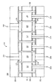
図1を見ると、一実施例における装置100が、マイクロ・エレクトロメカニカル・システム(MEMS)・ジャイロスコープを含む。ジャイロスコープは高精度航法角速度検知のために採用可能である。一実施例における装置100は、複数の振動梁102および104と、複数の駆動/センサ構成要素105、106、107、108、110、112、114、および116を含む。振動梁102および104の振動モードに応じて、第1サブグループの駆動/センサ構成要素105、106、107、108、110、112、114、および116は、振動梁102および104の第1振動を駆動し、第2サブグループの駆動/センサ構成要素105、106、107、108、110、112、114、および116は、振動梁102および104の第2のコリオリの力で誘導された振動を検知する。
Features of exemplary implementations of the invention will become apparent from the description, the claims, and the accompanying drawings.
Turning to FIG. 1, an
ある実施例では、振動梁102の駆動振動は第1方向(例えば面外方向)に沿っている。こうして、駆動/センサ構成要素105および106は振動梁102のための駆動構成要素として働き、駆動/センサ構成要素110および112は振動梁102のためのピックオフ・センサとして働く。別の実施例では、振動梁102の駆動振動は第2方向(例えば面内方向)に沿っている。こうして、駆動/センサ構成要素110および112は振動梁102のための駆動構成要素として働き、駆動/センサ構成要素105および106は振動梁102のためのピックオフ・センサとして働く。
In some embodiments, the drive vibration of the vibrating
ある実施例における複数の振動梁102および104は、各測定軸のために2つまたはそれ以上の振動梁を含む。例えば、振動梁102および104は両方とも1つの測定軸のための角速度の検知に寄与する。ある実施例における振動梁102および104は各々、長方形、三角形、または円形のプリズムを含む。例えば、長方形プリズムは、幅の寸法および高さの寸法より大きな長さの寸法を有する。別の実施例では、振動梁102は六角形または八角形の断面を有する。ある実施例における振動梁102および104は、高Qを達成するために低い内部損失を有する材料から作られている。例えば、高Q振動梁は振動を持続させるためにエネルギーをごく僅かしか必要としない。振動梁102および104の駆動方法および検知方法は、高Qを持続しながら振動梁102および104の運動を引き起こして読み出すために選択される。ある実施例では、振動梁102は一体シリコン・梁を含む。ある実施例では、振動梁102は、互いに接着された3つのシリコン層などの、複数のシリコン層を含む。例えば、3つのシリコン層は、中央層と、頂部カバー210(図2)と、底部カバー212(図2)とを含む。頂部カバー210と底部カバー212は、中央層を密封する働きをする。中央層は、振動梁102および104と駆動/センサ構成要素110、112、114、116とを含む。頂部カバー210は駆動/センサ構成要素105、106、107、108を含む。更に別の実施例では、振動梁102は、圧電駆動および検知を使用する一体水晶梁を含む。更に又別の実施例では、振動梁102は、磁気駆動および検知を使用する透過性材料を含む。
The plurality of vibrating
振動梁102は、垂直振動(例えば垂直方向の振動)のための1つまたは複数の節軸を含む。例えば、振動梁の102の垂直振動は節軸の周りに生じることができる。振動梁102は又、水平振動(例えば水平方向の振動)のための1つまたは複数の節軸を含む。例えば、振動梁の102の水平振動は節軸の周りに生じることができる。ある実施例における垂直振動のための節軸と水平振動のための節軸は、節点において交差している。節点は、複数の実質的に直角な方向の1つまたはそれ以上における振動のために、実質的に停止したままである。例えば節点は、垂直振動中と水平振動中の両方において実質的に停止したままである。振動梁102は1つまたは複数の連結構成要素120を含み、連結構成要素は、振動梁102の節点においてフレーム118を振動梁102に連結する働きをする。
The vibrating
ある実施例における振動梁102は、頂部カバー210と底部カバー212を通じてフレーム118に連結された屈曲構成要素122によって支持されている(図2)。屈曲構成要素122によって、振動梁102は角速度の発生によって節点の周りに移動できる。例えば、角速度は振動梁の縦軸の周りにある。ピックアップ・センサと処理構成要素は、振動梁102の移動を測定し、角速度の方向と大きさを表す信号に変換する。
The vibrating
屈曲構成要素122によって、節点の周りにおける振動梁102の水平振動と垂直振動が可能になる。屈曲構成要素122は、振動梁102の縦軸の中心線に沿っている振動梁の小さな区分を含む。ある実施例における節点は振動梁102の内部にある。例えば、振動梁102は、節点の周りの区域を露出する1つまたは複数の開口124を含む。ある実施例における開口124は、振動梁102を貫通している。開口124は節点と屈曲構成要素122とを取り囲み、振動梁102が移動するための空間を提供する。開口124は節点の近くにある。開口124によって、フレーム118は振動梁を実質的に節点の近くで支えることができる。開口124は、振動梁102の表面からエッチングされた開放空間を含み、節点を露出させ、屈曲構成要素122を形成する。
The
屈曲構成要素122は、振動梁102を取付け構成要素126に結合する。取付け構成要素126は、頂部カバー210と底部カバー212とを通じて振動梁102をフレーム118に結合する(図2)。節点の近くで振動梁102をフレーム118に結合することによって、振動梁102の最小限の並進振動エネルギーが、取付け構成要素126やフレーム118などの支持構成要素に伝達される。節点は実質的に停止したままであるから、振動梁102内部の節点近くにおける振動梁102と取付け構成要素126との連結は、支持構成要素に伝達される振動梁102の振動エネルギー量の低減を促進する。例えば、振動中に動いている振動梁102上のある位置において振動梁102をフレーム118に連結することは、振動エネルギーを振動梁102からフレーム118に伝達し、この結果感度が向上する。振動梁102を節点においてフレーム118に連結した場合には、振動梁102を振動中に動いている振動梁102上のある位置において連結した場合よりも、振動梁102において振動を持続するために必要なエネルギーは少なくなり、より高いQが達成される。
節点は、振動梁102の第1節点を含む。振動梁102は又、第2節点を含む。第2節点は第2屈曲構成要素(例えば、屈曲構成要素122に類似)および第2取付け構成要素(例えば取付け構成要素126に類似)に連結されている。ある実施例における屈曲構成要素は振動絶縁装置を含む。屈曲構成要素122は第1モーメントを取付け構成要素126に加える。第2屈曲構成要素は第2モーメントを第2取付け構成要素に加える。第2モーメントは第1モーメントと逆の極性を有する。こうして、第2モーメントは第1モーメントをフレーム118において相殺する。
The node includes the first node of the vibrating
ある実施例では、開口124は振動梁102を垂直方向に貫通している。別の実施例では、開口124は、振動梁102を垂直方向と水平方向の両方において対称的に貫通している。例えば、開口124は振動梁102を、振動梁102の頂部表面、並びに振動梁102の側部表面から貫通している。従って、弾性的特性は、振動梁102については垂直振動方向と水平振動方向の両方において実質的に類似している。開口124は振動梁102の頂部表面と側部表面とを貫通しているので、振動梁102の剛性は垂直振動方向と水平振動方向の両方において類似している。ある実施例における振動梁102は又、両振動方向において同じ共振振動数を有している。
In one embodiment, the
ある実施例における振動梁102および104は、振動梁102および104を支持するフレーム118の平面などの、一平面に実質的に存在する。ある実施例における振動梁102および104は、2つの直交方向において振動に関して対称である。例えば、振動梁102および104は、面内方向と面外方向の両方において振動に関して対称である。ある実施例では、振動梁102は、面外振動する振動梁104と同時に面内振動する。別の実施例では、振動梁102は、面内振動する振動梁104と同時に面外振動する。
The vibrating beams 102 and 104 in one embodiment are substantially in one plane, such as the plane of the
駆動/センサ構成要素105、106、107、108、110、112、114、および116の1つまたは複数が、所定の時間に駆動およびピックオフ構成要素として働き、振動梁102および104を制御された振幅の振動(例えば振動)にセットする。駆動/センサ構成要素105、106、107、108、110、112、114、および116の1つまたは複数は、所定の時間にセンサおよび強制構成要素として働き、第2振動をピックオフし、第2振動のゼロへの再均衡を強制し、振動梁102および104のその縦軸周りの角速度の大きさを測定する。ある実施例における駆動/センサ構成要素105、106、107、108、110、112、114、および116の各々は、所定の時間に駆動構成要素またはセンサ構成要素のいずれかとして働くこともできる。
One or more of the drive /
角速度検知ジャイロスコープを初期設定するために、駆動/センサ構成要素105、106、107、108、110、112、114、および116の駆動構成要素は、振動梁102および104の振動を起こさせる。振動梁102および104の、これらの縦軸周りの角速度と第1振動は、振動梁102および104の上にコリオリの力を誘導させる。コリオリの力は、振動梁102および104の第2振動を起こさせる。第2振動は第1振動に対して実質的に直角をなす。ある実施例におけるフィードバック構成要素は、第1振動を調整するために、第1振動の大きさに関するフィードバックを駆動構成要素106および108に提供する。駆動/センサ構成要素105、106、107、108、110、112、114、および116のセンサ構成要素は、第2振動をピックオフし、制御信号を適用してピックオフ信号をゼロにする。制御信号は、振動梁102および104の角速度の大きさと極性の尺度である。
In order to initialize the angular velocity sensing gyroscope, the drive components of the drive /
ある実施例における駆動/センサ構成要素105、106、107、108、110、112、114、および116の駆動構成要素は、静電駆動構成要素、磁気駆動、および/または圧電駆動構成要素を含むこともできる。ある実施例における駆動/センサ構成要素105、106、107、108、110、112、114、および116のセンサ構成要素は、容量性ピックオフ・センサ、磁気ピックオフ・センサ、および/または圧電ピックオフ・センサを含むこともできる。
The drive components of drive /
図1および2を参照すると、図1の線2−2に沿った角速度検知ジャイロスコープの断面図202が、駆動/センサ構成要素105、106、107、108、110、112、114、および116に結合された複数の接続構成要素204を示している。ある実施例における接続構成要素204は、駆動/センサ構成要素105、106、107、108、110、112、114、および116への電気経路を含む。ある実施例では、電気信号が接続構成要素204を通って移動し、駆動/センサ構成要素105、106、107、108、110、112、114、および116を制御する。ある実施例では、接続構成要素204は、面内運動を検知して制御信号を加えるための電気経路を含み、面内運動をゼロにサーボ制御する。例えば、電気信号が接続構成要素204を通って移動し、情報を駆動/センサ構成要素105、106、107、108、110、112、114、および116から、ジャイロスコープの角速度を決定するために電気信号を使用する処理構成要素に中継する。
With reference to FIGS. 1 and 2, a
装置100のある例示的な動作の例証的説明を、説明の目的で以下に行う。ある実施例における角速度検知ジャイロスコープは、角速度検知中に振動梁102および104の両方を使用する。振動梁102および104は複数の状態のいずれか1つの状態にあってもよい。例えば、ある時限中に、振動梁102および104のいずれかが振動活動状態にあって、角速度検知のために使用されてもよい。代りに、振動梁102および104のいずれかが、第1方向における振動から第2方向における振動への遷移状態にあってもよい。振動梁102および104の1つが遷移状態にある間は、ある実施例におけるジャイロスコープは、振動梁102および104の遷移状態のものから得られた角速度データを使用しない。振動梁102および104は、所定の頻度で活動状態と遷移状態との間を周期的に移動する。この頻度は、意図される適用例の1つまたは複数のパラメータに依存することもある。
An illustrative description of certain exemplary operations of
ある実施例における振動梁102および104は、実質的にフレーム118の平面の中にある。ジャイロスコープを始動するために、駆動/センサ構成要素105および106は駆動構成要素として働き、面外方向などの第1方向に振動梁102の振動を開始させる。いったん振動梁102が面外方向の動作振動に達すると(例えば、振動梁102が共振振動数と全振幅に達しすると)、センサ構成要素として働く駆動/センサ構成要素110および112は、コリオリの力によって誘導された振動梁102の振動を検知して、ゼロにサーボ制御して、第1時限中の振動梁102の角速度を決定する。駆動/センサ構成要素110および112は、コリオリの力によって誘導された面内方向の振動をピックオフして、制御電圧を加え、振動をゼロにサーボ制御する。第1時限中に、駆動/センサ構成要素107および108は駆動構成要素として働き、面外方向または面内方向などの第1または第2方向の1つに振動梁104の振動を開始させる。例えば、駆動/センサ構成要素107および108は、面外方向に振動梁104の振動を開始させる。
The vibrating beams 102 and 104 in one embodiment are substantially in the plane of the
駆動/センサ構成要素105および106が面外方向に振動梁102を振動させる時限中に、ある実施例における駆動/センサ構成要素110および112は、コリオリの力によって誘導された面内方向の振動梁102の振動を検知し、ゼロにサーボ制御する。駆動/センサ構成要素110および112が面内方向に振動梁102を振動させる時限中に、ある実施例における駆動/センサ構成要素105および106は、コリオリの力によって誘導された面外方向の振動梁102の振動を検知し、ゼロにサーボ制御する。
During the time period during which drive /
第1時限が終了すると、振動梁104は遷移状態から活動状態へ移動し、第2時限の持続中に、振動梁102は活動状態から遷移状態へ移動する。第2時限中に、振動梁104は面外方向に振動し、駆動/センサ構成要素114および116は、コリオリの力によって誘導された振動梁104の振動を検知して、ゼロにサーボ制御して、振動梁104の角速度を決定する。駆動/センサ構成要素114および116は、コリオリの力によって誘導された面内方向の振動をピックオフして、制御電圧を加え、面内方向振動をゼロにサーボ制御する。遷移状態では、駆動/センサ構成要素110および112は駆動構成要素として働き、振動梁102の振動を面外方向から面内方向などの第2方向に変える。振動梁102の第1振動方向は実質的に第2振動方向に直角をなしている。
When the first time period ends, the vibrating
第2時限が終了すると、振動梁102は遷移状態から活動状態へ移動し、第3時限の持続中に、振動梁104は活動状態から遷移状態へ移動する。第3時限中に、振動梁102は面内方向に振動し、駆動/センサ構成要素105および106は、コリオリの力によって誘導された振動梁102の振動を検知して、ゼロにサーボ制御して、振動梁102の角速度を決定する。駆動/センサ構成要素105および106は、コリオリの力によって誘導された面外方向の振動をピックオフして、制御信号を加え、振動をゼロにサーボ制御する。遷移状態では、駆動/センサ構成要素114および116は駆動構成要素として働き、振動梁104の振動を面外方向から面内方向に変える。
When the second time period ends, the vibrating
第3時限が終了すると、振動梁104は遷移状態から活動状態へ移動し、第4時限の持続中に、振動梁102は活動状態から遷移状態へ移動する。第4時限中に、振動梁104は面内方向に振動し、駆動/センサ構成要素107および108は、コリオリの力によって誘導された振動梁104の振動を検知して、ゼロにサーボ制御して、振動梁104の角速度を決定する。駆動/センサ構成要素107および108は、コリオリの力によって誘導された面外方向の振動をピックオフして、制御信号を加え、振動をゼロにサーボ制御する。遷移状態では、駆動/センサ構成要素105および106は駆動構成要素として働き、振動梁102の振動を面内方向から面外方向に変える。
When the third time period ends, the vibrating
第4時限が終了すると、振動梁102は遷移状態から活動状態へ移動し、第5時限の持続中に、振動梁104は活動状態から遷移状態へ移動する。従って、第4時限の後に、振動梁102および104は第1時限の初期状態に戻り、動作持続時間に関して上に述べた遷移および活動状態を経て進行することができる。
When the fourth time period ends, the vibrating
振動梁102および104の駆動モードおよび検知モードを周期的に逆転することによって、ジャイロスコープの時間と温度によるバイアス不確実性は減少する。振動梁102が単に面外または面内方向に駆動される場合には、バイアス誤差は時間と温度と共に変化する。面内方向に関する正のバイアス誤差の一因となる誤差期限には、面外方向に関する負のバイアス誤差の一因になるものもある。従って、面外バイアス誤差と面内バイアス誤差は、振動梁102および104の駆動モードと検知モードとを周期的に変えることにより、平均によってゼロに近い値に達する。
By periodically reversing the driving and sensing modes of the vibrating
装置100の別の例示的な動作の例証的説明を、説明の目的で以下に行う。ある実施例において、ジャイロスコープの動作時間は比較的長いことがある。こうして、ジャイロスコープの動作中に、駆動/センサ構成要素105、106、107、108、110、112、114、および116は、上述の様に周期的に駆動機能とピックオフ機能との間で動作モードを変える。別の実施例では、ジャイロスコープの動作時間は比較的短く、全動作時間中の振動梁102および104の遷移振動方向には望ましくない。その代わり、ジャイロスコープの始動によって、駆動/センサ構成要素105、106、107、108、110、112、114、および116は、較正時限中に振動梁102および104の振動方向を周期的に変えてもよい。較正時限は、振動梁102および104の動作のバイアス誤差を推定する。こうして、ジャイロスコープは動作中に推定バイアス誤差を調節することができ、振動梁102および104は動作中に活動振動状態にあることができる。
An illustrative description of another exemplary operation of
ある実施例における装置100は、ハードウェア構成要素などの複数の構成要素を含む。装置100の一実施例の中で、多くのこの様な構成要素を組み合わせるかまたは分割することができる。ある実施例における装置100は、どの(例えば水平、斜め、垂直)方向配置も含み、本明細書における説明および図は、説明を目的とする装置100の一例示的方向配置を示している。
The
本明細書に説明した工程または動作は単なる例示的なものである。これらの工程または動作には、本発明の精神から逸脱することなく多くの変形があり得る。例えば、各工程を異なる順序で実施してもよく、または工程を追加、削除、または変更してもよい。 The steps or operations described herein are just exemplary. There may be many variations to these steps or operations without departing from the spirit of the invention. For example, the steps may be performed in a different order, or steps may be added, deleted, or changed.
本発明の例示的な実行を本明細書に図示し詳細に説明したが、本発明の精神から逸脱することなく、様々な変更、追加、代用などを行うことができ、従ってこれらは冒頭の特許請求の範囲に定義された本発明の範囲内にあると考えられることは、当業者には明らかになろう。 While exemplary implementations of the invention have been illustrated and described in detail herein, various changes, additions, substitutions, and the like can be made without departing from the spirit of the invention, and these are therefore subject to the opening patents. It will be apparent to those skilled in the art that they are considered to be within the scope of the invention as defined in the claims.
Claims (16)
第1振動梁と、
前記第1振動梁と平行であって面を規定する第2振動梁と、
前記第1振動梁が、前記第1および第2振動梁によって規定される前記面に垂直である第1方向または該面に平行である第2方向に振動できるように、前記第1振動梁の周囲に配置された第1組の駆動/センサ構成要素と、
前記第2振動梁が、前記第1方向または前記第2方向に振動できるように、前記第2振動梁の周囲に配置された第2組の駆動/センサ構成要素とを含み、
第1時限中に、前記第1組の駆動/センサ構成要素は、前記装置の角速度または回転を検知するために、前記第1振動梁を前記第1方向に振動させ、一方、前記第2組の駆動/センサ構成要素は、前記第2振動梁を前記第2方向の振動から前記第1方向の振動へと遷移させ、
前記第1時限の直後の第2時限中に、前記第2組の駆動/センサ構成要素は、前記装置の角速度または回転を検知するために、前記第2振動梁を前記第1方向に振動させ、一方、前記第1組の駆動/センサ構成要素は、前記第1振動梁を前記第1方向の振動から前記第2方向の振動へと遷移させる、装置。
A device for measuring angular velocity and rotation,
A first vibrating beam;
A second vibrating beam parallel to the first vibrating beam and defining a surface;
The first vibrating beam can be vibrated in a first direction perpendicular to the plane defined by the first and second vibrating beams or in a second direction parallel to the plane. A first set of drive / sensor components disposed around;
A second set of drive / sensor components disposed around the second vibrating beam such that the second vibrating beam can vibrate in the first direction or the second direction;
During a first time period, the first set of drive / sensor components vibrates the first vibrating beam in the first direction to detect angular velocity or rotation of the device, while the second set The drive / sensor component of the second device causes the second vibrating beam to transition from the vibration in the second direction to the vibration in the first direction,
During a second time period immediately after the first time period, the second set of drive / sensor components causes the second vibrating beam to vibrate in the first direction to detect angular velocity or rotation of the device. Meanwhile, the first set of drive / sensor components transitions the first vibrating beam from vibration in the first direction to vibration in the second direction.
The apparatus of claim 1, wherein the first and second vibrating beams comprise rectangular, triangular, hexagonal, octagonal, or circular columns.
The apparatus of claim 1, wherein the first direction is substantially perpendicular to the second direction.
The apparatus of claim 3, further comprising a frame that supports the first and second vibrating beams in the plane.
The first and second sets of drive / sensor components change the first and second vibrating beams in a vibrating activity state that detects an angular velocity of the device and a vibration direction of the first and second vibrating beams. The apparatus according to claim 1, wherein the apparatus is periodically switched between transition states.
前記第1及び第2振動梁の1つは所定の時間に前記振動活動状態にあり、
前記処理構成要素は、前記振動活動状態において、前記第1及び第2振動梁の1つからのコリオリの力によって誘導される振動の情報を使用して、前記所定の時間に前記装置の角速度の方向と大きさを測定する、請求項5に記載の装置。
Further including a processing component;
One of the first and second vibrating beams is in the vibration active state at a predetermined time;
The processing component uses information of vibration induced by Coriolis force from one of the first and second vibrating beams in the vibration active state to determine the angular velocity of the device at the predetermined time. 6. The apparatus of claim 5, wherein the apparatus measures direction and magnitude.
The apparatus of claim 1, wherein the first and second sets of drive / sensor components periodically switch vibration directions of the first and second vibrating beams to reduce angular velocity measurement errors.
前記第1および第2方向における前記第1および第2振動梁の振動を交互に行うことで、複数の時限にわたって相殺する反対極性の角速度測定バイアス誤差を生成する、請求項7に記載の装置。
A frame that supports the first and second vibrating beams in the plane;
8. The apparatus of claim 7, wherein alternating vibrations of the first and second vibrating beams in the first and second directions generate an opposite polarity angular velocity measurement bias error that cancels over a plurality of time periods.
The apparatus of claim 1, wherein the first and second sets of drive / sensor components comprise electrostatic drive / sensor components, magnetic drive / sensor components, or piezoelectric drive / sensor components.
前記第1及び第2時限は較正動作の一部であり、
前記第1組及び第2組の駆動/センサ構成要素は、前記装置の推定バイアス誤差を発生するために、前記較正動作の間に、前記第1および第2振動梁の前記第1方向への振動と前記第1および第2振動梁の前記第2方向への振動とを周期的に遷移させ、
前記較正動作の後、前記装置の動作中、前記処理構成要素が、前記装置の角速度の方向および大きさ、または前記装置の回転を測定するために、前記推定バイアス誤差を調節する、請求項1に記載の装置。
Further comprising a processing component for controlling the first set and the second set of drive / sensor components;
The first and second time periods are part of the calibration operation;
The first set and second set of drive / sensor components are adapted to move the first and second vibrating beams in the first direction during the calibration operation to generate an estimated bias error of the device. Periodically transitioning vibrations and vibrations of the first and second vibrating beams in the second direction;
2. After the calibration operation, during operation of the device, the processing component adjusts the estimated bias error to measure the direction and magnitude of the angular velocity of the device, or rotation of the device. The device described in 1.
前記第1および第2振動梁は、複数の屈曲構成部分を前記複数の節点の周りに露出させる複数の開口を含み、
前記装置は、前記複数の屈曲構成部分に結合して、該第1および第2振動梁を該複数の節点において支持するフレームをさらに含む、請求項1に記載の装置。
The first and second vibrating beams include a plurality of nodes for vibration in both the first direction and the second direction, the plurality of nodes being within the first and second vibrating beams;
The first and second vibrating beams include a plurality of openings that expose a plurality of bent components around the plurality of nodes;
The apparatus of claim 1, further comprising a frame coupled to the plurality of bending components to support the first and second vibrating beams at the plurality of nodes.
前記第1組および第2組の駆動/センサ構成要素は、前記第1および第2振動梁が振動の方向を変える遷移状態にある期間の第2モードで、前記第1および第2振動梁を動作させる、請求項1に記載の装置。
The first and second sets of drive / sensor components are arranged in the first and second directions in which the first and second vibrating beams are induced by Coriolis forces for measurement of the angular velocity of the device. Operating the first and second vibrating beams in a first mode, which is a period for detecting vibrations of the first and second vibrating beams in
The first set and the second set of drive / sensor components are configured to move the first and second vibrating beams in a second mode during a period in which the first and second vibrating beams are in a transition state that changes the direction of vibration. The apparatus according to claim 1, wherein the apparatus is operated.
前記第1及び第2振動梁の各々は、前記複数の節点の周りに複数の開口を含み、該複数の節点は、該第1及び第2振動梁の複数の節点においてフレームが第1及び第2振動梁を支持することを可能にする、請求項1に記載の装置。
Each of the first and second vibrating beams includes a plurality of nodes for vibration in both the first direction and the second direction;
Each of the first and second vibrating beams includes a plurality of openings around the plurality of nodes, and the plurality of nodes have first and second frames at the plurality of nodes of the first and second vibrating beams. The device according to claim 1, which makes it possible to support two vibrating beams.
第1時限中に、前記ジャイロスコープの角速度または回転を検知するために、該ジャイロスコープの第1振動梁を前記面に垂直な第1方向に振動させる工程と、
前記第1時限直後である第2時限中に、前記第1振動梁の振動を、前記第1方向から該第1方向に平行な第2方向へと変化させる工程と、
前記第2時限中に、前記ジャイロスコープの角速度または回転を検知するために、該ジャイロスコープの第2振動梁を前記面に垂直な前記第1方向に振動させる工程と、
前記第2時限直後である第3時限中に、前記第2振動梁の振動を前記第1方向から前記第2方向へと変化させる工程と、
前記第3時限中に、前記ジャイロスコープの角速度または回転を検知するために、前記第1振動梁を前記第2方向に振動させる工程とを含む方法。
A method of operating a vibrating beam gyroscope having a first vibrating beam and a second vibrating beam that are parallel to each other and that define a plane,
Oscillating a first vibrating beam of the gyroscope in a first direction perpendicular to the surface to detect angular velocity or rotation of the gyroscope during a first time period;
Changing the vibration of the first vibrating beam from the first direction to a second direction parallel to the first direction during a second time period immediately after the first time period;
Oscillating a second vibrating beam of the gyroscope in the first direction perpendicular to the plane to detect angular velocity or rotation of the gyroscope during the second time period;
Changing the vibration of the second vibrating beam from the first direction to the second direction during a third time period immediately after the second time period;
Oscillating the first vibrating beam in the second direction to detect angular velocity or rotation of the gyroscope during the third time period.
前記第1時限中に、前記ジャイロスコープの角速度または回転を検知するために、該ジャイロスコープの第1振動梁を前記面に垂直な第1方向に振動させる工程は、
前記第1振動梁の第1方向の振動を駆動する工程と、
前記ジャイロスコープの角速度を決定するために、コリオリの力によって誘導される前記第2方向における該第1振動梁の振動を検知する工程と、
を含み、
前記第2時限中に、前記ジャイロスコープの角速度または回転を検知するために、該ジャイロスコープの第2振動梁を前記面に垂直な前記第1方向に振動させる工程は、
前記第2振動梁の前記第1方向の振動を駆動する工程と、
前記ジャイロスコープの角速度を決定するために、コリオリの力によって誘導される前記第2方向における前記第2振動梁の振動を検知する工程と
を含み、
前記第3時限中に、前記ジャイロスコープの角速度または回転を検知するために、前記第1振動梁を前記第2方向に振動させる工程は、
前記第1振動梁の第2方向の振動を駆動する工程と、
前記ジャイロスコープの角速度を決定するために、コリオリの力によって誘導される第1方向における第1振動梁の振動を検知する工程と
を含む、請求項14に記載の方法。
The first and second vibrating beams include rectangular prisms, and the first direction is substantially perpendicular to the second direction;
During the first time period, in order to detect an angular velocity or rotation of the gyroscope, the step of vibrating the first vibrating beam of the gyroscope in a first direction perpendicular to the plane includes:
Driving the vibration in the first direction of the first vibrating beam;
Detecting vibration of the first vibrating beam in the second direction induced by Coriolis force to determine an angular velocity of the gyroscope;
Including
Oscillating the second vibrating beam of the gyroscope in the first direction perpendicular to the surface to detect angular velocity or rotation of the gyroscope during the second time period,
Driving the vibration in the first direction of the second vibrating beam;
Detecting vibration of the second vibrating beam in the second direction induced by Coriolis force to determine an angular velocity of the gyroscope;
During the third time period, in order to detect an angular velocity or rotation of the gyroscope, the step of vibrating the first vibrating beam in the second direction includes:
Driving the vibration in the second direction of the first vibrating beam;
Wherein in order to determine the gyroscope angular, and a step of detecting vibration of the first vibrating beam in the first direction induced by the Coriolis force, the method according to claim 14.
Applications Claiming Priority (2)
| Application Number | Priority Date | Filing Date | Title |
|---|---|---|---|
| US54970904P | 2004-03-03 | 2004-03-03 | |
| US60/549709 | 2004-03-03 |
Publications (2)
| Publication Number | Publication Date |
|---|---|
| JP2005249792A JP2005249792A (en) | 2005-09-15 |
| JP4995427B2 true JP4995427B2 (en) | 2012-08-08 |
Family
ID=34749079
Family Applications (1)
| Application Number | Title | Priority Date | Filing Date |
|---|---|---|---|
| JP2005058460A Expired - Fee Related JP4995427B2 (en) | 2004-03-03 | 2005-03-03 | Electromechanical system including an oscillating beam |
Country Status (4)
| Country | Link |
|---|---|
| EP (1) | EP1571417B1 (en) |
| JP (1) | JP4995427B2 (en) |
| CA (1) | CA2498115A1 (en) |
| DE (1) | DE602005023367D1 (en) |
Families Citing this family (9)
| Publication number | Priority date | Publication date | Assignee | Title |
|---|---|---|---|---|
| CA2498178A1 (en) * | 2004-03-03 | 2005-09-03 | Northrop Grumman Corporation | Support of vibrating beam near nodal point |
| US7886598B2 (en) * | 2005-08-08 | 2011-02-15 | Northrop Grumman Guidance And Electronics Company, Inc. | Vibratory gyro bias error cancellation using mode reversal |
| US7565839B2 (en) | 2005-08-08 | 2009-07-28 | Northrop Grumman Guidance And Electronics Company, Inc. | Bias and quadrature reduction in class II coriolis vibratory gyros |
| US7739896B2 (en) * | 2007-03-15 | 2010-06-22 | Northrop Grumman Guidance And Electronics Company, Inc. | Self-calibration of scale factor for dual resonator class II coriolis vibratory gyros |
| FR2925669B1 (en) * | 2007-12-21 | 2010-01-15 | Sagem Defense Securite | MEASUREMENT BY GYROSCOPIC SYSTEM |
| FR2937414B1 (en) | 2008-10-20 | 2010-11-26 | Sagem Defense Securite | GYROSCOPIC MEASUREMENT BY A VIBRANT GYROSCOPE |
| FR2939193B1 (en) * | 2008-11-28 | 2011-03-04 | Sagem Defense Securite | CALIBRATION OF VIBRANT GYROSCOPE |
| FR2959010B1 (en) * | 2010-04-16 | 2013-01-18 | Sagem Defense Securite | GYROSCOPIC MEASUREMENT IN A NAVIGATION SYSTEM |
| FR2959009B1 (en) * | 2010-04-16 | 2012-06-29 | Sagem Defense Securite | GYROSCOPIC MEASUREMENT BY A VIBRANT GYROSCOPE IN PRECESSION |
Family Cites Families (8)
| Publication number | Priority date | Publication date | Assignee | Title |
|---|---|---|---|---|
| JPH082567Y2 (en) * | 1987-07-17 | 1996-01-29 | 日本電気ホームエレクトロニクス株式会社 | Vibrating gyro |
| JPS6415114U (en) * | 1987-07-17 | 1989-01-25 | ||
| US5056366A (en) * | 1989-12-26 | 1991-10-15 | Litton Systems, Inc. | Piezoelectric vibratory rate sensor |
| JPH06123630A (en) * | 1992-10-13 | 1994-05-06 | Sumitomo Electric Ind Ltd | Vibration gyroscopic device and detection of angular velocity |
| US5708320A (en) * | 1994-10-28 | 1998-01-13 | Alps Electric Co., Ltd | Vibratory gyroscope |
| JP3656544B2 (en) * | 2000-11-10 | 2005-06-08 | 株式会社村田製作所 | Composite vibrator, vibratory gyroscope using the same, and method of manufacturing composite vibrator |
| JP4068370B2 (en) * | 2001-09-07 | 2008-03-26 | シチズンホールディングス株式会社 | Vibrating gyro |
| CA2498178A1 (en) * | 2004-03-03 | 2005-09-03 | Northrop Grumman Corporation | Support of vibrating beam near nodal point |
-
2005
- 2005-02-23 CA CA 2498115 patent/CA2498115A1/en not_active Abandoned
- 2005-02-28 DE DE200560023367 patent/DE602005023367D1/en active Active
- 2005-02-28 EP EP20050251194 patent/EP1571417B1/en not_active Expired - Fee Related
- 2005-03-03 JP JP2005058460A patent/JP4995427B2/en not_active Expired - Fee Related
Also Published As
| Publication number | Publication date |
|---|---|
| EP1571417B1 (en) | 2010-09-08 |
| JP2005249792A (en) | 2005-09-15 |
| CA2498115A1 (en) | 2005-09-03 |
| EP1571417A2 (en) | 2005-09-07 |
| EP1571417A3 (en) | 2006-12-20 |
| DE602005023367D1 (en) | 2010-10-21 |
Similar Documents
| Publication | Publication Date | Title |
|---|---|---|
| JP4995427B2 (en) | Electromechanical system including an oscillating beam | |
| JP5161440B2 (en) | Vibrating beam gyroscope, driving method of vibrating beam gyroscope | |
| US8534127B2 (en) | Extension-mode angular velocity sensor | |
| US9395183B2 (en) | Micromachined gyroscope including a guided mass system | |
| JP5161441B2 (en) | Vibrating gyroscope | |
| US7174785B2 (en) | Oscillation of vibrating beam in a first direction for a first time period and a second direction for a second time period to sense angular rate of the vibrating beam | |
| JP2000346649A (en) | Micro gyroscope | |
| JP2004527387A (en) | Suspended micro-machined structure | |
| US20230266125A1 (en) | Mems gyroscope for three-axis detection | |
| US8561466B2 (en) | Vibratory gyro bias error cancellation using mode reversal | |
| JP2001255153A (en) | Separated multi-disk gyroscope | |
| Shah et al. | Modal analysis of a single-structure multiaxis MEMS gyroscope | |
| CN113959423A (en) | MEMS gyroscope and electronic equipment | |
| CN115615416A (en) | Fully-decoupled three-axis MEMS gyroscope | |
| JP4995426B2 (en) | Electromechanical system including vibrating beams | |
| JP2007047167A (en) | Nodal position correction method of vibrating beam | |
| US20230408256A1 (en) | Mems gyroscope sensing in-plane rotations | |
| US7322238B2 (en) | Support of vibrating beam near nodal point | |
| Shah et al. | Research Article Modal Analysis of a Single-Structure Multiaxis MEMS Gyroscope | |
| JPH0587574A (en) | Vibration gyroscope |
Legal Events
| Date | Code | Title | Description |
|---|---|---|---|
| A621 | Written request for application examination |
Free format text: JAPANESE INTERMEDIATE CODE: A621 Effective date: 20080225 |
|
| A977 | Report on retrieval |
Free format text: JAPANESE INTERMEDIATE CODE: A971007 Effective date: 20110126 |
|
| A131 | Notification of reasons for refusal |
Free format text: JAPANESE INTERMEDIATE CODE: A131 Effective date: 20110202 |
|
| A521 | Written amendment |
Free format text: JAPANESE INTERMEDIATE CODE: A523 Effective date: 20110331 |
|
| A711 | Notification of change in applicant |
Free format text: JAPANESE INTERMEDIATE CODE: A711 Effective date: 20110912 |
|
| A131 | Notification of reasons for refusal |
Free format text: JAPANESE INTERMEDIATE CODE: A131 Effective date: 20111221 |
|
| RD03 | Notification of appointment of power of attorney |
Free format text: JAPANESE INTERMEDIATE CODE: A7423 Effective date: 20111227 |
|
| A521 | Written amendment |
Free format text: JAPANESE INTERMEDIATE CODE: A523 Effective date: 20120106 |
|
| RD04 | Notification of resignation of power of attorney |
Free format text: JAPANESE INTERMEDIATE CODE: A7424 Effective date: 20120125 |
|
| TRDD | Decision of grant or rejection written | ||
| A01 | Written decision to grant a patent or to grant a registration (utility model) |
Free format text: JAPANESE INTERMEDIATE CODE: A01 Effective date: 20120411 |
|
| A01 | Written decision to grant a patent or to grant a registration (utility model) |
Free format text: JAPANESE INTERMEDIATE CODE: A01 |
|
| A61 | First payment of annual fees (during grant procedure) |
Free format text: JAPANESE INTERMEDIATE CODE: A61 Effective date: 20120510 |
|
| FPAY | Renewal fee payment (event date is renewal date of database) |
Free format text: PAYMENT UNTIL: 20150518 Year of fee payment: 3 |
|
| R150 | Certificate of patent or registration of utility model |
Free format text: JAPANESE INTERMEDIATE CODE: R150 |
|
| R250 | Receipt of annual fees |
Free format text: JAPANESE INTERMEDIATE CODE: R250 |
|
| R250 | Receipt of annual fees |
Free format text: JAPANESE INTERMEDIATE CODE: R250 |
|
| LAPS | Cancellation because of no payment of annual fees |