JP4995244B2 - Ophthalmic imaging equipment - Google Patents
Ophthalmic imaging equipment Download PDFInfo
- Publication number
- JP4995244B2 JP4995244B2 JP2009196997A JP2009196997A JP4995244B2 JP 4995244 B2 JP4995244 B2 JP 4995244B2 JP 2009196997 A JP2009196997 A JP 2009196997A JP 2009196997 A JP2009196997 A JP 2009196997A JP 4995244 B2 JP4995244 B2 JP 4995244B2
- Authority
- JP
- Japan
- Prior art keywords
- light
- eye
- examined
- optical system
- camera
- Prior art date
- Legal status (The legal status is an assumption and is not a legal conclusion. Google has not performed a legal analysis and makes no representation as to the accuracy of the status listed.)
- Expired - Fee Related
Links
- 238000003384 imaging method Methods 0.000 title claims description 33
- 230000003287 optical effect Effects 0.000 claims description 65
- 230000002911 mydriatic effect Effects 0.000 claims description 55
- 238000005286 illumination Methods 0.000 claims description 25
- 230000004044 response Effects 0.000 claims description 5
- 238000000034 method Methods 0.000 description 21
- 230000008569 process Effects 0.000 description 19
- 238000010586 diagram Methods 0.000 description 6
- 230000002207 retinal effect Effects 0.000 description 6
- 210000004220 fundus oculi Anatomy 0.000 description 4
- 238000002360 preparation method Methods 0.000 description 3
- 230000011514 reflex Effects 0.000 description 3
- 208000006550 Mydriasis Diseases 0.000 description 2
- 230000004397 blinking Effects 0.000 description 2
- 210000004087 cornea Anatomy 0.000 description 2
- 230000000694 effects Effects 0.000 description 2
- 210000001747 pupil Anatomy 0.000 description 2
- 230000008901 benefit Effects 0.000 description 1
- 230000005540 biological transmission Effects 0.000 description 1
- 230000008859 change Effects 0.000 description 1
- 230000004907 flux Effects 0.000 description 1
- 229910052736 halogen Inorganic materials 0.000 description 1
- 125000005843 halogen group Chemical group 0.000 description 1
- 239000002637 mydriatic agent Substances 0.000 description 1
- 230000009467 reduction Effects 0.000 description 1
- 238000002310 reflectometry Methods 0.000 description 1
- 238000004904 shortening Methods 0.000 description 1
Images


Classifications
-
- A—HUMAN NECESSITIES
- A61—MEDICAL OR VETERINARY SCIENCE; HYGIENE
- A61B—DIAGNOSIS; SURGERY; IDENTIFICATION
- A61B3/00—Apparatus for testing the eyes; Instruments for examining the eyes
- A61B3/10—Objective types, i.e. instruments for examining the eyes independent of the patients' perceptions or reactions
- A61B3/12—Objective types, i.e. instruments for examining the eyes independent of the patients' perceptions or reactions for looking at the eye fundus, e.g. ophthalmoscopes
-
- A—HUMAN NECESSITIES
- A61—MEDICAL OR VETERINARY SCIENCE; HYGIENE
- A61B—DIAGNOSIS; SURGERY; IDENTIFICATION
- A61B3/00—Apparatus for testing the eyes; Instruments for examining the eyes
- A61B3/10—Objective types, i.e. instruments for examining the eyes independent of the patients' perceptions or reactions
- A61B3/14—Arrangements specially adapted for eye photography
- A61B3/145—Arrangements specially adapted for eye photography by video means
Description
本発明は、例えば眼科医院や集団健診等で用いられ、被検眼を観察しながら画像記録を行う眼科撮影装置に関するものである。 The present invention relates to an ophthalmologic photographing apparatus that is used in, for example, an ophthalmic clinic or a group medical examination and records an image while observing an eye to be examined.
眼科撮影装置として、被検眼の眼底撮影を行う眼底カメラが広く知られている。眼底カメラには、観察時に被検眼が眩しさを感じない近赤外光を用い、静止画を撮影する瞬間に、可視光で眼底を照明して眼底撮影を行う無散瞳型眼底カメラがよく用いられている。 As an ophthalmologic photographing apparatus, a fundus camera for photographing the fundus of a subject's eye is widely known. A non-mydriatic type fundus camera that uses near-infrared light that does not feel dazzling during observation and illuminates the fundus with visible light and shoots the fundus at the moment of taking a still image. It is used.
この無散瞳型眼底カメラでは、眼底カメラ内に観察と撮影が可能なセンサを内蔵することで、装置の小型化を実現している。更に、撮影スイッチの操作からの画像取得までの時間を短縮しながら、反射率が異なる被検眼に対する頻繁な観察光量の煩わしい操作の改善を行った眼底カメラが、特許文献1に開示されている。
In this non-mydriatic retinal camera, a sensor capable of observation and photographing is built in the retinal camera, thereby realizing a reduction in size of the apparatus. Further,
また、被検眼に散瞳剤を点眼し、観察・撮影時に共に可視光を用いて精密な眼底検査及び眼底撮影を行う散瞳型眼底カメラもよく用いられている。 In addition, a mydriatic retinal camera is often used that applies a mydriatic agent to the eye to be examined and performs precise fundus examination and fundus imaging using visible light during both observation and imaging.
この散瞳型眼底カメラと、先の無散瞳型眼底カメラとを一体化させることで、多機能化を実現している散瞳・無散瞳一体型眼底カメラが知られている。更に、散瞳・無散瞳の機能の切換手段により、散瞳時は可視観察、無散瞳時は赤外観察に切換える眼底カメラが特許文献2に開示されている。
A mydriatic / non-mydriatic retinal camera that realizes multiple functions by integrating this mydriatic retinal camera and the previous non-mydriatic retinal camera is known. Further,
そして、近年ではデジタル化が容易なことから、眼底カメラの撮影用カメラに、一般に使われるデジタルカメラが多く用いられるようになってきている。特に、一眼レフタイプのデジタルカメラが用いられるのは、眼底カメラからのリモート撮影が可能であることに加え、今までのフィルムタイプのカメラとの互換性が良く、解像度も眼科用の診断画像として十分なためである。更に、一般に使われるデジタルカメラであるので、高解像度化する最新機能のセンサが内蔵されることが多い。 In recent years, since digitalization is easy, generally used digital cameras are increasingly used as photographing cameras for fundus cameras. In particular, single-lens reflex digital cameras are used because they can be taken remotely from the fundus camera, are compatible with conventional film-type cameras, and have a resolution of ophthalmic diagnostic images. This is enough. Furthermore, since it is a digital camera that is generally used, it is often built-in a sensor having the latest function for increasing the resolution.
最近では、この一眼レフタイプのデジタルカメラのセンサを静止画記録だけではなく、動画観察や動画記録の用途に用いるライブビュー機能が追加されている。一般的に、ライブビュー機能はファインダを覗かなくとも撮影できるので、撮影アングルの自由度が大きくなるという利点がある。近年の眼底カメラでは、アライメントやピント合わせを行う観察用時に、このライブビュー機能を用いたものも提案されている。 Recently, a live view function has been added in which the sensor of this single-lens reflex digital camera is used not only for still image recording but also for moving image observation and moving image recording. Generally, the live view function can take an image without looking through the viewfinder, and thus has an advantage that the degree of freedom of the shooting angle is increased. In recent years, fundus cameras have been proposed that use this live view function for observation for alignment and focusing.
しかしながら特許文献1では、眼底カメラ内に観察と撮影が可能なセンサを内蔵することになるため、一般に使われるデジタルカメラは使用されていない。
However, in
また、特許文献2の眼底カメラでは、無散瞳時の観察を行うためのCCD及びその観察光学系が構成されており、観察用の撮像素子と撮影用の撮像素子を構成する必要がある。これらの課題を解決するために、近年では無散瞳時の観察を行うためのCCD及びその観察光学系を、一般に使われるデジタルカメラとライブビュー機能を用いることで、解決する方法が考えられている。
In addition, the fundus camera of
ところが無散瞳眼底カメラでは、観察時に被検眼に眩しさを感じさせない近赤外光を用い、静止画を撮影する瞬間に可視光で眼底を照明して眼底撮影を行うように構成されている。このため、撮影時の可視光照明のタイミング信号が必要になり、そのタイミング信号は一般に使われるデジタルカメラのシャッタ幕のX接点信号である開放信号を用いている。そして、ライブビュー機能の使用中は、シャッタ幕が開放状態になっているため、上記のタイミング信号を必要とする場合には、撮影の瞬間にシャッタ幕を開放状態から一旦は閉じた状態に戻さなければならない。 However, the non-mydriatic fundus camera is configured to shoot the fundus by illuminating the fundus with visible light at the moment of taking a still image, using near-infrared light that does not make the subject's eye feel dazzling during observation. . For this reason, a timing signal of visible light illumination at the time of photographing is required, and the timing signal uses an open signal that is an X contact signal of a shutter curtain of a commonly used digital camera. When the live view function is in use, the shutter curtain is in the open state. If the timing signal is required, the shutter curtain is returned from the open state to the closed state at the moment of shooting. There must be.
従って、一般に使われるデジタルカメラのライブビュー機能を用いて、被検眼の観察と撮影を行う場合に、検者が撮影開始操作をしてから実際に撮影が実行されるまでに時間を要することになる。そのため、撮影の瞬間に被検眼の固視位置が動いたり瞬きが発生することで、撮影の失敗を招く可能性がある。 Therefore, when observing and photographing the eye to be inspected using the live view function of a commonly used digital camera, it takes time from the start of the photographing start operation to the actual photographing by the examiner. Become. For this reason, the fixation position of the eye to be inspected or blinking at the moment of photographing may cause photographing failure.
本発明の目的は、上述の問題点を解消し、ライブビュー機能を備えた無散瞳型又は散瞳・無散瞳一体型の眼科撮影装置を提供することにある。 An object of the present invention is to provide a non-mydriatic type or a mydriatic / non-mydriatic ophthalmologic photographing apparatus that solves the above-described problems and has a live view function.
上記目的を達成するための本発明に係る眼科撮影装置は、
被検眼を照明する照明光学系と、前記照明光学系により赤外光と可視光とのいずれか一方で照明した前記被検眼を撮影する撮影光学系とを備える眼底カメラ本体と、前記撮影光学系を介して前記被検眼からの戻り光を受光する受光面を有する撮像手段を備え且つ前記眼底カメラ本体に着脱可能であるカメラとから構成される眼科撮影装置であって、
前記照明光学系を介して被検眼に照明する赤外光を発生させるための第1の光源を消灯した後に、前記撮像手段で受光した光に基づく電荷をリフレッシュし、前記照明光学系を介して前記被検眼に照明する可視光を発生させるための第2の光源を発光させる制御手段と、
を有することを特徴とする。
To achieve the above object, an ophthalmologic photographing apparatus according to the present invention provides:
A fundus camera body comprising: an illumination optical system that illuminates the eye to be examined; and a photographing optical system that photographs the eye to be examined illuminated with either infrared light or visible light by the illumination optical system; and the photographing optical system An ophthalmologic photographing apparatus comprising an imaging means having a light receiving surface for receiving return light from the eye to be examined via the camera and detachable from the fundus camera body,
After turning off the first light source for generating infrared light that illuminates the eye to be examined via the illumination optical system, the charge based on the light received by the imaging means is refreshed, and the light is transmitted via the illumination optical system. Control means for emitting a second light source for generating visible light to illuminate the eye to be examined;
It is characterized by having .
本発明に係る眼科撮影装置は、一般に使われるデジタルカメラのライブビュー機能を用いた観察を行い、撮影時に電子シャッタ制御を用いた撮影制御を行うことにより、検者が撮影開始操作をしてから実際に撮影が実行されるまでの時間を最小限にしている。従って、撮影の瞬間に被検眼の固視位置が動いたり瞬きが発生することを防ぐことができるので、撮影の失敗が少なくなる。 The ophthalmologic photographing apparatus according to the present invention performs observation using a live view function of a commonly used digital camera and performs photographing control using an electronic shutter control at the time of photographing so that the examiner performs a photographing start operation. The time until actual shooting is performed is minimized. Accordingly, it is possible to prevent the fixation position of the eye to move or blink from occurring at the moment of imaging, so that imaging failures are reduced.
更に、一般に使われるデジタルカメラを用いることで、高解像度化するセンサの進歩に追従し、ライブビュー機能を観察に用いているので、観察を行うためのCCDなどの専用センサと、観察光学系を構成する必要がなく、装置を小型化できる。 Furthermore, by using a digital camera that is generally used, it follows the progress of sensors that increase the resolution and uses the live view function for observation, so a dedicated sensor such as a CCD for observation and an observation optical system are installed. There is no need to configure, and the apparatus can be miniaturized.
本発明を図示の実施例に基づいて詳細に説明する。 The present invention will be described in detail based on the embodiments shown in the drawings.
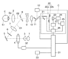
図1は眼科撮影装置として実施例1の眼底カメラの構成図を示している。この眼底カメラは無散瞳型の眼底カメラであり、眼底カメラの後方に撮影カメラCが取り付けられている。眼底カメラの眼底照明光学系O1である観察用光源1から、被検眼Eに対向する対物レンズ2に至る光路上には、コンデンサレンズ3、撮影用光源4、ミラー5、リング状の開口を有する絞り6、リレーレンズ7、孔あきミラー8が順次に配列されている。
FIG. 1 shows a block diagram of a fundus camera of
孔あきミラー8の透過方向の眼底撮影光学系O2の光路上には、合焦レンズ9、撮影レンズ10、跳ね上げミラー11、撮影カメラCが配列されている。ここで、観察用光源1は赤外光を射出するLED光源であり、跳ね上げミラー11は赤外光を透過し、可視光を反射する機能を有している。また、跳ね上げミラー11の反射方向には、被検眼Eの固視を誘導するためのLED等の発光部材を整列して配置した内部固視灯12が配置されている。
On the optical path of the fundus photographing optical system O2 in the transmission direction of the perforated mirror 8, a focusing
一方、孔あきミラー8の前面には、図示は省略しているが、アライメント指標のLED光源と、その光束を導くライトガイドの出射端が配置されており、被検眼Eの角膜面にアライメント指標を投影するアライメント用指標投影系が設けられている。同様に、図示は省略しているが、眼底照明光学系O1の光路内には、被検眼Eの眼底Erにフォーカス指標を投影するフォーカス用指標投影系が設けられている。 On the other hand, although not shown, an LED light source for an alignment index and an exit end of a light guide for guiding the luminous flux are arranged on the front surface of the perforated mirror 8, and the alignment index is arranged on the cornea surface of the eye E to be examined. An alignment index projection system for projecting is provided. Similarly, although not shown, a focus index projection system for projecting a focus index onto the fundus Er of the eye E is provided in the optical path of the fundus illumination optical system O1.
背景技術でも述べたように、本実施例の撮影カメラCは、一眼レフタイプのデジタルカメラであり、上述した眼底カメラに付設され、更に取り外し可能な構成とされている。眼底撮影光学系O2の撮影カメラC内の光路の延長上には、跳ね上げミラー21、露光状態を制御するためのシャッタ幕22の先幕22a及び後幕22b、撮像素子23が配列されている。
As described in the background art, the photographing camera C of the present embodiment is a single-lens reflex digital camera, and is attached to the above-described fundus camera and further configured to be removable. On the extension of the optical path in the photographing camera C of the fundus photographing optical system O2, a flip-
また、撮影カメラC内では、撮像素子23の出力は動画像生成部24を介してLCD等から成る動画観察モニタ25に接続され、更に撮影カメラCの制御を行う撮影カメラ制御部26に接続されている。また、撮影カメラ制御部26の出力は電子シャッタ制御を行う電子シャッタ制御部27を介して撮像素子23、ミラー21、シャッタ幕22に接続されている。
In the photographing camera C, the output of the
また、眼底カメラには眼底カメラ全体の制御を行うシステム制御部31が内蔵され、システム制御部31は撮影カメラCの撮影カメラ制御部26と接続されている。システム制御部31の出力は跳ね上げミラー11に接続され、また撮影光源制御部32を介して撮影用光源4に接続されている。また、システム制御部31には撮影開始スイッチを備え、被検眼Eの静止画撮影を実行する入力部33の出力が接続されている。
The fundus camera incorporates a
アライメント時には、観察用光源1を出射した赤外光は、コンデンサレンズ3、撮影用光源4を経てミラー5で反射される。ミラー5での反射光は、絞り6、リレーレンズ7を通り、孔あきミラー8の周辺で反射し、対物レンズ2、被検眼Eの瞳Epを通り眼底Erを照明する。そして、眼底Erでの赤外反射光は、瞳Ep、対物レンズ2、孔あきミラー8の孔を通り、合焦レンズ9、撮影レンズ10、赤外光を透過する跳ね上げミラー11を透過し、撮影カメラCの撮像素子23上に結像する。
At the time of alignment, the infrared light emitted from the
このように、観察用光源1から出射した赤外光は、眼底Erで反射されて眼底像として撮像素子23上に結像し、動画観察モニタ25上で動画として観察ができる。撮影カメラCにおけるこの観察状態はライブビュー状態そのものである。
As described above, the infrared light emitted from the observation
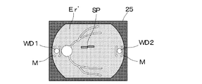
一方、図示しないアライメント用指標投影系及びフォーカス用指標投影系から発せられた光束は、それぞれ被検眼Eの眼底Erと角膜面で反射され、撮像素子23上に結像する。図2に示す動画観察モニタ25上で、眼底Erの観察像Er’と共に、アライメント指標WD1、WD2及びフォーカス指標SPが表示され、観察可能となっている。検者はこのアライメント指標WD1、WD2がアライメント範囲Mに入り、2つのフォーカス指標SPが横に一直線となるように、被検眼Eと眼底カメラの位置合わせを行うと共に、眼底Erに対するフォーカス合わせを行う。
On the other hand, light beams emitted from an alignment index projection system and a focus index projection system (not shown) are reflected by the fundus Er and the cornea surface of the eye E, respectively, and form an image on the
このとき、眼底Erからの反射像と、アライメント指標WD1、WD2、フォーカス指標SPを撮像素子23上に導光するために、撮影カメラCの跳ね上げミラー21は眼底撮影光学系O2の光路から退避している。また、先幕22aと後幕22bの機械シャッタ制御手段は開放状態とされている。この制御により、撮影カメラCの動画観察モニタ25を用いて、被検眼Eのアライメントを行うことが可能である。また、撮影カメラCにおけるこの制御によりライブビュー機能を達成している。
At this time, in order to guide the reflected image from the fundus oculi Er, the alignment indices WD1, WD2, and the focus index SP onto the
ここで、撮影カメラCのライブビュー機能を使用しない状態では、跳ね上げミラー21は眼底撮影光学系O2の光路中に挿入されている。また、先幕22aは遮光状態となっているため、眼底Erからの反射像と、アライメント指標WD1、WD2やフォーカス指標SPを撮像素子23上に導光することができない。
Here, in a state where the live view function of the photographing camera C is not used, the flip-up
図3(a)は静止画撮影時の動作のフローチャート図である。検者は被検眼Eのアライメントの終了後に、入力部33の撮影開始スイッチを押す。この開始信号によりシステム制御部31は、ステップS1の処理を行い撮影制御を開始する。ステップS2で、システム制御部31は撮影用光源4からの可視光を撮像素子23に導光するために、跳ね上げミラー11を眼底撮影光学系O2から退避する。更に、静止画撮影時に不必要な光が写り込まないようにするため、観察用光源1、内部固視灯12、アライメント指標WD1、WD2、フォーカス指標SPの消灯を行う。
FIG. 3A is a flowchart of the operation during still image shooting. The examiner presses the imaging start switch of the
ステップS2のこの撮影準備制御が終了すると、システム制御部31はステップS3で、撮影カメラCに対する撮影開始制御を実行する。撮影カメラCではステップS3に応じて、図3(b)の撮影カメラCでのステップS11の撮影開始処理が実行されるが、この撮影カメラCの制御は後述する。
When this shooting preparation control in step S2 is completed, the
ステップS3の処理終了後に実行される眼底カメラでのステップS4の処理もシステム制御部31で実行され、電子シャッタ制御の終了時間が経過するまでこの処理を繰り返す。つまり、撮影カメラCの内部で行われる電子シャッタ制御が終了されるまでの待機処理である。次に、ステップS4の待機処理が終了すると、システム制御部31ではステップS5として、撮影光源制御部32に発光命令を出力し、撮影用光源4を発光させる。
The processing of step S4 in the fundus camera executed after the processing of step S3 is also executed by the
このようにして、撮影用光源4から発せられた可視光は、眼底照明光学系O1を通過した後に、被検眼Eの眼底Erで反射され、眼底反射像は眼底撮影光学系O2を通って撮像素子23に結像する。最後に、ステップS6ではステップS2で行った撮影準備制御とは逆工程の撮影終了制御を実行する。
In this way, visible light emitted from the
図3(b)のフローチャート図では、眼底カメラのステップS3の処理から、撮影カメラ制御部26への切換えによって、ステップS11の撮影開始処理が実行される。ステップS11の処理に続いて、ステップS12で撮影カメラ制御部26による撮影のための設定変更処理等が行われる。撮影カメラ制御部26は撮影準備処理であるステップS12の処理の終了後に、ステップS13で電子シャッタ制御部27に対して、電子シャッタ制御を実行させる。その後に、撮影カメラ制御部26はステップS14でシャッタ制御処理を実行し撮影制御を終了する。
In the flowchart of FIG. 3B, the photographing start process of step S11 is executed by switching from the process of step S3 of the fundus camera to the photographing
このように、眼底カメラと撮影カメラCのそれぞれの撮影制御において、ステップS5で実行される撮影用光源4の発光制御が、ステップS13の電子シャッタ制御とステップS14のシャッタ制御の間で行われる。
In this way, in each of the photographing control of the fundus camera and the photographing camera C, the light emission control of the photographing
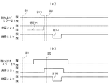
図4は撮影カメラCにおける撮影制御の様子のタイミングチャート図である。図中の開の表記は光路を遮断していない状態を表し、閉の表記は光路を遮断している状態を表している。また、跳ね上げミラー21、先幕22a、後幕22bの動作を示しており、各ステップSは図3(a)、(b)のフローチャート図で説明した処理が行われる工程を示している。
FIG. 4 is a timing chart showing the state of photographing control in the photographing camera C. In the figure, an open notation represents a state where the optical path is not blocked, and a closed notation represents a state where the optical path is blocked. Further, the operations of the flip-up
縦の点線で示している電子シャッタ制御は、ステップS1の撮影開始の後に、ステップS13のタイミングで実行され、シャッタ制御はステップS14のタイミングで実行されており、ステップS5の発光制御はステップS13とS14の間で実行される。 The electronic shutter control indicated by the vertical dotted line is executed at the timing of step S13 after the start of photographing in step S1, the shutter control is executed at the timing of step S14, and the light emission control of step S5 is the same as step S13. It is executed during S14.
このように、電子シャッタ制御の直前までに撮像素子23に受光された光は、ステップS13の電子シャッタ制御でリフレッシュされ、ステップS14のシャッタ制御終了後に静止画として記録される。つまり、ステップS5によって撮影用光源4から発光された眼底Erの反射像のみが、撮像素子23に蓄積され、静止画として記録可能となる。
Thus, the light received by the
図4(a)のように、ステップS1〜S14が実行されるまで、跳ね上げミラー21、先幕22a、後幕22bは全て開の状態となっている。即ち、特長的な第1動画観察手段で説明したライブビュー機能を使用したまま、ステップS5で発光制御を行うことである。この制御が本実施例の特長的な制御であることは、次の図4(b)と比較すると明らかである。
As shown in FIG. 4A, the flip-up
図4(b)はライブビュー機能を使用していない場合における撮影制御のタイミングチャート図である。図4(a)との違いは、ステップS1〜S14が実行されるまでの間に、跳ね上げミラー21、先幕22aが、それぞれ閉の状態から開の状態になっていることである。通常では、撮影カメラCのシャッタ幕22の開放信号であるX接点信号は、先幕22aが閉の状態から開の状態になった状態で出力され、このX接点信号に同期してステップS5で発光制御が行われる。
FIG. 4B is a timing chart of shooting control when the live view function is not used. The difference from FIG. 4A is that the flip-up
このように、図4(b)で行われる先幕22aが閉の状態から開の状態にする制御を、図4(a)ではステップS13の電子シャッタ制御で代用している。つまり、先幕22aが閉の状態から開の状態とする動きを、ステップS13の電子シャッタ制御によって達成していることになる。従って、電子シャッタ制御の直前までに撮像素子23に受光された光は、ステップS13の実行後にリフレッシュされ、ステップS5で撮影用光源4から発光された眼底Erの反射光のみが撮像素子23に蓄積され、静止画として記録される。
In this way, the control performed in FIG. 4B for changing the
また、図4(a)中に記載の処理Hは、第1動画観察手段で説明したライブビュー機能を使用した状態から、図4(b)で説明した先幕22aを用いた撮影制御を行う場合に、追加される処理である。しかし、この処理Hは図4(a)で明らかなように不要な処理である。また、この先幕22aの処理Hによっては、ステップS1〜S5までの時間を要する場合もあり、この時間によって、被検眼Eの固視位置が動いたり瞬きが発生する可能性もある。
Further, the process H described in FIG. 4A performs shooting control using the
このように、処理Hを行わないことで、撮影開始操作をしてから実際に撮影が実行されるまでの時間を最小限にし、撮影の瞬間に被検眼Eの固視位置が動いたり瞬きが発生することを防ぐことができ、撮影の失敗を防止している。 In this way, by not performing the process H, the time from the start of the shooting operation until the actual shooting is performed is minimized, and the fixation position of the eye E moves or blinks at the moment of shooting. It is possible to prevent this from happening, and to prevent shooting failures.
実施例1における眼底カメラは無散瞳型の眼底カメラであり、被検眼Eが眩しさを感じない近赤外光を用いて、撮影カメラCの動画観察モニタ25で観察している。従って、観察に十分な画像が得られると共に、被検眼Eに掛かる負荷を少なくできる。このように、無散瞳型の眼底カメラの特長を維持すると共に、撮影カメラCのような一般に使われるデジタルカメラを用いることができる。更に、そのライブビュー機能を観察に用いているので、観察を行うためのCCDなどの専用センサにより観察光学系を構成する必要がなく、装置を簡略化することが可能となる。 The fundus camera in the first embodiment is a non-mydriatic fundus camera, and is observed on the moving image observation monitor 25 of the photographing camera C using near-infrared light in which the eye E does not feel dazzling. Therefore, an image sufficient for observation can be obtained, and the load on the eye E can be reduced. Thus, while maintaining the features of the non-mydriatic fundus camera, a commonly used digital camera such as the photographing camera C can be used. Furthermore, since the live view function is used for observation, it is not necessary to configure an observation optical system with a dedicated sensor such as a CCD for performing observation, and the apparatus can be simplified.
図5は実施例2における散瞳型と無散瞳型の眼底カメラを一体化した散瞳・無散瞳一体型眼底カメラの構成図であり、実施例1と同じ符号の部材は同じ符号で示している。実施例1の図1に対し、眼底照明光学系O1内のコンデンサレンズ3と撮影用光源4の間に、赤外カットフィルタ41、可視カットフィルタ42が追加され、内部固視灯12の光路内に挿脱可能な反射ミラー43、直視ファインダ44が設けられている。
FIG. 5 is a configuration diagram of a mydriatic / non-mydriatic integrated fundus camera in which the mydriatic and non-mydriatic fundus cameras in the second embodiment are integrated, and members having the same reference numerals as those in the first embodiment are denoted by the same reference numerals. Show. Compared to FIG. 1 of the first embodiment, an
赤外カットフィルタ41と可視カットフィルタ42は、択一的に光路内挿脱に可能とされている。また、反射ミラー43は跳ね上げミラー11と内部固視灯12の間に設けられ、検者が可視光により被検眼Eのファインダ観察が可能な直視ファインダ44に導光可能となっている。
The
入力部33’は実施例1と機能的に異なっており、撮影開始スイッチに加えて、散瞳モードと無散瞳モードとの観察状態切換えのための散瞳・無散瞳選択スイッチが設けられている。また、観察用光源1については、実施例1では赤外光を射出するLEDとしたが、本実施例2では可視光を出射するハロゲンランプとされている。
The
この実施例2では、最初に入力部33’に設けられた散瞳・無散瞳選択スイッチを操作し、散瞳モードと無散瞳モードの切換え選択を行う。挿脱可能な反射ミラー43は、跳ね上げミラー11の反射方向の光路から離脱されており、可視カットフィルタ42が眼底照明光学系O1に挿入されている。
In the second embodiment, first, the mydriatic / non-mydriatic selection switch provided in the
観察用光源1を出射した可視光は、コンデンサレンズ3を通り、可視カットフィルタ42によって赤外光のみが透過される。可視カットフィルタ42を透過した赤外光は、撮影用光源4を通り、ミラー5で反射される。以下、撮像素子23上に結像するまでは、実施例1と同様である。
The visible light emitted from the observation
従って、観察用光源1から出射した可視光は赤外光のみとなって、眼底Erで反射された後に撮像素子23上に結像し、動画観察モニタ25上に動画による眼底像Er’として観察でき、実施例1と同様にアライメントを行うことができる。ここで、挿脱可能な反射ミラー43は、跳ね上げミラー11の反射方向の光路から離脱し、内部固視灯12からの光を被検眼Eに導光しながら、直視ファインダ44により観察可能となる。
Accordingly, the visible light emitted from the observation
また、撮影制御は実施例1と同様の制御であり、その効果も同様である。つまり、無散瞳モードでは動画観察モニタ25による第1動画観察手段による観察を行い、静止画撮影時には電子シャッタ制御部27による電子シャッタ処理を行うようになっている。
The photographing control is the same as that in the first embodiment, and the effect is the same. That is, in the non-mydriatic mode, observation is performed by the first moving image observation means by the moving
散瞳モードを選択すると、図6に示すように挿脱可能な反射ミラー43は、跳ね上げミラー11の反射方向の光路に挿入され、赤外カットフィルタ41は眼底照明光学系O1に挿入される。観察用光源1を出射した可視光はコンデンサレンズ3を通り、赤外カットフィルタ41によって赤外光成分がカットされ透過される。
When the mydriatic mode is selected, the
眼底Erの眼底像は対物レンズ2、合焦レンズ9、撮影レンズ10を経て跳ね上げミラー11に戻るが、跳ね上げミラー11は可視光を反射するため、眼底像反射ミラー43の方向に反射され、直視ファインダ44による第2動画観察手段によって観察できる。このように、実施例1と異なり可視光を用いた検者により直視観察を行い、被検眼Eのアライメントを行うことが可能である。
The fundus image of the fundus Er returns to the flip-up
また、撮影制御は実施例1で説明した図4(b)の制御と同様になる。この場合の撮影制御については、撮影カメラCを用いた一般的な撮影方法である。つまり、散瞳モードでは直視ファインダ44で観察を行い、撮影時には先幕22aを用いた撮影制御を行う。
Further, the shooting control is the same as the control of FIG. 4B described in the first embodiment. The shooting control in this case is a general shooting method using the shooting camera C. That is, in the mydriatic mode, observation is performed with the
このように実施例2における制御は、散瞳モードと無散瞳モードの選択に応じて、無散瞳モードでは動画観察モニタ25で観察し、電子シャッタ処理を用いた撮影制御を行い、散瞳モードでは直視ファインダ44で観察し、先幕22aを用いた撮影制御を行う。
As described above, the control in the second embodiment is based on the selection of the mydriatic mode and the non-mydriatic mode. In the non-mydriatic mode, the observation is performed on the moving
実施例2の眼底カメラは、実施例1で説明した無散瞳型の眼底カメラと同様の制御を無散瞳モードで行うことにより、実施例1と同様に観察を行うためのCCDなどの専用センサ、観察光学系を必要とせず、装置を簡略化することができる。特に実施例2のように、散瞳モードと無散瞳モードの両方の機能を有する装置は一般に複雑化が免れないため、その効果は大きい。更に、実施例1と同様に、撮影開始操作をしてから実際に撮影が実行されるまでの時間を最小限にし、撮影の瞬間に被検眼の固視位置が動いたり瞬きが発生することを防ぐことが可能となり、撮影の失敗を防止できる。 The fundus camera of the second embodiment performs a control similar to that of the non-mydriatic fundus camera described in the first embodiment in the non-mydriatic mode, so that a dedicated CCD or the like for performing observation in the same manner as in the first embodiment. A sensor and an observation optical system are not required, and the apparatus can be simplified. In particular, as in the second embodiment, an apparatus having functions of both the mydriatic mode and the non-mydriatic mode generally has a great effect because it cannot be complicated. Further, as in the first embodiment, the time from the start of shooting operation until the actual shooting is performed is minimized, and the fixation position of the eye to be inspected or blinking occurs at the moment of shooting. This makes it possible to prevent shooting failures.
C 撮影カメラ
22a 先幕
22b 後幕
23 撮像素子
25 動画観察モニタ
26 撮影カメラ制御部
27 電子シャッタ制御部
31 システム制御部
Claims (17)
前記照明光学系を介して被検眼に照明する赤外光を発生させるための第1の光源を消灯した後に、前記撮像手段で受光した光に基づく電荷をリフレッシュし、前記照明光学系を介して前記被検眼に照明する可視光を発生させるための第2の光源を発光させる制御手段と、
を有することを特徴とする眼科撮影装置。 A fundus camera body comprising: an illumination optical system that illuminates the eye to be examined; and a photographing optical system that photographs the eye to be examined illuminated with either infrared light or visible light by the illumination optical system; and the photographing optical system An ophthalmologic photographing apparatus comprising an imaging means having a light receiving surface for receiving return light from the eye to be examined via the camera and detachable from the fundus camera body,
After turning off the first light source for generating the infrared light that illuminates the eye through the illumination optical system, to refresh the charge based on the light received by the image pickup means, through the illumination optical system Control means for emitting a second light source for generating visible light to illuminate the eye to be examined ;
An ophthalmologic photographing apparatus comprising:
前記制御手段が、前記開始スイッチの押下に応じて、前記眼底カメラ本体に設けられた前記被検眼に指標を投影する指標投影手段の光源と前記第1の光源とを消灯し、前記撮像手段で受光した光に基づく電荷をリフレッシュすることを特徴とする請求項1あるいは2に記載の眼科撮影装置。 A start switch for starting still image shooting of the eye to be examined with the visible light;
The control means turns off the light source of the index projection means for projecting the index on the eye to be examined and the first light source provided in the fundus camera body in response to pressing of the start switch , and the imaging means 3. The ophthalmologic photographing apparatus according to claim 1, wherein the charge based on the received light is refreshed.
前記選択手段により前記無散瞳モードが選択された場合、前記照明光学系を介して前記赤外光を照明した前記被検眼からの戻り光が結像した前記撮像手段からの出力信号に基づいて、前記カメラに設けられた表示手段に前記被検眼の動画像を表示させる表示制御手段と、を有し、When the non-mydriatic mode is selected by the selection means, based on an output signal from the imaging means on which the return light from the eye to be examined that has illuminated the infrared light via the illumination optical system is imaged Display control means for displaying a moving image of the eye to be examined on display means provided in the camera,
前記制御手段が、前記選択手段により前記無散瞳モードが選択された場合、前記カメラに設けられた先幕の機械シャッタを開けることを特徴とする請求項1乃至4のいずれか1項に記載の眼科撮影装置。The said control means opens the mechanical shutter of the front curtain provided in the said camera, when the said non-mydriatic mode is selected by the said selection means, The any one of Claim 1 thru | or 4 characterized by the above-mentioned. Ophthalmic photography device.
前記制御手段が、前記選択手段により前記無散瞳モードが選択された場合、前記反射部材を前記光路から外すことを特徴とする請求項5に記載の眼科撮影装置。6. The ophthalmologic photographing apparatus according to claim 5, wherein when the non-mydriatic mode is selected by the selection unit, the control unit removes the reflecting member from the optical path.
前記照明光学系を介して被検眼に照明する赤外光を発生させるための第1の光源を消灯した後に、且つ前記照明光学系を介して前記被検眼に照明する可視光を発生させるための第2の光源を発光させる前に、前記撮像手段で受光した光に基づく電荷をリフレッシュする制御手段と、
を備えることを特徴とするカメラ。 It can be attached to and detached from a fundus camera body including an illumination optical system that illuminates the eye to be examined, and an imaging optical system that photographs the eye to be examined that is illuminated with either infrared light or visible light by the illumination optical system , A camera comprising imaging means having a light receiving surface for receiving return light from the eye to be examined through the imaging optical system ;
After turning off the first light source for generating the infrared light that illuminates the eye through the illumination optical system, and for generating visible light for illuminating the subject's eye via the illumination optical system Control means for refreshing charges based on light received by the imaging means before causing the second light source to emit light ;
The provided camera according to claim Rukoto.
前記制御手段が、前記第2の光源の発光に応じて、前記後幕の機械シャッタを閉じて、前記撮像手段から電荷を読み出すことを特徴とする請求項9に記載のカメラ。 Equipped with a rear curtain of the mechanical shutter,
It said control means, in response to said light emission of the second light source, a mechanical shutter of the rear curtain closes, camera according to claim 9, characterized in that reading charges from the imaging means.
無散瞳モードの場合、前記照明光学系を介して前記赤外光を照明した前記被検眼からの戻り光が結像した前記撮像手段からの出力信号に基づいて、前記被検眼の動画像を表示する表示手段と、を備え、In the case of the non-mydriatic mode, a moving image of the eye to be examined is obtained based on an output signal from the imaging unit on which the return light from the eye to be examined that has illuminated the infrared light through the illumination optical system is imaged. Display means for displaying,
前記制御手段が、前記無散瞳モードの場合、前記先幕の機械シャッタを開けることを特徴とする請求項9あるいは10に記載のカメラ。11. The camera according to claim 9, wherein when the control unit is in the non-mydriatic mode, the mechanical shutter of the front curtain is opened.
前記制御手段が、前記無散瞳モードの場合、前記反射部材を前記光路から外すことを特徴とする請求項11に記載のカメラ。The camera according to claim 11, wherein the control unit removes the reflecting member from the optical path in the non-mydriatic mode.
前記照明光学系を介して被検眼に照明する赤外光を発生させるための第1の光源を消灯した後に、前記受光面で受光した光に基づく電荷をリフレッシュし、前記照明光学系を介して前記被検眼に照明する可視光を発生させるための第2の光源を発光させる制御装置と、After turning off the first light source for generating infrared light that illuminates the eye to be examined through the illumination optical system, the charge based on the light received by the light receiving surface is refreshed, and the light is transmitted through the illumination optical system. A control device that emits a second light source for generating visible light that illuminates the eye to be examined; and
を有することを特徴とする眼科システム。An ophthalmic system characterized by comprising:
Priority Applications (3)
| Application Number | Priority Date | Filing Date | Title |
|---|---|---|---|
| JP2009196997A JP4995244B2 (en) | 2009-08-27 | 2009-08-27 | Ophthalmic imaging equipment |
| US12/857,876 US8449112B2 (en) | 2009-08-27 | 2010-08-17 | Ophthalmologic imaging apparatus and ophthalmologic imaging method |
| US13/873,062 US9033501B2 (en) | 2009-08-27 | 2013-04-29 | Ophthalmologic imaging apparatus and ophthalmologic imaging method |
Applications Claiming Priority (1)
| Application Number | Priority Date | Filing Date | Title |
|---|---|---|---|
| JP2009196997A JP4995244B2 (en) | 2009-08-27 | 2009-08-27 | Ophthalmic imaging equipment |
Related Child Applications (1)
| Application Number | Title | Priority Date | Filing Date |
|---|---|---|---|
| JP2012103802A Division JP5669109B2 (en) | 2012-04-27 | 2012-04-27 | Ophthalmologic photographing apparatus, camera detachably attachable to fundus camera body, and method for controlling ophthalmic photographing apparatus |
Publications (3)
| Publication Number | Publication Date |
|---|---|
| JP2011045552A JP2011045552A (en) | 2011-03-10 |
| JP2011045552A5 JP2011045552A5 (en) | 2011-09-22 |
| JP4995244B2 true JP4995244B2 (en) | 2012-08-08 |
Family
ID=43624442
Family Applications (1)
| Application Number | Title | Priority Date | Filing Date |
|---|---|---|---|
| JP2009196997A Expired - Fee Related JP4995244B2 (en) | 2009-08-27 | 2009-08-27 | Ophthalmic imaging equipment |
Country Status (2)
| Country | Link |
|---|---|
| US (2) | US8449112B2 (en) |
| JP (1) | JP4995244B2 (en) |
Families Citing this family (8)
| Publication number | Priority date | Publication date | Assignee | Title |
|---|---|---|---|---|
| US20150021228A1 (en) | 2012-02-02 | 2015-01-22 | Visunex Medical Systems Co., Ltd. | Eye imaging apparatus and systems |
| US9655517B2 (en) | 2012-02-02 | 2017-05-23 | Visunex Medical Systems Co. Ltd. | Portable eye imaging apparatus |
| US9351639B2 (en) | 2012-03-17 | 2016-05-31 | Visunex Medical Systems Co. Ltd. | Eye imaging apparatus with a wide field of view and related methods |
| JP2014094162A (en) * | 2012-11-09 | 2014-05-22 | Canon Inc | Ophthalmologic imaging device |
| JP6049608B2 (en) * | 2013-12-27 | 2016-12-21 | キヤノン株式会社 | IMAGING DEVICE, IMAGING DEVICE CONTROL METHOD, PROGRAM, AND RECORDING MEDIUM |
| US9986908B2 (en) | 2014-06-23 | 2018-06-05 | Visunex Medical Systems Co. Ltd. | Mechanical features of an eye imaging apparatus |
| US9814386B2 (en) | 2014-07-02 | 2017-11-14 | IDx, LLC | Systems and methods for alignment of the eye for ocular imaging |
| EP3250106A4 (en) | 2015-01-26 | 2019-01-02 | Visunex Medical Systems Co. Ltd. | A disposable cap for an eye imaging apparatus and related methods |
Family Cites Families (9)
| Publication number | Priority date | Publication date | Assignee | Title |
|---|---|---|---|---|
| JPH06125877A (en) * | 1992-09-01 | 1994-05-10 | Topcon Corp | Device for photographing corneal endotheliocyte |
| JPH0966030A (en) * | 1995-09-01 | 1997-03-11 | Kowa Co | Fundus camera |
| JPH09308610A (en) * | 1996-05-24 | 1997-12-02 | Canon Inc | Ophthalmologic photographing device |
| JP2001292371A (en) * | 2000-04-05 | 2001-10-19 | Furoobell:Kk | Imaging control apparatus, its method and recording medium |
| JP2003210409A (en) * | 2002-01-23 | 2003-07-29 | Canon Inc | Fundus camera |
| US7290882B2 (en) * | 2004-02-05 | 2007-11-06 | Ocutronics, Llc | Hand held device and methods for examining a patient's retina |
| DE602006021098D1 (en) * | 2005-06-15 | 2011-05-19 | Seiko Epson Corp | Digital camera and control method for it |
| JP4901230B2 (en) * | 2006-02-08 | 2012-03-21 | 興和株式会社 | Imaging system |
| JP2008142233A (en) * | 2006-12-08 | 2008-06-26 | Canon Inc | Ophthalmologic imaging apparatus |
-
2009
- 2009-08-27 JP JP2009196997A patent/JP4995244B2/en not_active Expired - Fee Related
-
2010
- 2010-08-17 US US12/857,876 patent/US8449112B2/en active Active
-
2013
- 2013-04-29 US US13/873,062 patent/US9033501B2/en not_active Expired - Fee Related
Also Published As
| Publication number | Publication date |
|---|---|
| US20130242260A1 (en) | 2013-09-19 |
| US9033501B2 (en) | 2015-05-19 |
| JP2011045552A (en) | 2011-03-10 |
| US20110051085A1 (en) | 2011-03-03 |
| US8449112B2 (en) | 2013-05-28 |
Similar Documents
| Publication | Publication Date | Title |
|---|---|---|
| US11813024B2 (en) | Hand-held portable fundus camera for screening photography | |
| JP4995244B2 (en) | Ophthalmic imaging equipment | |
| US7798642B2 (en) | Fundus camera | |
| JP4901230B2 (en) | Imaging system | |
| JP5430260B2 (en) | Ophthalmic imaging apparatus and ophthalmic imaging method | |
| US9386919B2 (en) | Ophthalmic photographing apparatus and method of controlling the same | |
| JP5665281B2 (en) | Ophthalmic imaging equipment | |
| JP5328568B2 (en) | Ophthalmic imaging equipment | |
| JP2014073205A (en) | Ophthalmographic device | |
| JP2005261447A (en) | Ophthalmologic photographing apparatus | |
| JP5669109B2 (en) | Ophthalmologic photographing apparatus, camera detachably attachable to fundus camera body, and method for controlling ophthalmic photographing apparatus | |
| JP2002051985A (en) | Fundus camera | |
| JP2003210409A (en) | Fundus camera | |
| JP2000107134A (en) | Ophthalmologic imaging apparatus | |
| JP5383285B2 (en) | Ophthalmic apparatus and control method thereof | |
| JP3526959B2 (en) | Fundus camera | |
| JP4659173B2 (en) | Fundus camera | |
| JP5755200B2 (en) | Ophthalmic imaging apparatus and method | |
| JPH09271464A (en) | Ophthalmological device | |
| JP2014226370A (en) | Ophthalmic photographing apparatus | |
| JP2005095382A (en) | Ophthalmologic photographing device |
Legal Events
| Date | Code | Title | Description |
|---|---|---|---|
| A521 | Request for written amendment filed |
Free format text: JAPANESE INTERMEDIATE CODE: A523 Effective date: 20110809 |
|
| A621 | Written request for application examination |
Free format text: JAPANESE INTERMEDIATE CODE: A621 Effective date: 20110809 |
|
| A977 | Report on retrieval |
Free format text: JAPANESE INTERMEDIATE CODE: A971007 Effective date: 20111213 |
|
| A131 | Notification of reasons for refusal |
Free format text: JAPANESE INTERMEDIATE CODE: A131 Effective date: 20120110 |
|
| A521 | Request for written amendment filed |
Free format text: JAPANESE INTERMEDIATE CODE: A523 Effective date: 20120309 |
|
| TRDD | Decision of grant or rejection written | ||
| A01 | Written decision to grant a patent or to grant a registration (utility model) |
Free format text: JAPANESE INTERMEDIATE CODE: A01 Effective date: 20120410 |
|
| A01 | Written decision to grant a patent or to grant a registration (utility model) |
Free format text: JAPANESE INTERMEDIATE CODE: A01 |
|
| A61 | First payment of annual fees (during grant procedure) |
Free format text: JAPANESE INTERMEDIATE CODE: A61 Effective date: 20120509 |
|
| FPAY | Renewal fee payment (event date is renewal date of database) |
Free format text: PAYMENT UNTIL: 20150518 Year of fee payment: 3 |
|
| R151 | Written notification of patent or utility model registration |
Ref document number: 4995244 Country of ref document: JP Free format text: JAPANESE INTERMEDIATE CODE: R151 |
|
| FPAY | Renewal fee payment (event date is renewal date of database) |
Free format text: PAYMENT UNTIL: 20150518 Year of fee payment: 3 |
|
| LAPS | Cancellation because of no payment of annual fees |