JP4994248B2 - Target acquisition and overlay measurement based on imaging with two diffraction orders - Google Patents
Target acquisition and overlay measurement based on imaging with two diffraction orders Download PDFInfo
- Publication number
- JP4994248B2 JP4994248B2 JP2007558164A JP2007558164A JP4994248B2 JP 4994248 B2 JP4994248 B2 JP 4994248B2 JP 2007558164 A JP2007558164 A JP 2007558164A JP 2007558164 A JP2007558164 A JP 2007558164A JP 4994248 B2 JP4994248 B2 JP 4994248B2
- Authority
- JP
- Japan
- Prior art keywords
- target
- targets
- periodic
- beams
- sine wave
- Prior art date
- Legal status (The legal status is an assumption and is not a legal conclusion. Google has not performed a legal analysis and makes no representation as to the accuracy of the status listed.)
- Active
Links
Images


Classifications
-
- G—PHYSICS
- G03—PHOTOGRAPHY; CINEMATOGRAPHY; ANALOGOUS TECHNIQUES USING WAVES OTHER THAN OPTICAL WAVES; ELECTROGRAPHY; HOLOGRAPHY
- G03F—PHOTOMECHANICAL PRODUCTION OF TEXTURED OR PATTERNED SURFACES, e.g. FOR PRINTING, FOR PROCESSING OF SEMICONDUCTOR DEVICES; MATERIALS THEREFOR; ORIGINALS THEREFOR; APPARATUS SPECIALLY ADAPTED THEREFOR
- G03F9/00—Registration or positioning of originals, masks, frames, photographic sheets or textured or patterned surfaces, e.g. automatically
- G03F9/70—Registration or positioning of originals, masks, frames, photographic sheets or textured or patterned surfaces, e.g. automatically for microlithography
- G03F9/7049—Technique, e.g. interferometric
-
- G—PHYSICS
- G03—PHOTOGRAPHY; CINEMATOGRAPHY; ANALOGOUS TECHNIQUES USING WAVES OTHER THAN OPTICAL WAVES; ELECTROGRAPHY; HOLOGRAPHY
- G03F—PHOTOMECHANICAL PRODUCTION OF TEXTURED OR PATTERNED SURFACES, e.g. FOR PRINTING, FOR PROCESSING OF SEMICONDUCTOR DEVICES; MATERIALS THEREFOR; ORIGINALS THEREFOR; APPARATUS SPECIALLY ADAPTED THEREFOR
- G03F7/00—Photomechanical, e.g. photolithographic, production of textured or patterned surfaces, e.g. printing surfaces; Materials therefor, e.g. comprising photoresists; Apparatus specially adapted therefor
- G03F7/70—Microphotolithographic exposure; Apparatus therefor
- G03F7/70483—Information management; Active and passive control; Testing; Wafer monitoring, e.g. pattern monitoring
- G03F7/70605—Workpiece metrology
- G03F7/70616—Monitoring the printed patterns
- G03F7/70633—Overlay, i.e. relative alignment between patterns printed by separate exposures in different layers, or in the same layer in multiple exposures or stitching
-
- G—PHYSICS
- G03—PHOTOGRAPHY; CINEMATOGRAPHY; ANALOGOUS TECHNIQUES USING WAVES OTHER THAN OPTICAL WAVES; ELECTROGRAPHY; HOLOGRAPHY
- G03F—PHOTOMECHANICAL PRODUCTION OF TEXTURED OR PATTERNED SURFACES, e.g. FOR PRINTING, FOR PROCESSING OF SEMICONDUCTOR DEVICES; MATERIALS THEREFOR; ORIGINALS THEREFOR; APPARATUS SPECIALLY ADAPTED THEREFOR
- G03F9/00—Registration or positioning of originals, masks, frames, photographic sheets or textured or patterned surfaces, e.g. automatically
- G03F9/70—Registration or positioning of originals, masks, frames, photographic sheets or textured or patterned surfaces, e.g. automatically for microlithography
- G03F9/7088—Alignment mark detection, e.g. TTR, TTL, off-axis detection, array detector, video detection
Description
本発明は、一般に、半導体製造処理で利用される測定技術および検査技術に関し、特に、ウエハターゲットを取得して、半導体ウエハ積層体において、異なる層または同じ層上の異なるパターンの間のアライメント誤差を測定するための技術に関する。 The present invention relates generally to measurement and inspection techniques utilized in semiconductor manufacturing processes, and more particularly to acquiring wafer targets to reduce alignment errors between different layers or different patterns on the same layer in a semiconductor wafer stack. It relates to a technique for measuring.
ターゲットの取得は、半導体の光学検査および測定の際に最もよく利用される処理の1つである。半導体処理を試験するための検査または測定のレシピごとに、ターゲットへの正確な誘導と、検査すべき形状の特定および取得とが必要になる。現在、ターゲットの取得は、通例、実際の検査または測定動作が実行される位置に隣接してウエハの層と共にプリントされた特別な取得パターンによって実行される。これら取得パターンの画像は、画像化ツールによって取り込まれ、その後、解析アルゴリズムを用いて、取り込まれた画像が取得パターンを含むことを確認し、実際のウエハ上でのターゲット画像の座標を算出する。 Target acquisition is one of the most commonly used processes in optical inspection and measurement of semiconductors. Each inspection or measurement recipe for testing semiconductor processing requires accurate guidance to the target and identification and acquisition of the shape to be inspected. Currently, target acquisition is typically performed by a special acquisition pattern printed with the layer of the wafer adjacent to the location where the actual inspection or measurement operation is performed. These acquired pattern images are captured by an imaging tool, and thereafter, using an analysis algorithm, it is confirmed that the captured image includes the acquired pattern, and the coordinates of the target image on the actual wafer are calculated.
ウエハにおけるオーバレイおよびアライメントの誤差の測定は、集積回路および素子の製造において用いられる最も重要なプロセス制御技術の1つである。オーバレイ精度は、一般に、第1のパターン層が、その上または下に配置された第2のパターン層に対してどれだけ正確に整列しているかを判断することに関する。アライメント誤差は、第1のパターンが、同じ層に配置された第2のパターンに対してどれだけ正確に整列しているかを判断することに関する。これらの用語、すなわち、オーバレイおよびアライメントは、本明細書では、交換可能に用いられている。現在、オーバレイおよびアライメントの測定は、ウエハの層と共にプリントされた試験パターンによって実行されている。これら試験パターンの画像は、画像化ツールによって取り込まれ、解析アルゴリズムを用いて、取り込まれた画像から、パターンの相対的な位置ずれが算出される。 Measuring overlay and alignment errors on a wafer is one of the most important process control techniques used in the manufacture of integrated circuits and devices. Overlay accuracy generally relates to determining how accurately a first pattern layer is aligned with a second pattern layer disposed above or below it. The alignment error relates to determining how accurately the first pattern is aligned with the second pattern placed on the same layer. These terms, overlay and alignment, are used interchangeably herein. Currently, overlay and alignment measurements are performed by test patterns printed along with the layers of the wafer. These test pattern images are captured by an imaging tool, and the relative positional deviation of the pattern is calculated from the captured images using an analysis algorithm.
従来技術では、入射ビームを対象物に向けるための光源を有する光学ツールによって、対象物が画像化される。ビームは、対象物によって反射および散乱され、CCD(電荷結合素子)カメラなどの画像センサに向かう。具体的には、対象物から複数の光線がもたらされる。次に、光線は、通例、レンズを通過した後に、特定の平面(像平面と呼ばれる)において対象物の画像を形成する。最小量のピンぼけ、すなわち、最大の鮮明さを有するターゲットの焦点画像を実現するには、CCDカメラは、この特定の像平面の位置に配置される必要がある。 In the prior art, an object is imaged by an optical tool having a light source for directing an incident beam onto the object. The beam is reflected and scattered by the object and is directed to an image sensor such as a CCD (Charge Coupled Device) camera. Specifically, a plurality of light beams are brought from the object. The light rays then typically form an image of the object in a particular plane (referred to as the image plane) after passing through the lens. In order to achieve a minimum amount of defocus, i.e. a focused image of the target with the maximum sharpness, the CCD camera needs to be placed at this particular image plane.
残念ながら、従来の機械的な移動機構では、取得動作やオーバレイ測定ごとに完全に最適な焦点位置にセンサを配置することは不可能である。すなわち、従来の方法の許容誤差では、取得動作またはオーバレイ測定ごとに最高の焦点を実現するために十分に正確な位置への移動を行うことが可能ではない。 Unfortunately, with conventional mechanical movement mechanisms, it is not possible to place the sensor at a perfectly optimal focus position for each acquisition operation or overlay measurement. That is, with the tolerances of conventional methods, it is not possible to move to a position that is sufficiently accurate to achieve the best focus for each acquisition operation or overlay measurement.
さらに、画像化システムの光学収差により、画像の配置誤差が生じる。オーバレイターゲットについては、これらの配置誤差は、第1の層からの散乱光と第2の層からの散乱光とに対して異なる。収差による配置誤差の差は、オーバレイ測定の誤差を引き起こす。この収差によるオーバレイ誤差を最小限に抑えるためには、光学系の光軸に沿ってオーバレイターゲットを正確にセンタリングする必要がある。 Furthermore, image placement errors are caused by optical aberrations of the imaging system. For overlay targets, these placement errors are different for scattered light from the first layer and scattered light from the second layer. Differences in placement errors due to aberrations cause errors in overlay measurements. In order to minimize the overlay error due to this aberration, it is necessary to accurately center the overlay target along the optical axis of the optical system.
したがって、ターゲット取得およびオーバレイ画像化のための機構の改良が求められている。さらに、画像センサの柔軟な配置(z)を実現するターゲット画像化機構が有用である。また、オーバレイターゲットの柔軟な配置(x,y)を実現するオーバレイ測定機構も有用である。 Therefore, there is a need for improved mechanisms for target acquisition and overlay imaging. Furthermore, a target imaging mechanism that realizes flexible placement (z) of the image sensor is useful. An overlay measurement mechanism that realizes flexible arrangement (x, y) of the overlay target is also useful.
したがって、光学画像化システムを用いて、ターゲット取得を判定するため、および、オーバレイまたはアライメント誤差を判定するための改良された機構が開示されている。一般に、そのシステムの照明は、特定の角度でのみ回折格子ターゲットに向けられ、結像レンズは、互いに干渉して正弦波画像を形成する対応した対の回折次数を捕捉するよう設定される。すなわち、結像レンズによって捕捉されるすべての光線が、画像化情報に利用される。一実施形態では、コヒーレントであるために、互いに干渉して正弦波画像を形成する0次および1次の回折次数の2つの対が用いられる。本発明の実施形態で画像化される出力ビームのすべてが、画像に寄与するため、DC背景ノイズが少なくなる。したがって、従来の他の型の画像化システムよりも、コントラストが改善される。オーバレイ測定の用途では、本発明の実施形態は、従来のオーバレイ判定技術および装置よりも、高い精度を有すると共に、光学収差への感受性が低いためにツール起因シフトが低減される。 Accordingly, an improved mechanism for determining target acquisition and determining overlay or alignment errors using an optical imaging system is disclosed. In general, the illumination of the system is directed at the diffraction grating target only at a particular angle, and the imaging lens is set to capture a corresponding pair of diffraction orders that interfere with each other to form a sinusoidal image. That is, all light rays captured by the imaging lens are used for imaging information. In one embodiment, to be coherent, two pairs of zeroth and first order diffraction orders are used that interfere with each other to form a sinusoidal image. All of the output beams imaged in embodiments of the present invention contribute to the image, thus reducing DC background noise. Thus, contrast is improved over other conventional types of imaging systems. In overlay measurement applications, embodiments of the present invention have higher accuracy and less tool-induced shifts due to less sensitivity to optical aberrations than conventional overlay determination techniques and apparatus.
本発明の原理を例示した添付図面との関連で行う以下の詳細な説明から、本発明の上述およびその他の特徴と利点がさらに詳しく示されている。 The foregoing and other features and advantages of the present invention will be more fully shown from the following detailed description, taken in conjunction with the accompanying drawings, illustrating by way of example the principles of the invention.
次に、本発明の具体的な実施形態について詳細に説明する。添付の図面には、この実施形態が例示されている。以下では、この具体的な実施形態を参照しつつ本発明を説明するが、本発明を一実施形態に限定する意図はない。逆に、添付の特許請求の範囲によって規定される本発明の趣旨および範囲内に含まれる代替物、変形物、および、均等物を網羅するよう意図されている。以下では、本発明を十分に理解できるよう、多くの具体的な詳細事項を説明する。しかしながら、本発明は、これらの詳細事項の一部または全てがなくとも実施可能である。そのほか、本発明が不必要に不明瞭となるのを避けるため、周知の処理動作については詳しく説明していない。 Next, specific embodiments of the present invention will be described in detail. This embodiment is illustrated in the accompanying drawings. The present invention will be described below with reference to this specific embodiment, but there is no intention to limit the present invention to one embodiment. On the contrary, the intent is to cover alternatives, modifications and equivalents included within the spirit and scope of the invention as defined by the appended claims. In the following description, numerous specific details are set forth in order to provide a thorough understanding of the present invention. However, the present invention may be practiced without some or all of these details. In other instances, well known processing operations have not been described in detail in order to avoid unnecessarily obscuring the present invention.
一般に、本発明の実施形態は、周期的な取得ターゲットまたはオーバレイターゲットから散乱され、波長、および、2つのビーム間の分離角度が、ターゲットのピッチにほぼ適合されて、ほぼ純粋な正弦波の画像を形成させるような2つの散乱ビームのみを用いて画像化を行うことにより、ターゲットの取得もしくはオーバレイ(または、アライメント)の判定を行うための機構を提供する。この正弦波画像の焦点深度は、非常に大きい。したがって、画像センサの位置は、柔軟であり、1つの像焦点面の位置に正確に配置される必要はない。すなわち、センサは、結像レンズの後ろの一連の複数の位置のいずれに配置されても、焦点の良好な像平面に存在することが可能である。以下の実施形態は、異なる層上の構造間でのオーバレイ誤差を判定するための技術に適用される例として説明されているが、これらの実施形態は、同じ層における2つの構造間のアライメント誤差を判定するための技術、または、同じ層における構造のターゲット取得のための技術にも適用可能である。 In general, embodiments of the present invention are scattered from a periodic acquisition target or overlay target, and the wavelength and separation angle between the two beams are approximately matched to the pitch of the target to provide a substantially pure sinusoidal image. Provides a mechanism for target acquisition or overlay (or alignment) determination by imaging using only two scattered beams to form The depth of focus of this sine wave image is very large. Therefore, the position of the image sensor is flexible and does not need to be accurately placed at the position of one image focal plane. That is, the sensor can be in an image plane with good focus regardless of the position of the series of multiple positions behind the imaging lens. The following embodiments are described as examples applied to techniques for determining overlay errors between structures on different layers, but these embodiments are alignment errors between two structures on the same layer. It can also be applied to a technique for determining a target or a technique for obtaining a target of a structure in the same layer.
2つのコヒーレントな平面波が干渉すると、その結果として生じる強度分布は、式1によって与えられる空間周期を有する。
When two coherent plane waves interfere, the resulting intensity distribution has a spatial period given by

ここで、θ1は、第1の波と像平面への垂線との間の角度分離であり、θ2は、第2の波と像平面への垂線との間の角度分離であり、λは、光の波長である。かかる2つのビームの干渉の結果として生じる画像は、周期(ピッチ)pを有する単純な正弦波である。 Where θ 1 is the angular separation between the first wave and the normal to the image plane, θ 2 is the angular separation between the second wave and the normal to the image plane, and λ Is the wavelength of light. The image resulting from the interference of such two beams is a simple sine wave with period (pitch) p.
2つの干渉するコヒーレントな平面波が、像平面への垂線に関して対象であり、それぞれ、波と像平面への垂線との間の角度分離が|θ|である場合には、式1は、式2のようになる。 If two interfering coherent plane waves are of interest with respect to the normal to the image plane and the angular separation between the wave and the normal to the image plane is | θ | become that way.
ここで、2θは、それらの波の間での角度分離であり、λは、光の波長である。この関係を図1に示す。2つの光線が干渉すると、結果として生じる画像は、正弦波になる。さらに、焦点深度が無限大になるため、結果として生じる正弦波画像は、一連の像平面にわたって形成される。図2に示すように、画像を形成する光線の間の相対位相は、焦点の変化に伴って変わることがない。したがって、理論的には、特定の深度または像平面に焦点を合わせる必要はなく、対象物から任意の深度に結像することができる。結果として、センサの位置が柔軟になり、対象物から任意の距離にセンサを配置することができる。 Where 2θ is the angular separation between those waves and λ is the wavelength of the light. This relationship is shown in FIG. When the two rays interfere, the resulting image becomes a sine wave. Furthermore, since the depth of focus is infinite, the resulting sinusoidal image is formed over a series of image planes. As shown in FIG. 2, the relative phase between the light rays forming the image does not change with a change in focus. Therefore, in theory, it is not necessary to focus on a specific depth or image plane, and an image can be formed at any depth from the object. As a result, the position of the sensor becomes flexible, and the sensor can be arranged at an arbitrary distance from the object.
しかしながら、実際には、ターゲットに当たる時に、入射ビームの角度およびスペクトルが両方とも拡散する。さらに、周期的なターゲットは、サイズが限定される。したがって、焦点深度は無限大ではないものの、特定の特性を有する2つの光束を用いて特定の特性を有するターゲットを画像化することにより、非常に大きい焦点深度を実現できる。その大きい焦点深度は、すべての平面を像平面として利用できる連続的な範囲を規定する。この連続的な範囲は、システムの焦点深度と呼ばれる。それは、画質(焦点)が良好である範囲(例えば、1ミクロン)である。 In practice, however, both the angle and the spectrum of the incident beam diffuse when hitting the target. Furthermore, the size of the periodic target is limited. Therefore, although the depth of focus is not infinite, a very large depth of focus can be realized by imaging a target having specific characteristics using two light beams having specific characteristics. Its large depth of focus defines a continuous range where all planes can be used as image planes. This continuous range is called the depth of focus of the system. It is a range (for example, 1 micron) where the image quality (focus) is good.
任意の適切な機構を用いて、ほぼ無限大の焦点深度で正弦波画像を生成してよい。一実施例では、正弦波画像を形成するために、2つの散乱平面波のみが、結像レンズによって捕捉されるように、軸外の入射平面波で画像化される周期的なターゲットが提供される。2つの散乱平面波のみが、画像の構築に用いられるように、周期的なターゲットが画像化された場合、結果として生じる正弦波画像は、ターゲットのピッチと同じ周期を有する。 Any suitable mechanism may be used to generate a sinusoidal image with a nearly infinite depth of focus. In one example, to form a sinusoidal image, a periodic target is provided that is imaged with an off-axis incident plane wave so that only two scattered plane waves are captured by the imaging lens. When a periodic target is imaged so that only two scattered plane waves are used to construct the image, the resulting sinusoidal image has the same period as the pitch of the target.
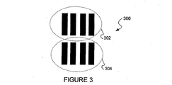
任意の適切な周期的ターゲットを用いてよい。図3は、本発明の一実施形態に従って、第1の層における第1の組の周期的な線構造302と、第2の層における第2の組の周期的な線構造304とを有する周期的なオーバレイターゲット300の一例を示す上面図である。もちろん、この特定の配列は、例示に過ぎず、本発明の範囲を限定するものではない。例えば、本明細書に記載された装置の実施形態と共に、正方形や点線など、他の構造の配列を用いてもよい。
Any suitable periodic target may be used. FIG. 3 illustrates a period having a first set of
結像光学系は、ターゲットの画像が2つの散乱平面波のみによって構築され、その画像が、正弦波画像になって、ターゲットと同じピッチを有するように、構成される。2つの出力ビームは、上述の式1または2の条件に従うように、任意の適切な機構によって生成される。これら2つのビームは、例えば、周期的なターゲットからの2つの回折次数によって生成されてよい。波長λを有する2つの出力ビームが、ピッチpを有する1つのターゲットから2θの角度分離で散乱することが好ましい。
The imaging optical system is configured so that the image of the target is constructed by only two scattered plane waves, and the image is a sine wave image and has the same pitch as the target. The two output beams are generated by any suitable mechanism so as to comply with the conditions of
オーバレイ(または、アライメント)が判定される時に、ターゲット形状の絶対位置は必要ない。しかしながら、第1の層上の構造の画像と、第2の層上の構造の画像との間の相対的な位置ずれは、オーバレイの判定にとって重要である。垂線に対する角度θと、波長λとを有する光線が、式1または2に従って選択されたピッチpを有する周期的なターゲットに入射する場合、ターゲットから散乱される出力ビームは、0次回折、−1次回折、+1次回折、−2次回折、+2次回折などと規定される複数の角度を有する。これら散乱された出力ビームは、回折格子の回折次数で呼ばれる。回折格子の回折次数の角度は、ターゲットのピッチと、入射ビームの波長および角度とによって決まる。したがって、一実施形態において、−1次回折または+1次回折が、照射光と同じ光路上に反射されるように、ターゲットのピッチを選択できる。
The absolute position of the target shape is not required when overlay (or alignment) is determined. However, the relative misalignment between the image of the structure on the first layer and the image of the structure on the second layer is important for overlay determination. When a ray having an angle θ with respect to a normal and a wavelength λ is incident on a periodic target having a pitch p selected according to
軸外照明を用いて、2つのビームで画像化を行うために、有効光源関数S(fx,fy)=δ(fx−υ,fy)が用いられる。ここで、fxおよびfyは、空間周波数の変数であり、υは、軸外周波数である。υが、υ=1/(2p)(pは、ターゲット回折格子のx方向のピッチ)のように選択される場合、0次回折次数は、方向(fx,fy)=(−1/(2p),0)に伝播し、−1次回折次数は、正確に反対の方向(fx,fy)=(−1/(2p)+1/p,0)=(1/(2p),0)に伝播する。 Using off-axis illumination, in order to perform the imaging in two beams, the effective light source function S (f x, f y) = δ (f x -υ, f y) is used. Here, f x and f y is a variable spatial frequency, upsilon is off-axis frequency. When υ is selected as υ = 1 / (2p) (p is the pitch in the x direction of the target diffraction grating), the zero order diffraction order is the direction (f x , f y ) = (− 1 / (2p), spread to 0), -1-order diffraction orders, exactly the opposite direction (f x, f y) = (- 1 / (2p) + 1 / p, 0) = (1 / (2p) , 0).
他の周期性を有するパターンについて、焦点に関する画像の対称性を保証するために、原点に関して、有効光源のバランスを取ることが可能であり、その結果として、以下の双極子構成となる。 For patterns with other periodicities, it is possible to balance the effective light source with respect to the origin to ensure image symmetry with respect to the focus, resulting in the following dipole configuration:
両方向で回折格子を画像化するために、以下のように、対角四極子構成を用いることが好ましい。 In order to image the diffraction grating in both directions, it is preferable to use a diagonal quadrupole configuration as follows.
以下の交差四極子構成を用いてもよく、これは、画像形成に寄与する光の総量に関して不利であり、DC背景光成分が加わるが、いくつかの他の利点を有しうる)。 The following crossed quadrupole configuration may be used, which is disadvantageous with respect to the total amount of light contributing to imaging and adds a DC background light component, but may have several other advantages).
結像光学系は、さらに、各入射ビームについて、−1次または1次(および0次)回折のみが、結像レンズによって捕捉されるように、構成される。υ=1/(2p)での有効光源について、「1次回折」の画像化(0次と、−1次または+1次のいずれかのみが、結像レンズによって捕捉される)の条件は、以下のピッチの回折格子に対して実現される。 The imaging optics is further configured such that for each incident beam, only -1st order or 1st order (and 0th order) diffraction is captured by the imaging lens. For an effective light source at υ = 1 / (2p), the conditions for “first order diffraction” imaging (only the 0th order and either the −1st order or the + 1st order are captured by the imaging lens) are: Realized for diffraction gratings with the following pitch
光学系によって分解されるように、ピッチは、さらに、式4を満たす必要がある。 In order to be resolved by the optical system, the pitch must further satisfy Equation 4.
したがって、式5により、「1次回折」の画像化のためのピッチ、λ、および、NAの間の以下の関係が与えられる。 Thus, Equation 5 gives the following relationship between pitch, λ, and NA for “first order diffraction” imaging.
式5は、双極子照明および対角四極子照明の構成に関連する。 Equation 5 relates to the configuration of dipole illumination and diagonal quadrupole illumination.
交差四極子照明の場合には、pに関して、より制限された条件が適用される。「1次回折」については、X回折格子からのY軸極の±1次の回折次数が、レンズによって集光されないことを保証する必要があるため、pは、式6を満たす必要がある。 In the case of crossed quadrupole illumination, more restrictive conditions apply for p. For “first-order diffraction”, it is necessary to ensure that the ± first-order diffraction orders of the Y-axis pole from the X diffraction grating are not collected by the lens, and therefore p needs to satisfy Expression 6.
図4は、本発明の一実施例に従って、2つの回折次数のみが捕捉される一般的な1次回折画像化システムを示す説明図である。図に示すように、入射ビーム402は、回折格子ターゲット404に向けられる。次いで、複数の回折次数が、ターゲット404から散乱される。
FIG. 4 is an illustration showing a typical first order diffraction imaging system in which only two diffraction orders are captured, according to one embodiment of the present invention. As shown, the
画像化システム(ここでは、レンズ410として図示されている)は、この例では、+1および+2の回折次数のみを捕捉するよう構成されている。これを実現するために、これら2つの回折次数のみを捕捉するように、結像レンズのサイズが決められ、または、開口絞りが調整されて、レンズが配置される。図に示すように、レンズ410の一部のみが示されているが、図示しない他の部分は、開口絞りを用いて遮蔽されている。
The imaging system (shown here as lens 410) is configured to capture only +1 and +2 diffraction orders in this example. To achieve this, the imaging lens is sized or the aperture stop is adjusted to capture the lens so that only these two diffraction orders are captured. As shown in the figure, only a part of the
結像レンズは、任意の2つの回折次数を捕捉するよう構成されてよい。図4に示すように、+1次403および+2次406は、結像レンズ410を通過するが、他の次数はすべて、かかる結像レンズ410への通過を阻まれる。実際には、2つの略平面波412aおよび412bが、結像レンズ410から出力される。これらの出力ビーム412aおよび412bは、非常に広い焦点深度にわたって、正弦波画像414を形成する。(簡単のため、この焦点範囲の中央の平面のみが図示されている)。すなわち、比較的広い範囲の位置に、センサ(図示せず)を配置することが可能であり、このセンサの位置範囲にわたって良好な焦点を実現しつつ、正弦波画像414を検出することができる。
The imaging lens may be configured to capture any two diffraction orders. As shown in FIG. 4, the +
図4Aは、本発明の別の実施形態に従って、レンズによって捕捉される2つの回折次数が、0次および−1次の回折次数である場合の1次回折画像化システムを示す説明図である。図に示すように、入射ビーム452は、回折格子ターゲット454に向けられる。次いで、複数の回折次数が、ターゲット454から散乱される。図に示すように、0次の回折次数453は、入射ビーム452の正反射である。−1次の回折次数456は、入射ビーム452と同じ光路を反対方向に進む。他の次数も、ターゲット454から散乱される。例えば、+1次の回折次数458も、ターゲットから散乱される。−2次および+2次の回折次数など、他の回折次数も、周期的なターゲット454から散乱されるが、図を簡単にするために、図示されていない。
FIG. 4A is an illustration showing a first order diffraction imaging system where the two diffraction orders captured by the lens are the 0th and −1st diffraction orders, according to another embodiment of the present invention. As shown, the
画像化システム(ここでは、レンズ460として図示されている)は、0次および−1次の回折次数のみを捕捉するよう、(上述の式2ないし5を用いて)構成される。これを実現するために、これら2つの回折次数のみが捕捉されるように、結像レンズのサイズすなわち開口数(NA)が調整される。 The imaging system (shown here as lens 460) is configured (using equations 2-5 above) to capture only the 0th and -1st diffraction orders. To achieve this, the size of the imaging lens, i.e. the numerical aperture (NA), is adjusted so that only these two diffraction orders are captured.
図4Aに示すように、0次453および−1次456は、結像レンズ460を通過するが、他の次数(例えば、+1次の回折次数458)はすべて、かかる結像レンズ460への通過を阻まれる。実際には、2つの略平面波462aおよび462bが、結像レンズ460から出力される。これらの出力ビーム462aおよび462bは、非常に広い焦点深度にわたって、正弦波画像464を形成する。(簡単のため、この焦点範囲の中央の平面のみが図示されている)。すなわち、比較的広い範囲の位置に、センサ(図示せず)を配置することが可能であり、このセンサの位置範囲にわたって良好な焦点を実現しつつ、正弦波画像を検出することができる。
As shown in FIG. 4A, the
電荷結合素子(CCD)またはCMOSなど、任意の適切なセンサを用いて、画像化された周期的なターゲットから正弦波画像を検出してよい。 Any suitable sensor, such as a charge coupled device (CCD) or CMOS, may be used to detect a sinusoidal image from the imaged periodic target.
本発明の実施形態は、いくつかの利点を提供する。例えば、本明細書に記載の画像化システムは、2つの隣接する周期的なターゲット、すなわち、第1の層の第1の周期的なターゲットと第2の層の第2の周期的なターゲットを画像化するオーバレイ測定に利用可能である。第1および第2の周期的なターゲットが、同じピッチを有し(例えば、図3の第1および第2のターゲット302および304)、レンズによって捕捉される2つの回折次数が、式2の条件を満たすような特定の分離角度および波長を有するように、入射ビームによって照射された場合には、第1および第2のターゲットは両方とも、0次および−1次の回折次数のビームのみによって画像化され、それらのビームは、同じ位置で結像レンズをサンプリングする。
Embodiments of the present invention provide several advantages. For example, the imaging system described herein includes two adjacent periodic targets: a first periodic target in a first layer and a second periodic target in a second layer. It can be used for overlay measurement to be imaged. The first and second periodic targets have the same pitch (eg, the first and
したがって、本発明の実施形態により、0次および−1次の回折次数が、両方のターゲットについて通過する位置が同じになるため、両方の層について画像化システムを通過する時に出力ビームに生じる収差が同じになるように規定される。換言すると、結像レンズは、第1の層のターゲットと第2の層のターゲットの両方について、同じ配置誤差を引き起こすため、2つの層の間のオーバレイ測定におけるツール起因シフト(TIS)がゼロになる。実際に、第1の層のターゲットと第2の層のターゲットとの間の配置誤差の差であるTISは、相殺される。例えば、結像光学系の収差が、第1の層について0次および−1次の回折次数の出力ビームによって形成される正弦波の位置を、右に2nmだけずらす場合に、これらの収差は、同様に、第2の層について0次および−1次の回折次数の出力ビームによって形成される正弦波を、右に2nmだけずらす。 Thus, according to an embodiment of the present invention, the 0th and −1st order diffraction orders have the same position to pass for both targets, so the aberrations that occur in the output beam when passing through the imaging system for both layers. It is prescribed to be the same. In other words, the imaging lens causes the same placement error for both the first layer target and the second layer target, so that the tool-induced shift (TIS) in the overlay measurement between the two layers is zero. Become. In fact, the TIS, which is the difference in placement error between the first layer target and the second layer target, is offset. For example, when the aberration of the imaging optical system shifts the position of the sine wave formed by the output beam of the 0th order and −1st order diffraction orders for the first layer to the right by 2 nm, these aberrations are: Similarly, the sine wave formed by the 0th and −1st order diffraction order output beams for the second layer is shifted to the right by 2 nm.
つまり、第1の層のターゲットと第2の層のターゲットとの間の相対的な位置ずれだけが重要であり、2つのターゲットのいずれの絶対的な位置も重要ではないことから、配置誤差は、オーバレイの判定に影響を与えない。第1および第2の層のターゲットからの2つの画像の間の任意のずれは、オーバレイ誤差のみに起因するものである。 That is, only the relative misalignment between the first layer target and the second layer target is important, and the absolute position of either of the two targets is not important, so the placement error is Does not affect the overlay determination. Any deviation between the two images from the first and second layer targets is due to overlay errors only.
オーバレイ誤差は、第1および第2の層のターゲットからの画像がずれているか否か、および、どの程度ずれているのか、を解析することにより、任意の適切な方法で判定されてよい。一実施形態では、第1の層の画像の対称中心(COS)が決定され、第2の層の画像のCOSが決定される。次いで、第1のCOSと第2のCOSとの間の差が、オーバレイ誤差として定義されてよい。正弦波画像の位相は、ターゲットの位相に対応するため、第1の層の構造の正弦波の位相を、第2の層の構造の正弦波の位相と比較することができる。次いで、位相差を、空間的なずれに変換して、オーバレイ誤差として定義することができる。 The overlay error may be determined in any suitable manner by analyzing whether and how much the images from the first and second layer targets are misaligned. In one embodiment, the center of symmetry (COS) of the first layer image is determined and the COS of the second layer image is determined. The difference between the first COS and the second COS may then be defined as the overlay error. Since the phase of the sine wave image corresponds to the phase of the target, the phase of the sine wave of the first layer structure can be compared with the phase of the sine wave of the second layer structure. The phase difference can then be converted to a spatial shift and defined as overlay error.
理論的に、1つの入射ビームを用いて、上述の式の条件を満足する2つの出力ビーム、すなわち、0次および1次の回折次数のビームを生成することができる。例えば、図4Aに示したように、1つの入射ビーム452により、0次の回折次数の出力ビーム453と、−1次の回折次数の出力ビーム456とが生成される。次いで、これら2つの出力ビームは、結像レンズ460を通過し、干渉することにより正弦波画像464を形成する2つの出力ビーム462aおよび462bになる。
Theoretically, a single incident beam can be used to generate two output beams that satisfy the conditions of the above equation, ie, 0th and 1st diffraction order beams. For example, as shown in FIG. 4A, one
別の実施形態では、2つの入射ビームを用いて、より多くの光をターゲット上に生成し、より明るい画像を生成する。図4Bは、2つの入射ビームを用いた場合の1次の回折次数の画像化システムを示す説明図である。この構成は、双極子照明と呼ばれる。図に示すように、2つの入射ビーム472aおよび472bが、ターゲット474に向けられる。次いで、複数の回折次数が、ターゲット474から散乱される。図に示すように、0次の回折次数473aおよび473bは、それぞれ、入射ビーム472aおよび472bの正反射である。同様に、−1次の回折次数476aおよび+1次の回折次数476bは、それぞれ、0次の回折次数のビーム474bおよび474aと同じ光路をたどる。他の回折次数も、周期的なターゲット474から散乱されるが、図を簡略化するために、図示されていない。0次および−1次の回折次数473aおよび476aによる正弦波画像484は、0次および+1次の回折次数473bおよび476bによる正弦波画像484を強化するように重なる。その結果、より明るい正弦波画像484が形成される。
In another embodiment, two incident beams are used to generate more light on the target and a brighter image. FIG. 4B is an explanatory diagram showing a first-order diffraction order imaging system using two incident beams. This configuration is called dipole illumination. As shown, two
本発明の実施形態は、さらに、プロセスのロバスト性を改善する利点を有する。従来の画像化では、ウエハにおける複数の場所に位置する同じターゲットを測定した時に、画像が、ウエハにわたって変動することが観察されていた。画像の変動は、ウエハにわたるプロセス変動によるものである。各場所は、例えば、異なるスペクトル強度分布および角度強度分布で反射するなど、やや異なる特性を有する。しかしながら、周期的なターゲットは、各波長について特定の角度に回折次数を維持し、2つのビームのみの画像化を可能とすることにより、プロセスではなく、ターゲットのピッチのみに依存するピッチで、正弦波画像が形成される。 Embodiments of the present invention further have the advantage of improving process robustness. In conventional imaging, it has been observed that the image varies across the wafer when measuring the same target located at multiple locations on the wafer. Image variations are due to process variations across the wafer. Each location has slightly different characteristics, for example reflecting with different spectral intensity distribution and angular intensity distribution. However, a periodic target maintains a diffractive order at a specific angle for each wavelength and allows for imaging of only two beams, thereby making the sine at a pitch that depends only on the pitch of the target, not the process. A wave image is formed.
また、オーバレイ測定では、これにより、TISの発生の可能性が低くなる。TISの変動も、ウエハにわたるプロセス変動によるものである。1次の回折次数の画像化については、光学収差によるTISは排除されるため、TISの発生可能性は低減される。したがって、TISおよびオーバレイ測定は、プロセス変動からの影響を受けにくくなる。 Also, in overlay measurements, this reduces the possibility of TIS occurrence. TIS variations are also due to process variations across the wafer. For first-order diffraction order imaging, TIS due to optical aberrations is eliminated, reducing the likelihood of TIS generation. Thus, TIS and overlay measurements are less susceptible to process variations.
また、本発明の実施形態によると、画像のコントラストが高くなる。明視野光源で画像化された単独の線の場合には、照明が、複数の角度で生成されることから、複数の回折次数が、複数の角度で生成される。実際には、複数の回折次数が、異なる照明角度の各々について生成される。出力光線の一部は、結像光学系によって捕捉された1つの強く回折された次数を有するのみであり、この単一の次数の光線は、干渉すべき対応するコヒーレントな光線を持たないため、画像の形成に寄与することはない。したがって、この単一の次数の光線は、全体的なDC背景に寄与するだけである。この影響により、コントラストの質が低くなる。 In addition, according to the embodiment of the present invention, the contrast of the image is increased. In the case of a single line imaged with a bright field light source, illumination is generated at a plurality of angles, so that a plurality of diffraction orders are generated at a plurality of angles. In practice, multiple diffraction orders are generated for each different illumination angle. Since some of the output rays have only one strongly diffracted order captured by the imaging optics, this single order ray has no corresponding coherent ray to interfere with, It does not contribute to image formation. Thus, this single order ray only contributes to the overall DC background. This effect reduces the quality of the contrast.
本発明の実施形態では、照明は、特定の角度にのみ方向付けられるため、その結果、結像レンズによって捕捉されて互いに干渉することで正弦波画像を形成する正確に対応した回折次数の対が生成される。すなわち、結像レンズによって捕捉されるすべての光線が、画像化情報に利用される。図4Bの例では、コヒーレントであるために、互いに干渉して正弦波画像を形成する0次および1次の回折次数の2つの対が示されている。具体的には、0次の回折次数のビーム473aおよび−1次の回折次数のビーム476aが、第1の正弦波画像を形成し、0次の回折次数のビーム473bおよび+1次の回折次数のビーム476bが、重なり合うことで第1の正弦波画像を強化する第2の正弦波画像を形成する。本発明の実施形態で画像化される出力ビームのすべてが、画像に寄与するため、DC背景ノイズが少なくなる。したがって、従来の他の型の画像化システムよりも、コントラストが改善される。
In an embodiment of the present invention, the illumination is directed only at a certain angle, so that there are exactly corresponding pairs of diffraction orders that are captured by the imaging lens and interfere with each other to form a sinusoidal image. Generated. That is, all light rays captured by the imaging lens are used for imaging information. In the example of FIG. 4B, two pairs of zeroth and first order diffraction orders are shown that coherently interfere with each other to form a sinusoidal image. Specifically, the 0th
上述の実施形態では、1つの方向(例えば、x方向)に周期的な構造を有するターゲットに対して、2つの入射ビームが向けられている。この実施形態は、双極子照明系と呼ばれる。あるいは、yおよびx方向の両方に周期的な構造を有するターゲットを画像化するために、四極子照明系を用いてもよい。もちろん、x方向ターゲットおよびy方向ターゲットの両方に対して、双極子系を用いてもよく、その場合には、xまたはy方向ターゲットの一方を、2つのビームを用いて第1の方向で画像化した後に、xまたはy方向ターゲットの他方を、第2の方向で画像化できるように、双極子照明系に対してウエハを回転させる。別の実施形態では、交差四極子照明を用いて、x方向で2つのビームを提供すると共に、y方向で2つのビームを提供してもよい。さらに別の実施形態では、x方向に2つの入射光を提供してy方向に2つの入射光を提供する構成と対照的に、対角四極子照明を用いて、xおよびyの両方向にそれぞれ寄与する4つのビームを提供してもよい。これらの異なる極構成について、さらに、数学的に説明する。 In the above-described embodiment, two incident beams are directed to a target having a periodic structure in one direction (for example, the x direction). This embodiment is called a dipole illumination system. Alternatively, a quadrupole illumination system may be used to image a target having a periodic structure in both the y and x directions. Of course, a dipole system may be used for both the x and y direction targets, in which case one of the x or y direction targets is imaged in the first direction using two beams. After rotation, the wafer is rotated relative to the dipole illumination system so that the other of the x or y direction targets can be imaged in the second direction. In another embodiment, crossed quadrupole illumination may be used to provide two beams in the x direction and two beams in the y direction. In yet another embodiment, in contrast to a configuration that provides two incident lights in the x direction and two incident lights in the y direction, diagonal quadrupole illumination is used, respectively, in both the x and y directions. Four contributing beams may be provided. These different pole configurations are further described mathematically.
図5Aは、一実施形態に従って、双極子照明系500を用いたケーラー照明系を示す側面図である。図に示すように、照明系500は、すべての角度に光513を放射する光源512を備える。任意の適切な数の光源を用いてよい。光源からの光513は、開口面(開口絞り)508に向けられる。開口面508は、1または複数の開口部を備えることで、すべての角度に放射して光束(2つの光束509aおよび509bなど)を形成する1または複数の点光源を形成する。あるいは、発光ダイオード(LED)など、すべての角度に放射する2つの実際の点光源を、開口面508に配置して、2つの光束509aおよび509bを形成してもよい。次に、これら2つの光束509aおよび509bは、2つの光束509aおよび509bを、特定の角度で周期的なターゲット502に向けられる第1のビーム504aおよび第2のビーム504bの形態で収束させるよう構成された集光レンズ510を通過する。
FIG. 5A is a side view illustrating a Koehler illumination system using a
第1および第2のビーム504aおよび504bは、x軸に沿ったターゲットのピッチpxと、用いられている特定の波長とに、ほぼ適合された2θxの分離を有する。2つの入射ビーム504aおよび504bは、1つの方向におけるターゲットの画像化に利用される。例えば、入射ビーム504は、x方向の構造を画像化するために用いられるが、それらは、y方向の構造を画像化するために用いられてもよい。図5Bは、図5Aの2つの入射ビーム504aおよび504bに関して、照明系500の開口絞り508を示す上面図である。図に示すように、ビーム504aおよび504bは、開口絞り508から放射されて、2つの方向からターゲット502に向かう。
The first and
図5Cは、別の照明系の実施形態を示す説明図である。図に示すように、入射ビーム520が、DOE(回折光学素子)521によって複数のビーム522に分割され、その結果、複数のビームが、所望の位置において開口面524に当たる。次いで、各ビーム522は、すべての方向に光束を放射するように、拡散器526によって角度を拡散される。次に、これらの光束は、2つの光束を収束させて特定の角度でターゲットに当てるよう構成された集光レンズ510(図示せず)を通過する。
FIG. 5C is an explanatory diagram showing another embodiment of an illumination system. As shown in the figure, the
x方向およびy方向の両方に構造を有するターゲットについては、x方向の構造用の2つのビームと、y方向の構造用の2つのビームとを生成するように、照明系を構成してもよい。図5Dは、この交差四極子構成のための照明系の開口絞りを示す上面図である。図に示すように、開口部556aからの第1のビームと、開口部556bからの第2のビームとが、y方向のターゲット構造を画像化するために、周期的なターゲットに向けられる。これらのy方向のビーム556は、y軸に沿ったターゲットのピッチpyと、用いられている特定の波長とに適合された2θyの分離をy軸に沿って有する。同様に、開口部554aからの第1のビームと、開口部554bからの第2のビームとが、x方向のターゲット構造を画像化するために、同じターゲットに向けられる。これらのビーム554は、x軸に沿ったターゲットのピッチpxと、用いられている特定の波長とに適合された2θxの分離をx軸に沿って有する。 For targets having structures in both the x and y directions, the illumination system may be configured to generate two beams for structures in the x direction and two beams for structures in the y direction. . FIG. 5D is a top view showing the aperture stop of the illumination system for this crossed quadrupole configuration. As shown, the first beam from opening 556a and the second beam from opening 556b are directed to a periodic target to image the target structure in the y direction. Beam 556 of the y-direction, has along the pitch p y of the target along the y-axis, the separation of a specific wavelength and the adapted 2 [Theta] y used in the y-axis. Similarly, the first beam from opening 554a and the second beam from opening 554b are directed to the same target to image the target structure in the x direction. These beams 554 have a 2θ x separation along the x-axis that is adapted to the target pitch p x along the x-axis and the particular wavelength being used.
図5Eは、この対角四極子構成のための照明系の開口絞りを示す上面図である。この構成では、開口部574aないし574dからのビームはすべて、x方向の構造およびy方向の構造の両方の画像形成に寄与する。
FIG. 5E is a top view showing the aperture stop of the illumination system for this diagonal quadrupole configuration. In this configuration, all the beams from the
図6は、本発明の一実施形態に従って、ターゲットの取得、もしくは、オーバレイまたはアライメントの判定を行うための1次回折画像化用の光学画像化システムを示す説明図である。明確にするために、照明光路は、そのシステムが透過光学系であるかのように図示されている。ほとんどの実施形態では、画像化システムは反射光学系であり、その照明光路も、上から下に向かって対物レンズを通過する。図に示すように、システム600は、特定のピッチpの構造を有する周期的なターゲットに、少なくとも1つのビームを向けるためのビーム発生器602と、例えば、図4Aを参照して上述したように、ターゲット612からの第1および第2の出力ビームのみを導くための結像レンズ系610とを備える。少なくとも1つの入射ビームは、波長値λと、周期的なターゲットに向かってターゲットの面に垂直な軸からの角度θとを有する。少なくとも1つの入射ビームの角度θおよび波長値λと、周期的なターゲットのピッチpとは、式2の条件をほぼ満たすように選択される。システムは、さらに、第1および第2の出力ビームを受光して第1および第2の出力ビームに基づく画像を生成するためのセンサ612を備える。なお、その画像は、正弦波画像である。システムyは、さらに、(i)特定のピッチpを有する周期的な1つのターゲットまたは1組の複数ターゲットに対して、少なくとも1つの入射ビームを向けるように、ビーム発生器を制御することで、センサが、1または複数のターゲットの画像を生成できるようにするため、および、(ii)その画像を解析するための制御部を備える。ターゲット取得に用いる場合には、画像解析は、画像が実際に取得ターゲットであるか否かを判定することを含む。オーバレイ測定に用いる場合には、画像解析は、第1および第2の層からの第1および第2のターゲットが、オーバレイまたはアライメント誤差を有するか否かを判定することを含む。
FIG. 6 is an illustration showing an optical imaging system for first order diffraction imaging for target acquisition or overlay or alignment determination according to one embodiment of the present invention. For clarity, the illumination light path is illustrated as if the system is a transmission optics. In most embodiments, the imaging system is a reflective optical system whose illumination path also passes through the objective lens from top to bottom. As shown, the
本発明の一実施形態では、ビーム発生器は、光源604と集光レンズ606とを用いて実現される。光源は、集光レンズに向けられる少なくとも1つの軸外照明の光束を生成するため、もしくは、ピッチpを有する周期的なターゲットに向けられる少なくとも1つの軸外照明のビームを生成するための回折光学素子(DOE)など、任意の適切な素子によって実現されてよい。DOEで照明ビームを実現することの利点は、式1または2の条件に対して、スペクトル的に「自己整合」するように、DOEを設計できる点である。すなわち、各波長が、異なる入射角θに方向付けられるスペクトルの広い入射ビームを、ターゲットに向けるために、1つのDOEを用いることで、入射ビームの全波長について式1または2が同時に満たされるようにすることができる。DOEは、複数の照射ビームを生成するために用いられてもよい。回折ビーム増倍素子を用いて、ビームを、出力および伝播角度以外は元のビームの特性をそれぞれ有するいくつかのビームに分割してもよい。
In one embodiment of the invention, the beam generator is implemented using a
理解を深めるために、上述の発明について、ある程度詳しく説明したが、添付の特許請求の範囲内で、ある程度の変更や変形を行ってもよいことは明らかである。したがって、上述の実施形態は、例示的なものであって、限定的なものではないとみなされ、本発明は、本明細書に示した詳細事項に限定されず、添付の特許請求の範囲およびその等価物の範囲によって規定される。 For better understanding, the above invention has been described in some detail, but it will be apparent that some changes and modifications may be made within the scope of the appended claims. Accordingly, the above-described embodiments are considered to be illustrative and not restrictive, and the invention is not limited to the details set forth herein, but the appended claims and Defined by the scope of its equivalents.
Claims (30)
波長λを有する少なくとも1つの入射ビームを、特定のピッチpを持つ構造を有する周期的なターゲットに向けるためのビーム発生器であって、前記少なくとも1つの入射ビームに応じて、前記周期的なターゲットから複数の出力ビームが散乱される、ビーム発生器と、
前記ターゲットからの第1および第2の出力ビームのみを通すための結像レンズ系であって、前記第1および第2の出力ビームに、ほぼ純粋な正弦波画像を形成させるように、前記第1の出力ビームと前記第2の出力ビームとの間の角度分離と、λと、前記ピッチとが選択されるよう適合された、結像レンズ系と、
前記正弦波画像を画像化するためのセンサと、
特定のピッチpをそれぞれ有する第1および第2の周期的なターゲットに前記少なくとも1つの入射ビームを向けるように、前記ビーム発生器を制御することで、前記センサが前記第1のターゲットの第1の正弦波画像と前記第2のターゲットの第2の正弦波画像とを検出するようにすると共に、前記第1および第2の正弦波画像を解析して、前記第1および第2のターゲットの間のオーバレイまたはアライメント誤差を判定するための制御部と、を備え、
前記第1のターゲットは、第1の層の上に配置され、前記第2のターゲットは、第2の層の上に配置され、前記制御部は、前記第1の正弦波画像と前記第2の正弦波画像との間のずれを前記オーバレイ誤差として定義することにより、前記第1および第2のターゲットの間のオーバレイ誤差を判定するよう構成されている、システム。A system for imaging a plurality of targets in a tool for inspecting or measuring semiconductors, comprising:
A beam generator for directing at least one incident beam having a wavelength λ to a periodic target having a structure with a specific pitch p, the periodic target in response to the at least one incident beam A beam generator from which a plurality of output beams are scattered,
An imaging lens system for passing only the first and second output beams from the target, wherein the first and second output beams form a substantially pure sinusoidal image. An imaging lens system adapted to select an angular separation between one output beam and the second output beam, λ, and the pitch;
A sensor for imaging the sine wave image;
Controlling the beam generator to direct the at least one incident beam to first and second periodic targets, each having a particular pitch p, causes the sensor to have a first first target of the first target. And a second sine wave image of the second target are detected , and the first and second sine wave images are analyzed to detect the first and second targets. A controller for determining an overlay or alignment error between ,
The first target is disposed on a first layer, the second target is disposed on a second layer, and the control unit is configured to transmit the first sine wave image and the second layer. The system is configured to determine an overlay error between the first and second targets by defining a deviation between the first and second targets as the overlay error .
前記第1および第2の入射ビームは、条件p=λ/(2sinθ)(λは前記波長であり、pは前記周期的なターゲットのピッチ)をほぼ満たすように選択された2θの角度分離を有し、
前記第1および第2の出力ビームは、それぞれが、前記1次の回折次数と0次の回折次数とを含む、システム。5. The system of claim 4 , wherein the beam generator is adapted to direct first and second incident beams in a dipole configuration to the first and second targets;
The first and second incident beams have an angle separation of 2θ selected to substantially satisfy the condition p = λ / (2 sin θ), where λ is the wavelength and p is the pitch of the periodic target. Have
It said first and second output beams, each comprising a said first diffraction orders and 0 diffraction order, system.
波長λを有する少なくとも1つの入射ビームを、特定のピッチpを持つ構造を有する周期的なターゲットに向けるためのビーム発生器であって、前記少なくとも1つの入射ビームに応じて、前記周期的なターゲットから複数の出力ビームが散乱される、ビーム発生器と、 A beam generator for directing at least one incident beam having a wavelength λ to a periodic target having a structure with a specific pitch p, the periodic target in response to the at least one incident beam A beam generator from which a plurality of output beams are scattered,
前記ターゲットからの第1および第2の出力ビームのみを通すための結像レンズ系であって、前記第1および第2の出力ビームに、複数の連続的な像平面にわたってほぼ純粋な正弦波画像を形成させるように、前記第1の出力ビームと前記第2の出力ビームとの間の角度分離と、λと、前記ピッチとが選択されるよう適合された、結像レンズ系と、 An imaging lens system for passing only the first and second output beams from the target, wherein the first and second output beams are substantially pure sinusoidal images over a plurality of continuous image planes. An imaging lens system adapted to select an angular separation between the first output beam and the second output beam, λ, and the pitch so as to form:
前記正弦波画像を画像化するためのセンサと、 A sensor for imaging the sine wave image;
特定のピッチpを有するターゲットに前記少なくとも1つの入射ビームを向けるように、前記ビーム発生器を制御することで、前記センサがの正弦波画像を検出するようにすると共に、前記ターゲットの設計のピッチと前記検出された正弦波画像のピッチとを比較することにより、ターゲット取得が成功したか否かを判定するよう構成された制御部と、を備える、システム。 Controlling the beam generator to direct the at least one incident beam onto a target having a specific pitch p, so that the sensor detects a sinusoidal image of the target and the pitch of the target design And a controller configured to determine whether the target acquisition was successful by comparing the detected pitch of the sine wave image.
前記ビーム発生器は、第1および第2の入射ビームと、第3および第4の入射ビームとを、交差四極子構成で、第1および第2の周期的なターゲットに向けるよう適合されており、
前記第1および第2の入射ビームは、条件px=λ/(2sinθx)(λは前記波長である)をほぼ満たすように選択された前記x方向に沿った2θxの角度分離を有し、
前記第3および第4の入射ビームは、条件py=λ/(2sinθ y )をほぼ満たすように選択された前記y方向に沿った2θyの角度分離を有する、システム。A system according to claim 1, wherein the specific pitch p, the pitch p x about the structure of the periodic targets arranged along the x direction, the periodic arranged along the y-direction and a pitch p y about the structure of specific targets,
The beam generator is adapted to direct the first and second incident beams and the third and fourth incident beams in a crossed quadrupole configuration to the first and second periodic targets. ,
Wherein the first and second incident beam, the angular separation conditions p x = λ / (2sinθ x ) (λ is the wavelength Ru der) 2 [Theta] x along the selected the x-direction so as to satisfy substantially the Have
The system wherein the third and fourth incident beams have an angular separation of 2θ y along the y direction selected to substantially satisfy the condition p y = λ / (2 sin θ y ) .
前記ビーム発生器は、第1、第2、第3、および、第4の入射ビームを、対角四極子構成で、周期的なターゲットに向けるよう適合されており、
前記第1、第2、第3、および、第4の入射ビームは、x軸上に投射される場合には、条件px=λ/(2sinθx)(λは前記波長である)をほぼ満たすように選択された前記x方向に沿った2θxの角度分離を有するよう構成され、
y軸上に投射される場合には、条件py=λ/(2sinθy )をほぼ満たすように選択された前記y方向に沿った2θyの角度分離を有するよう構成されている、システム。A system according to claim 1, wherein the specific pitch p, the pitch p x about the structure of the periodic targets arranged along the x direction, the periodic arranged along the y-direction and a pitch p y about the structure of specific targets,
The beam generator is adapted to direct the first, second, third and fourth incident beams in a diagonal quadrupole configuration to a periodic target;
Said first, second, third, and the incident beam of the fourth, when projected onto the x-axis, the condition p x = λ / (2sinθ x ) a (lambda is Ru said wavelength der) Configured to have an angular separation of 2θ x along the x direction selected to approximately satisfy,
A system configured to have an angle separation of 2θ y along the y direction selected to substantially satisfy the condition p y = λ / (2 sin θ y ) when projected on the y-axis.
波長λを有する少なくとも1つの入射ビームを、特定のピッチpを持つ構造を有する第1および第2の周期的なターゲットに向ける工程であって、前記少なくとも1つの入射ビームに応じて、前記第1および第2の周期的なターゲットの各々から複数の出力ビームが散乱される、工程と、
前記第1および第2のターゲットの各々からの第1および第2の出力ビームのみを通す工程であって、画像化システムは、前記第1および第2のターゲットからの前記第1および第2の出力ビームに、ほぼ純粋な第1および第2の正弦波画像をそれぞれ形成させるように、前記第1の出力ビームと前記第2の出力ビームとの間の角度分離と、λと、前記ピッチとが選択されるよう適合されている、工程と、
前記第1のターゲットの前記第1の正弦波画像と、前記第2のターゲットの前記第2の正弦波画像とを検出する工程と、
前記第1および第2の正弦波画像を解析して、前記第1および第2のターゲットの間のオーバレイまたはアライメント誤差を判定する工程と、を備え、
前記第1のターゲットは、第1の層の上に配置され、前記第2のターゲットは、第2の層の上に配置され、前記第1および第2のターゲットの間のオーバレイ誤差は、前記第1の正弦波画像と前記第2の正弦波画像との間のずれを前記オーバレイ誤差として定義することにより判定される、方法。A method for imaging an overlay or alignment semiconductor target comprising:
Directing at least one incident beam having a wavelength λ to first and second periodic targets having a structure with a specific pitch p, wherein the first beam depends on the at least one incident beam; And a plurality of output beams are scattered from each of the second periodic targets;
Passing only the first and second output beams from each of the first and second targets, wherein the imaging system includes the first and second targets from the first and second targets. An angular separation between the first output beam and the second output beam, λ, and the pitch so that the output beam forms substantially pure first and second sinusoidal images, respectively. A process adapted to be selected, and
Detecting the first sine wave image of the first target and the second sine wave image of the second target;
By analyzing the first and second sine wave image, and a step of determining the overlay or alignment error between said first and second targets,
The first target is disposed on a first layer, the second target is disposed on a second layer, and an overlay error between the first and second targets is A method wherein the deviation between a first sine wave image and the second sine wave image is determined by defining as the overlay error .
前記第1および第2の入射ビームは、条件p=λ/(2sinθ)(λは前記波長であり、pは前記周期的なターゲットのピッチ)をほぼ満たすように選択された2θの角度分離を有し、
前記第1および第2の出力ビームは、それぞれが、前記1次の回折次数と0次の回折次数とを含む、方法。The method of claim 19 , further comprising directing the first and second incident beams in a dipole configuration to the first and second targets,
The first and second incident beams have an angle separation of 2θ selected to substantially satisfy the condition p = λ / (2 sin θ), where λ is the wavelength and p is the pitch of the periodic target. Have
It said first and second output beams, each comprising a said first diffraction orders and 0 diffraction order, method.
前記方法は、さらに、
第1、第2、第3、および、第4の入射ビームを、交差四極子構成で、周期的なターゲットに向ける工程を備え、
前記第1および第2の入射ビームは、条件px=λ/(2sinθx)(λは前記波長である)をほぼ満たすように選択された前記x方向に沿った2θxの角度分離を有し、
前記第3および第4の入射ビームは、条件py=λ/(2sinθy )をほぼ満たすように選択された2θyの角度分離を有する、方法The method according to claim 17, wherein the specific pitch p, the pitch p x about the structure of the periodic targets arranged along the x direction, the periodic arranged along the y-direction and a pitch p y about the structure of specific targets,
The method further comprises:
Directing the first, second, third, and fourth incident beams in a crossed quadrupole configuration to a periodic target;
Wherein the first and second incident beam, the angular separation conditions p x = λ / (2sinθ x ) (λ is the wavelength Ru der) 2 [Theta] x along the selected the x-direction so as to satisfy substantially the Have
The third and fourth incident beams have a 2θ y angular separation selected to substantially satisfy the condition p y = λ / (2 sin θ y ).
検出器が、前記第1のターゲットの第1の正弦波画像と、前記第2のターゲットの第2の正弦波画像とを検出するように、前記第1および第2の入射ビームを、前記第1および第2の周期的なターゲットに向ける工程と、
前記第1および第2の正弦波画像を解析して、前記第1および第2のターゲットが、前記x方向のオーバレイまたはアライメント誤差を有するか否かを判定する工程と、
前記検出器が、第3のターゲットの第3の正弦波画像と、第4のターゲットの第4の正弦波画像とを検出するように、前記第3および第4の入射ビームを、第3および第4の周期的なターゲットに向ける工程と、
前記第3および第4の正弦波画像を解析して、前記第3および第4のターゲットが、前記y方向のオーバレイまたはアライメント誤差を有するか否かを判定する工程と、を備える、方法。28. The method of claim 27 , further comprising:
The first and second incident beams are the first and second incident beams such that a detector detects a first sine wave image of the first target and a second sine wave image of the second target. Directing to the first and second periodic targets;
Analyzing the first and second sinusoidal images to determine whether the first and second targets have an overlay or alignment error in the x direction;
The third and fourth incident beams are third and fourth so that the detector detects a third sine wave image of a third target and a fourth sine wave image of a fourth target. Directing to a fourth periodic target;
Analyzing the third and fourth sine wave images to determine whether the third and fourth targets have an overlay or alignment error in the y direction.
前記方法は、さらに、
第1、第2、第3、および、第4の入射ビームを、対角四極子構成で、周期的なターゲットに向ける工程を備え、
前記第1、第2、第3、および、第4の入射ビームは、x軸上に投射される場合には、条件px=λ/(2sinθx)(λは前記波長である)をほぼ満たすように選択された前記x方向に沿った2θxの角度分離を有するよう構成され、
y軸上に投射される場合には、条件py=λ/(2sinθy )をほぼ満たすように選択された前記y方向に沿った2θyの角度分離を有するよう構成される、方法。The method according to claim 17, wherein the specific pitch p, the pitch p x about the structure of the periodic targets arranged along the x direction, the periodic arranged along the y-direction and a pitch p y about the structure of specific targets,
The method further comprises:
Directing the first, second, third, and fourth incident beams in a diagonal quadrupole configuration to a periodic target;
Said first, second, third, and the incident beam of the fourth, when projected onto the x-axis, the condition p x = λ / (2sinθ x ) a (lambda is Ru said wavelength der) Configured to have an angular separation of 2θ x along the x direction selected to approximately satisfy,
A method configured to have an angular separation of 2θ y along the y direction selected to substantially satisfy the condition p y = λ / (2 sin θ y ) when projected on the y-axis.
検出器が、前記第1のターゲットの第1の正弦波画像と、前記第2のターゲットの第2の正弦波画像とを検出するように、前記第1、第2、第3、および、第4の入射ビームを、前記第1、第2、第3、および、第4の周期的なターゲットに向ける工程と、
前記第1および第2の正弦波画像を解析して、前記第1および第2のターゲットが、前記x方向のオーバレイまたはアライメント誤差を有するか否かを判定する工程と、
前記第3および第4の正弦波画像を解析して、前記第3および第4のターゲットが、前記y方向のオーバレイまたはアライメント誤差を有するか否かを判定する工程と、を備える、方法。30. The method of claim 29 , further comprising:
The first, second, third, and second so that a detector detects a first sine wave image of the first target and a second sine wave image of the second target. Directing four incident beams to the first, second, third, and fourth periodic targets;
Analyzing the first and second sinusoidal images to determine whether the first and second targets have an overlay or alignment error in the x direction;
Analyzing the third and fourth sine wave images to determine whether the third and fourth targets have an overlay or alignment error in the y direction.
Applications Claiming Priority (5)
| Application Number | Priority Date | Filing Date | Title |
|---|---|---|---|
| US65805605P | 2005-03-01 | 2005-03-01 | |
| US60/658,056 | 2005-03-01 | ||
| US72591805P | 2005-10-11 | 2005-10-11 | |
| US60/725,918 | 2005-10-11 | ||
| PCT/US2006/007195 WO2006094021A2 (en) | 2005-03-01 | 2006-02-28 | Target acquisition and overlay metrology based on imaging by two diffracted orders |
Publications (3)
| Publication Number | Publication Date |
|---|---|
| JP2008532320A JP2008532320A (en) | 2008-08-14 |
| JP2008532320A5 JP2008532320A5 (en) | 2009-03-19 |
| JP4994248B2 true JP4994248B2 (en) | 2012-08-08 |
Family
ID=36941762
Family Applications (1)
| Application Number | Title | Priority Date | Filing Date |
|---|---|---|---|
| JP2007558164A Active JP4994248B2 (en) | 2005-03-01 | 2006-02-28 | Target acquisition and overlay measurement based on imaging with two diffraction orders |
Country Status (3)
| Country | Link |
|---|---|
| US (1) | US7528953B2 (en) |
| JP (1) | JP4994248B2 (en) |
| WO (1) | WO2006094021A2 (en) |
Families Citing this family (25)
| Publication number | Priority date | Publication date | Assignee | Title |
|---|---|---|---|---|
| US20080273027A1 (en) * | 2004-05-12 | 2008-11-06 | Eric Feremans | Methods and Devices for Generating and Viewing a Planar Image Which Is Perceived as Three Dimensional |
| US7573584B2 (en) * | 2006-09-25 | 2009-08-11 | Asml Netherlands B.V. | Method and apparatus for angular-resolved spectroscopic lithography characterization |
| US7772710B2 (en) * | 2006-11-01 | 2010-08-10 | Sematech, Inc. | Zero-order overlay targets |
| TWI347428B (en) * | 2007-11-02 | 2011-08-21 | Ind Tech Res Inst | Overlay alignment structure and method for overlay metrology using the same |
| NL1036245A1 (en) | 2007-12-17 | 2009-06-18 | Asml Netherlands Bv | Diffraction based overlay metrology tool and method or diffraction based overlay metrology. |
| NL1036618A1 (en) * | 2008-03-24 | 2009-09-25 | Asml Netherlands Bv | Encoder-type measurement system, lithograpic apparatus and method for detecting an error on a grid or grating or an encoder-type measurement system. |
| US9223227B2 (en) * | 2011-02-11 | 2015-12-29 | Asml Netherlands B.V. | Inspection apparatus and method, lithographic apparatus, lithographic processing cell and device manufacturing method |
| NL2009001A (en) * | 2011-07-08 | 2013-01-09 | Asml Netherlands Bv | Methods and patterning devices for measuring phase aberration. |
| KR101761735B1 (en) | 2012-03-27 | 2017-07-26 | 에이에스엠엘 네델란즈 비.브이. | Metrology method and apparatus, lithographic system and device manufacturing method |
| JP5873212B2 (en) * | 2012-04-12 | 2016-03-01 | エーエスエムエル ネザーランズ ビー.ブイ. | POSITION MEASURING METHOD, POSITION MEASURING DEVICE, LITHOGRAPHIC APPARATUS, DEVICE MANUFACTURING METHOD, AND OPTICAL ELEMENT |
| JP6353831B2 (en) | 2012-06-26 | 2018-07-04 | ケーエルエー−テンカー コーポレイション | Algorithmic removal from scanning and diffraction optical measurements in angle-resolved reflectometry |
| US9243886B1 (en) | 2012-06-26 | 2016-01-26 | Kla-Tencor Corporation | Optical metrology of periodic targets in presence of multiple diffraction orders |
| US9778025B2 (en) | 2012-08-16 | 2017-10-03 | Asml Netherlands B.V. | Method and apparatus for measuring asymmetry of a microstructure, position measuring method, position measuring apparatus, lithographic apparatus and device manufacturing method |
| US9506743B2 (en) | 2012-10-02 | 2016-11-29 | Asml Netherlands B.V. | Position measuring apparatus, position measuring method, lithographic apparatus and device manufacturing method |
| NL2011477A (en) * | 2012-10-10 | 2014-04-14 | Asml Netherlands Bv | Mark position measuring apparatus and method, lithographic apparatus and device manufacturing method. |
| US9291554B2 (en) | 2013-02-05 | 2016-03-22 | Kla-Tencor Corporation | Method of electromagnetic modeling of finite structures and finite illumination for metrology and inspection |
| WO2015000673A1 (en) * | 2013-07-03 | 2015-01-08 | Asml Netherlands B.V. | Inspection apparatus and method, lithographic apparatus, lithographic processing cell and device manufacturing method |
| JP6486917B2 (en) * | 2013-07-18 | 2019-03-20 | ケーエルエー−テンカー コーポレイション | Lighting arrangement for scatterometry measurements |
| US9719920B2 (en) | 2013-07-18 | 2017-08-01 | Kla-Tencor Corporation | Scatterometry system and method for generating non-overlapping and non-truncated diffraction images |
| JP2018517933A (en) * | 2015-06-05 | 2018-07-05 | エーエスエムエル ネザーランズ ビー.ブイ. | Alignment system |
| EP3336605A1 (en) | 2016-12-15 | 2018-06-20 | ASML Netherlands B.V. | Method of measuring a structure, inspection apparatus, lithographic system and device manufacturing method |
| CN112567296B (en) * | 2018-08-28 | 2024-03-08 | 科磊股份有限公司 | Off-axis illumination overlay measurement using two diffraction orders imaging |
| US11118903B2 (en) * | 2018-10-17 | 2021-09-14 | Kla Corporation | Efficient illumination shaping for scatterometry overlay |
| US11359916B2 (en) * | 2019-09-09 | 2022-06-14 | Kla Corporation | Darkfield imaging of grating target structures for overlay measurement |
| US11800212B1 (en) * | 2022-04-08 | 2023-10-24 | Kla Corporation | Multi-directional overlay metrology using multiple illumination parameters and isolated imaging |
Family Cites Families (29)
| Publication number | Priority date | Publication date | Assignee | Title |
|---|---|---|---|---|
| JPS6173958A (en) * | 1984-09-20 | 1986-04-16 | Matsushita Electric Ind Co Ltd | Exposing device |
| US4828392A (en) | 1985-03-13 | 1989-05-09 | Matsushita Electric Industrial Co., Ltd. | Exposure apparatus |
| USRE34010E (en) | 1985-03-22 | 1992-07-28 | Nikon Corporation | Position detection apparatus |
| JPH0715368B2 (en) * | 1985-09-05 | 1995-02-22 | 株式会社ニコン | Position shift detector |
| JPH07122565B2 (en) * | 1986-04-30 | 1995-12-25 | 松下電器産業株式会社 | Exposure equipment |
| US5327221A (en) | 1988-02-16 | 1994-07-05 | Canon Kabushiki Kaisha | Device for detecting positional relationship between two objects |
| JPH0243719A (en) * | 1988-08-04 | 1990-02-14 | Toshiba Corp | Alignment process |
| JP2808619B2 (en) * | 1988-11-15 | 1998-10-08 | 株式会社ニコン | Positioning apparatus, exposure apparatus, and element manufacturing method |
| JP2691298B2 (en) * | 1989-06-05 | 1997-12-17 | 株式会社ニコン | Positioning device and exposure apparatus including the same |
| JP3077149B2 (en) * | 1990-01-22 | 2000-08-14 | 株式会社ニコン | Measuring apparatus, measuring method, exposure apparatus, exposure method, and circuit pattern chip |
| JP2893823B2 (en) * | 1990-03-20 | 1999-05-24 | 株式会社ニコン | Positioning method and apparatus |
| JPH0453220A (en) * | 1990-06-20 | 1992-02-20 | Nikon Corp | Projection optical device |
| US5477309A (en) | 1992-03-09 | 1995-12-19 | Nikon Corporation | Alignment apparatus |
| JP3216240B2 (en) * | 1992-06-04 | 2001-10-09 | キヤノン株式会社 | Positioning method and projection exposure apparatus using the same |
| JPH06310404A (en) * | 1993-04-23 | 1994-11-04 | Nikon Corp | Projection aligner |
| JPH08186069A (en) * | 1994-12-28 | 1996-07-16 | Nikon Corp | Aligner |
| JP3622249B2 (en) * | 1995-02-01 | 2005-02-23 | 株式会社ニコン | Position detection method and apparatus |
| JPH08250391A (en) * | 1995-03-10 | 1996-09-27 | Nikon Corp | Position detecting mark and position detecting method |
| JPH08321452A (en) * | 1995-05-26 | 1996-12-03 | Nikon Corp | Method for evaluating alignment result and alignment equipment using the method |
| US6023338A (en) | 1996-07-12 | 2000-02-08 | Bareket; Noah | Overlay alignment measurement of wafers |
| JP3713354B2 (en) * | 1997-03-21 | 2005-11-09 | 株式会社トプコン | Position measuring device |
| JP2001267211A (en) * | 2000-03-16 | 2001-09-28 | Nikon Corp | Method and device for detecting position and method and device for exposure using the method for detecting position |
| US20040066517A1 (en) * | 2002-09-05 | 2004-04-08 | Hsu-Ting Huang | Interferometry-based method and apparatus for overlay metrology |
| TWI229243B (en) * | 2002-09-20 | 2005-03-11 | Asml Netherlands Bv | Lithographic marker structure, lithographic projection apparatus comprising such a lithographic marker structure and method for substrate alignment using such a lithographic marker structure |
| JP4074867B2 (en) * | 2003-11-04 | 2008-04-16 | エーエスエムエル ネザーランズ ビー.ブイ. | Method and apparatus for measuring relative positions of first and second alignment marks |
| US6937337B2 (en) * | 2003-11-19 | 2005-08-30 | International Business Machines Corporation | Overlay target and measurement method using reference and sub-grids |
| JP2007522432A (en) * | 2003-12-19 | 2007-08-09 | インターナショナル・ビジネス・マシーンズ・コーポレーション | Differential critical dimension and overlay measuring apparatus and measuring method |
| US7791727B2 (en) * | 2004-08-16 | 2010-09-07 | Asml Netherlands B.V. | Method and apparatus for angular-resolved spectroscopic lithography characterization |
| US7349105B2 (en) * | 2004-09-01 | 2008-03-25 | Intel Corporation | Method and apparatus for measuring alignment of layers in photolithographic processes |
-
2006
- 2006-02-27 US US11/363,755 patent/US7528953B2/en active Active
- 2006-02-28 WO PCT/US2006/007195 patent/WO2006094021A2/en active Application Filing
- 2006-02-28 JP JP2007558164A patent/JP4994248B2/en active Active
Also Published As
| Publication number | Publication date |
|---|---|
| WO2006094021A3 (en) | 2007-01-11 |
| US20060197951A1 (en) | 2006-09-07 |
| US7528953B2 (en) | 2009-05-05 |
| JP2008532320A (en) | 2008-08-14 |
| WO2006094021A2 (en) | 2006-09-08 |
Similar Documents
| Publication | Publication Date | Title |
|---|---|---|
| JP4994248B2 (en) | Target acquisition and overlay measurement based on imaging with two diffraction orders | |
| US11650047B2 (en) | Metrology apparatus and method for determining a characteristic of one or more structures on a substrate | |
| US9784690B2 (en) | Apparatus, techniques, and target designs for measuring semiconductor parameters | |
| TWI635272B (en) | Computer program product, method and inspection apparatus for measuring properties of a target structure, and method of manufacturing devices | |
| TWI596736B (en) | Device-like scatterometry overlay targets | |
| EP2841997B1 (en) | Dark field diffraction based overlay | |
| JP5554563B2 (en) | Order-selected overlay measurement | |
| US7046361B1 (en) | Positioning two elements using an alignment target with a designed offset | |
| US11287248B2 (en) | Method and system for optical three dimensional topography measurement | |
| US11125806B2 (en) | Metrology apparatus and method for determining a characteristic of one or more structures on a substrate | |
| US11300883B2 (en) | Method to determine a patterning process parameter | |
| US10018919B2 (en) | System and method for fabricating metrology targets oriented with an angle rotated with respect to device features | |
| JP2006153770A (en) | Spectral measurement apparatus | |
| KR20180008704A (en) | System and method for determining focus using focus-sensitive overlay target | |
| US10908513B2 (en) | Metrology method and apparatus and computer program | |
| JP5434353B2 (en) | Surface inspection apparatus and surface inspection method | |
| JP2023138922A (en) | Heterodyning optical phase measuring device for diffraction based overlay |
Legal Events
| Date | Code | Title | Description |
|---|---|---|---|
| A521 | Request for written amendment filed |
Free format text: JAPANESE INTERMEDIATE CODE: A523 Effective date: 20090128 |
|
| A621 | Written request for application examination |
Free format text: JAPANESE INTERMEDIATE CODE: A621 Effective date: 20090128 |
|
| A131 | Notification of reasons for refusal |
Free format text: JAPANESE INTERMEDIATE CODE: A131 Effective date: 20110906 |
|
| A521 | Request for written amendment filed |
Free format text: JAPANESE INTERMEDIATE CODE: A523 Effective date: 20111205 |
|
| TRDD | Decision of grant or rejection written | ||
| A01 | Written decision to grant a patent or to grant a registration (utility model) |
Free format text: JAPANESE INTERMEDIATE CODE: A01 Effective date: 20120424 |
|
| A01 | Written decision to grant a patent or to grant a registration (utility model) |
Free format text: JAPANESE INTERMEDIATE CODE: A01 |
|
| A61 | First payment of annual fees (during grant procedure) |
Free format text: JAPANESE INTERMEDIATE CODE: A61 Effective date: 20120508 |
|
| FPAY | Renewal fee payment (event date is renewal date of database) |
Free format text: PAYMENT UNTIL: 20150518 Year of fee payment: 3 |
|
| R150 | Certificate of patent or registration of utility model |
Ref document number: 4994248 Country of ref document: JP Free format text: JAPANESE INTERMEDIATE CODE: R150 Free format text: JAPANESE INTERMEDIATE CODE: R150 |
|
| R250 | Receipt of annual fees |
Free format text: JAPANESE INTERMEDIATE CODE: R250 |
|
| R250 | Receipt of annual fees |
Free format text: JAPANESE INTERMEDIATE CODE: R250 |
|
| R250 | Receipt of annual fees |
Free format text: JAPANESE INTERMEDIATE CODE: R250 |
|
| R250 | Receipt of annual fees |
Free format text: JAPANESE INTERMEDIATE CODE: R250 |
|
| R250 | Receipt of annual fees |
Free format text: JAPANESE INTERMEDIATE CODE: R250 |
|
| R250 | Receipt of annual fees |
Free format text: JAPANESE INTERMEDIATE CODE: R250 |
|
| R250 | Receipt of annual fees |
Free format text: JAPANESE INTERMEDIATE CODE: R250 |
|
| R250 | Receipt of annual fees |
Free format text: JAPANESE INTERMEDIATE CODE: R250 |
|
| R250 | Receipt of annual fees |
Free format text: JAPANESE INTERMEDIATE CODE: R250 |