JP4991692B2 - Pilot positioning for multicast transmission in OFDM - Google Patents
Pilot positioning for multicast transmission in OFDM Download PDFInfo
- Publication number
- JP4991692B2 JP4991692B2 JP2008501036A JP2008501036A JP4991692B2 JP 4991692 B2 JP4991692 B2 JP 4991692B2 JP 2008501036 A JP2008501036 A JP 2008501036A JP 2008501036 A JP2008501036 A JP 2008501036A JP 4991692 B2 JP4991692 B2 JP 4991692B2
- Authority
- JP
- Japan
- Prior art keywords
- tdm pilot
- pilot symbol
- symbol
- superframe
- local area
- Prior art date
- Legal status (The legal status is an assumption and is not a legal conclusion. Google has not performed a legal analysis and makes no representation as to the accuracy of the status listed.)
- Expired - Fee Related
Links
- 230000005540 biological transmission Effects 0.000 title claims abstract description 27
- 238000000034 method Methods 0.000 claims abstract description 92
- 230000007704 transition Effects 0.000 claims abstract description 38
- 238000013507 mapping Methods 0.000 claims description 23
- 238000004891 communication Methods 0.000 claims description 14
- 238000012545 processing Methods 0.000 claims description 9
- 230000008878 coupling Effects 0.000 claims description 2
- 238000010168 coupling process Methods 0.000 claims description 2
- 238000005859 coupling reaction Methods 0.000 claims description 2
- 230000008569 process Effects 0.000 description 16
- 101100402572 Arabidopsis thaliana MS5 gene Proteins 0.000 description 10
- 238000001914 filtration Methods 0.000 description 9
- 230000006870 function Effects 0.000 description 8
- 238000010586 diagram Methods 0.000 description 7
- 238000005516 engineering process Methods 0.000 description 6
- 230000002123 temporal effect Effects 0.000 description 6
- 230000008901 benefit Effects 0.000 description 3
- 230000009471 action Effects 0.000 description 2
- 238000005259 measurement Methods 0.000 description 2
- 230000000737 periodic effect Effects 0.000 description 2
- 230000002085 persistent effect Effects 0.000 description 2
- 230000004044 response Effects 0.000 description 2
- 238000005070 sampling Methods 0.000 description 2
- 230000001360 synchronised effect Effects 0.000 description 2
- 230000004075 alteration Effects 0.000 description 1
- 230000006399 behavior Effects 0.000 description 1
- 239000000969 carrier Substances 0.000 description 1
- 230000008859 change Effects 0.000 description 1
- 230000000295 complement effect Effects 0.000 description 1
- 230000001143 conditioned effect Effects 0.000 description 1
- 230000001351 cycling effect Effects 0.000 description 1
- 238000013461 design Methods 0.000 description 1
- 230000006872 improvement Effects 0.000 description 1
- 238000012986 modification Methods 0.000 description 1
- 230000004048 modification Effects 0.000 description 1
- 238000011160 research Methods 0.000 description 1
- 238000000926 separation method Methods 0.000 description 1
- 230000008054 signal transmission Effects 0.000 description 1
- 238000006467 substitution reaction Methods 0.000 description 1
- 239000013589 supplement Substances 0.000 description 1
Images


Classifications
-
- H—ELECTRICITY
- H04—ELECTRIC COMMUNICATION TECHNIQUE
- H04L—TRANSMISSION OF DIGITAL INFORMATION, e.g. TELEGRAPHIC COMMUNICATION
- H04L27/00—Modulated-carrier systems
- H04L27/26—Systems using multi-frequency codes
- H04L27/2601—Multicarrier modulation systems
- H04L27/2602—Signal structure
- H04L27/261—Details of reference signals
- H04L27/2613—Structure of the reference signals
- H04L27/26134—Pilot insertion in the transmitter chain, e.g. pilot overlapping with data, insertion in time or frequency domain
-
- H—ELECTRICITY
- H04—ELECTRIC COMMUNICATION TECHNIQUE
- H04L—TRANSMISSION OF DIGITAL INFORMATION, e.g. TELEGRAPHIC COMMUNICATION
- H04L25/00—Baseband systems
- H04L25/02—Details ; arrangements for supplying electrical power along data transmission lines
- H04L25/0202—Channel estimation
- H04L25/0224—Channel estimation using sounding signals
- H04L25/0228—Channel estimation using sounding signals with direct estimation from sounding signals
- H04L25/023—Channel estimation using sounding signals with direct estimation from sounding signals with extension to other symbols
-
- H—ELECTRICITY
- H04—ELECTRIC COMMUNICATION TECHNIQUE
- H04L—TRANSMISSION OF DIGITAL INFORMATION, e.g. TELEGRAPHIC COMMUNICATION
- H04L27/00—Modulated-carrier systems
- H04L27/26—Systems using multi-frequency codes
- H04L27/2601—Multicarrier modulation systems
- H04L27/2602—Signal structure
- H04L27/261—Details of reference signals
- H04L27/2613—Structure of the reference signals
-
- H—ELECTRICITY
- H04—ELECTRIC COMMUNICATION TECHNIQUE
- H04L—TRANSMISSION OF DIGITAL INFORMATION, e.g. TELEGRAPHIC COMMUNICATION
- H04L27/00—Modulated-carrier systems
- H04L27/26—Systems using multi-frequency codes
- H04L27/2601—Multicarrier modulation systems
- H04L27/2647—Arrangements specific to the receiver only
- H04L27/2655—Synchronisation arrangements
- H04L27/2668—Details of algorithms
- H04L27/2673—Details of algorithms characterised by synchronisation parameters
- H04L27/2675—Pilot or known symbols
-
- H—ELECTRICITY
- H04—ELECTRIC COMMUNICATION TECHNIQUE
- H04L—TRANSMISSION OF DIGITAL INFORMATION, e.g. TELEGRAPHIC COMMUNICATION
- H04L27/00—Modulated-carrier systems
- H04L27/26—Systems using multi-frequency codes
- H04L27/2601—Multicarrier modulation systems
- H04L27/2647—Arrangements specific to the receiver only
- H04L27/2655—Synchronisation arrangements
- H04L27/2689—Link with other circuits, i.e. special connections between synchronisation arrangements and other circuits for achieving synchronisation
- H04L27/2695—Link with other circuits, i.e. special connections between synchronisation arrangements and other circuits for achieving synchronisation with channel estimation, e.g. determination of delay spread, derivative or peak tracking
-
- H—ELECTRICITY
- H04—ELECTRIC COMMUNICATION TECHNIQUE
- H04L—TRANSMISSION OF DIGITAL INFORMATION, e.g. TELEGRAPHIC COMMUNICATION
- H04L5/00—Arrangements affording multiple use of the transmission path
- H04L5/003—Arrangements for allocating sub-channels of the transmission path
- H04L5/0048—Allocation of pilot signals, i.e. of signals known to the receiver
-
- H—ELECTRICITY
- H04—ELECTRIC COMMUNICATION TECHNIQUE
- H04L—TRANSMISSION OF DIGITAL INFORMATION, e.g. TELEGRAPHIC COMMUNICATION
- H04L27/00—Modulated-carrier systems
- H04L27/26—Systems using multi-frequency codes
- H04L27/2601—Multicarrier modulation systems
- H04L27/2602—Signal structure
- H04L27/261—Details of reference signals
- H04L27/2613—Structure of the reference signals
- H04L27/26136—Pilot sequence conveying additional information
-
- H—ELECTRICITY
- H04—ELECTRIC COMMUNICATION TECHNIQUE
- H04L—TRANSMISSION OF DIGITAL INFORMATION, e.g. TELEGRAPHIC COMMUNICATION
- H04L5/00—Arrangements affording multiple use of the transmission path
- H04L5/0001—Arrangements for dividing the transmission path
- H04L5/0003—Two-dimensional division
- H04L5/0005—Time-frequency
- H04L5/0007—Time-frequency the frequencies being orthogonal, e.g. OFDM(A), DMT
Landscapes
- Engineering & Computer Science (AREA)
- Signal Processing (AREA)
- Computer Networks & Wireless Communication (AREA)
- Power Engineering (AREA)
- Mobile Radio Communication Systems (AREA)
- Time-Division Multiplex Systems (AREA)
- Fluid-Pressure Circuits (AREA)
- Two-Way Televisions, Distribution Of Moving Picture Or The Like (AREA)
- Compression Or Coding Systems Of Tv Signals (AREA)
Abstract
Description
本出願は、「TDM Pilot III for Padme」と題し2005年3月10日に提出され、その全体がここに参照導入される米国仮特許出願第60/660,907号の利益を主張する。 This application claims the benefit of US Provisional Patent Application No. 60 / 660,907, filed Mar. 10, 2005, entitled “TDM Pilot III for Padme”, which is hereby incorporated by reference in its entirety.
対象の技術は、広く通信システムおよび方法に関し、特に、無線ネットワークに従って時間同期およびチャネル推定を向上するシステムおよび方法に関する。 The subject technology relates generally to communication systems and methods, and more particularly to systems and methods that improve time synchronization and channel estimation in accordance with wireless networks.
直交周波数分割多重(OFDM)は、いくつかの狭帯域チャネルに異なる周波数で信号が分割されるデジタル変調の方法である。これらのチャネルはしばしばサブバンドまたはサブキャリアと呼ばれる。この技術は、当初、周波数が互い近接するチャネル間の干渉の最小化についての研究の中で考えられた。OFDMは、いくつかの点で従来の周波数分割多重化(FDM)に似ている。その違いは、信号が変調され復調される方法にある。通常、データストリームを構成するチャネルおよびシンボル間の干渉(またはクロストーク)を最小化することが優先される。個々チャネルの改善についてはそれほど重要ではない。 Orthogonal frequency division multiplexing (OFDM) is a method of digital modulation in which a signal is divided into several narrowband channels at different frequencies. These channels are often referred to as subbands or subcarriers. This technique was initially considered in research on minimizing interference between channels whose frequencies are close to each other. OFDM is similar in some respects to conventional frequency division multiplexing (FDM). The difference is in the way the signal is modulated and demodulated. Usually, priority is given to minimizing the interference (or crosstalk) between the channels and symbols making up the data stream. The improvement of individual channels is not so important.
欧州デジタルオーディオ放送サービスにおいて、ある領域にOFDMが使われている。この技術はデジタルテレビに適しており、従来の加入電話回線を超える高速のデジタルデータ伝送を達成する方法であると見なされている。OFDMは無線ローカルエリアネットワークにも用いられる。直交周波数分割多重は電波による大量のデジタルデータ送信のためのFDM変調方式と考えることができる。OFDMは、無線信号を複数のより小さなサブ信号すなわちサブキャリアに分割し、それらを受信機に対して異なる周波数で同時に送信するよう動作する。OFDM技術の利点の1つは、OFDM技術が信号伝送におけるクロストークの量を減らすことである。802.11a WLAN、802.16およびWiMAX技術のような現在の仕様書では、種々の態様のOFDMを採用している。 In European digital audio broadcasting services, OFDM is used in a certain area. This technology is suitable for digital television and is considered a way to achieve high-speed digital data transmission over conventional subscriber telephone lines. OFDM is also used for wireless local area networks. Orthogonal frequency division multiplexing can be considered as an FDM modulation scheme for transmitting a large amount of digital data by radio waves. OFDM operates to divide a radio signal into multiple smaller sub-signals or subcarriers and transmit them simultaneously at different frequencies to a receiver. One advantage of OFDM technology is that it reduces the amount of crosstalk in signal transmission. Current specifications such as 802.11a WLAN, 802.16, and WiMAX technologies employ various aspects of OFDM.
OFDM技術を展開するシステムによっては、多数のユーザに対して送信を同時に行うことが意図されたものがある。そのような具体例の一つは、放送またはマルチキャストシステムである。さらに、異なるユーザが同じ送信の異なる部分のどちらかを選ぶことが可能であれば、各送信のデータを、典型的には時分割多重(TDM)とする。送信が意図されたデータをフレーム群またはスーパーフレームのような固定構造にまとめる場合がしばしばある。これにより、異なるユーザが、どの時間でもスーパーフレームの異なる部分を選択して受信することができ、多数のユーザが放送信号のタイミングおよび周波数に同期するのを支援する目的で時分割多重(TDM)パイロットシンボルが各スーパーフレームの始まりに挿入されることがある。あるそのような場合では、各スーパーフレームはTDMパイロット1およびTDMパイロット2と呼ばれる、特に2つのTDMパイロットから成るヘッダーから始まる。システムは、これらのシンボルを用い、初期取得とも呼ばれる最初のフレーム同期を達成する。
Some systems that deploy OFDM technology are intended to transmit to multiple users simultaneously. One such example is a broadcast or multicast system. Further, if different users can choose between different parts of the same transmission, the data for each transmission is typically time division multiplexed (TDM). Often the data intended for transmission is organized into a fixed structure such as a group of frames or a superframe. This allows different users to select and receive different parts of the superframe at any time, and time division multiplexing (TDM) for the purpose of assisting many users to synchronize with the timing and frequency of the broadcast signal. Pilot symbols may be inserted at the beginning of each superframe. In some such cases, each superframe begins with a header called TDM pilot 1 and
さらに、スーパーフレーム中の時間および/または周波数同期(時間または周波数トラッキングとも呼ばれる)を支援するために、付加的なパイロットシンボルが用いられてもよい。時間および周波数トラッキングは周波数分割多重(FDM)パイロットを用いてなされてもよい。FDMパイロットは、各送信データOFDMシンボルに埋め込むことができる。例えば、各OFDMシンボルがNのサブキャリアから成る場合、N−Pのサブキャリアをデータ伝送に用い、PのサブキャリアをFDMパイロットに対して割り当てることが可能である。これらのPのFDMパイロットはNのサブキャリア上に一様に広がり、その結果、各々2つのパイロットはそれぞれN/P−1のデータサブキャリアによって分離される。OFDMシンボル内サブキャリアのそのように一様なサブセットはインターレースと呼ばれる。 In addition, additional pilot symbols may be used to support time and / or frequency synchronization (also referred to as time or frequency tracking) during the superframe. Time and frequency tracking may be done using frequency division multiplexing (FDM) pilots. The FDM pilot can be embedded in each transmission data OFDM symbol. For example, if each OFDM symbol consists of N subcarriers, it is possible to use NP subcarriers for data transmission and assign P subcarriers to FDM pilots. These P FDM pilots are spread evenly over N subcarriers, so that each two pilots are separated by N / P-1 data subcarriers, respectively. Such a uniform subset of subcarriers within an OFDM symbol is called interlace.
時間領域チャネル推定はスーパーフレームの時間トラッキングに用いられる。時間領域チャネル推定はデータOFDMシンボルに埋め込まれており、FDMパイロットから得られる。FDMパイロットは、常に同じインターレースに配置することができる。または、FDMパイロットが異なるOFDMシンボルで異なるインターレースを占めることができる。インデックスi+8kを持ったサブキャリアのサブセットはi番目のインターレースと呼ばれることがある。この例では、N/P=8である。ある実例では、FDMパイロットは1つのOFDMシンボル中のインターレース2、そのシンボルに続くインターレース6、そしてインターレース2に戻るなどして配置することが可能である。これは(2,6)時差(staggering)パターンと呼ばれる。時差パターンはより複雑な場合もあり、その場合、占有されたインターレースはパターン(0,3,6,1,4,7,2,5)と記述される。これは(0,3,6)時差パターンとも呼ばれる。異なる時差パターンによれば、受信機はP時間領域タップよりも長いチャネル推定を得ることができる。例えば受信機は、(2,6)時差パターンを用いて長さ2Pのチャネル推定を得ることができ、(0,3,6)時差パターンを用いて長さ3Pのチャネル推定を導くことができる。これは、一続きのOFDMシンボルから、時間フィルタリング単位と呼ばれる単位におけるより長いチャネル推定への、長さPのチャネル測定を組み合わせることにより達成される。一般に、チャネル推定をより長くすることは、タイミング同期のアルゴリズムをよりロバストにすることにつながる。 Time domain channel estimation is used for superframe time tracking. The time domain channel estimate is embedded in the data OFDM symbol and is obtained from the FDM pilot. FDM pilots can always be placed in the same interlace. Alternatively, FDM pilots can occupy different interlaces with different OFDM symbols. The subset of subcarriers with index i + 8k may be referred to as the i th interlace. In this example, N / P = 8. In one example, FDM pilots can be arranged such as interlace 2 in one OFDM symbol, interlace 6 following that symbol, and back to interlace 2. This is called a (2, 6) staggering pattern. The time difference pattern may be more complex, in which case the occupied interlace is described as the pattern (0, 3, 6, 1, 4, 7, 2, 5). This is also called a (0, 3, 6) time difference pattern. With different time difference patterns, the receiver can obtain a longer channel estimate than the P time domain tap. For example, the receiver can obtain a 2P length channel estimate using the (2,6) time difference pattern, and can derive a 3P length channel estimate using the (0,3,6) time difference pattern. . This is accomplished by combining a length P channel measurement from a series of OFDM symbols to a longer channel estimate in units called temporal filtering units. In general, longer channel estimation leads to more robust timing synchronization algorithms.
いくつかの放送システムは、異なる型の伝送を同時に行うことが意図されている。例えば、放送データのうちのいくつかは国内網内のいくらかの潜在的なユーザ向けであることが意図され、そのようなデータは国内または広域エリア−エリアコンテンツと呼ばれる。ネットワーク上で送信される他のデータシンボルはネットワークの特定の局所部分に目下存在するユーザ向けとすることが意図されてもよい。そのようなデータはローカルエリアコンテンツと呼ばれる。異なるコンテンツに属するデータOFDMシンボルはスーパーフレームにおける各フレーム内に時分割多重化することができる。例えば、スーパーフレーム内の各フレームのある一部を広域コンテンツのために確保し、他の一部をローカルエリアコンテンツのために確保することができる。この場合、異なるコンテンツに意図されたデータおよびパイロットは異なる方法を用いてスクランブルをかけることが可能である。さらに、異なる送信機の組が一つのスーパーフレーム中で広域およびローカルエリアコンテンツを同時に放送することも可能である。したがって、広域コンテンツに関連付けた時間領域チャネル推定(チャネル測定も同様)と、ローカルエリアコンテンツに関連づけた時間領域チャネル推定とが全く異なることは、まさに共通している。これらのシナリオにおいて、広域コンテンツとローカルエリアコンテンツとの間の境界に近接してグループ化されたOFDMシンボル上のチャネル推定向けに特別な戦略を講じることが必要である。コンテンツ境界の前後における時間トラッキングおよびチャネル推定を補助するために、特殊な波形を送信する必要がある。 Some broadcast systems are intended to transmit different types of transmissions simultaneously. For example, some of the broadcast data is intended for some potential users in the domestic network, and such data is referred to as national or wide area-area content. Other data symbols transmitted over the network may be intended for users currently present in a particular local part of the network. Such data is called local area content. Data OFDM symbols belonging to different contents can be time division multiplexed within each frame in the superframe. For example, one part of each frame in the superframe can be reserved for wide area content and the other part can be reserved for local area content. In this case, data and pilots intended for different content can be scrambled using different methods. Furthermore, different transmitter sets can simultaneously broadcast wide area and local area content in one superframe. Therefore, it is quite common that the time domain channel estimation associated with the wide area content (same for channel measurement) and the time domain channel estimation associated with the local area content are completely different. In these scenarios, it is necessary to take a special strategy for channel estimation on OFDM symbols grouped close to the boundary between wide area content and local area content. Special waveforms need to be transmitted to assist time tracking and channel estimation before and after content boundaries.
以下、実施形態のいくつかの態様の基本的了解事項を提供するために、様々な実施形態の簡素化された要約を述べる。この要約は広範囲な概観ではない。重要/重大な構成要素を記載すること、またはここに開示された実施形態の範囲を叙述することは意図していない。その唯一の目的は、後述するより詳細な説明への先ぶれとして、簡素化された形でいくつかの概念を述べることにある。 The following presents a simplified summary of various embodiments in order to provide a basic understanding of some aspects of the embodiments. This summary is not an extensive overview. It is not intended to describe key / critical components or to delineate the scope of the embodiments disclosed herein. Its sole purpose is to present some concepts in a simplified form as a prelude to the more detailed description that is discussed later.
無線ネットワーク向けに強化された放送技術および伝送プロトコルを提供する。一実施形態では、少なくとも1つの付加的な時間領域多重(TDM)パイロットシンボルは、スーパーフレーム放送中の規則的な間隔または確定された間隔で例えばTDM1およびTDM2を含む一組の放送シンボルセットに対して加えられる。この場合、TDM3、TDM4などのパイロットシンボルが、直交周波数分割多重(OFDM)内のタイミングおよび推定の問題を軽減するために既存のパイロットセットに対して加えられてもよい。TDMパイロット2は広域チャネル向けに限定されていること、およびTDMパイロット3はスーパーフレーム中の位置に依存して広域チャネルまたはローカルエリアチャネルのどちらかに用いることができることを除き、TDMパイロット3(あるいはシンボルサブセット)が、TDMパイロット2と同様にタイミング同期およびチャネル推定を与えるように定めてもよいTDMパイロット3の構成はTDMパイロット2の構成とは異なってもよい。TDMパイロット3(あるいは他の付加的なパイロット)がスーパーフレームにおいて広域コンテンツからローカルエリアコンテンツへの遷移の間に位置する場合、それを広域チャネル推定またはローカルエリアチャネル推定およびタイミングに利用することが可能である。TDMパイロット3がローカルエリアから広域への推移の間に位置する場合、それをローカルエリアチャネル推定または広域タイミングおよび広域チャネル推定に用いることが可能である。一実施形態において、OFDM情報を放送するための方法を提供する。この方法はTDM1シンボルおよびTDM2シンボルに加えて少なくとも1つの新しいTDMパイロットシンボルを決定し、この新しいTDMパイロットシンボルをOFDM伝送ブロックの復号を容易にするためにOFDMパケットの少なくとも2つのデータ境界の間に挿入することを含んでいる。
Provide enhanced broadcast technology and transmission protocols for wireless networks. In one embodiment, the at least one additional time domain multiplexed (TDM) pilot symbol is for a set of broadcast symbols that includes, for example, TDM1 and TDM2 at regular or fixed intervals in the superframe broadcast. Added. In this case, pilot symbols such as TDM3, TDM4, etc. may be added to the existing pilot set to mitigate timing and estimation problems within orthogonal frequency division multiplexing (OFDM). TDM pilot 3 (or alternatively) except that
上記述べた目的を達成するために、ある実例となる実施形態を、以下の説明および添付の図面に関連してここに記述する。これらの態様は、実施形態が多分実施されるであろう様々な点を示しており、そのすべてを包含することが意図されている。 In order to achieve the stated objectives, certain illustrative embodiments are described herein in connection with the following description and the annexed drawings. These aspects are indicative of various points where the embodiments may be implemented, and are intended to encompass all of them.
無線ネットワークにおけるチャネル推定、タイミング同期およびAGCブートストラッピングのためのシステムおよび方法を提供する。ある実施形態では、時分割多重(TDM)パイロットシンボルを用いるマルチキャスト無線システムにおけるチャネル推定、時間同期およびAGCブートストラッピングのための方法を提供する。この方法はTDM1シンボルおよびTDM2シンボルに加えて少なくともある新しいTDMパイロットシンボルを決定することを含んでいる。またこの方法は、OFDM伝送ブロックの復号を容易にするために、OFDM放送の少なくとも2つのフレームの間に新しいTDMパイロットシンボルを挿入することも含む。この新しいTDMパイロットシンボルはチャネル推定、時間同期、とりわけ自動利得制御(AGC)ブートストラッピングに用いることができる。 Systems and methods for channel estimation, timing synchronization, and AGC bootstrapping in wireless networks are provided. In one embodiment, a method for channel estimation, time synchronization, and AGC bootstrapping in a multicast radio system using time division multiplexing (TDM) pilot symbols is provided. The method includes determining at least some new TDM pilot symbols in addition to the TDM1 and TDM2 symbols. The method also includes inserting new TDM pilot symbols between at least two frames of the OFDM broadcast to facilitate decoding of the OFDM transport block. This new TDM pilot symbol can be used for channel estimation, time synchronization, especially automatic gain control (AGC) bootstrapping.
本願明細書中でも使用しているように、様々な無線通信用語が使用されている。無線送信に関して、送信パケット構成は、OFDMチップと呼ばれる4642の時間領域ベースバンドサンプルから成る直交周波数分割多重(OFDM)シンボルを含むことが可能である。これらのOFDMチップの中には、周波数領域の4096のデータおよびパイロットのサブキャリアから始まる4096のデータおよびパイロットのチップがある。これらのチップは、有用な部分に先行する、周期的に拡張された529のチップと、該有用な部分に続く、周期的に拡張された17のチップにより、両側で周期的に拡張されている。OFDM信号の帯域外周波エネルギーを削減するために、OFDMシンボルにおける最初の17のチップおよび最後の17のチップは持ち上がったコサインエンベロープを有する。OFDMシンボルの最初の17のチップは、それらに先行するOFDMシンボルの最後の17のチップに重複する。その結果、各OFDMシンボルの継続時間は4625のチップ長である。 As used herein, various wireless communication terms are used. For wireless transmission, the transmission packet configuration may include orthogonal frequency division multiplexing (OFDM) symbols consisting of 4642 time-domain baseband samples called OFDM chips. Among these OFDM chips are 4096 data and pilot chips starting with 4096 data and pilot subcarriers in the frequency domain. These chips are periodically expanded on both sides with 529 periodically expanded chips preceding the useful part and 17 periodically expanded chips following the useful part. . In order to reduce the out-of-band energy of the OFDM signal, the first 17 chips and the last 17 chips in the OFDM symbol have raised cosine envelopes. The first 17 chips of the OFDM symbol overlap the last 17 chips of the OFDM symbol preceding them. As a result, the duration of each OFDM symbol is 4625 chips long.
1つの送信データパケットの例において、データは、一般にスーパーフレームにまとめることが可能である。各スーパーフレームは1つの第2継続期間を持つ。スーパーフレームは、4096のサブキャリアでOFDM変調された1200のシンボルから成る。サブキャリアに関して、インターレースとは、ある量(例えば8間隔)の一定間隔で配置されたサブキャリアのサブセットのことをいう。例えば、i番目のインターレースにおけるサブキャリアがインデスィーズ(indeces)8k+iを持ったものである場合、4096のサブキャリアを8つのインターレースに分割することができるかもしれない。スーパーフレーム内の1200のOFDMシンボルには、2つのTDMパイロットシンボル(TDM1、TDM2)、1つの広域識別チャネル(WIC)シンボルおよび1つのローカルエリア識別チャネル(LIC)シンボル、14のオーバヘッド情報記号(OIS)チャネルシンボル、位置選定支援ための可変数2つ、6つの、10、または14のパイロット測位シンボル(PPC)シンボル、広域コンテンツデータとローカルエリアコンテンツデータとの間の各境界に配置される一定数の遷移パイロットチャネル(TPC)シンボル、すなわちTDM 3パイロット、があり、残りのシンボルは、広域コンテンツまたはローカルエリアコンテンツのどちらかの放送に用いられる。各スーパーフレームは4つのデータフレームおよびオーバヘッドシンボルから成る。
In one transmit data packet example, the data can generally be combined into a superframe. Each superframe has one second duration. A superframe consists of 1200 symbols OFDM modulated with 4096 subcarriers. With respect to subcarriers, interlace refers to a subset of subcarriers arranged at a fixed interval of a certain amount (for example, 8 intervals). For example, if the subcarriers in the i th interlace are those with indices 8k + i, 4096 subcarriers may be divided into 8 interlaces. The 1200 OFDM symbols in the superframe include two TDM pilot symbols (TDM1, TDM2), one wide area identification channel (WIC) symbol and one local area identification channel (LIC) symbol, 14 overhead information symbols (OIS) ) Channel symbols, two variable numbers to support location selection, six, ten, or fourteen pilot positioning symbols (PPC) symbols, a fixed number arranged at each boundary between wide area content data and local area content data Transition pilot channel (TPC) symbols,
時分割多重(TDM)パイロットシンボル1(TDM1)は個々のスーパーフレームの最初のOFDMシンボルである。TDM1は周期的であり、128のOFDMチップ間隔を有する。受信機は、フレーム同期および初期時刻(コースタイミング)および周波数取得用にTDM1を使用する。TDM1に続いて、広域IDおよびローカルエリアIDをそれぞれ搬送する2つのシンボルがある。受信機は、対応するPN系列を利用して適切な解読動作を行うためにこの情報を用いる。時分割マルチプレキシングパイロットシンボル2(TDM2)は広域IDシンボルおよびローカルエリアIDシンボルに後続する。TDM2は周期的であって2048のOFDMチップ間隔があり、2つのフラクション間隔を含んでいる。復調のための正確なタイミングを決定する際に、受信機はTDM2を用いる。 Time division multiplexing (TDM) pilot symbol 1 (TDM1) is the first OFDM symbol of each superframe. TDM1 is periodic and has 128 OFDM chip intervals. The receiver uses TDM1 for frame synchronization and initial time (course timing) and frequency acquisition. Following TDM1, there are two symbols that carry a wide area ID and a local area ID, respectively. The receiver uses this information to perform an appropriate decoding operation using the corresponding PN sequence. Time division multiplexing pilot symbol 2 (TDM2) follows the wide area ID symbol and the local area ID symbol. TDM2 is periodic and has 2048 OFDM chip intervals and includes two fraction intervals. In determining the correct timing for demodulation, the receiver uses TDM2.
次のとおり、TDM2は、1つの広域TPC(WTPC)シンボル、5つの広域OISシンボル、5つの広域FDMパイロットシンボル、もう一つのWTPC、1つのローカルエリアTPC(LTPC)シンボル、5つのローカルエリアOISシンボル、5つのローカルエリアFDMパイロットシンボル、もう一つのLTPCであり、4つのデータフレームが、上述した最初の18のOFDMシンボルに続く。データフレームは、広域データ部分およびローカルエリアデータ部分に細分される。広域コンテンツはプリペンドされており、各終端に広域TPCが追加される。この構成もローカルエリアデータ部分に用いられる。この実施形態では、1つのスーパーフレーム当たり、合計で10のWTPCおよび10のLTPCのシンボルがある。 TDM2 includes one wide area TPC (WTPC) symbol, five wide area OIS symbols, five wide area FDM pilot symbols, another WTPC, one local area TPC (LTPC) symbol, and five local area OIS symbols. 5 local area FDM pilot symbols, another LTPC, with 4 data frames following the first 18 OFDM symbols described above. The data frame is subdivided into a wide area data part and a local area data part. Wide area content is prepended, and a wide area TPC is added at each end. This configuration is also used for the local area data portion. In this embodiment, there are a total of 10 WTPC and 10 LTPC symbols per superframe.
他の実施形態では、広域およびローカルエリアコンテンツの間の各遷移を単一のTPCパイロットシンボルに関連づける。広域のチャネル推定および同期の条件およびローカルエリアのチャネル推定および同期条件の両方に単一のパイロットシンボルで対応することを目指しているので、TPCパイロットの構成はユニークであり、WTPCまたはLTPCのシンボルの構成とは異なる。この実施形態では、1つのスーパーフレーム当たりで合計10または11のTPCパイロット(あるいはTDMパイロット3シンボル)がある。
In other embodiments, each transition between wide area and local area content is associated with a single TPC pilot symbol. Since it aims to support both wide area channel estimation and synchronization conditions and local area channel estimation and synchronization conditions with a single pilot symbol, the structure of the TPC pilot is unique and the WTPC or LTPC symbol Different from the configuration. In this embodiment, there are a total of 10 or 11 TPC pilots (or 3
本願明細書中で用いる「構成要素」、「ネットワーク」、「システム」などの用語は、コンピュータ関連の実体、すなわちハードウェア、ハードウェアおよびソフトウェアの組み合わせ、ソフトウェアまたは実行中のソフトウェアのいずれかのことをいう。例えば構成要素とは、プロセッサ上で動作するプロセス、プロセッサ、オブジェクト、実行ファイル、実行スレッド、プログラムおよび/またはコンピュータである(但し、これらに限定されない)。具体例として、通信機器上で作動するアプリケーション、および機器は、ともに構成要素になりえる。1つまたはそれ以上の構成要素がプロセスおよび/または実行スレッド内に存在してもよく、構成要素を1台のコンピュータ上に配置し、および/または2台またはそれ以上のコンピュータ間に分散してもよい。また、これらの構成要素は種々のデータ構造を格納する様々なコンピュータ読取り可能な媒体から実行することが可能である。1つまたはそれ以上のデータパケット(例えば、ローカルシステム、分散型システム、および/またはインターネットのようなワイヤードまたは無線ネットワークを介して別の構成要素と交信する、ある構成要素からのデータ)を持つ信号に従って、構成要素がローカルプロセスおよび/または遠隔プロセス上で通信してもよい。 As used herein, the terms “component”, “network”, “system”, etc. refer to computer-related entities, either hardware, a combination of hardware and software, software, or running software. Say. For example, a component is (but is not limited to) a process, a processor, an object, an execution file, an execution thread, a program, and / or a computer running on the processor. By way of illustration, both an application running on a communication device and the device can be a component. One or more components may be present in a process and / or thread of execution, the components are located on one computer and / or distributed between two or more computers. Also good. In addition, these components can execute from various computer readable media that store various data structures. A signal with one or more data packets (eg, data from one component that communicates with another component over a wired or wireless network such as a local system, distributed system, and / or the Internet) Accordingly, the components may communicate on the local process and / or the remote process.
図1は無線ネットワークシステム100を示している。システム100は、1台以上の受信機120に対して無線ネットワークを介して通信する1つまたはそれ以上の送信機110を含む。受信機120は、携帯電話、コンピュータ、パーソナルアシスタント、ハンドヘルドまたはラップトップ機器など、実質的にすべてのタイプの通信デバイスを含む。システム100は、システム100における様々な決定を容易にするために複数個のエンハンストされたスーパーフレームコンポーネント130を使用する。1つの実施形態では、130に示されたスーパーフレーム放送内の放送シンボルセットに、少なくとも1つの付加的な時間領域多重(TDM)パイロットシンボルが規則的な間隔または決定された間隔で付加される。したがって、直交周波数分割多重(OFDM)ネットワークにおけるタイミングおよびチャネルの推定問題の軽減のために、TDM3およびTDM4(またはより多くの)パイロットシンボルが、130に示す既存のパイロットセットに対して加えられてもよい。TDMパイロット2が広域チャネル用に限定されており、TDMパイロット3は、スーパーフレーム130内の位置に依存して、広域チャネルまたはローカルエリアチャネルのどちらかに使用することができることを除いては、TDMパイロット3はTDMパイロット2と同様であるので、TDMパイロット3(あるいはTDMパイロット3のセット)を挿入することにより、タイミング同期およびチャネル推定を提供できる。TDMパイロットEl(あるいは他の付加的なパイロット)がスーパーフレームにおいて広域チャネルからローカルエリアチャネルへの遷移の間に位置する場合、以下でより詳しく説明するが、TDMパイロットElは広域チャネルの推定、またはローカルエリアチャネルの推定およびタイミングに利用することができる。
FIG. 1 shows a
TDMパイロット3がローカルエリアから広域への遷移に位置するならば、TDMパイロット3はローカルエリアチャネルの推定、または広域のタイミングおよびチャネル推定に用いることが可能である。一般に、一つまたはそれ以上の新しいTDMパイロットは、以下でより詳しく説明するが、ローカルエリアチャネルと広域チャネルとの間の遷移で用いることが可能である。新しいシンボルのいくつかの利点は、ローカルエリアチャネルおよび広域チャネル間の境界でのチャネル推定において時間フィルターの動作が可能になることを含む。またスーパーフレーム130中のこれら新規のパイロットにより、各フレームにおける第一の広域メディア論理チャネル(MLC)または第一のローカルエリアMLCのタイミング同期が容易になることである。さらに、システム100は、無線システムのためのパイロットシンボルプロトコルを含むことが可能である。これには、スーパーフレームについて、少なくとも1つの付加的なパイロットシンボルを決定するための手段を含むことができ、この付加的なパイロットシンボルはTDM1およびTDM2(例えば参照数字130)に加えて存在する。また、このプロトコルは、無線ネットワーク(例えば参照数字110)にスーパーフレームを送信するための手段、および無線放送情報を決定するためにスーパーフレーム(例えば参照数字120)を受信するための手段を含んでいる。
If
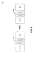
図2にスーパーフレーム構成200の一例を示す。スーパーフレーム200の一例において、付加的なパイロットシンボル−TDM3が一つだけ示されているが、1つ以上の付加的なパイロットシンボルが使用されてもよい。スーパーフレーム構成200により、前方向リンクのみ(FLO)ネットワークにおける複数の広域チャネルおよび複数のローカルエリアチャネルの放送を容易にするための新しいOFDMシンボルが導入される。スーパーフレームにおいて第1のOFDMシンボルは一般には210のTDMパイロット1である。第2のOFDMシンボルTDMパイロット2を220に示す。230の第1のTDMパイロット3がこの順序に続き、240の広域OIS(オーバーヘッド情報シンボル)が続く。一般に、新規の、ローカルエリア、TDMパイロット3シンボル230はローカルエリアOISシンボルの前に挿入することが可能である。このパターンを、通常は、例えば参照数字250で示す広域チャネルおよびローカルエリアチャネルの間のようなすべての接合点で繰り返す。しかしながら、少なくとも2つのシンボルを持つシンボルサブセットを250のような広域およびローカルエリアの間の境界に配置するならば、処理はより単純になる。
FIG. 2 shows an example of the
TDMパイロット2 220と同様に、TDMパイロット3 230などは、4つのヌル奇数インターレース(1,3,5,7)を持つことができる。この場合、偶数インターレース(0,2,4,6)はパイロットによって占められる。TDMパイロット2 220と異なり、TDMパイロット3 230は、広域からローカルエリアへの遷移に位置する場合、偶数で番号付けされた4つのインターレースのうちの3つをローカルエリアパイロットのために用い、1つを広域用とすることができる。あるいは、TDMパイロットIIIがローカルエリアから広域への遷移に位置するならば、3つを広域パイロット用とし、1つをローカルエリア用とすることができる。これは、単一のTPCパイロットを各境界上に展開する実施形態に適用できる。1つの境界当たり2つのTPCシンボルを備える別の実施形態では、ローカルエリア遷移パイロットチャネル(LTPC)シンボルはローカルエリアパイロットが占有する、すべて偶数のインターレース、および広域パイロットによる広域TPC(WTPC)シンボルを持つ。理解できるように、スーパーフレーム200の他の構成も可能である。
Similar to
あるベースラインとして、フレーム200につき290のデータシンボルを使用することが可能である。2つの新規なOFDMシンボル、広域260およびローカルエリア識別270チャネル(WIC& LIC)が、スーパーフレーム200の最初のTDM 1およびTDM 2の間に導入される。スーパーフレーム200の残りの部分には、例えば、20のTDM 3パイロットシンボル250が導入される。概して、TDM 3は広域チャネルおよびローカルエリアチャネルの間の各遷移における1つまたは2つのOFDMシンボルから成る。しかしながら、例外もある。図2において230および280で示されるTDM 3を短いスライスを用いて示したように、最初の広域OISシンボル(WOIS)の前にただ一つのTDM 3シンボルがあり、最終フレームの終端に1つのTDM 3シンボルがある。
As a baseline, 290 data symbols per
290に示す新規の測位パイロットチャネルを付加することが可能である。測位パイロットチャネルはスーパーフレームの終端にPのOFDMシンボルを含む。測位パイロットは受信機が三角測量方法により位置選択を行うのを支援する。

広域TDMパイロット3シンボルおよびローカルエリアTDMパイロット3シンボルの両方を持つ実施形態におけるTDM 3シンボルの位置は、上記テーブル1に示される。1つのフレーム当たりの有用なデータOFDMシンボルの数はFで表され、そのうち、Wが広域チャネルに用いられ、F − Wがローカルエリアチャネルに用いられる。Wは0からFの範囲で変化する。前に述べたように、Fのベースライン値は290とすることができ、これは6つの測位パイロット(すなわちP=6)のベースライン値に対応する。しかしながら、測位パイロットを利用しない場合には、少なくとも2つのシンボルが現在の数秘学的制約により保存されるものとする。P=2の場合、1つのフレーム当たりのシンボル数は290から291に増加することがある。FとPの間の関係の一つは、F=291−(P−2)/4で与えられる。
The location of
唯一のTDMパイロット3シンボルを持つ実施形態について、パイロットの位置を表2および表3に示す。
この実施形態では、10個のTDM3パイロットシンボルが存在する場合、Pの値は4の倍数に制限される。フレーム内のデータシンボルの数はF=294P/4から与えられる。11個のTDM3パイロットシンボルが存在する場合、Pの値は4n+3で表される値に制限される。その後、フレーム内のデータシンボルの数はF=294−(P+l)/4から与えられる。 In this embodiment, if there are 10 TDM3 pilot symbols, the value of P is limited to a multiple of 4. The number of data symbols in the frame is given by F = 294P / 4. If there are 11 TDM3 pilot symbols, the value of P is limited to the value represented by 4n + 3. Thereafter, the number of data symbols in the frame is given by F = 294− (P + 1) / 4.
上記TDMパイロット3シンボルロケーションの説明から、TDMパイロット3シンボルはフレームの一部であるとも解釈することができる。とりわけ、フレーム200は、その先頭が広域TDM3シンボルから始まり、その終端はローカルエリアTDM3シンボルで終わることが可能であり、該2つのTDM3シンボルをフレーム内における広域からローカルエリアへの遷移に含む。このように数えると、1つのフレーム当たりのシンボルの数はF+4であり、これは上記のテーブル1に現われる要素でもある。同様に、OISのまわりのTDM3シンボルはOISに含めることが可能である。その結果、7つの広域OISおよび7つのローカルエリアOISシンボルが得られ、各OIS過程はTDM3シンボルで終わる。TDM3シンボルをフレームとOISのどちらの一部と見なすかは取り決めの問題であるが、これをハードウェアの都合によって推してもよい。単一のTPCシンボルを持った実施形態では、F+3シンボルを含んでいる1つのフレーム(1位または最後)以外は、1つのフレーム当たり概してF+2シンボルがあるので、そのような単純な類比はできない。
From the above description of the
図3は、TDM3シンボル300の具体的なブロック図である。図示のように、310の左のTDMパイロット3シンボルはローカルエリアチャネルと広域のチャネルの間に位置することが可能である。(0,3,6)時差パターンを満たすように、TDMパイロット3 310のどのインターレースがローカルエリアチャネル推定に用いられるかは、最後のローカルエリアOFDMシンボルのパイロットインターレースによって決定することができる。具体例300において、インターレース7がローカルエリアチャネルの最後のOFDMシンボルによって使用されるので、TDMパイロット3のインターレース2はローカルエリアチャネルパイロットに使用される。広域パイロットに他の3つのインターレースを使用することが可能であることから、最初の広域OFDMシンボルのためのパイロットインターレースは(0,3,6)時差パターン満たすための3つの選択肢を持つ。インターレースは、隣接する広域放送間のパイロット衝突の可能性を低減するために、広域放送IDに基づいた3つの可能性から無作為に選ばれる。TDMパイロット3が3つの広域パイロットインターレース(3/4広域チャネル情報を含んでいる)を有するので、それは、最初の広域OFDMシンボルのサンプリングの前の、広域チャネルへのAGC収束を支援する。320に示す正しいTDMパイロット3シンボルは広域およびローカルエリアの遷移間に位置する。最後の広域チャネル推定に用いられるインターレースは、(0,3,6)時差パターン要求が満たされる最後の広域OFDMシンボルのパイロットインターレースによって決定される。最初のローカルエリアOFDMシンボルのパイロットインターレースは、(0,3,6)時差パターンは、隣接するローカルエリア放送の中のパイロット衝突の可能性を低減するために保存されよう、3つの可能性から無作為に選ばれる。TDMパイロット3は3つのローカルエリアパイロットを持つので、最初のローカルエリアOFDMシンボルのサンプリングの前の、ローカルエリアチャネルへのAGC収束を支援する。
FIG. 3 is a specific block diagram of the
図4は複数のTDMパイロット3シンボルが使用される場合の他の実施形態を示す。この実施形態では、2つの付加的なパイロットシンボルがローカルエリアおよび広域のデータ境界間で運用される。これは、ローカルエリア遷移パイロットチャネル(LTPC)シンボルおよび広域遷移パイロットチャネル(WTPC)シンボルがシンボルのサブセットとして410および420に示される。420に示すように、LTPCとWTPCのそのようなグループ分けは、OFDM構成に現われるローカルエリア境界および広域境界の間に見られる。一般に、LTPCはローカルエリアデータ構造の最後のパケットを復号するために使用され、ここで、最後のローカルエリアシンボルをローカルエリアシンボルLと呼ぶことにする。したがって、それぞれの受信機は、最後のローカルエリアシンボルLを決定するために、ローカルエリアシンボルL、ローカルエリアシンボルL−IおよびそれぞれのLTPCを含む3つのシンボルパケットを処理するはずである。最初の広域シンボルNに対して復号すれば、受信機復号用の3つのシンボルパケットは、WTPC、最初の広域シンボルNおよび次の広域シンボルN+1のはずである。2つ以上のTDM3シンボルをローカルエリア境界および広域データ境界の間で使用することも可能であることは十分に理解される。
FIG. 4 shows another embodiment where
LTPCおよびWTPCに使用されるTDM3のシンボル構成はノーマルデータシンボルに類似している。これは、占められた8つのスロットを含み、それぞれのデータシンボルはスクランブル化の前にすべて「0」である。ここで、インターレースはキャリアのサブセットである。また、スロットはインターレースの充てんをランダム化するためにインターレースに対してマップされる。シードおよびマスクをスクランブルすることにより、スロットからインターレースへのマッピングおよび変調シンボルのエネルギーはデータシンボルに見られるものと類似する。特に、広域TDM3シンボル−WTPCはシードにおいて広域IDを用いてスクランブルされ、ローカルエリアTDM3シンボル−LTPCは、シードにおいて広域IDおよびローカルエリアIDの両方を用いてスクランブルされる。一般に、受信機は、1つの具体的なモデム実装におけるTDM3の位置を決定する必要はない。しかしながら、TDM3位置に関する情報を送ることのオーバヘッドはとても小さく、TDM3に基づいたウェイクアップ時間トラッキングおよびタイミング同期の改良パスとして有用かもしれない。 The symbol structure of TDM3 used for LTPC and WTPC is similar to normal data symbols. This includes 8 occupied slots, and each data symbol is all “0” prior to scrambling. Here, interlace is a subset of carriers. Slots are also mapped to interlaces to randomize interlace filling. By scrambling the seed and mask, the slot-to-interlace mapping and modulation symbol energy is similar to that found in data symbols. In particular, the wide area TDM3 symbol-WTPC is scrambled with the wide area ID in the seed, and the local area TDM3 symbol-LTPC is scrambled with both the wide area ID and the local area ID in the seed. In general, the receiver need not determine the location of TDM3 in one specific modem implementation. However, the overhead of sending information about TDM3 location is very small and may be useful as an improved path for wake-up time tracking and timing synchronization based on TDM3.
図5は、前方向リンクのみネットワークに対するエアインターフェース検討500の一例を示している。510に進んでシンボルロケーションについて検討する。ここではパケットを分析し、シンボルがそれぞれのパケット内のどこに配置されるかを決定する。図5の520に示される、スロットからインターフェースへのマッピングの検討について述べる。1つのTDMパイロット3シンボルを境界に持つ実施形態を考慮すると、典型的には、TDMパイロット3シンボルの各々は同じ構成を有する。最初の4つのスロットは各OFDMシンボル(すなわちスロット0,1,2,3)において用いられる。スロットからインターレースへのマッピングは、TDM3について、これらのスロットが偶数のインターレース0,2,4,6に対してマップされるように選ばれる点が特有である。TDM3が偶数インターレースを占有するのを制限することは、このシンボルに基づいたタイミング同期を簡素化する。具体的には、TDM3について、スロットからインターレースへのマッピングをfTDM3(n,s)とする。ただし、nはシンボルインデックス、sはスロットインデックスである。次に、マッピングをfTDM3(n,0)=fPrev(n,0)、fTDM3(n,s)=[fTDM3(n,s−1)+2] mod 8,s=1,2,3(式1)と定義する。
FIG. 5 shows an example of an
ここで、fPrev(n,s)は、前の多重化についてのスロットからインターレースへのマッピング関数を意味する。したがって、広域からローカルエリアへの遷移について、fPrev(n,s)は広域OFDMシンボル用の、スロットからインターレースへのマッピングである。また、広域からローカルエリアへの遷移について、fPrev(n,s)はローカルエリアOFDMシンボル用の、スロットからインターレースへのマッピングである。なお以下の説明では、TDM 3における「パイロット」インターレースは、直前の多重化のためのパイロットに相当する。また、続く多重化は、時間をフィルタリングことのためにパイロットインターレースを必要とするかもしれない。そしてこのパイロットインターレースは、残り3つのインターレースのうちのいずれかになるはずである。スロット0は、一般に、次の多重化のためのパイロットインターレースには関係しない。その1つの理由は、パイロットインターレースを単独で用いる代わりに、時間フィルタリングプロセスをブートストラップするために、次のシンボルが、TDM 3における3つのインターレースすべてからのチャネル推定を用いることができるからである。このブーツストラッピングは、TDM 2と最初の広域OISシンボルとの間ででなされるものと類似している。
Here, f Prev (n, s) means a slot-to-interlace mapping function for the previous multiplexing. Thus, for the transition from wide area to local area, f Prev (n, s) is a slot-to-interlace mapping for wide-area OFDM symbols. For the transition from the wide area to the local area, f Prev (n, s) is a slot-to-interlace mapping for the local area OFDM symbol. In the following description, the “pilot” interlace in
上式1の背後に潜む1つの側面は以下の通りである。スロット0は常にパイロットスロットであることから、第1の式は、前の多重化から途切れることなくパイロットをふらつかせることが容易に行える。例えば、パイロットがフレームにおける最後の広域シンボル内のインターレース3に達すれば、それはTDM 3のインターレース6に出現する。同様に、パイロットが最後のローカルエリアシンボルのインターレース7に達すれば、該パイロットはTDM 3におけるインターレース2上に存在する。これらの例から、TDM 3シンボルが偶数のインターレースを持つことを可能とするためには、Wは奇数である、という制約が当てはまることは明らかである。
One aspect lurking behind Equation 1 is as follows. Since slot 0 is always a pilot slot, the first equation can easily stagger the pilot without interruption from the previous multiplexing. For example, if the pilot reaches
なお上記の制約は、領域境界に一つのTDMパイロット3を持った実施形態にのみ必要である。1を超えるTDMパイロット3シンボルが領域境界に認められる場合、Wは任意の値をとることが可能である。境界にただ一つのTDMパイロット3を持った実施形態についての、このWの制限は、fPrev(n−1,0)は奇数であり、fTDM3(n,0)が偶数であることを保証する。スロット0に対応するパイロットインターレースが選ばれる場合、それらが、残る偶数のインターレースに位置するように、スロット1,2,3がマップされる。例えば、パイロットインターレースが2である場合、スロット1,2,3をインターレース0,4,6にマップする。これを達成する一つの方法は、パイロットインターレースからスタートし、残りの偶数インターレース中を循環する、式1における第2の等式から与えられる。そのようなマッピングはハードウェア実装の点で都合が良い。
Note that the above restriction is necessary only in an embodiment having one
ある態様において、最初の4つのスロットについてのみマッピングを定義する。実装の観点では、スロットをすべてマップする必要がある場合、スロット4〜7は恐らくルックアップ表を用い、任意のやり方で奇数のインターレースに対してマップすることが可能である。また、fTDM3(n,s)=2(s−4)+1,s=4,5,6,7とし、例えばスロット4をインターレース1にマップし、スロット5をインターレース3にマップするなど、決定論的なマップを算出することも可能である。 In some aspects, mapping is defined only for the first four slots. From an implementation point of view, if all slots need to be mapped, slots 4-7 can be mapped to odd interlaces in any way, perhaps using a look-up table. Also, f TDM3 (n, s) = 2 (s−4) +1, s = 4, 5, 6, 7 is determined, for example, slot 4 is mapped to interlace 1, slot 5 is mapped to interlace 3, etc. It is also possible to calculate a theoretical map.
図5の530に示すスクランブル化について説明する。TDM 3は偶数のインターレースを使うので、スクランブル化は、偶数のインターレースを使うTDM 2に類似している。1つの違いは、TDM 2のためのスクランブル化は、広域ID(すなわちWOI ID)のみに基づくのに対し、TDM 3のスクランブル化は、広域IdおよびローカルエリアIdを使用することである。具体的には、各スロットの500の配列シンボルは、20タップの線形帰還シフトレジスタ(LFSR)に基づいたスクランブラーを用い、1000ビットの系列を生成することにより得ることが可能である。続いて、配列シンボルは隣接ビットの各組をQPSKアルファベットにマップすることにより作成される。TDM 3のためのスクランブラーのシードは、OISおよびデータチャネルにおけるOFDMシンボルについて現在のシードを設定するのに用いた同じ原理に基づいている。スクランブラーシードは、長さが20ビットであり、[d3d2d1d0c3c2c1c0c0b0a10a9a8a7a6a5a4a3a2a0a0]の形式である。
The scramble process shown at 530 in FIG. 5 will be described. Since
TDM 3のスロットについては、表2に規定されるように、b0は「1」にセットされる。また、a10...a0はスーパーフレーム中のOFDMシンボルインデックスに対してセットされる。さらに、d3d2d1d0が4ビット広域IDに対してセットされる。c3c2c1c0の値はスロットインデックスおよび遷移、すなわち広域→ローカルエリアまたはローカルエリア→広域、の種類に依存する。これらの値は下のような表2に要約される。
なお、広域パイロットの送信に用いられるスロットについては、WDDおよびLDDのために、他の広域スロット送信と同じセッティングを用いることのみが一般に要求される。同様に、ローカルエリアパイロットの送信に用いられるスロットについては、WDDおよびLDDのために、他のローカルエリアスロット送信と同じセッティングを用いることが一般に要求される。 Note that for slots used for wide area pilot transmission, it is generally required to use the same settings as other wide area slot transmissions for WDD and LDD. Similarly, for slots used for local area pilot transmissions, it is generally required to use the same settings for other local area slot transmissions for WDD and LDD.
540に示すマスク検討について説明する。上に記述された、スクランブルをかける動作は、用いられるマスクのみならずシードによっても決定される。8つのマスクがリストされる場合、マスクはスロットインデックスに依存してもよい。TDM 3のスロット0−3に対応するマスクを同様に用いることが可能である。マスクについての他の選択も可能であることは理解されるであろう。
The mask study shown at 540 will be described. The scrambling action described above is determined by the seed as well as the mask used. If 8 masks are listed, the masks may depend on the slot index. Masks corresponding to slots 0-3 of
図6に、付加的なエアインターフェース検討600を示す。610に進み、スロットエネルギーについて検討する。TDM 3が8つのスロットのうちの4つを使用することから、同OFDMシンボルエネルギーの全体を維持するために、各スロットのエネルギーを2倍にする場合がある。しかしながら、TDM 3のためのスロットは、2つのグループ−前の多重化用の1つのパイロットスロット(0)および次の多重化に用いられる3つのスロット(1,2,3)−に現われる。したがって、すべてのスロットエネルギーを同一の要素でスケーリングすべきかは明らかではない。このスケーリングに関するいくつかの結論は次のとおりである。
FIG. 6 shows an additional
AGC動作:受信機のAGCで、当該シンボル単独でのエネルギー低下が起こらないように、他のOFDMシンボルと同様に合計エネルギーが維持されるものとする。この合計エネルギーをEとする。 AGC operation: It is assumed that the total energy is maintained in the same manner as other OFDM symbols so that the energy drop of the symbol alone does not occur in the AGC of the receiver. Let this total energy be E.
直前の多重化の時間フィルタリング:広域/ローカルエリア多重化の最後のシンボルについてはタイムフィルターの係数を修正しない。このため、スロット0のエネルギーはE/8であるものとする。 Immediate multiplexing time filtering: The time filter coefficients are not modified for the last symbol of wide area / local area multiplexing. For this reason, the energy of slot 0 is assumed to be E / 8.
続く多重化の時間フィルタリング:タイムフィルターを修正することが可能でない場合、続く多重化のためのパイロットスロットはエネルギーE/8を有するものとする。しかしながら、これには、送信機が続く多重化のためのパイロットスロットを識別することが必要となるかも知れない。現在のスキームでは、スロット1と2および3の間に区別はなく、このパイロットスロットはスロット番号ではなくインターレースによって識別される。従って、上式1を用いることによりパイロットインターレース番号からパイロットスロット番号まで戻る必要があるかも知れない。しかし、パイロットスロットを識別することが可能であるならば、その前にTDM 3が存在することをチャネル推定では無視することができる。
Subsequent multiplexing time filtering: If it is not possible to modify the time filter, the pilot slot for subsequent multiplexing shall have energy E / 8. However, this may require the transmitter to identify the pilot slot for subsequent multiplexing. In the current scheme, there is no distinction between
続く多重化のためのタイミング同期:続く多重化のためのタイミング同期は、スロット1、2および3に対応するインターレースに基づいて行うことができる。この動作はTDM 3に特有なものであるから、いくらかのエネルギー割当てを計上するために、容易に修正することが可能である。ただし、受信機はTDM 3シンボルインデックスを知っているものとする。
Timing synchronization for subsequent multiplexing: Timing synchronization for subsequent multiplexing can be based on the interlaces corresponding to
RxのFFTのための2kサンプル対4kサンプル:最終のスロットエネルギースケーリングは、TDM 3のためのFFTが受信機にどのように実行されるかにも依存する。(ノーマルデータ復調について行われたように)4kサンプルが各インターレースにつき512のFFTを得るのに用いられる場合、スロットエネルギーがすべてキャプチャーされる。一方、2kサンプルのみが(TDM 2について行われたように)用いられる場合、スロットエネルギーは事実上、二等分される。ただし、受信機は、2kサンプルしか用いないようにTDM 3シンボルインデックスを知っていることが必要である。これらの検討に基づいて、スロット3にスロット0に対する、1){E/4,E/4,E/4,E/4}、2){E/8,7E/24,7E/24,7E/24}、3) {E/8,E/8,3E/8,3E/8}という3つのエネルギー割当てが可能である。ただし、設計を単純にするには、1番目の割当てが推奨される。これにより実効スロットエネルギーはE/8になる。したがって、直前の多重化または続く多重化についてタイムフィルターを変更する必要はない。
2k samples vs 4k samples for Rx FFT: Final slot energy scaling also depends on how the FFT for
図6の620に進み、後方にスロットをマッピングする検討について説明する。一般に、スロット0−7は、広域OIS、FDMパイロットおよびデータOFDMシンボル用のインターレースにマップされる。マッピングは、TDM2、ならびに広域識別シンボルおよびローカルエリア識別シンボルに対しても適用可能とするために、「後方に」拡張することが可能である。マッピングは、1−1199の範囲の値を持つ、スーパーフレーム内のOFDMシンボルインデックスを用いるが、56のOFDMシンボルごとにそれ自体を繰り返す。ある具体例において、fWOI(n,s)はスロットからインターレースへのマップを意味する。ただし、nはスーパーフレーム内のOFDMシンボルインデックス、sはスロットインデックスである。スロット0は当該スキームのパイロットであり、fWOI(n,0)はパイロットインターレースである。チャネル推定のための時間フィルタリングは直前および後続の多重化について演算を行うという制約の下、ローカルエリア多重化のための、スロットからインターレースへのマップは同様に変更されるものとする。 Proceeding to 620 in FIG. 6, a discussion of mapping slots back is described. In general, slots 0-7 are mapped to interlaces for wide area OIS, FDM pilot and data OFDM symbols. The mapping can be extended “backward” in order to be applicable to TDM2 as well as wide and local area identification symbols. The mapping uses OFDM symbol indices within the superframe, with values ranging from 1-1199, but repeats itself for every 56 OFDM symbols. In one embodiment, f WOI (n, s) means a slot to interlace map. Here, n is the OFDM symbol index in the superframe, and s is the slot index. Slot 0 is the pilot of the scheme, and f WOI (n, 0) is a pilot interlace. Under the constraint that temporal filtering for channel estimation operates on previous and subsequent multiplexing, the slot-to-interlace map for local area multiplexing shall be similarly modified.
スロットからインターレースへのマッピングを変更する理由の一つを、ある一例を通して見ることができる。広域多重化とローカルエリア多重化の間の遷移について検討する。この遷移におけるTDM 3のOFDMシンボルインデックスをn0とする。また、最後の広域OFDMシンボルがインターレース3(すなわちfWOI(n0−1,0)=3)にパイロットを有するものとみなすそして、TDM 3のスロット0(fWOI(n0,0)=6)をインターレース6にマップする。このマップは、最後の広域シンボルのための時間フィルタリングを可能にする。しかし、もし同じマッピングをローカルエリア多重化に用い続ければ、第一のローカルエリアシンボルのためのパイロットインターレースはfWOI(n0+1,0)=1になる。最初のローカルエリアシンボルのための時間フィルタリングは、シンボルn0,n0+1,n0+2における、インターレース6、1および4のパイロットをそれぞれ必要とするが、これらは利用可能ではないかも知れない。なぜなら、TDM 3におけるインターレース6は、広域用のパイロットとして既に用いられているからである。パイロットとしてのスロット1、2または3のうちの1つは、ローカルエリアシンボルに用いられるはずである。
One reason for changing the slot-to-interlace mapping can be seen through an example. Consider the transition between wide area multiplexing and local area multiplexing. Let the OFDM symbol index of
ローカルエリアシンボルについて新規のスロットからインターレースへのマッピング関数をfLOI(n,s)とする。これを、上記の具体例から、新規のマッピングに対する汎用の制約に一般化することが可能である。本来、広域パイロットおよびローカルエリアパイロットはTDM 3において異なるインターレース上に存在する。従って、[fWOI(n0,0)−fLOI(n0,0)] mod 8=2,4,または6である。これを容易にする単純な方法の一つは、広域マップのタイムシフトとしてローカルエリアマップを得ることである。以下6つのマップのうちのいずれかはfLOI(n,s)=fWOI(n+2m,s),m=±1,±2,±3をはずである。パイロットインターレースが偶数により異なるものとなるよう、広域マップを偶数(しかし8の倍数ではない)のOFDMシンボルにシフトすることが可能である。単純化のためには、次のマップ、すなわちfLOI(n,s)=fWOI(n+2,s)(式2)を推奨する。
Let f LOI (n, s) be a new slot-to-interlace mapping function for local area symbols. This can be generalized from the above specific example to a general purpose constraint on the new mapping. Essentially, wide area pilots and local area pilots exist on different interlaces in
式2によって定義された、スロットからインターレースへのマップは、ローカルエリアOISチャネル、ローカルエリアデータ・チャネルおよびローカルエリアFDMパイロットチャネルに適合する。新規の、スロットからインターレースへのマップを用いることに加え、ローカルエリアOISチャネル、データチャネルおよびFDMパイロットチャネルについては、多少、スクランブル化演算を修正すべきである。上述したように、20ビットのスクランブラーシードは4ビットの広域部分および4ビットのローカルエリア部分を有する。広域チャネルについては、広域部分はWIDにセットされる。また、ローカルエリア部分はデフォルトLID値にセットされる。ローカルエリアデータ/OIS/FDMパイロットのローカルエリア部分は送信機のLIDであるが、広域部分にはWIDが常にセットされる。
The slot-to-interlace map defined by
図6の630に進み、MAC層検討について説明する。MAC層で変更可能なことを強いて挙げると、広域シンボルおよびローカルエリアOFDMシンボルの間の境界、ならびにローカルエリアシンボルおよび測位パイロットシンボルの間の境界に関して情報を送信する規定がある。この情報は、続く多重化のタイミング同期を容易化し、境界での時間フィルタリングのための基準要素決定を支援するために送信すべきとされる。境界情報を送ることは、可変であるTDM3の位置を送ることと等価とみなすことができる。W(広域データOFDMシンボルの数)およびP、すなわち使用されている測位パイロットの数が既知であれば、上記表2から、TDM 3の位置は決定される。
Proceeding to 630 in FIG. 6, the MAC layer study will be described. To force it to be changeable at the MAC layer, there is a provision for transmitting information regarding the boundary between the wide area symbol and the local area OFDM symbol and the boundary between the local area symbol and the positioning pilot symbol. This information should be transmitted to facilitate timing synchronization of subsequent multiplexing and to assist in determining reference elements for temporal filtering at the boundary. Sending boundary information can be considered equivalent to sending a variable TDM3 location. If W (number of wide area data OFDM symbols) and P, that is, the number of positioning pilots used is known, the position of
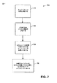
図7は、無線システムのパイロットシンボルプロセス700を示している。説明を平易化することを意図し、本方法を一連の、または多数のアクトとして示し説明するが、ここに記述されたプロセスは、アクトの順序によって限定されないことが理解され、了解される。いくつかのアクトは、異なる順序で生じてもよく、および/または、いくつかのアクトが、ここに示され説明されたもののうちの他のアクトと同時に生じてもよい。例えば当業者は、状態遷移図に見られるような一連の相互関係を持つ状態またはイベントとして方法を表現可能であるかも知れないことを理解し了解するであろう。さらに、ここに開示され、対象としている方法に従ってある方法を実装するにあたっては、必ずしもここに示されたすべてのアクトが要求されるとは限らない。
FIG. 7 shows a
710に進む。1つまたはそれ以上のスーパーフレーム制約を、付加的なTDMパイロットシンボルを使用することを考慮して決定する。上記のとおり、これにはシンボルロケーション、スロットマッピング検討、スクランブル化検討、マスク検討、スロットエネルギー検討、後方互換性検討が含まれ、現在のMAC層フレームワークに影響を与える。理解されるように、OFDM放送の送信機になされた変更は、受信機側でも明らかにされ、検討されるであろう。720における、付加的なTDMパイロット制約について検討する。ある態様において、これには、TDM1およびTDM2の従来のシンボルセットに対して付加する付加的なシンボルは幾つであるかを決定することを含むことができる。 Proceed to 710. One or more superframe constraints are determined in view of using additional TDM pilot symbols. As noted above, this includes symbol location, slot mapping considerations, scrambling considerations, mask considerations, slot energy considerations, and backward compatibility considerations, which impact the current MAC layer framework. As will be appreciated, changes made to the transmitter of an OFDM broadcast will be revealed and considered on the receiver side as well. Consider additional TDM pilot constraints at 720. In certain aspects, this may include determining how many additional symbols to add to the TDM1 and TDM2 conventional symbol sets.
一般に、1つの付加的なTDM3が含まれていてもよいが、1以上のシンボルをスーパーフレームおよび関連する仕様、に対して加えることが可能である。他の検討は、全体的なスーパーフレーム構成について710で決定される1つまたはそれ以上の制約を含んでいる。730では、少なくとも1つの付加的なTDMパイロットシンボルがスーパーフレーム構成に付加される。上記のとおり、最初の付加的なパイロットは一般にTDM2に従うのであり、続く付加的なパイロットが、ローカルエリア情報放送と広域情報放送の間のセパレーションに用いられる。理解されるように、他の構成も可能である。740では、付加的なパイロットが受信機でのタイミング同期、チャネル推定および/またはAGCブートストラッピングを支援するためにスーパーフレームに対して加えられた場合
図8は、ここに説明された1つ以上の態様に従って、無線通信環境において使用されるユーザ機器800の具体例を示したものである。ユーザ機器800は、例えば受信アンテナ(不図示)から信号を受信し、例えばフィルタ、増幅器、ダウンコンバータなどが受信信号に対して特有の動作を行い、サンプルを得るために条件信号をディジタル化する受信機802を含む。復調器804は、受信パイロットシンボルを復調し、チャネル推定用プロセッサ806に提供することができる。プロセッサ806は、受信機802により受信された情報の解析し、および/または送信機816による送信のための情報を生成する専用プロセッサとすることができ、ユーザ機器800の1つ以上のコンポーネントを制御するプロセッサとすることができる。および/またはプロセッサ806は、受信機802により受信された情報を解析するとともに送信機816による送信のための情報を生成すること、ユーザ機器800の1つ以上のコンポーネントを制御することの両方を行うプロセッサとすることができる。ユーザ機器800は、プロセッサ806に対して動作可能に接続されるメモリ808をさらに含むことが可能である。
In general, one additional TDM3 may be included, but one or more symbols can be added to the superframe and associated specifications. Other considerations include one or more constraints determined at 710 for the overall superframe configuration. At 730, at least one additional TDM pilot symbol is added to the superframe structure. As described above, the first additional pilot generally follows TDM2, and subsequent additional pilots are used for separation between local area information broadcast and wide area information broadcast. As will be appreciated, other configurations are possible. At 740, if additional pilots are added to the superframe to support timing synchronization, channel estimation and / or AGC bootstrapping at the receiver, FIG. 8 illustrates one or more of the features described herein. 4 illustrates a specific example of a
ここに記述されたデータストア(例えばメモリ)コンポーネントは、揮発性メモリまたは持久記憶装置のいずれかとすることができ、または揮発性・持久記憶装置の両方を含むことが可能であることは十分に理解される。制限ではなく具体例として、持久記憶装置は読み取り専用メモリ(ROM)、プログラマブルROM(PROM)、EPROM(EPROM)、EEROM(EEPROM)またはフラッシュメモリを含むことが可能である。揮発性メモリはランダムアクセスメモリ(RAM)を含むことが可能である。それは外部キャッシュメモリとして働く。制限ではなく具体例として、RAMとしては、シンクロナスRAM(SRAM)、ダイナミックRAM(DRAM)、シンクロナスDRAM(SDRAM)、ダブルデータレートSDRAM(DDR SDRAM)、エンハンストSDRAM(ESDRAM)、Synchlink DRAM(SLDRAM)およびダイレクトRambus RAM(DRRAM)のような多くの形態が利用可能である対象システムおよび方法のメモリ808は、制限されずに、これらおよび他の適切なタイプのメモリを含むことが意図される。
It is well understood that the data store (eg, memory) components described herein can be either volatile memory or persistent storage, or can include both volatile and persistent storage. Is done. By way of example and not limitation, the permanent storage device may include read only memory (ROM), programmable ROM (PROM), EPROM (EPROM), EEROM (EEPROM) or flash memory. Volatile memory can include random access memory (RAM). It acts as an external cache memory. As a specific example, not as a limitation, the RAM may be a synchronous RAM (SRAM), a dynamic RAM (DRAM), a synchronous DRAM (SDRAM), a double data rate SDRAM (DDR SDRAM), an enhanced SDRAM (ESDRAM), a Synclink DRAM (SLDRAM). ) And direct rambus RAM (DRRAM) and many other forms of available target system and
図9は、システム900の一例を示す。このシステム900は、複数の受信アンテナ906を通じて、1つ以上のユーザ機器904から信号を受信する受信機910、および送信アンテナ908を通じて1つ以上のユーザ機器904に対して送信を行う送信機924を備えた基地局902を含む。受信機910は受信アンテナ906から情報を受信することが可能であり、受信された情報を復調する復調器912と動作可能に関係づけられている。復調されたシンボルは、上に記述されたプロセッサに類似するプロセッサ914によって解析される。このプロセッサ914は、利用者ランク、関係するルックアップテーブル、および/または、ここに説明された様々な作用および機能の実行に関する他の適当な情報を格納するメモリ916に接続されている。モジュレータ922は、送信アンテナ908を通じて送信機924がユーザ機器904に対して送信する送信信号の多重化を行うことが可能である。基地局902は、情報を提供し、非線形の受信機に関連してデコーディングプロトコルを使用するユーザ機器90と交信することが可能である。
FIG. 9 shows an example of a
図10は模範的な無線通信システム1000を示す。この無線通信システム1000には、簡潔さのために1つの基地局および1つの端末が示される。しかしながら、システムが1つ以上の基地局および/または1つ以上の端末を含むことが可能であることは十分に理解される。
FIG. 10 shows an exemplary
今、図10を参照すると、ダウンリンク上のアクセスポイント1005では、送信(TX)データプロセッサ1010がトラフィックデータを受信し、フォーマットし、コード化し、インタリーブし、変調する(あるいはシンボルマップする)。そそして送信(TX)データプロセッサ1010は変調シンボル(「データシンボル」)を提供する。シンボルモジュレータ1015はデータシンボルおよびパイロットシンボルを受信して処理し、シンボルのストリームを提供する。シンボルモジュレータ1020はデータおよびパイロットのシンボルを多重化し、送信機ユニット(TMTR)1020にそれらを与える。送信シンボルはそれぞれ、データシンボル、パイロットシンボルまたは0値の信号とすることができる。パイロットシンボルは、各シンボル周期で連続的に送られてもよい。パイロットシンボルは、周波数分割多重化(FDM)、直交周波数分割多重化(OFDM)、時分割多重化(TDM)、周波数分割多重化(FDM)、あるいは符号分割多重化(CDM)が行われ得る。
Referring now to FIG. 10, at an access point 1005 on the downlink, a transmit (TX)
TMTR 1020は、シンボルのストリームを受信してこれを1つ以上のアナログ信号に変換し、さらに無線チャネルへの送信に適したダウンリンク信号を生成するよう該アナログ信号を調整する(例えば増幅し、フィルタ処理し、周波数アップコンバートする)。その後、ダウンリンク信号は、端末に向けてアンテナ1025を介して送信される。端末1030では、アンテナ1035がダウンリンク信号を受信し、受信機ユニット(RCVR)1040に受信信号を供給する。受信機ユニット1040は受信信号を調節(例えばフィルタ処理し、増幅し、周波数ダウンコンバート)し、該調整された信号を、サンプルを得るためにディジタル化する。シンボル復調器1045は、受信パイロットシンボルを復調し、チャネル推定用のプロセッサ1050に提供する。さらにシンボル復調器1045は、プロセッサ1050からダウンリンク用の周波数応答推定を受信し、データシンボル推定(それらは送信データシンボルの推定である)を得るために受信データシンボル上でデータ復調を実行し、およびRXデータプロセッサ1055にデータシンボル推定を提供する。RXデータプロセッサ1055は、送信されたトラフィックデータを取り出すためにデータシンボル推定を復調(すなわちシンボルデマッピング)し、デ・インタリーブし、デコードする。シンボル復調器1045およびRxデータプロセッサ1055による処理は、アクセスポイント1005における、シンボルモジュレータ1015およびTXデータプロセッサ1010によるそれぞれの処理に対して相補的である。
アップリンクにおいては、TXデータプロセッサ1060がトラフィックデータを処理し、データシンボルを提供する。シンボルモジュレータ1065は、パイロットシンボルを持ったデータシンボルを受信して多重化し、変調を行い、シンボルのストリームを提供する。その後、送信機ユニット1070は、アップリンク信号を生成するためにシンボルのストリームを受信して処理する。該アップリンク信号はアンテナ1035によりアクセスポイント1005に送信される。
On the uplink, a
アクセスポイント1005では、端末1030からのアップリンク信号がアンテナ1025によって受信され、サンプルを得るために受信機ユニット1075によって処理される。その後、シンボル復調器1080はサンプルを処理し、受信パイロットシンボルおよびデータシンボル推定をアップリンク用に提供する。Rxデータプロセッサ1085は、端末1030によって送信されたトラフィックデータを取り出すためにデータシンボル推定を処理する。プロセッサ1090は、送信を行っている個々のアクティブな端末についてのチャネル推定を実行する。複数の端末が、パイロットサブバンドのそれぞれの割り当てられたセットについて、アップリンク上でパイロットを同時に送信してもよい。該パイロットサブバンドセットはインターレースされる。
At access point 1005, the uplink signal from terminal 1030 is received by
プロセッサ1090および1050は、それそれ、アクセスポイント1005および端末1030に動作を向ける(例えば、制御する統合、管理するなど)。それぞれのプロセッサ1090および1050は、プログラムコードおよびデータを格納するメモリユニット(不図示)に関連づけることが可能である。プロセッサ1090および1050は、アップリンクおよびダウンリンク用の周波数およびインパルス応答の推定を得るためにそれぞれ演算を実行することが可能である。
多重アクセスシステム(例えばFDMA、OFDMA、CDMA、TDMAなど)に関しては、複数の端末がアップリンク上で同時に送信をすることが可能である。そのようなシステムについては、パイロットサブバンドを様々な端末間で共有してもよい。チャネル推定技術は、各端末のパイロットサブバンドが動作帯域全体(ことによると帯端を除いて)にまたがる時に用いることができる。そのようなパイロットサブバンド構成は各端末用の周波数ダイバーシティを得るためには望ましい筈である。ここに記述された技術は、様々な手段によって実装することができる。例えば、これらの技術はハードウェア、ソフトウェアまたはこれらの組合せで実装されてもよい。ハードウェア実装については、チャネル推定に用いられる処理ユニットは、1つ以上の特定用途向けIC(ASIC)、デジタル信号プロセッサ(DSP)、ディジタル信号処理デバイス(DSPD)、プログラマブルロジックデバイス(PLD)、フィールドプログラマブルゲートアレー(FPGA)、プロセッサ、コントローラ、マイクロコントローラ、マイクロプロセッサ、ここに記述された機能を実行するよう設計される他の電子機器、またはそれらの組合せで実装してもよい。実装は、ここに記述された機能を実行するモジュール(例えば手順、機能など)によってソフトウェアで行われてもよい。該ソフトウェアのコードがメモリユニットに格納され、プロセッサ1090および1050によって実行されてもよい。
For multiple access systems (eg, FDMA, OFDMA, CDMA, TDMA, etc.), multiple terminals can transmit simultaneously on the uplink. For such a system, pilot subbands may be shared between various terminals. Channel estimation techniques can be used when the pilot subband of each terminal spans the entire operating band (possibly except for the band edge). Such a pilot subband configuration should be desirable to obtain frequency diversity for each terminal. The techniques described herein can be implemented by various means. For example, these techniques may be implemented in hardware, software, or a combination thereof. For hardware implementations, the processing units used for channel estimation are one or more application specific ICs (ASICs), digital signal processors (DSPs), digital signal processing devices (DSPDs), programmable logic devices (PLDs), fields A programmable gate array (FPGA), processor, controller, microcontroller, microprocessor, other electronic device designed to perform the functions described herein, or combinations thereof may be implemented. Implementation may be performed in software by modules (eg, procedures, functions, etc.) that perform the functions described herein. The software code may be stored in a memory unit and executed by the
ソフトウェア実装について、ここに記述された技術は、ここに記述された機能を実行するモジュール(例えばプロシージャ、関数など)で実装されてもよい。該ソフトウェアのコードはメモリユニットに格納され、プロセッサによって実行されてもよい。メモリユニットはプロセッサ内で実装されるか、またはプロセッサの外部で実装されてもよく、その場合、当該技術分野で知られるように、メモリユニットを、様々な手段を介してプロセッサに対して通信可能に接続することができる。 For software implementation, the techniques described herein may be implemented with modules (eg, procedures, functions, etc.) that perform the functions described herein. The software code may be stored in a memory unit and executed by a processor. The memory unit may be implemented within the processor or external to the processor, in which case the memory unit can communicate to the processor via various means, as is known in the art. Can be connected to.
これまでに説明されたことは、模範的な実施形態を含む。実施形態について記述する目的で構成要素または技法の考えられるあらゆる組合せを説明することは当然不可能であるが、当該技術分野において通常の技能を有する者であれば、多くのさらなる組合せおよび置換が可能であることを認識することができる。従って、これらの実施形態は、添付の特許請求の範囲の趣旨および範囲内における変更、修正およびバリエーションのようなものをすべて包含することが意図される。更に、用語「含む(include)」が詳細な説明または特許請求の範囲のいずれかで用いられる範囲において、この用語は、請求項で遷移語として使用された時、「具備する(comprising)」が解釈される場合の用語「具備する」と同様に、包括的であることが意図される。
[付記]
(1)多重キャリア通信システムにおいて情報をマルチキャストする方法であって、
伝送ブロックを生成すること、および
前記伝送ブロックのデコーディングを容易にするために、広域波形とローカルエリア波形との間の遷移に少なくとも1つのTDMパイロットシンボルを挿入することを含む方法。
(2)OFDM(直交周波数分割多重)を利用するマルチキャリア通信システムを使用することをさらに含む(1)の方法。
(3)チャネル推定用に前記少なくとも1つのTDMパイロットシンボルを使用することをさらに含む(1)の方法。
(4)時間同期または自動利得制御(AGC)ブートストラップのために前記少なくとも1つのTDMパイロットシンボルを使用することをさらに含む(1)の方法。
(5)ローカルエリア放送と広域のデータ放送との間に前記少なくとも1つのTDMパイロットシンボルを位置づけることをさらに含む(4)の方法。
(6)前記少なくとも1つのTDMパイロットシンボルに時差インターレースパターンを適用することをさらに含む(1)の方法。
(7)前記時差インターレースパターンは、(0,3,6,1,4,7,2,5)または(2,6)の組から選択される(6)の方法。
(8)1つのスーパーフレーム当たり少なくとも10のTDMパイロットシンボルを挿入することをさらに含む(1)の方法。
(9)前記少なくとも1つのTDMパイロットシンボル用に、少なくとも1つのスロットからインターレースへのマッピングを決定することをさらに含む(1)の方法。
(10)ローカル境界および広域境界に1つのTDMパイロットシンボルを有しているパケットについて、前記少なくとも1つのTDMパイロットシンボルが偶数のインターレースを用いるのを容易にするために、奇数の広域シンボルWを使用することをさらに含む(9)の方法。
(11)広域識別子(WID)およびローカルエリア識別子(LID)に基づいて、前記少なくとも1つのTDMパイロットシンボル用のスクランブルパラメータを決定することをさらに含む(1)の方法。
(12)広域からローカルエリアへの遷移を決定することをさらに含み、スロット0を前記LIDのデフォルト値を用いてスクランブルし、スロット1、2および3をローカルエリアに対応する前記LIDを用いてスクランブルする(11)の方法。
(13)ローカルエリアから広域への遷移を決定することをさらに含み、スロット1、2および3を前記LIDのデフォルト値を用いてスクランブルし、スロット0をローカルエリアに対応する前記LIDを用いてスクランブルする(11)の方法。
(14)前記少なくとも1つのTDMパイロットシンボル内の各スロットに関連づけられた1組のマスク値を決定することをさらに含む(1)の方法。
(15)パイロット情報を決定する方法であって、
無線ネットワークについて少なくとも1つの付加的なパイロットシンボルを決定すること、
広域波形からローカルエリア波形への遷移に位置する少なくとも1台の受信機に対し、少なくとも1つの付加的なパイロットシンボルを送信すること、および、
受信機処理を容易にするために、前記少なくとも1つの付加的なパイロットシンボルに関連づけられた1つ以上のスロットのエネルギーを調整することを含む方法。
(16)前記受信機における自動利得制御を支援するために、前記少なくとも1つの付加的なパイロット信号の合計エネルギーの平衡を保つことをさらに含む(15)の方法。
(17)先行する多重化用のパイロットスロットのエネルギーレベルを合計エネルギーの8分の1に設定することをさらに含む(15)の方法。
(18)続く多重化用のパイロットスロットのエネルギーレベルを合計エネルギーの8分の1に設定することをさらに含む(15)の方法。
(19)受信機で確定した処理ウィンドウ長を考慮してスロットエネルギーをスケーリングすることをさらに含む(15)の方法。
(20)パイロットスロット0−3について、1){E/4,E/4,E/4,E/4}、2){E/8,7E/24,7E/24,7E/24}、3) {E/8,E/8,3E/8,3E/8}(ただし、Eは合計シンボルエネルギー)の少なくともいずれかのエネルギー割り当てを決定することをさらに含む(15)の方法。
(21)前記少なくとも1つの付加的なパイロットシンボルから直前のTDMパイロットシンボルまでのスロットマッピング制約を適用することをさらに含む(15)の方法。
(22)広域用の、スロットからインターレースへのマップのタイムシフトとして、ローカルエリア用の、スロットからインターレースへのマップを得ることをさらに含む(15)の方法。
(23)広域データとローカルエリアデータとの間の境界の位置に関する情報を送信することをさらに含む(15)の方法。
(24)無線システム用パイロットシンボルプロトコルであって、
スーパーフレーム内の広域波形とローカルエリア波形の間の遷移に位置する少なくとも1つのTDMパイロットシンボルを決定する手段、
無線ネットワークに前記スーパーフレームを送信する手段、および
前記スーパーフレームを受信して無線放送情報を決定する手段を具備する無線システム用パイロットシンボルプロトコル。
(25)機械実行可能な命令が格納された、機械可読媒体であって、
OFDM放送用の広域波形とローカルエリア波形との間の遷移にある、少なくとも1つのTDMパイロットシンボルを決定すること、
前記TDMパイロットシンボルを少なくとも1台の受信機に伝達すること、および、
前記受信機で前記TDMパイロットシンボルをデコードすることを含む機械可読媒体。
(26)時間同期、チャネル推定、またはAGCブートストラップを前記TDMパイロットシンボルを考慮して決定することをさらに含む(25)の機械可読媒体。
(27)データ構造が格納された機械可読媒体であって、
スーパーフレームについて、広域波形とローカルエリアの波形との間の遷移に位置する、少なくとも1つのTDMパイロットシンボルを決定すること、
前記スーパーフレームをMAC層に結合させること、および
前記スーパーフレームから無線ネットワーク放送を決定することを含む機械可読媒体。
(28)スーパーフレーム内の広域データおローカルエリアデータと間の境界に少なくとも1つのパイロットシンボルを受信するコンポーネント、および無線ネットワーク上の前記スーパーフレームを復号する受信機に関連づけられた少なくとも1台のプロセッサ含むメモリ を具備する無線通信装置。
(29)無線ネットワーク内の基地局動作用の装置であって、
OFDM放送に従って、シンボルサブセット上の少なくとも1つの付加的なパイロットシンボルを送信するコンポーネントを含むメモリ、および
前記OFDM放送のための前記スーパーフレームを符号化する送信機に関連づけられた少なくとも1台のプロセッサを具備する装置。
(30)データを送信する方法であって、
ローカル波形境界に関連づけられた少なくとも1つのパイロットシンボル、および、広域波形境界に関連づけられた少なくとも1つの第2パイロットシンボルを有するデータパケットを生成すること、
前記データパケット内の前記パイロットシンボルおよび前記第2のパイロットシンボルを送信することを含む方法。
What has been described above includes exemplary embodiments. It is of course impossible to describe every possible combination of components or techniques for the purpose of describing the embodiments, but many further combinations and substitutions are possible for those having ordinary skill in the art. Can be recognized. Accordingly, these embodiments are intended to embrace all such alterations, modifications and variations that fall within the spirit and scope of the appended claims. Further, to the extent that the term "include" is used in either the detailed description or in the claims, the term "comprising" when used as a transition term in the claims analogously to the term "comprising" as interpreted, comprehensive, Oh Rukoto is intended.
[Appendix]
(1) A method of multicasting information in a multi-carrier communication system,
Generating a transmission block; and inserting at least one TDM pilot symbol at a transition between a wide area waveform and a local area waveform to facilitate decoding of the transmission block.
(2) The method according to (1), further including using a multicarrier communication system using OFDM (Orthogonal Frequency Division Multiplexing).
(3) The method of (1), further comprising using the at least one TDM pilot symbol for channel estimation.
(4) The method of (1), further comprising using the at least one TDM pilot symbol for time synchronization or automatic gain control (AGC) bootstrap.
(5) The method of (4), further comprising positioning the at least one TDM pilot symbol between a local area broadcast and a wide area data broadcast.
(6) The method according to (1), further comprising applying a time difference interlace pattern to the at least one TDM pilot symbol.
(7) The method of (6), wherein the time difference interlace pattern is selected from a set of (0, 3, 6, 1, 4, 7, 2, 5) or (2, 6).
(8) The method of (1), further comprising inserting at least 10 TDM pilot symbols per superframe.
(9) The method of (1), further comprising determining at least one slot to interlace mapping for the at least one TDM pilot symbol.
(10) For packets having one TDM pilot symbol at local and wide boundaries, use an odd wide area symbol W to facilitate the at least one TDM pilot symbol using an even number of interlaces. The method according to (9), further comprising:
(11) The method of (1), further comprising determining a scramble parameter for the at least one TDM pilot symbol based on a wide area identifier (WID) and a local area identifier (LID).
(12) further comprising determining a transition from the wide area to the local area, scrambling slot 0 using the default value of the LID and scrambling
(13) further comprising determining a transition from the local area to the wide area, scrambling
(14) The method of (1), further comprising determining a set of mask values associated with each slot in the at least one TDM pilot symbol.
(15) A method of determining pilot information,
Determining at least one additional pilot symbol for the wireless network;
Transmitting at least one additional pilot symbol to at least one receiver located in a transition from a wide area waveform to a local area waveform; and
Adjusting the energy of one or more slots associated with the at least one additional pilot symbol to facilitate receiver processing.
(16) The method of (15), further comprising balancing the total energy of the at least one additional pilot signal to support automatic gain control at the receiver.
(17) The method according to (15), further comprising setting an energy level of a pilot slot for preceding multiplexing to 1/8 of the total energy.
(18) The method according to (15), further including setting an energy level of a pilot slot for subsequent multiplexing to 1/8 of the total energy.
(19) The method according to (15), further comprising scaling the slot energy in consideration of a processing window length determined by the receiver.
(20) For pilot slots 0-3, 1) {E / 4, E / 4, E / 4, E / 4}, 2) {E / 8, 7E / 24, 7E / 24, 7E / 24}, 3) The method according to (15), further including determining an energy allocation of at least one of {E / 8, E / 8, 3E / 8, 3E / 8} (where E is a total symbol energy).
(21) The method of (15), further comprising applying a slot mapping constraint from the at least one additional pilot symbol to a previous TDM pilot symbol.
(22) The method of (15), further comprising obtaining a slot-to-interlace map for the local area as a time shift of the slot-to-interlace map for the wide area.
(23) The method according to (15), further comprising transmitting information regarding a position of a boundary between the wide area data and the local area data.
(24) A pilot symbol protocol for a radio system,
Means for determining at least one TDM pilot symbol located at a transition between a wide area waveform and a local area waveform in a superframe;
A pilot symbol protocol for a radio system, comprising: means for transmitting the super frame to a radio network; and means for receiving the super frame and determining radio broadcast information.
(25) A machine-readable medium storing machine-executable instructions,
Determining at least one TDM pilot symbol in transition between a wide area waveform for OFDM broadcast and a local area waveform;
Communicating the TDM pilot symbols to at least one receiver; and
A machine readable medium comprising decoding the TDM pilot symbols at the receiver.
(26) The machine-readable medium of (25), further comprising: determining time synchronization, channel estimation, or AGC bootstrap in consideration of the TDM pilot symbols.
(27) A machine-readable medium having a data structure stored therein,
Determining, for a superframe, at least one TDM pilot symbol located at a transition between a wide area waveform and a local area waveform;
A machine-readable medium comprising: coupling the superframe to a MAC layer; and determining a wireless network broadcast from the superframe.
(28) a component for receiving at least one pilot symbol at a boundary between wide area data and local area data in a superframe, and at least one processor associated with a receiver for decoding the superframe on a wireless network; A wireless communication device comprising a memory.
(29) A device for operating a base station in a wireless network,
A memory including a component for transmitting at least one additional pilot symbol on a symbol subset according to the OFDM broadcast, and at least one processor associated with a transmitter encoding the superframe for the OFDM broadcast. Equipment provided.
(30) A method for transmitting data,
Generating a data packet having at least one pilot symbol associated with a local waveform boundary and at least one second pilot symbol associated with a wide waveform boundary;
Transmitting the pilot symbol and the second pilot symbol in the data packet.
Claims (29)
少なくとも第1のTDMパイロットシンボルおよび伝送ブロックを含むスーパーフレームを生成すること、および
前記伝送ブロックのデコーディングを容易にするために、前記スーパーフレーム内の広域波形とローカルエリア波形との間の遷移に少なくとも1つの第2のTDMパイロットシンボルを挿入することを含み、
前記少なくとも1つの第2のTDMパイロットシンボルに時差インターレースパターンを適用することをさらに含む方法。A method of multicasting information in a multi-carrier communication system, comprising:
In order to generate a superframe including at least a first TDM pilot symbol and a transmission block, and to facilitate decoding of the transmission block, a transition between a wide area waveform and a local area waveform in the superframe is performed. Inserting at least one second TDM pilot symbol;
The method further comprising applying a time difference interlace pattern to the at least one second TDM pilot symbol.
一のスーパーフレームについて、少なくとも第1のTDMパイロットシンボルおよび少なくとも1つの付加的な第2のTDMパイロットシンボルを決定すること、
前記少なくとも1つの第2のTDMパイロットシンボルに時差インターレースパターンを適用すること、
前記スーパーフレーム内の広域波形からローカルエリア波形への遷移に位置する少なくとも1台の受信機に対し、前記少なくとも1つの第1のTDMパイロットシンボルおよび前記少なくとも1つの付加的な第2のTDMパイロットシンボルを送信すること、および、
受信機処理を容易にするために、前記少なくとも1つの付加的な第2のTDMパイロットシンボルに関連づけられた1つ以上のスロットのエネルギーを調整することを含む方法。A method for determining pilot information, comprising:
Determining at least a first TDM pilot symbol and at least one additional second TDM pilot symbol for one superframe;
Applying a time difference interlace pattern to the at least one second TDM pilot symbol;
The at least one first TDM pilot symbol and the at least one additional second TDM pilot symbol for at least one receiver located at a transition from a wide area waveform to a local area waveform in the superframe Sending and
Adjusting the energy of one or more slots associated with the at least one additional second TDM pilot symbol to facilitate receiver processing.
一のスーパーフレーム内の少なくとも1つの第1のTDMパイロットシンボルと、時差インターレースパターンを持ち、該スーパーフレーム内の広域波形とローカルエリア波形の間の遷移に位置する少なくとも1つの第2のTDMパイロットシンボルとを決定する手段、
無線ネットワークに前記スーパーフレームを送信する手段、および
前記スーパーフレームを受信して無線放送情報を決定する手段を具備する無線システム用パイロットシンボルプロトコル。A pilot symbol protocol for a wireless system,
At least one first TDM pilot symbol in one superframe and at least one second TDM pilot symbol having a time difference interlace pattern and located at a transition between a wide area waveform and a local area waveform in the superframe Means for determining
A pilot symbol protocol for a radio system, comprising: means for transmitting the super frame to a radio network; and means for receiving the super frame and determining radio broadcast information.
OFDM放送用の一のスーパーフレーム内の少なくとも1つの第1のTDMパイロットシンボルと、時差インターレースパターンを持ち、該スーパーフレーム内の広域波形とローカルエリア波形との間の遷移に位置する少なくとも1つの第2のTDMパイロットシンボルとを決定すること、
前記第1および第2のTDMパイロットシンボルを少なくとも1台の受信機に伝達すること、および、
前記受信機で前記第1および第2のTDMパイロットシンボルをデコードすることを含む機械可読媒体。A machine-readable medium having machine-executable instructions stored thereon,
At least one first TDM pilot symbol in one superframe for OFDM broadcast and at least one first TDM pilot symbol having a time difference interlace pattern and located at a transition between a wide area waveform and a local area waveform in the superframe. Determining two TDM pilot symbols;
Communicating the first and second TDM pilot symbols to at least one receiver; and
A machine-readable medium comprising decoding the first and second TDM pilot symbols at the receiver.
一のスーパーフレームについて、少なくとも1つの第1のTDMパイロットシンボルと、時差インターレースパターンを持ち、広域波形とローカルエリアの波形との間の遷移に位置する少なくとも1つの第2のTDMパイロットシンボルとを決定すること、
前記スーパーフレームをMAC層に結合させること、および
前記スーパーフレームから無線ネットワーク放送を決定することを含む機械可読媒体。A machine-readable medium having a data structure stored thereon,
Determine at least one first TDM pilot symbol and at least one second TDM pilot symbol having a time difference interlace pattern and located at a transition between a wide area waveform and a local area waveform for one superframe To do,
A machine-readable medium comprising: coupling the superframe to a MAC layer; and determining a wireless network broadcast from the superframe.
OFDM放送に従って、一のスーパーフレーム内の少なくとも1つの第1のTDMパイロットシンボルと、時差インターレースパターンを持ち、広域波形とローカルエリア波形との間の遷移に位置する、該スーパーフレーム内のシンボルサブセット上の少なくとも1つの付加的な第2のTDMパイロットシンボルとを送信するコンポーネントを含むメモリ、および
前記OFDM放送のために前記スーパーフレームを符号化する送信機に関連づけられた少なくとも1台のプロセッサを具備する装置。A device for operating a base station in a wireless network,
According to OFDM broadcasting, on at least one first TDM pilot symbol in one superframe and a subset of symbols in the superframe having a time difference interlace pattern and located at the transition between the wide area waveform and the local area waveform A memory including a component that transmits at least one additional second TDM pilot symbol and at least one processor associated with a transmitter that encodes the superframe for the OFDM broadcast apparatus.
少なくとも1つの第1のTDMパイロットシンボルと、時差インターレースパターンを持ち、ローカル波形境界に関連づけられる少なくとも1つの第2のTDMパイロットシンボルおよび広域波形境界に関連づけられる少なくとも1つの第3のTDMパイロットシンボルを含むデータパケットとを含むスーパーフレームを生成すること、
前記スーパーフレーム内の前記第1のTDMパイロットシンボル、前記第2のTDMパイロットシンボル、前記第3のTDMパイロットシンボルを送信することを含む方法。A method for transmitting data,
At least one first TDM pilot symbol and at least one second TDM pilot symbol having a time difference interlace pattern and associated with a local waveform boundary and at least one third TDM pilot symbol associated with a wide area waveform boundary Generating a superframe containing data packets;
Transmitting the first TDM pilot symbol, the second TDM pilot symbol, and the third TDM pilot symbol in the superframe.
Applications Claiming Priority (3)
| Application Number | Priority Date | Filing Date | Title |
|---|---|---|---|
| US66090705P | 2005-03-10 | 2005-03-10 | |
| US60/660,907 | 2005-03-10 | ||
| PCT/US2006/008954 WO2006099326A1 (en) | 2005-03-10 | 2006-03-10 | Pilots positioning for multicast transmission in ofdm |
Related Child Applications (2)
| Application Number | Title | Priority Date | Filing Date |
|---|---|---|---|
| JP2010262520A Division JP5021803B2 (en) | 2005-03-10 | 2010-11-25 | Pilot positioning for multicast transmission in OFDM |
| JP2011209385A Division JP5290374B2 (en) | 2005-03-10 | 2011-09-26 | Pilot positioning for multicast transmission in OFDM |
Publications (2)
| Publication Number | Publication Date |
|---|---|
| JP2008533866A JP2008533866A (en) | 2008-08-21 |
| JP4991692B2 true JP4991692B2 (en) | 2012-08-01 |
Family
ID=36589028
Family Applications (4)
| Application Number | Title | Priority Date | Filing Date |
|---|---|---|---|
| JP2008501036A Expired - Fee Related JP4991692B2 (en) | 2005-03-10 | 2006-03-10 | Pilot positioning for multicast transmission in OFDM |
| JP2010262520A Expired - Fee Related JP5021803B2 (en) | 2005-03-10 | 2010-11-25 | Pilot positioning for multicast transmission in OFDM |
| JP2011209385A Expired - Fee Related JP5290374B2 (en) | 2005-03-10 | 2011-09-26 | Pilot positioning for multicast transmission in OFDM |
| JP2012227970A Expired - Fee Related JP5587377B2 (en) | 2005-03-10 | 2012-10-15 | Pilot positioning for multicast transmission in OFDM |
Family Applications After (3)
| Application Number | Title | Priority Date | Filing Date |
|---|---|---|---|
| JP2010262520A Expired - Fee Related JP5021803B2 (en) | 2005-03-10 | 2010-11-25 | Pilot positioning for multicast transmission in OFDM |
| JP2011209385A Expired - Fee Related JP5290374B2 (en) | 2005-03-10 | 2011-09-26 | Pilot positioning for multicast transmission in OFDM |
| JP2012227970A Expired - Fee Related JP5587377B2 (en) | 2005-03-10 | 2012-10-15 | Pilot positioning for multicast transmission in OFDM |
Country Status (14)
| Country | Link |
|---|---|
| US (2) | US7813383B2 (en) |
| EP (3) | EP2151967A3 (en) |
| JP (4) | JP4991692B2 (en) |
| KR (1) | KR100910947B1 (en) |
| CN (1) | CN101194480B (en) |
| AT (1) | ATE450962T1 (en) |
| BR (1) | BRPI0609235A2 (en) |
| CA (1) | CA2600557A1 (en) |
| DE (1) | DE602006010842D1 (en) |
| ES (1) | ES2337827T3 (en) |
| MY (1) | MY155227A (en) |
| PL (1) | PL1872545T3 (en) |
| TW (2) | TWI383630B (en) |
| WO (1) | WO2006099326A1 (en) |
Cited By (2)
| Publication number | Priority date | Publication date | Assignee | Title |
|---|---|---|---|---|
| WO2016196059A1 (en) * | 2015-06-02 | 2016-12-08 | Sony Corporation | System time frequency and time information |
| KR20170041753A (en) * | 2015-02-04 | 2017-04-17 | 엘지전자 주식회사 | Broadcast signal transmitting and receiving apparatus and method |
Families Citing this family (45)
| Publication number | Priority date | Publication date | Assignee | Title |
|---|---|---|---|---|
| EP1771961A2 (en) | 2004-07-29 | 2007-04-11 | QUALCOMM Incorporated | System and method for interleaving |
| US9246728B2 (en) | 2004-07-29 | 2016-01-26 | Qualcomm Incorporated | System and method for frequency diversity |
| US8391410B2 (en) * | 2004-07-29 | 2013-03-05 | Qualcomm Incorporated | Methods and apparatus for configuring a pilot symbol in a wireless communication system |
| US20070081484A1 (en) * | 2004-07-29 | 2007-04-12 | Wang Michael M | Methods and apparatus for transmitting a frame structure in a wireless communication system |
| US7813383B2 (en) * | 2005-03-10 | 2010-10-12 | Qualcomm Incorporated | Method for transmission of time division multiplexed pilot symbols to aid channel estimation, time synchronization, and AGC bootstrapping in a multicast wireless system |
| US9042212B2 (en) | 2005-07-29 | 2015-05-26 | Qualcomm Incorporated | Method and apparatus for communicating network identifiers in a communication system |
| US9391751B2 (en) | 2005-07-29 | 2016-07-12 | Qualcomm Incorporated | System and method for frequency diversity |
| US8638771B2 (en) | 2005-08-12 | 2014-01-28 | Qualcomm Incorporated | Transmission structure supporting multi-user scheduling and MIMO transmission |
| US7706328B2 (en) | 2006-01-04 | 2010-04-27 | Qualcomm Incorporated | Methods and apparatus for position location in a wireless network |
| US7782806B2 (en) * | 2006-03-09 | 2010-08-24 | Qualcomm Incorporated | Timing synchronization and channel estimation at a transition between local and wide area waveforms using a designated TDM pilot |
| EP2030398B1 (en) * | 2006-06-16 | 2015-10-28 | QUALCOMM Incorporated | Robust and efficient transmission and reception of beacon signals. |
| CN101193094B (en) | 2006-11-20 | 2011-10-19 | 电信科学技术研究院 | A method and system for sending broadcast/multicast service |
| FI20065755A0 (en) * | 2006-11-28 | 2006-11-28 | Nokia Corp | Channel Estimation |
| US7844280B2 (en) * | 2006-12-12 | 2010-11-30 | Trueposition, Inc. | Location of wideband OFDM transmitters with limited receiver bandwidth |
| TWI323596B (en) * | 2006-12-13 | 2010-04-11 | Inst Information Industry | Channel estimation device, method, application program, and computer readable medium for estimating channel by a previous channel signal |
| US9008198B2 (en) * | 2007-01-05 | 2015-04-14 | Qualcomm Incorporated | Methods and apparatus for timing synchronization based on transitional pilot symbols |
| US7693031B2 (en) * | 2007-01-09 | 2010-04-06 | Futurewei Technologies, Inc. | Method and apparatus for achieving system acquisition and other signaling purposes using the preamble in an OFDM based communications system |
| US8750248B2 (en) * | 2007-03-21 | 2014-06-10 | Qualcomm Incorporated | Methods and apparatus for RF handoff in a multi-frequency network |
| US8737350B2 (en) * | 2007-03-21 | 2014-05-27 | Qualcomm Incorporated | Methods and apparatus for RF handoff in a multi-frequency network |
| US8737353B2 (en) * | 2007-03-21 | 2014-05-27 | Qualcomm Incorporated | Methods and apparatus for RF handoff in a multi-frequency network |
| US8457064B2 (en) * | 2007-03-21 | 2013-06-04 | Qualcomm Incorporated | Methods and apparatus for RF handoff in a multi-frequency network |
| US8948757B2 (en) * | 2007-03-21 | 2015-02-03 | Qualcomm Incorporated | Methods and apparatus for RF handoff in a multi-frequency network |
| US8565799B2 (en) * | 2007-04-04 | 2013-10-22 | Qualcomm Incorporated | Methods and apparatus for flow data acquisition in a multi-frequency network |
| US8532066B2 (en) | 2007-10-18 | 2013-09-10 | Qualcomm Incorporated | Transmission structure supporting multi-user scheduling and MIMO transmission |
| US8165064B2 (en) | 2008-01-28 | 2012-04-24 | Qualcomm Incorporated | Enhancements to the positioning pilot channel |
| US8570939B2 (en) | 2008-03-07 | 2013-10-29 | Qualcomm Incorporated | Methods and systems for choosing cyclic delays in multiple antenna OFDM systems |
| CN103781175B (en) * | 2008-03-21 | 2017-03-15 | 苹果公司 | The multicast broadcast multimedia service of utilization space multiplexing |
| KR101466943B1 (en) | 2008-04-04 | 2014-12-02 | 삼성전자주식회사 | Transmitter and receiver using spatial frequency block coding scheme |
| US8614975B2 (en) | 2008-09-19 | 2013-12-24 | Qualcomm Incorporated | Synchronizing a base station in a wireless communication system |
| US8391401B2 (en) * | 2008-09-23 | 2013-03-05 | Qualcomm Incorporated | Highly detectable pilot structure |
| US9037155B2 (en) * | 2008-10-28 | 2015-05-19 | Sven Fischer | Time of arrival (TOA) estimation for positioning in a wireless communication network |
| US8982851B2 (en) | 2009-01-06 | 2015-03-17 | Qualcomm Incorporated | Hearability improvements for reference signals |
| US8688139B2 (en) | 2009-09-10 | 2014-04-01 | Qualcomm Incorporated | Concurrent wireless transmitter mapping and mobile station positioning |
| US9091746B2 (en) | 2010-07-01 | 2015-07-28 | Qualcomm Incorporated | Determination of positions of wireless transceivers to be added to a wireless communication network |
| CN101977172B (en) * | 2010-10-18 | 2013-02-06 | 北京邮电大学 | Broadcast positioning signal generation method, positioning method and device |
| WO2013091145A1 (en) * | 2011-12-22 | 2013-06-27 | Intel Corporation | Mechanism for employing and facilitating proximity and context-based deduction of global positioning of computing devices |
| EP2795357A4 (en) * | 2011-12-22 | 2015-07-22 | Intel Ip Corp | Mechanism for employing and facilitating geodetic triangulation for determining global positioning of computing devices |
| CN103744095B (en) * | 2013-12-16 | 2016-05-11 | 苏州锘网电子科技有限公司 | A kind of multi-carrier transmission navigation system and method |
| CN112532558A (en) * | 2015-06-27 | 2021-03-19 | 凝聚技术股份有限公司 | Orthogonal time-frequency space communication system compatible with OFDM |
| US11218236B2 (en) * | 2016-06-01 | 2022-01-04 | Qualcomm Incorporated | Time division multiplexing of synchronization channels |
| US10498437B2 (en) | 2016-06-01 | 2019-12-03 | Qualcomm Incorporated | Conveying hypotheses through resource selection of synchronization and broadcast channels |
| US10615897B2 (en) | 2016-06-01 | 2020-04-07 | Qualcomm Incorporated | Time division multiplexing of synchronization channels |
| US11563505B2 (en) | 2016-06-01 | 2023-01-24 | Qualcomm Incorporated | Time division multiplexing of synchronization channels |
| US10887035B2 (en) | 2016-06-01 | 2021-01-05 | Qualcomm Incorporated | Time division multiplexing of synchronization channels |
| CN107734689B (en) * | 2016-08-12 | 2023-08-25 | 华为技术有限公司 | Signal transmitting device, signal receiving device and method |
Family Cites Families (33)
| Publication number | Priority date | Publication date | Assignee | Title |
|---|---|---|---|---|
| DE4341211C1 (en) | 1993-12-03 | 1995-04-20 | Grundig Emv | Method and circuit arrangement for inserting data into a transmission signal |
| US5659353A (en) * | 1995-03-17 | 1997-08-19 | Bell Atlantic Network Services, Inc. | Television distribution system and method |
| JPH09327073A (en) * | 1996-06-07 | 1997-12-16 | N T T Ido Tsushinmo Kk | Method for arranging and transmitting pilot channel in cdma mobile communication system |
| US5732113A (en) * | 1996-06-20 | 1998-03-24 | Stanford University | Timing and frequency synchronization of OFDM signals |
| US6396867B1 (en) * | 1997-04-25 | 2002-05-28 | Qualcomm Incorporated | Method and apparatus for forward link power control |
| US6526039B1 (en) | 1998-02-12 | 2003-02-25 | Telefonaktiebolaget Lm Ericsson | Method and system for facilitating timing of base stations in an asynchronous CDMA mobile communications system |
| US6256508B1 (en) * | 1998-02-27 | 2001-07-03 | Mitsubishi Denki Kabushiki Kaisha | Simultaneous broadcasting system, transmitter and receiver therefor |
| US6317470B1 (en) * | 1998-09-15 | 2001-11-13 | Ibiquity Digital Corporation | Adaptive weighting method for orthogonal frequency division multiplexed soft symbols using channel state information estimates |
| US6747948B1 (en) * | 1999-08-11 | 2004-06-08 | Lucent Technologies Inc. | Interleaver scheme in an OFDM system with multiple-stream data sources |
| JP4359691B2 (en) * | 2000-03-03 | 2009-11-04 | 学校法人慶應義塾 | Communications system |
| JP4427886B2 (en) * | 2000-09-25 | 2010-03-10 | ソニー株式会社 | Positioning system |
| DE10114035A1 (en) | 2001-03-22 | 2002-12-12 | Bosch Gmbh Robert | Process for sending digital radio signals |
| US6675022B2 (en) * | 2001-08-31 | 2004-01-06 | Motorola Inc. | Method and apparatus for providing localized information to a communication device in a wide area communication system |
| JP2004096703A (en) * | 2001-11-15 | 2004-03-25 | Matsushita Electric Ind Co Ltd | Ofdm demodulation method and ofdm demodulation apparatus |
| US7986742B2 (en) | 2002-10-25 | 2011-07-26 | Qualcomm Incorporated | Pilots for MIMO communication system |
| EP1416689A1 (en) * | 2002-10-31 | 2004-05-06 | Motorola Inc. | Channel estimation using the guard interval of a multicarrier signal |
| US20040203789A1 (en) * | 2002-11-12 | 2004-10-14 | Hammond Marc John | Location service assisted transition between wireless networks |
| US7280467B2 (en) * | 2003-01-07 | 2007-10-09 | Qualcomm Incorporated | Pilot transmission schemes for wireless multi-carrier communication systems |
| WO2004082181A1 (en) | 2003-03-10 | 2004-09-23 | Matsushita Electric Industrial Co., Ltd. | Ofdm signal transmission method, transmission device, and reception device |
| TW594674B (en) * | 2003-03-14 | 2004-06-21 | Mediatek Inc | Encoder and a encoding method capable of detecting audio signal transient |
| US7177297B2 (en) * | 2003-05-12 | 2007-02-13 | Qualcomm Incorporated | Fast frequency hopping with a code division multiplexed pilot in an OFDMA system |
| TWI220547B (en) * | 2003-07-08 | 2004-08-21 | Realtek Semiconductor Corp | Symbol boundary detection device and method |
| US7660275B2 (en) * | 2003-10-24 | 2010-02-09 | Qualcomm Incorporated | Local and wide-area transmissions in a wireless broadcast network |
| US7430430B2 (en) * | 2003-12-16 | 2008-09-30 | Magnolia Broadband Inc. | Adjusting a signal at a diversity system |
| RU2335853C2 (en) * | 2004-01-28 | 2008-10-10 | Квэлкомм Инкорпорейтед | Timing assessment in ofdm receiver |
| JP3902197B2 (en) | 2004-06-25 | 2007-04-04 | 株式会社東芝 | Wireless terminal |
| EP1771961A2 (en) | 2004-07-29 | 2007-04-11 | QUALCOMM Incorporated | System and method for interleaving |
| US7813383B2 (en) * | 2005-03-10 | 2010-10-12 | Qualcomm Incorporated | Method for transmission of time division multiplexed pilot symbols to aid channel estimation, time synchronization, and AGC bootstrapping in a multicast wireless system |
| EP1856873A1 (en) * | 2005-03-10 | 2007-11-21 | QUALCOMM Incorporated | Timing synchronization and channel estimation at a transition between local and wide area waveforms using a designated tdm pilot |
| EP1913738A2 (en) * | 2005-07-27 | 2008-04-23 | QUALCOMM Incorporated | System and method for forward link only messages |
| US20070072621A1 (en) * | 2005-09-27 | 2007-03-29 | Mukkavilli Krishna K | Position location using transmitters with timing offset |
| US20070070877A1 (en) * | 2005-09-27 | 2007-03-29 | Thomas Sun | Modulation type determination for evaluation of transmitter performance |
| US7782806B2 (en) * | 2006-03-09 | 2010-08-24 | Qualcomm Incorporated | Timing synchronization and channel estimation at a transition between local and wide area waveforms using a designated TDM pilot |
-
2006
- 2006-03-09 US US11/372,930 patent/US7813383B2/en active Active
- 2006-03-10 ES ES06738060T patent/ES2337827T3/en active Active
- 2006-03-10 CA CA002600557A patent/CA2600557A1/en not_active Abandoned
- 2006-03-10 WO PCT/US2006/008954 patent/WO2006099326A1/en active Application Filing
- 2006-03-10 MY MYPI20061059A patent/MY155227A/en unknown
- 2006-03-10 JP JP2008501036A patent/JP4991692B2/en not_active Expired - Fee Related
- 2006-03-10 CN CN200680014993.1A patent/CN101194480B/en active Active
- 2006-03-10 AT AT06738060T patent/ATE450962T1/en not_active IP Right Cessation
- 2006-03-10 DE DE602006010842T patent/DE602006010842D1/en active Active
- 2006-03-10 EP EP09176368A patent/EP2151967A3/en not_active Withdrawn
- 2006-03-10 TW TW095108322A patent/TWI383630B/en not_active IP Right Cessation
- 2006-03-10 TW TW101138136A patent/TWI483595B/en not_active IP Right Cessation
- 2006-03-10 EP EP06738060A patent/EP1872545B1/en active Active
- 2006-03-10 EP EP10011449.5A patent/EP2264962B1/en active Active
- 2006-03-10 PL PL06738060T patent/PL1872545T3/en unknown
- 2006-03-10 BR BRPI0609235-7A patent/BRPI0609235A2/en not_active Application Discontinuation
- 2006-03-10 KR KR1020077023223A patent/KR100910947B1/en active IP Right Grant
-
2010
- 2010-10-01 US US12/896,780 patent/US8432933B2/en active Active
- 2010-11-25 JP JP2010262520A patent/JP5021803B2/en not_active Expired - Fee Related
-
2011
- 2011-09-26 JP JP2011209385A patent/JP5290374B2/en not_active Expired - Fee Related
-
2012
- 2012-10-15 JP JP2012227970A patent/JP5587377B2/en not_active Expired - Fee Related
Cited By (9)
| Publication number | Priority date | Publication date | Assignee | Title |
|---|---|---|---|---|
| KR20170041753A (en) * | 2015-02-04 | 2017-04-17 | 엘지전자 주식회사 | Broadcast signal transmitting and receiving apparatus and method |
| KR102020242B1 (en) | 2015-02-04 | 2019-11-04 | 엘지전자 주식회사 | Device and Method for transmitting and receiving broadcast signal |
| US10530620B2 (en) | 2015-02-04 | 2020-01-07 | Lg Electronics Inc. | Apparatus and method for sending and receiving broadcast signals |
| US10911275B2 (en) | 2015-02-04 | 2021-02-02 | Lg Electronics Inc. | Apparatus and method for sending and receiving broadcast signals |
| US11271785B2 (en) | 2015-02-04 | 2022-03-08 | Lg Electronics Inc. | Apparatus and method for sending and receiving broadcast signals |
| WO2016196059A1 (en) * | 2015-06-02 | 2016-12-08 | Sony Corporation | System time frequency and time information |
| US10432680B2 (en) | 2015-06-02 | 2019-10-01 | Sony Corporation | System time frequency and time information |
| US11032338B2 (en) | 2015-06-02 | 2021-06-08 | Saturn Licensing Llc | Determining time at which transmission frames were transmitted |
| US11743309B2 (en) | 2015-06-02 | 2023-08-29 | Saturn Licensing Llc | Method and apparatus for receiving digital television transmission frames |
Also Published As
Similar Documents
| Publication | Publication Date | Title |
|---|---|---|
| JP4991692B2 (en) | Pilot positioning for multicast transmission in OFDM | |
| KR100934149B1 (en) | Timing Synchronization and Channel Estimation at Transition Between Local-Area and Wide-Area Waveforms Using Specified TMD Pilots | |
| AU2005280706B2 (en) | Method, apparatus, and communications interface for sending and receiving data blocks associated with different multiple access techniques | |
| US8644214B2 (en) | Timing synchronization and channel estimation at a transition between local and wide area waveforms using a designated TDM pilot | |
| CN101449481A (en) | Signal acquisition in a wireless communication system | |
| CN103152152A (en) | Method and apparatus for allocating resources of a control channel in a mobile communication system | |
| JP2012054949A5 (en) | ||
| WO2006059891A1 (en) | Apparatus and method for transmitting/receiving packet data symbol in a mobile communication system | |
| CN101136897A (en) | Frequency division multiple address access method of time-domain synchronous orthogonal frequency division multiplexing system | |
| KR100483020B1 (en) | A configuration method of frame for reverse random access in an orthogonal frequency division multiple access system |
Legal Events
| Date | Code | Title | Description |
|---|---|---|---|
| A977 | Report on retrieval |
Free format text: JAPANESE INTERMEDIATE CODE: A971007 Effective date: 20100506 |
|
| A131 | Notification of reasons for refusal |
Free format text: JAPANESE INTERMEDIATE CODE: A131 Effective date: 20100525 |
|
| A601 | Written request for extension of time |
Free format text: JAPANESE INTERMEDIATE CODE: A601 Effective date: 20100825 |
|
| A602 | Written permission of extension of time |
Free format text: JAPANESE INTERMEDIATE CODE: A602 Effective date: 20100901 |
|
| A601 | Written request for extension of time |
Free format text: JAPANESE INTERMEDIATE CODE: A601 Effective date: 20101025 |
|
| A602 | Written permission of extension of time |
Free format text: JAPANESE INTERMEDIATE CODE: A602 Effective date: 20101101 |
|
| A521 | Request for written amendment filed |
Free format text: JAPANESE INTERMEDIATE CODE: A523 Effective date: 20101125 |
|
| A02 | Decision of refusal |
Free format text: JAPANESE INTERMEDIATE CODE: A02 Effective date: 20110524 |
|
| A521 | Request for written amendment filed |
Free format text: JAPANESE INTERMEDIATE CODE: A523 Effective date: 20110926 |
|
| A911 | Transfer to examiner for re-examination before appeal (zenchi) |
Free format text: JAPANESE INTERMEDIATE CODE: A911 Effective date: 20111114 |
|
| A131 | Notification of reasons for refusal |
Free format text: JAPANESE INTERMEDIATE CODE: A131 Effective date: 20111206 |
|
| A521 | Request for written amendment filed |
Free format text: JAPANESE INTERMEDIATE CODE: A523 Effective date: 20120306 |
|
| TRDD | Decision of grant or rejection written | ||
| A01 | Written decision to grant a patent or to grant a registration (utility model) |
Free format text: JAPANESE INTERMEDIATE CODE: A01 Effective date: 20120403 |
|
| A01 | Written decision to grant a patent or to grant a registration (utility model) |
Free format text: JAPANESE INTERMEDIATE CODE: A01 |
|
| A61 | First payment of annual fees (during grant procedure) |
Free format text: JAPANESE INTERMEDIATE CODE: A61 Effective date: 20120507 |
|
| R150 | Certificate of patent or registration of utility model |
Free format text: JAPANESE INTERMEDIATE CODE: R150 Ref document number: 4991692 Country of ref document: JP Free format text: JAPANESE INTERMEDIATE CODE: R150 |
|
| FPAY | Renewal fee payment (event date is renewal date of database) |
Free format text: PAYMENT UNTIL: 20150511 Year of fee payment: 3 |
|
| R250 | Receipt of annual fees |
Free format text: JAPANESE INTERMEDIATE CODE: R250 |
|
| R250 | Receipt of annual fees |
Free format text: JAPANESE INTERMEDIATE CODE: R250 |
|
| R250 | Receipt of annual fees |
Free format text: JAPANESE INTERMEDIATE CODE: R250 |
|
| R250 | Receipt of annual fees |
Free format text: JAPANESE INTERMEDIATE CODE: R250 |
|
| R250 | Receipt of annual fees |
Free format text: JAPANESE INTERMEDIATE CODE: R250 |
|
| R250 | Receipt of annual fees |
Free format text: JAPANESE INTERMEDIATE CODE: R250 |
|
| R250 | Receipt of annual fees |
Free format text: JAPANESE INTERMEDIATE CODE: R250 |
|
| R250 | Receipt of annual fees |
Free format text: JAPANESE INTERMEDIATE CODE: R250 |
|
| LAPS | Cancellation because of no payment of annual fees |