JP4988532B2 - Sheet cassette and image forming apparatus having the same - Google Patents
Sheet cassette and image forming apparatus having the same Download PDFInfo
- Publication number
- JP4988532B2 JP4988532B2 JP2007319185A JP2007319185A JP4988532B2 JP 4988532 B2 JP4988532 B2 JP 4988532B2 JP 2007319185 A JP2007319185 A JP 2007319185A JP 2007319185 A JP2007319185 A JP 2007319185A JP 4988532 B2 JP4988532 B2 JP 4988532B2
- Authority
- JP
- Japan
- Prior art keywords
- bottom plate
- paper
- image forming
- paper feed
- side cursor
- Prior art date
- Legal status (The legal status is an assumption and is not a legal conclusion. Google has not performed a legal analysis and makes no representation as to the accuracy of the status listed.)
- Expired - Fee Related
Links
Images


Description
本発明は、画像形成装置本体に対して着脱される給紙カセットとこれを備えた画像形成装置に関するものである。 The present invention relates to a paper feed cassette that is attached to and detached from an image forming apparatus main body and an image forming apparatus including the same.
電子写真方式によって用紙に画像を形成する複写機やプリンタ等の画像形成装置には、用紙を収容した給紙カセットが着脱可能に装着されるが、この給紙カセットは、用紙を積載した揺動可能な底板と、該底板上に積載された複数枚の用紙の幅方向を規制するための左右一対のサイドカーソルを備えている。 An image forming apparatus such as a copying machine or a printer that forms an image on paper by an electrophotographic system is detachably mounted with a paper feed cassette that contains paper. A possible bottom plate and a pair of left and right side cursors for regulating the width direction of a plurality of sheets stacked on the bottom plate are provided.
而して、画像形成動作によって給紙カセットの底板上に積載された用紙が消費されると、給紙カセットに設けられたリフト機構が駆動されて底板の支点を中心として上方へ揺動させて押し上げるため、該底板上に積載された用紙がピックアップローラに押し当てられ、これによって連続した給紙が可能となる。
ところで、従来の給紙カセットにおいては、組み立て後に底板がサイドカーソルから外れてしまう可能性があった。 By the way, in the conventional paper feed cassette, there is a possibility that the bottom plate may come off the side cursor after assembly.
本発明は上記問題に鑑みてなされたもので、その目的とする処は、底板のサイドカーソルからの外れを防ぐことができる給紙カセット及びこれを備えた画像形成装置を提供することにある。 The present invention has been made in view of the above problems, and an object of the present invention is to provide a paper feed cassette that can prevent the bottom plate from being detached from the side cursor, and an image forming apparatus including the paper feed cassette.
上記目的を達成するため、請求項1記載の発明は、画像形成装置本体に対して着脱可能であって、上下に揺動可能な底板と、該底板上に積載された用紙の幅方向を規制する左右一対のサイドカーソルを備えて成る給紙カセットにおいて、前記各サイドカーソルに前記底板の最上昇時に該底板に係合する係合突起を形成するとともに、前記底板の左右両端に前記サイドカーソルの最大幅以上の移動を規制する係合爪を形成したことを特徴とする。 In order to achieve the above object, the invention described in claim 1 is characterized in that a bottom plate that can be attached to and detached from the main body of the image forming apparatus and can be swung up and down, and a width direction of sheets stacked on the bottom plate are regulated. In the paper feeding cassette comprising a pair of left and right side cursors, the side cursors are formed with engaging projections that engage the bottom plate when the bottom plate is at its highest position, and the side cursors are formed at the left and right ends of the bottom plate. An engagement claw for restricting movement of the maximum width or more is formed.
請求項2記載の発明は、請求項1記載の発明において、前記係合突起を前記サイドカーソルの用紙幅の外側に設けたことを特徴とする。 According to a second aspect of the present invention, in the first aspect of the present invention, the engagement protrusion is provided outside the paper width of the side cursor.
請求項3記載の発明は、請求項1又は2記載の発明において、前記各サイドカーソルの一端面を前記底板の回動支点を中心とする円弧状としたことを特徴とする。 According to a third aspect of the present invention, in the first or second aspect of the present invention, the one end surface of each side cursor is formed in an arc shape centering on a pivot point of the bottom plate.
請求項4記載の画像形成装置は、請求項1〜3の何れかに記載の給紙カセットを本体に対して着脱可能に装着して構成されることを特徴とする。 According to a fourth aspect of the present invention, there is provided an image forming apparatus in which the paper feed cassette according to any one of the first to third aspects is detachably attached to the main body.
請求項1及び2記載の発明によれば、底板が最上昇位置に達するとサイドカーソルに形成された係合突起が該底板に係合するため、底板のサイドカーソルからの外れが防がれる。そして、サイドカーソルが最大幅まで広がった時点で底板の左右両端に形成された係合爪が該サイドカーソルに係合してサイドカーソルの最大幅以上の移動を規制するため、該サイドカーソルに形成された係合突起によって底板の最上昇位置が規制され、該底板のサイドカーソルからの外れが常に確実に防がれる。 According to the first and second aspects of the present invention, when the bottom plate reaches the highest position, the engagement projection formed on the side cursor engages with the bottom plate, so that the bottom plate is prevented from coming off from the side cursor. Then, when the side cursor spreads to the maximum width, the engaging claws formed on the left and right ends of the bottom plate engage with the side cursor to restrict movement beyond the maximum width of the side cursor. The most raised position of the bottom plate is regulated by the engagement protrusion thus made, and the removal of the bottom plate from the side cursor is always reliably prevented.
請求項3記載の発明によれば、各サイドカーソルの一端面を底板の回動支点を中心とする円弧状としたため、底板がどの高さ位置にあっても該底板に形成された係合爪がサイドカーソルに係合して該サイドカーソルの最大幅以上の移動を規制するため、サイドカーソルに形成された係合突起によって底板のサイドカーソルからの外れが常に確実に防がれる。 According to the third aspect of the present invention, since the one end surface of each side cursor is formed in an arc shape centering on the rotation fulcrum of the bottom plate, the engaging claw formed on the bottom plate at any height position. Since the engagement with the side cursor restricts the movement of the side cursor beyond the maximum width, the engagement projection formed on the side cursor can always reliably prevent the bottom plate from coming off from the side cursor.
請求項4記載の発明によれば、給紙カセットの底板のサイドカーソルからの抜けが防がれるため、該給紙カセットから用紙を安定的に給送して該用紙に画像を形成することができる。 According to the fourth aspect of the present invention, the bottom plate of the paper feed cassette is prevented from coming off from the side cursor, so that paper can be stably fed from the paper feed cassette to form an image on the paper. it can.
以下に本発明の実施の形態を添付図面に基づいて説明する。 Embodiments of the present invention will be described below with reference to the accompanying drawings.
[画像形成装置]
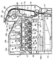
図1は本発明に係る画像形成装置の一形態としてのカラーレーザープリンタの断面図であり、図示のカラーレーザープリンタはタンデム型であって、その本体100内の中央部には、マゼンタ画像形成ユニット1M、シアン画像形成ユニット1C、イエロー画像形成ユニット1Y及びブラック画像形成ユニット1Kが一定の間隔でタンデムに配置されている。
[Image forming apparatus]
FIG. 1 is a cross-sectional view of a color laser printer as an embodiment of an image forming apparatus according to the present invention. The illustrated color laser printer is a tandem type, and a magenta image forming unit is provided at the center of the
上記各画像形成ユニット1M,1C,1Y,1Kには、感光ドラム2a,2b,2c,2dがそれぞれ配置されており、各感光ドラム2a〜2dの周囲には、帯電ローラ3a,3b,3c,3d、現像装置4a,4b,4c,4d、転写ローラ5a,5b,5c,5d及びドラムクリーニング装置6a,6b,6c,6dがそれぞれ配置されている。
Each of the
ここで、前記感光ドラム2a〜2dは、ドラム状の感光体であって、可変速の不図示のステッピングモータによって図示矢印方向(時計方向)に所定のプロセススピードで回転駆動される。又、前記帯電ローラ3a〜3dは、不図示の帯電バイアス電源から印加される帯電バイアスによって感光ドラム2a〜2dの表面を所定の電位に均一に帯電させるものである。
Here, the
更に、前記現像装置4a〜4dは、マゼンタ(M)トナー、シアン(C)トナー、イエロー(Y)トナー、ブラック(K)トナーをそれぞれ収容しており、各感光ドラム2a〜2d上に形成された各静電潜像に各色のトナーを付着させて各静電潜像を各色のトナー像として可視像化するものである。
Further, the developing
又、前記転写ローラ5a〜5dは、各一次転写部にて中間転写ベルト7を介して各感光ドラム2a〜2dに当接可能に配置されている。ここで、中間転写ベルト7は、二次転写対向ローラ8とテンションローラ9との間に張設されて各感光ドラム2a〜2dの上面側に走行可能に配置されており、前記二次転写対向ローラ8は、二次転写部において中間転写ベルト7を介して二次転写ローラ10に当接可能に配置されている。又、テンションローラ9の近傍にはベルトクリーニング装置11が設けられている。
The
ところで、装置本体100内の各画像形成ユニット1M,1C,1Y,1Kの上方には、前記各現像装置4a〜4dにトナーを補給するためのトナーコンテナ12a,12b,12c,12dが一列に並設されている。
Incidentally,
又、装置本体100内の各画像形成ユニット1M,1C,1Y,1Kの下方にはレーザースキャナユニット(LSU)13が配置され、その下方の本体100の底部には給紙カセット14が着脱可能に設置されている。そして、給紙カセット14には複数枚の不図示の用紙が積層収容されており、この給紙カセット14の近傍には、給紙カセット14から用紙を1枚ずつ取り出すピックアップローラ15と、取り出された用紙を搬送パスLへと送り出すフィードローラ16とリタードローラ17が設けられている。
In addition, a laser scanner unit (LSU) 13 is disposed below the
又、装置本体100の側部を上下方向に延びる前記搬送パスLには、用紙を搬送する搬送ローラ対18と、用紙を一時待機させた後に所定のタイミングで前記二次転写対向ローラ8と二次転写ローラ10との当接部である二次転写部へと供給するレジストローラ対19が設けられている。尚、搬送パスLの横には、用紙の両面に画像を形成する場合に使用される別の搬送パスL’が形成されており、この搬送パスL’には複数の搬送ローラ対20が適当な間隔で設けられている。
In addition, the conveyance path L extending in the vertical direction on the side of the apparatus
ところで、装置本体100内の一側部に縦方向に配置された前記搬送パスLは、装置本体100の上面に設けられた排紙トレイ21まで延びており、その途中には定着装置22と排紙ローラ対23が設けられている。
By the way, the conveyance path L arranged in the vertical direction on one side in the apparatus
次に、以上の構成を有するカラーレーザープリンタによる画像形成動作を図1に基づいて説明する。 Next, an image forming operation by the color laser printer having the above configuration will be described with reference to FIG.
画像形成開始信号が発せられると、各画像形成ユニット1M,1C,1Y,1Kにおいて各感光ドラム2a〜2dが図1の矢印方向(時計方向)に所定のプロセススピードで回転駆動され、これらの感光ドラム2a〜2dは、帯電ローラ3a〜3dによって一様に帯電される。又、レーザースキャナユニット13は、各色毎のカラー画像信号によって変調されたレーザー光を出射し、そのレーザー光を各感光ドラム2a〜2dの表面に照射し、各感光ドラム2a〜2d上に各色のカラー画像信号に対応した静電潜像をそれぞれ形成する。
When an image formation start signal is issued, the
そして、先ず、マゼンタ画像形成ユニット1Mの感光ドラム2a上に形成された静電潜像に、該感光ドラム2aの帯電極性と同極性の現像バイアスが印加された現像装置4aによってマゼンタトナーを付着させ、該静電潜像をマゼンタトナー像として可視像化する。このマゼンタトナー像は、感光ドラム2aと転写ローラ5aとの間の一次転写部(転写ニップ部)において、トナーと逆極性の一次転写バイアスが印加された転写ローラ5aの作用によって、図1の矢印方向に回転駆動されている中間転写ベルト7上に一次転写される。
First, magenta toner is attached to the electrostatic latent image formed on the
上述のようにしてマゼンタトナー像が一次転写された中間転写ベルト7は、次のシアン画像形成ユニット1Cへと移動する。そして、シアン画像形成ユニット1Cにおいても、前記と同様にして、感光ドラム2b上に形成されたシアントナー像が一次転写部において中間転写ベルト7上のマゼンタトナー像に重ねて転写される。
The intermediate transfer belt 7 on which the magenta toner image has been primarily transferred as described above moves to the next cyan image forming unit 1C. In the cyan image forming unit 1C as well, the cyan toner image formed on the
以下同様にして、中間転写ベルト7上に重畳転写されたマゼンタ及びシアントナー像の上に、イエロー及びブラック画像形成ユニット1Y,1Kの各感光ドラム2c,2d上にそれぞれ形成されたイエロー及びブラックトナー像が各一次転写部において順次重ね合わせられ、中間転写ベルト7上にはフルカラーのトナー像が形成される。尚、中間転写ベルト7上に転写されないで各感光ドラム2a〜2d上に残留する転写残トナーは、各ドラムクリーニング装置6a〜6dによって除去され、各感光ドラム2a〜2dは次の画像形成に備えられる。
Similarly, yellow and black toners respectively formed on the
そして、中間転写ベルト7上のフルカラートナー像の先端が二次転写対向ローラ8と二次転写ローラ10間の二次転写部(転写ニップ部)に達するタイミングに合わせて、給紙カセット14からピックアップローラ15とフィードローラ16及びリタードローラ17によって搬送パスLへと送り出された用紙がレジストローラ対19によって二次転写部へと搬送される。そして、二次転写部に搬送された用紙に、トナーと逆極性の二次転写バイアスが印加された二次転写ローラ10によってフルカラーのトナー像が中間転写ベルト7から一括して二次転写される。
Then, the pickup from the
而して、フルカラーのトナー像が転写された用紙は、定着装置22へと搬送され、フルカラーのトナー像が加熱及び加圧されて用紙の表面に熱定着され、トナー像が定着された用紙は、排紙ローラ対23によって排紙トレイ21上に排出されて一連の画像形成動作が完了する。尚、用紙上に転写されないで中間転写ベルト7上に残留する転写残トナーは、前記ベルトクリーニング装置11によって除去され、中間転写ベルト7は次の画像形成に備えられる。
Thus, the sheet on which the full-color toner image has been transferred is conveyed to the fixing device 22, and the sheet on which the full-color toner image has been fixed by being heated and pressurized and thermally fixed on the surface of the sheet. The paper is discharged onto the
[給紙カセット]
次に、本発明に係る前記給紙カセット14の詳細を図2〜図7に基づいて説明する。
[Paper cassette]
Next, details of the
図2は本発明に係る給紙カセットの斜視図、図3は同給紙カセットの底板の斜視図、図4は図3のA部拡大詳細図、図5はサイドカーソルが最大幅まで広げられた状態で底板の外れが防がれている状態を示す部分斜視図、図6はサイドカーソルが最小幅に縮小された状態で底板の外れが防がれている状態を示す部分斜視図、図7はサイドカーソルと底板の側面図である。 2 is a perspective view of the paper feed cassette according to the present invention, FIG. 3 is a perspective view of the bottom plate of the paper feed cassette, FIG. 4 is an enlarged detail view of part A of FIG. 3, and FIG. FIG. 6 is a partial perspective view showing a state in which the bottom plate is prevented from coming off in a state where the side cursor is reduced to the minimum width. 7 is a side view of the side cursor and the bottom plate.
図2に示すように、給紙カセット14は、上面が開放された偏平な矩形ボックス状のベースカセット24を有しており、その内部には、支点25を中心として上下に揺動する底板26と、該底板26上に積載された複数枚の用紙の左右を揃える左右一対のサイドカーソル27と、用紙の後端を揃えるエンドカーソル28と、前記底板26を押し上げる不図示のリフト板と、該リフト板を駆動して前記底板26を押し上げるリフト機構29等が設けられている。ここで、リフト機構29は、ベースカセット24の右側に設けられており、被動ギヤ30と該被動ギヤ30に噛合する扇形ギヤ(不図示)を含んで構成されている。尚、図示しないが、扇形ギヤは前記リフト板を支持するリフト軸に結着されている。
As shown in FIG. 2, the
而して、給紙カセット14は、画像形成装置本体100に対して用紙搬送方向(図2の矢印方向)に着脱されるものであって、図示しないが、装置本体100側には、板金製の本体フレームによって構成される矩形凹状のカセット装着部が形成されており、このカセット装着部に対して給紙カセット14が用紙搬送方向に着脱される。
Thus, the
ところで、図3に示すように、平面視H状に成形されており、その支点とは反対側の左右両端には係合爪26aが形成され、その内側には係合段部26bが幅方向に沿って形成されている(詳細は図4参照)。
By the way, as shown in FIG. 3, it is formed in an H shape in a plan view. Engaging
他方、図7に示すように、左右一対の前記サイドカーソル27の手前側の端面(図7の左端面)27aは底板26の回動支点25を中心とする円弧状とされており、その端面27aの上部には外側方に向かって直角に折り曲げられた係合突起27bが形成されている(図5及び図6参照)。
On the other hand, as shown in FIG. 7, the front end surfaces (left end surfaces in FIG. 7) 27a of the pair of left and
以上の構成を有する給紙カセット14を装置本体100側のカセット装着部に装着すると、該給紙カセット14のリフト機構29の一部を構成する被動ギヤ30が装置本体100側の不図示の駆動ギヤに噛合する。そして、画像形成動作によって給紙カセット14の底板26上に積載された用紙が消費されると、装置本体100側に設けられた不図示の駆動モータからの駆動力が駆動ギヤを経て給紙カセット14側の被動ギヤ30に伝達され、該被動ギヤ30とこれに噛合する不図示の扇形ギヤ及びリフト駆動軸が回転駆動される。すると、不図示のリフト板が駆動され、該リフト板が底板26を回動支点25を中心として上方へ揺動させて押し上げるため、該底板26上に積載された用紙が図1に示すピックアップローラ15に押し当てられ、この結果、連続した給紙が可能となる。
When the
そして、画像形成動作によって給紙カセット14内の用紙が無くなるか或は残り少なくなると、給紙カセット14が装置本体100から引き出され、該給紙カセット14内の底板26上に用紙が積載されて補給されるが、このとき、ユーザーは、左右のサイドカーソル27によって用紙の左右を揃え、エンドカーソル28によって用紙の前後を揃える。
When there is no more or less paper in the
而して、給紙カセット14の底板26上に最大サイズの用紙を収容したために左右のサイドカーソル27が図5に示すように最大幅まで広がった状態において、底板26が最上昇位置までリフトアップされた場合には、サイドカーソル27に形成された係合突起27bが底板26の係合段部26bに係合するため、底板26のサイドカーソル27からの外れが確実に防がれる。そして、サイドカーソル27が最大幅まで広がった時点で底板26の左右両端に形成された係合爪26aが該サイドカーソル27に係合してサイドカーソル27の最大幅以上の移動を規制するため、該サイドカーソル27に形成された係合突起27bによって底板26の最上昇位置が規制され、該底板26のサイドカーソル27からの外れが常に確実に防がれる。
Thus, since the maximum size paper is accommodated on the
又、図6に示すように、給紙カセット14の底板26上に最小サイズの用紙を収容したために左右のサイドカーソル27が図6に示すように最小幅まで縮小した状態において、底板26が最上昇位置までリフトアップされた場合においても、サイドカーソル27に形成された係合突起27bが底板26の係合段部26bに係合するため、底板26のサイドカーソル27からの外れが確実に防がれる。
Further, as shown in FIG. 6, since the left and
更に、本実施の形態では、図7に示すように各サイドカーソル27の手前側の端面27aを底板26の回動支点25を中心とする円弧状としたため、底板26がどの高さ位置にあっても該底板26に形成された係合爪26aがサイドカーソル27に常に係合することとなり、従って、サイドカーソル26の最大幅以上の移動が底板26の係合爪26aによって規制される。このため、サイドカーソル27に形成された係合突起27bによって底板26のサイドカーソル27からの外れが常に確実に防がれる。
Furthermore, in the present embodiment, as shown in FIG. 7, the
以上のように、本発明に係る給紙カセット14によれば、底板26のサイドカーソル27からの抜けが防がれるため、該給紙カセット14から用紙を安定的に給送して該用紙に画像を形成することができる。
As described above, according to the
尚、以上は本発明をカラーレーザープリンタとこれに着脱される給紙カセットに適用した形態について説明したが、本発明は、単色のモノクロ画像形成装置とこれに着脱される給紙カセットに対しても同様に適用可能であり、更にプリンタ以外の複写機やファクシミリ装置等に対しても適用可能である。 In the above description, the present invention is applied to a color laser printer and a paper cassette attached to and detached from the color laser printer. However, the present invention is applied to a monochrome monochrome image forming apparatus and a paper cassette attached to and detached from it. Is also applicable to a copying machine other than a printer, a facsimile machine, and the like.
1M マゼンタ画像形成ユニット
1C シアン画像形成ユニット
1Y イエロー画像形成ユニット
1K ブラック画像形成ユニット
2a〜2d 感光ドラム
3a〜3d 帯電ローラ
4a〜4d 現像装置
5a〜5d 転写ローラ
6a〜6d ドラムクリーニング装置
7 中間転写ベルト
8 二次転写対向ローラ
9 テンションローラ
10 二次転写ローラ
11 ベルトクリーニング装置
12a〜12d トナーコンテナ
13 レーザースキャナユニット(LSU)
14 給紙カセット
15 ピックアップローラ
16 フィードローラ
17 リタードローラ
18 搬送ローラ対
19 レジストローラ対
20 搬送ローラ対
21 排紙トレイ
22 定着装置
23 排紙ローラ対
24 ベースカセット
25 底板の支点
26 底板
26a 底板の係合爪
26b 底板の係合段部
27 サイドカーソル
27a サイドカーソルの端面
27b サイドカーソルの係合突起
28 エンドカーソル
29 リフト機構
30 被動ギヤ
100 画像形成装置本体
L,L’ 搬送パス
1M Magenta image forming unit 1C Cyan
Claims (4)
前記各サイドカーソルに前記底板の最上昇時に該底板に係合する係合突起を形成するとともに、前記底板の左右両端に前記サイドカーソルの最大幅以上の移動を規制する係合爪を形成したことを特徴とする給紙カセット。 In a paper feed cassette comprising a bottom plate that is attachable to and detachable from the image forming apparatus main body and that can swing up and down, and a pair of left and right side cursors that regulate the width direction of the paper stacked on the bottom plate.
Each side cursor is formed with an engaging projection that engages with the bottom plate when the bottom plate is fully raised, and an engaging claw that restricts the movement of the side cursor over the maximum width is formed at the left and right ends of the bottom plate. A paper cassette characterized by
An image forming apparatus comprising: a sheet feeding cassette according to claim 1 detachably attached to a main body.
Priority Applications (1)
| Application Number | Priority Date | Filing Date | Title |
|---|---|---|---|
| JP2007319185A JP4988532B2 (en) | 2007-12-11 | 2007-12-11 | Sheet cassette and image forming apparatus having the same |
Applications Claiming Priority (1)
| Application Number | Priority Date | Filing Date | Title |
|---|---|---|---|
| JP2007319185A JP4988532B2 (en) | 2007-12-11 | 2007-12-11 | Sheet cassette and image forming apparatus having the same |
Related Child Applications (1)
| Application Number | Title | Priority Date | Filing Date |
|---|---|---|---|
| JP2012100517A Division JP2012162400A (en) | 2012-04-26 | 2012-04-26 | Paper loading device and image forming apparatus equipped with the same |
Publications (2)
| Publication Number | Publication Date |
|---|---|
| JP2009137757A JP2009137757A (en) | 2009-06-25 |
| JP4988532B2 true JP4988532B2 (en) | 2012-08-01 |
Family
ID=40868792
Family Applications (1)
| Application Number | Title | Priority Date | Filing Date |
|---|---|---|---|
| JP2007319185A Expired - Fee Related JP4988532B2 (en) | 2007-12-11 | 2007-12-11 | Sheet cassette and image forming apparatus having the same |
Country Status (1)
| Country | Link |
|---|---|
| JP (1) | JP4988532B2 (en) |
Families Citing this family (1)
| Publication number | Priority date | Publication date | Assignee | Title |
|---|---|---|---|---|
| CN106183462B (en) * | 2016-08-31 | 2019-05-14 | 重庆品胜科技有限公司 | A kind of printer |
Family Cites Families (3)
| Publication number | Priority date | Publication date | Assignee | Title |
|---|---|---|---|---|
| JPH06227680A (en) * | 1993-01-29 | 1994-08-16 | Ricoh Co Ltd | Sheet storage container |
| JP4315031B2 (en) * | 2004-03-19 | 2009-08-19 | 富士ゼロックス株式会社 | Paper cassette |
| JP2007217153A (en) * | 2006-02-17 | 2007-08-30 | Fuji Xerox Co Ltd | Image forming device |
-
2007
- 2007-12-11 JP JP2007319185A patent/JP4988532B2/en not_active Expired - Fee Related
Also Published As
| Publication number | Publication date |
|---|---|
| JP2009137757A (en) | 2009-06-25 |
Similar Documents
| Publication | Publication Date | Title |
|---|---|---|
| JP5134347B2 (en) | Image forming apparatus | |
| JP2011059510A (en) | Image forming apparatus and tandem type photoreceptor unit | |
| CN102193472A (en) | Process cartridge and imaging device | |
| JP5793966B2 (en) | Image forming apparatus and process unit | |
| JP5482215B2 (en) | Image forming apparatus | |
| JP2008003496A (en) | Image forming apparatus | |
| JP5139818B2 (en) | Developing device and image forming apparatus having the same | |
| JP4988532B2 (en) | Sheet cassette and image forming apparatus having the same | |
| JP5080932B2 (en) | Manual sheet feeder and image forming apparatus having the same | |
| JP4944748B2 (en) | Sheet cassette and image forming apparatus having the same | |
| JP2009145633A (en) | Drum unit and image forming apparatus including the same | |
| JP2012162400A (en) | Paper loading device and image forming apparatus equipped with the same | |
| JP5743163B2 (en) | GEAR DEVICE, DRIVE DEVICE, AND ELECTRONIC DEVICE | |
| JP5149594B2 (en) | Toner replenishing device and image forming apparatus having the same | |
| JP5144233B2 (en) | Image forming apparatus | |
| JP2005077498A (en) | Image forming apparatus | |
| JP2009058918A (en) | Color image forming apparatus | |
| JP2007226007A (en) | Image forming apparatus, image-formation unit, and method for assembling image forming apparatus | |
| JP2013011708A (en) | Image forming apparatus | |
| JP4996442B2 (en) | Image forming apparatus | |
| KR100837675B1 (en) | Image forming apparatus | |
| JP2009137701A (en) | Paper feeding cassette and image forming device with paper feeding cassette | |
| JP5104977B2 (en) | Image forming apparatus and developing unit used in the image forming apparatus | |
| JP5015817B2 (en) | Image forming apparatus | |
| JP2010002622A (en) | Image forming apparatus |
Legal Events
| Date | Code | Title | Description |
|---|---|---|---|
| A621 | Written request for application examination |
Free format text: JAPANESE INTERMEDIATE CODE: A621 Effective date: 20101021 |
|
| A977 | Report on retrieval |
Free format text: JAPANESE INTERMEDIATE CODE: A971007 Effective date: 20120316 |
|
| TRDD | Decision of grant or rejection written | ||
| A01 | Written decision to grant a patent or to grant a registration (utility model) |
Free format text: JAPANESE INTERMEDIATE CODE: A01 Effective date: 20120328 |
|
| A01 | Written decision to grant a patent or to grant a registration (utility model) |
Free format text: JAPANESE INTERMEDIATE CODE: A01 |
|
| A61 | First payment of annual fees (during grant procedure) |
Free format text: JAPANESE INTERMEDIATE CODE: A61 Effective date: 20120426 |
|
| R150 | Certificate of patent or registration of utility model |
Free format text: JAPANESE INTERMEDIATE CODE: R150 Ref document number: 4988532 Country of ref document: JP Free format text: JAPANESE INTERMEDIATE CODE: R150 |
|
| FPAY | Renewal fee payment (event date is renewal date of database) |
Free format text: PAYMENT UNTIL: 20150511 Year of fee payment: 3 |
|
| LAPS | Cancellation because of no payment of annual fees |