JP4987595B2 - Solid ink stick with reliable encoding data - Google Patents
Solid ink stick with reliable encoding data Download PDFInfo
- Publication number
- JP4987595B2 JP4987595B2 JP2007177296A JP2007177296A JP4987595B2 JP 4987595 B2 JP4987595 B2 JP 4987595B2 JP 2007177296 A JP2007177296 A JP 2007177296A JP 2007177296 A JP2007177296 A JP 2007177296A JP 4987595 B2 JP4987595 B2 JP 4987595B2
- Authority
- JP
- Japan
- Prior art keywords
- code element
- ink
- ink stick
- pattern
- code
- Prior art date
- Legal status (The legal status is an assumption and is not a legal conclusion. Google has not performed a legal analysis and makes no representation as to the accuracy of the status listed.)
- Expired - Fee Related
Links
- 239000007787 solid Substances 0.000 title description 18
- 230000008859 change Effects 0.000 description 12
- 239000012071 phase Substances 0.000 description 12
- 239000000155 melt Substances 0.000 description 10
- 238000003780 insertion Methods 0.000 description 7
- 230000037431 insertion Effects 0.000 description 7
- 230000003287 optical effect Effects 0.000 description 7
- 239000007788 liquid Substances 0.000 description 5
- 230000007246 mechanism Effects 0.000 description 5
- 238000000034 method Methods 0.000 description 5
- 230000009977 dual effect Effects 0.000 description 4
- 238000003384 imaging method Methods 0.000 description 4
- 238000002844 melting Methods 0.000 description 4
- 230000008018 melting Effects 0.000 description 4
- 238000013459 approach Methods 0.000 description 2
- 239000003086 colorant Substances 0.000 description 2
- 230000007547 defect Effects 0.000 description 2
- 238000001514 detection method Methods 0.000 description 2
- 238000005516 engineering process Methods 0.000 description 2
- 230000005484 gravity Effects 0.000 description 2
- 238000007641 inkjet printing Methods 0.000 description 2
- 239000007791 liquid phase Substances 0.000 description 2
- 239000003550 marker Substances 0.000 description 2
- 239000000463 material Substances 0.000 description 2
- 238000012986 modification Methods 0.000 description 2
- 230000004048 modification Effects 0.000 description 2
- 239000008188 pellet Substances 0.000 description 2
- 238000007639 printing Methods 0.000 description 2
- 239000004065 semiconductor Substances 0.000 description 2
- 239000007790 solid phase Substances 0.000 description 2
- 230000007704 transition Effects 0.000 description 2
- 230000003466 anti-cipated effect Effects 0.000 description 1
- 238000003491 array Methods 0.000 description 1
- 230000008901 benefit Effects 0.000 description 1
- 238000005266 casting Methods 0.000 description 1
- 238000000748 compression moulding Methods 0.000 description 1
- 239000000975 dye Substances 0.000 description 1
- 238000001746 injection moulding Methods 0.000 description 1
- 238000002372 labelling Methods 0.000 description 1
- 230000007257 malfunction Effects 0.000 description 1
- 238000004519 manufacturing process Methods 0.000 description 1
- 239000000203 mixture Substances 0.000 description 1
- 238000004806 packaging method and process Methods 0.000 description 1
- 230000003252 repetitive effect Effects 0.000 description 1
- 238000012795 verification Methods 0.000 description 1
- 230000000007 visual effect Effects 0.000 description 1
Images


Classifications
-
- B—PERFORMING OPERATIONS; TRANSPORTING
- B41—PRINTING; LINING MACHINES; TYPEWRITERS; STAMPS
- B41J—TYPEWRITERS; SELECTIVE PRINTING MECHANISMS, i.e. MECHANISMS PRINTING OTHERWISE THAN FROM A FORME; CORRECTION OF TYPOGRAPHICAL ERRORS
- B41J2/00—Typewriters or selective printing mechanisms characterised by the printing or marking process for which they are designed
- B41J2/005—Typewriters or selective printing mechanisms characterised by the printing or marking process for which they are designed characterised by bringing liquid or particles selectively into contact with a printing material
- B41J2/01—Ink jet
- B41J2/17—Ink jet characterised by ink handling
- B41J2/175—Ink supply systems ; Circuit parts therefor
- B41J2/17593—Supplying ink in a solid state
-
- B—PERFORMING OPERATIONS; TRANSPORTING
- B41—PRINTING; LINING MACHINES; TYPEWRITERS; STAMPS
- B41J—TYPEWRITERS; SELECTIVE PRINTING MECHANISMS, i.e. MECHANISMS PRINTING OTHERWISE THAN FROM A FORME; CORRECTION OF TYPOGRAPHICAL ERRORS
- B41J2/00—Typewriters or selective printing mechanisms characterised by the printing or marking process for which they are designed
- B41J2/005—Typewriters or selective printing mechanisms characterised by the printing or marking process for which they are designed characterised by bringing liquid or particles selectively into contact with a printing material
- B41J2/01—Ink jet
- B41J2/17—Ink jet characterised by ink handling
- B41J2/175—Ink supply systems ; Circuit parts therefor
Description
本開示は、相変化インクジェットプリンタで用いられる固形(ソリッド)インクスティックに関する。 The present disclosure relates to solid ink sticks used in phase change ink jet printers.
固形インク又は相変化(固相から液相への変化)のインクプリンタは、通常、ペレット又はインクスティックのいずれかで、固形状態のインクを受け取る。固形インクのペレット又はインクスティックは、インクのローダ(収容し保持する装置、部材又は部分)の供給シュートに配置され、インクローダにおける供給機構は、固形インクをヒータ組立体に送給する。固形インクスティックは、供給シュートを通してヒータ組立体におけるヒータプレートの方向に、重力により供給されるか又はばねにより付勢される。ヒータプレートは、プレートに衝突する固形インクを溶融して液体にし、その液体は、記録媒体上に噴射するためにプリントヘッドに送給される。 Solid ink or phase change (solid phase to liquid phase) ink printers typically receive solid state ink in either pellets or ink sticks. The solid ink pellets or ink sticks are arranged in a supply chute of an ink loader (accommodating and holding device, member or part), and a supply mechanism in the ink loader delivers solid ink to the heater assembly. The solid ink stick is fed by gravity or biased by a spring through a feed chute in the direction of the heater plate in the heater assembly. The heater plate melts solid ink impinging on the plate into a liquid, and the liquid is fed to the print head for jetting onto the recording medium.
固形インク技術において直面する1つの問題は、インクスティックの正しい搭載及び使用される画像形成装置との両立性を保証するためのインクスティックの区別及び識別である。供給チャネルにおける間違った色のインクスティック、異なる固形インクプリンタ向けのインクスティック、不適格インクの使用等は、画質に影響を与え、又はさらに、固形インク画像形成装置を損傷する可能性がある。以前から知られる相変化インクシステムにおいては、インクスティックの区別及び識別は、キー溝形状の特徴をインクスティックの外面に形成することにより成されていた。これらの特徴は、不適切に構成されたインクスティックが、プリンタの供給チャネルに挿入されないようにする働きがあった。 One problem faced in solid ink technology is the distinction and identification of ink sticks to ensure correct mounting of the ink sticks and compatibility with the image forming apparatus used. Incorrectly colored ink sticks in the supply channel, ink sticks for different solid ink printers, use of unqualified ink, etc. can affect image quality or even damage the solid ink imaging device. In previously known phase change ink systems, the distinction and identification of ink sticks has been made by forming keyway-shaped features on the outer surface of the ink stick. These features served to prevent improperly configured ink sticks from being inserted into the printer supply channel.
種々の価格及びカラーテーブルの好みをもつ世界市場は、市場において、多数のインクの種類が、ほぼ同一の大きさ/特徴のインク及び/又はインクパッケージと同時に存在することがある状況を生成した。従って、インクスティックはほぼ同じように見えるが、実際は、例えば市場の価格付け又はカラーテーブルといった要因のために、異なる相変化印刷システムに向けられたものであることがある。広範囲の可能なインクスティック構成、市場戦略、価格付け等のために、適切なインクだけがプリンタにより受け入れられるようにインクスティックを区別することは、物理的キー溝形状等を超える識別方法を必要とする。 The global market with varying prices and color table preferences has created a situation in which a large number of ink types may be present at the same time as approximately the same size / feature ink and / or ink package. Thus, while ink sticks look similar, in practice they may be directed to different phase change printing systems due to factors such as market pricing or color tables. For a wide range of possible ink stick configurations, market strategies, pricing, etc., distinguishing ink sticks so that only the appropriate ink is accepted by the printer requires an identification method that goes beyond physical keyway shapes, etc. To do.
固形インク技術の性質は、通常のラベル付け又はタグ付け機構を追加するとインクスティックを実用的でないものにする。タグ及びラベルは、インクスティックが溶融する前に除去されなければならない。或いは別の場合には、タグ又はラベル材料が液体インク成分を詰まらせてしまう。プリンタ制御システムによりインクスティックの識別に役立つよう実施される1つの方法は、インクスティックの外面に、インクローダのセンサと対話するエンコード特徴を組み込むことである。インクスティックに特有の情報に対応する信号又はコード化信号パターンを生成するように、これらの特徴をインクローダにおける1つ又はそれ以上のセンサと対話するように構成することにより、インクスティックデータをこれらの特徴にエンコードすることができる。インクスティック本体の、軟らかく、ろう状の性質のために、インクスティックの外面に形成される特徴は、容易に損傷されることがあり、その結果、エンコードデータが失われる可能性がある。従って、損傷を処理するため及びインクローダのセンサ・システムによる正確な読み取りを保証するために、エンコード特徴は、通常、影響を受けにくいように大きいものであった。大きい特徴は、インクスティックに組み込むことができる情報量を制限する。しかし、インクスティックにより多くの情報を組み込むことを可能にする小さいエンコード特徴の使用は、軟らかいインク材料の脆弱性のために、情報の破損、及び不正確な検知又は読み取りの可能性を増大させる。 The nature of solid ink technology makes ink sticks impractical with the addition of conventional labeling or tagging mechanisms. Tags and labels must be removed before the ink stick melts. Alternatively, the tag or label material can clog the liquid ink component. One method implemented by the printer control system to help identify ink sticks is to incorporate an encoding feature on the outer surface of the ink stick that interacts with ink loader sensors. By configuring these features to interact with one or more sensors in the ink loader to generate a signal or coded signal pattern that corresponds to information specific to the ink stick, the ink stick data can be Can be encoded into the features. Due to the soft, waxy nature of the ink stick body, features formed on the outer surface of the ink stick can be easily damaged, resulting in loss of encoded data. Thus, to handle damage and to ensure accurate reading by the ink loader sensor system, the encoding features were usually large enough to be unaffected. The large feature limits the amount of information that can be incorporated into the ink stick. However, the use of small encoding features that allow more information to be incorporated into the ink stick increases the possibility of information corruption and inaccurate detection or reading due to the vulnerability of the soft ink material.
ラベル又はタグを必要とせずに、インクスティック・データをインクスティック内により良好に保存するインクスティックが以下に説明される。インクスティックは、画像形成装置のインクローダ内に適合するように構成されたインクスティック本体を含む。少なくとも1つのコード化センサ特徴が、インクスティック本体の外面に形成される。少なくとも1つのコード化センサ特徴は、複数のコード要素パターンを含む。複数のコード要素パターンの各々のコード要素パターンは、インクローダにおける少なくとも1つのセンサを作動させて、同じコード化信号パターンを生成するように構成される。コード要素パターンは、完全な又は部分的な繰り返しコード情報を含むため、コード要素構成の検証は、1つのパターンを別のパターンと比較することにより行われる。従って、意図的でない暗号化をもたらすことがある欠陥及び重大な不具合は除外できるため、コード要素内に含まれる情報は確実に解釈される。繰り返しパターン内における非繰り返しコード要素が冗長情報を増加させるのに用いられてもよく、例えば、インクリメントに増す数値が、コード要素の読み取りの進行を追跡するように作用し、又は1つのスティックの次のスティックへの遷移を解釈するように作用するようにしてもよい。1つのスティックと別の物と間の区別もまた、一次パターンから独立して読み取られる付加コード又はセンサ要素を用いて実現することができる。この要素又は要素パターンは、一次パターンの前、後ろ若しくはこれに隣接して配置してもよいし、又は、スティックの別の表面に配置してもよい。 Ink sticks that better store ink stick data in ink sticks without the need for labels or tags are described below. The ink stick includes an ink stick body configured to fit within an ink loader of the image forming apparatus. At least one coded sensor feature is formed on the outer surface of the ink stick body. At least one encoded sensor feature includes a plurality of code element patterns. Each code element pattern of the plurality of code element patterns is configured to activate at least one sensor in the ink loader to generate the same encoded signal pattern. Since code element patterns include complete or partial repetitive code information, verification of code element configuration is performed by comparing one pattern with another pattern. Thus, the information contained within the code element is reliably interpreted, since defects and serious malfunctions that can result in unintentional encryption can be excluded. Non-repeating code elements within a repeating pattern may be used to increase redundant information, for example, a numerical value that increments acts to track the progress of reading code elements, or follows one stick It is also possible to act to interpret the transition to a stick. The distinction between one stick and another can also be achieved using additional codes or sensor elements that are read independently of the primary pattern. This element or element pattern may be placed in front of, behind, or adjacent to the primary pattern, or on another surface of the stick.
別の実施形態では、インクスティックを相変化(固相から液相に変化させる)画像形成装置のインクローダに供給する方法が提供される。この方法は、少なくとも1つのインクスティックを、相変化画像形成装置のインクローダに挿入することを含む。少なくとも1つのインクスティックは、複数のコード要素パターンを含む少なくとも1つのコード化センサ特徴を含む。複数のコード要素パターンの各々は、同じコード化信号パターンを生成するように構成される。少なくとも1つのインクスティックは次いで、溶融装置に向けて付勢される。インクスティックが供給チャネルに沿って付勢されるとき、少なくとも1つのセンサが、複数のコード化信号パターンを生成するように、複数のコード要素パターンにより作動される。次いで、複数のコード化信号パターンが比較されて、コード化センサ特徴にエンコードされたコードワード(語)を求める。同様のインクローダ構成では、インクのコード化信号パターンは、センサ・ビーム又は他の検知素子を移動させることにより、定位置にあるインクを用いて読み取る又は検知することができる。 In another embodiment, a method is provided for feeding an ink stick to a phase change (changing from a solid phase to a liquid phase) image forming device ink loader. The method includes inserting at least one ink stick into an ink loader of a phase change image forming apparatus. The at least one ink stick includes at least one encoded sensor feature that includes a plurality of code element patterns. Each of the plurality of code element patterns is configured to generate the same encoded signal pattern. The at least one ink stick is then biased towards the melting device. When the ink stick is energized along the supply channel, at least one sensor is activated by the plurality of code element patterns to generate a plurality of encoded signal patterns. The plurality of coded signal patterns are then compared to determine a code word (word) encoded in the coded sensor feature. In a similar ink loader configuration, the ink coded signal pattern can be read or detected using the ink in place by moving the sensor beam or other sensing element.
更に別の実施形態では、相変化画像形成装置のためのシステムが提供される。このシステムは、インクスティック本体の外面に形成される少なくとも1つのコード化センサ特徴を含む。少なくとも1つのコード化センサ特徴は、複数のコード要素パターンを含む。複数のコード要素パターンの各々のコード要素パターンは、供給チャネルにおける少なくとも1つのセンサを作動させて、同じコード化信号パターンを生成するように構成される。このシステムは、複数のコード要素パターンの各々のコード要素パターンにより作動されて、センサ・システムの作動に対応する複数のコード化信号パターンを生成するように、相変化画像形成装置のインクローダ内に又はこれに関連されたセンサ・システムを含む。このシステムは、さらに、複数のコード化信号パターンを受信し、複数のコード化信号パターンを比較して、コード化センサ特徴にエンコードされたコードワードを求めるコントローラを含む。 In yet another embodiment, a system for a phase change imaging device is provided. The system includes at least one coded sensor feature formed on the outer surface of the ink stick body. At least one encoded sensor feature includes a plurality of code element patterns. Each code element pattern of the plurality of code element patterns is configured to activate at least one sensor in the supply channel to generate the same encoded signal pattern. The system is implemented in the ink loader of the phase change imaging device to be activated by each code element pattern of the plurality of code element patterns to generate a plurality of encoded signal patterns corresponding to the operation of the sensor system. Or a sensor system associated therewith. The system further includes a controller that receives the plurality of encoded signal patterns and compares the plurality of encoded signal patterns to determine a codeword encoded in the encoded sensor feature.
本発明の実施形態の一般的な理解のために、図面を参照する。図面では、全体にわたり同じ符号が同じ要素を示すのに用いられる。 For a general understanding of embodiments of the present invention, reference is made to the drawings. In the drawings, like reference numerals are used throughout to designate like elements.
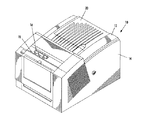
図1は、上面12及び側面14を有する外側ハウジングを含む、固形インクすなわち相変化インクを用いるプリンタ10を示す。フロントパネル表示画面16のようなユーザ・インターフェースは、プリンタのステータスに関する情報及びユーザ命令を表示する。プリンタの動作を制御するためのボタン18又はその他の制御要素は、フロントパネル表示画面に隣接しているか、又はプリンタの他の位置にあってもよい。インクジェット印刷機構(図示せず)は、ハウジングの内側に収容される。インクローダは、インクをその印刷機構に送給する。インクローダは、プリンタハウジング上面の下方に収容される。オペレータがインクローダにアクセスできるように、ハウジングの上面は、図2に示されるように開くヒンジ取り付けされたインク・アクセス・カバー20を含む。
FIG. 1 shows a
図2は、インク・アクセス・カバー20を持ち上げて、インク支持リンク機構要素22及びインクスティック供給装置すなわちインクローダを見せたプリンタ10を示す。図示される特定のプリンタでは、プリンタのインク・アクセス・カバー20は、これが持ち上げられたときに、インク支持リンク機構22が摺動し、インク支持位置にピボット運動するようにインク支持リンク機構要素22に取り付けられている。図2からわかるように、インクローダは、キー付き開口部24を有するキープレート26を含む。各々のキー付キー付き開口部24A、24B、24C、24Dは、インクローダの幾つかの個々の供給チャネル28A、28B、28C、28Dの1つの挿入端にアクセスできるようにする(図3を参照されたい)。
FIG. 2 shows the
インクローダの各々の縦方向供給チャネル28は、1つの特定色のインクスティック30を対応の溶融プレート32に送給する。各々の供給チャネルは、供給チャネルの挿入端から供給チャネルの溶融端への縦方向供給方向を有する。供給チャネルの溶融端は、溶融プレートに隣接する。溶融プレートは、固形インクスティックを液体形態に溶融する。溶融されたインクは、供給チャネルの溶融端と溶融プレートとの間の間隙33を通って、液体インクリザーバ(図示せず)に滴下する。供給チャネル28A、28B、28C、28D(図3を参照)は、挿入端から溶融端への縦方向寸法と、この縦方向寸法に対して実質的に垂直な横方向寸法を有する。
Each longitudinal feed channel 28 of the ink loader feeds one specific
図示される特定の実施形態における各々の供給チャネル28は、縦方向供給チャネルの長さに沿って、各々の供給チャネルの溶融端にある溶融プレート32の方向に、個々のインクスティックを押し付ける定力ばね36のような駆動力又は要素により駆動される押しブロック34を含む。定力ばね36の張力は、押しブロック34を供給チャネルの溶融端に向けて駆動する。インク支持リンク機構22は、押しブロックに装着された定力ばねに取り付けられたヨーク38と結合される。インク支持リンク機構22への取り付けは、インク・アクセス・カバーがキー・プレート26を見せるように持ち上げられたときに、押しブロック34を供給チャネルの挿入端の方向に引っ張る。図示される実施例では、定力ばね36は、面が実質的に垂直軸に沿って配向された薄板ばねとすることができる。
Each supply channel 28 in the particular embodiment shown is a constant force that presses an individual ink stick along the length of the longitudinal supply channel in the direction of the
カラー・プリンタは通常4色のインク(イエロー、シアン、マゼンタ、及び黒色)を使用する。各々の色のインクスティック30は、対応する供給チャネル28A、28B、28C、28Dの個々の1つを通って送給される。プリンタのオペレータは、1つの色のインクスティックを別の色の供給チャネルに挿入しないよう注意する。インクスティックは色の染料が深く染み込んでいることがあるため、プリンタのオペレータが、どの色がどれであるかを視覚的な色だけで区別するのは難しい。シアン、マゼンタ、及び黒色のインクスティックは、特に色の外観に基づいて視覚的に区別するのは困難である可能性がある。正確な色のインクスティックだけが確実に各々の供給チャネルに挿入されるようにプリンタ・オペレータを助けるため、キー・プレート26は、キー付き開口部24A、24B、24C、24Dを有する。キー・プレートの各々のキー付き開口部24A、24B、24C、24Dは、独特な形状を有する。その供給チャネルのための色のインクスティック30は、キー付き開口部の形状に対応する形状を有する。キー付き開口部とこれに対応するインクスティック形状は、その供給チャネルのための正確な色のインクスティック以外のすべての色の各々のインク供給チャネルのインクスティックを除外する。
Color printers typically use four colors of ink (yellow, cyan, magenta, and black). Each
インクローダに使用するための例示的な固形インクスティック30が図4に示される。インクスティックは、3次元のインクスティック本体で形成される。図示されるインクスティック本体は、一般に底面52により例示される底部と、一般に上面54により例示される上部とを有する。図示される特定の底面52及び上面54は、実質的に互いに平行であるが、他の外形及び相対関係を帯びていてもよい。さらに、インクスティック本体の表面は平らである必要はないし、互いに平行又は垂直である必要もない。
An exemplary
インクスティック本体はさらに、側面56及び端面61、62のような複数の側端部を有する。図示される実施形態は、2つの端面61、62と、2つの横方向側面56とを含む4つの側面を含む。横方向側面56の基本要素は、実質的に互いに平行であり、かつ、上面及び底面52、54に対して実質的に垂直である。端面61、62もまた基本的に、実質的に互いに平行であり、かつ、上面及び底面、及び横方向側面に対して実質的に垂直である。端面の一方61は前端面であり、他方の端面62は後端面である。インクスティック本体は、鋳込み成形、射出成形、圧縮成形、又は他の既知の技術によって形成することができる。
The ink stick body further has a plurality of side edges such as a
再び図4を参照すると、インクスティックは、可変の制御情報又は属性情報をインクスティック30にエンコードするための1つ又はそれ以上のコード化センサ特徴(フィーチャ)80を含む。情報をインクスティックの表面にエンコードするために、コード化センサ特徴80は、インクローダのセンサ位置に対応するインクスティックの外面上の所定位置に形成される複数のコード要素パターン84を含む(図5を参照されたい)。各々のコード要素パターンのコード要素86は、コード要素パターンがエンコード化制御情報又は属性情報に対応するコード化信号パターンを生成するように、所定の方法でインクローダの1つ又はそれ以上のセンサを作動させるように構成される。ここに用いられるように、コード要素パターンは、コード化信号パターンを生成するためのコード要素の数、配置、又は構成を含むことができる。
Referring again to FIG. 4, the ink stick includes one or more coded sensor features 80 for encoding variable control information or attribute information into the
各々のコード要素86は、湾曲状、球状、傾斜状、正方形状にでき、更に、フラグ若しくはアクチュエータを移動させることにより、又は、光学検知システムを用いること等により、直接又は間接に、信頼性のあるセンサ作動を可能にするいずれの形状であってもよい。例えば、図5のコード要素は、光源から光検知器上に光を反射するように構成された傾斜表面を有する。代替的には、各々のコード要素は、例えば、深さ、長さ、幅、又は要素間の間隔、又は寸法特徴のいずれかの組み合わせといったコード要素の物理的寸法に基づいて、1つ又はそれ以上のセンサを作動させるように構成することができる。
Each
インクスティック上に配置することができるコード要素パターン84の数と配置とは、インクスティックとセンサ配置の選択による幾何形状によってのみ制限される。1つの実施形態では、コード要素パターンは、1つ又はそれ以上のほぼ線形に並んだコード化要素のアレイを含み、このコード化要素のアレイが、供給方向に対してほぼ平行な経路を形成して、インクスティックが押しブロック又は重力によって供給チャネルに沿って付勢されると読み取られる。しかし、上記のパターンを形成するコード要素は、供給方向に対して垂直のアレイ、同心円等を含む、任意の好適な配置、パターンその他同様なものとすることができる。コード要素パターン84は、例えば、インクスティック外面の凹部又は挿入部分等の、インクスティックの外面の位置に配置できる利点があり、通常のスティックの取り扱いに伴なう損傷がコード要素パターンの完全性を損なうことがなくなる。
The number and placement of
1つの実施形態のいて、コード化センサ特徴80により示される少なくとも1つの独特な識別子すなわちコードワード(語)を選択し、複数のコード化要素がセンサを作動させて、選択されたコードワードに対応するコード化信号パターンを生成するように複数のコード要素を構成又は配置することによって、情報をコード化センサ特徴80にエンコードすることができる。コードワードは、画像形成装置制御システムによる解釈と関連付けることができる1つ又はそれ以上の数値、英数字、記号等を含むことができる。コードワードは、インクスティックに関する制御及び/又は属性情報を示すよう指定することができる。コードワードは、画像形成装置制御システムによって読み取り、制御システムによって多数の方法により使用できる、インクスティックに関する制御及び/又は属性情報に変換することができる。制御システムは、例えばデータベース又はテーブルといったデータ構造内に格納されたデータにアクセスするための検索キーとして、コードワードを使用することができる。データ構造に格納されたデータは、各々のコードワードに対応する情報と関連する複数の可能コードワードを含むことができる。
In one embodiment, select at least one unique identifier or codeword (word) indicated by the encoded
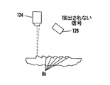
図5は、コード化センサ特徴80を読み取るためのセンサ・システム120の実施形態を示す。この本実施形態では、センサ・システム120は、光源124と光センサ128とを含む。光源124は、発光ダイオード(LED)又は半導体レーザと、LED又は半導体レーザから焦点の方向に放出されるビーム130を平行にするコリメートレンズとを含み、ビームは焦点においてインクスティックのコード化センサ特徴80上に当たる。光センサ128は、検知した光を電気信号に変換するフォトダイオードを含む。光センサ128は、検知した信号を増幅するための増幅器(図示せず)と、迷光をなくすために光源124により放出される光の波長に調整された光フィルタ(図示せず)とを含むのが好ましい。説明された光センサ128はフォトダイオードを含むが、例えば光導電体のような他の種類の光センサを使用してもよい。
FIG. 5 shows an embodiment of a sensor system 120 for reading the encoded
図5を参照すると、光源124及び光センサ128は、コード要素が光源の下の作動位置にあるときに、光源124から放出された光が光センサ128により検知されるように配向されている。このことは、光センサ128が、コード要素の表面により散乱される光によって刺激されるようにする。図6に示されるように、コード要素が作動位置にないときは、光は光センサ128によって検知されないる。図5の実施形態では、光源124及び光センサ128は、光源に対応する位置にあるインクローダ内に固定して取り付けられて、インクスティック30が供給経路に沿って支持される又は移送されるとき、光ビーム88をインクスティックのコード化マーカ70上に向ける。光源124及び光センサ128は、インクスティック30の移動経路に沿ったどのような点にも配置することができ、ローダ又はプリンタ装置の他の構造体に取り付けることができる。コード化センサ特徴80は、挿入中、又はインクスティックが供給チャネルを前方に移動するときに読み取ることができる。チャネルにおけるコードの読み取りは、インクスティックの移動経路に沿った1つ又はそれ以上の位置で、1度又はそれ以上の回数だけ発生することができる。インクが固定位置にある場合のコード要素上のセンサ装置の走査又は移動は、インクが例えば挿入又は供給中といった移動中に、コードの読み取りに対する代替的手法として行うことができる。さらに別の構成では、固定及び移動のスティックのコード読み取りを組み合わせて行うことができる。
Referring to FIG. 5,
1つの実施形態では、次いで、バイナリ(2値)信号のビット・パターン又はコードワードをコントローラ110によって定めることができる。コードワードは、コントローラ110によって、プリンタの制御システムにより多数の方法で使用可能な情報に変換することができる。例えば、コントローラ110は、基準信号を、データ構造内に格納されたデータ又はメモリ内に格納されたテーブルと比較することができる。データ構造内に格納されたデータは、コードワードに対応する関連情報をもつ複数の可能性のあるコードワードを含むことができる。関連情報は、例えばインクスティックの色、プリンタ互換性、インクスティック組成情報といったインクスティックに関連する制御及び/又は属性情報を含むことができ、或いは、インクスティックと共に使用できる、例えば、好適なカラー・テーブル、温度設定等のインクスティックに関連するプリンタ校正情報を含むことができる。制御及び/又は属性情報は、画像形成動作を制御するように、好適に装備された相変化インクジェット印刷装置のコントローラ110によって使用されることができる。例えば、制御システム110は、コード化マーカにおいてエンコードされたコードワードに対応する「関連情報」に基づいて、動作を可能又は不可にする、動作を最適化する、又は動作パラメータに影響を与える又はその設定をすることができる。
In one embodiment, a bit pattern or codeword of a binary (binary) signal can then be defined by the
コード化センサ特徴に組み込まれたデータの完全性を保存するために、コードワードに対応するコード化信号パターンを生成するようにコード要素パターンが繰り返される。パターンの繰り返しは、通常のスティック取り扱い中に発生することがある損傷がコード化センサ特徴にエンコードされたデータを破壊する可能性を減らす。同様に、製造又は梱包中に発生することがある、時折発生する欠陥は、繰り返しコード・パターンの情報を比較することにより、インクを正確に識別して反応する画像形成システムの能力を損なわないで済む。インクスティックの外面におけるパターンを繰り返すことによりデータが保存されるため、1つのパターンへの損傷が、コード化センサ特徴にエンコードされたデータの損失につながることはない。例えば、コード要素のパターンの1つが破損した場合には、冗長コード要素パターンがコードワードの正確な読み取りの可能性を増し、不完全に形成された若しくは損傷されたコード要素、又はインクスティックのばらばらな供給速度によるコードの不正確な読み取りの機会を減らす。繰り返しパターン又はパターンの繰り返しは、インクスティックの表面におけるコード要素の数、配列又は形状の繰り返しで成り、nがパターンの繰り返し回数に対応する場合に、コード化された信号パターンをn回だけ生成する。 In order to preserve the integrity of the data incorporated in the coded sensor feature, the code element pattern is repeated to generate a coded signal pattern corresponding to the codeword. Repeating the pattern reduces the likelihood that damage that may occur during normal stick handling will destroy the data encoded in the encoded sensor feature. Similarly, occasional defects that may occur during manufacturing or packaging do not detract from the ability of the imaging system to accurately identify and react to ink by repeatedly comparing code pattern information. That's it. Since data is stored by repeating the pattern on the outer surface of the ink stick, damage to one pattern does not lead to loss of data encoded in the coded sensor feature. For example, if one of the code element patterns breaks, the redundant code element pattern increases the likelihood of correct reading of the codeword, resulting in incompletely formed or damaged code elements or ink stick variations. Reduce the chances of inaccurate code reading due to high feed rates The repeating pattern or pattern repetition consists of repetition of the number, arrangement or shape of the code elements on the surface of the ink stick, and if n corresponds to the number of pattern repetitions, a coded signal pattern is generated n times. .
コード要素のパターンは、任意の好適な回数だけ繰り返すことができる。コード化センサ特徴に組み込むことができる繰り返しの数は、インクローダ内のインクスティック及びセンサの配置の選択による幾何形状によってのみ制限される。画像形成装置制御システムは、上記パターンの読み取りに重みをおくように構成して、これによって、最も発生するパターンの読み取りに、より重い重み付けが与えられ、従って、コードワードを示す可能性を高くするのが好ましい。例えば、3回発生するパターンの読み取りは、2回又はそれよりも少ない回数だけ発生するパターン読み取りよりも大きい重み付けを与えられることができる。 The pattern of code elements can be repeated any suitable number of times. The number of iterations that can be incorporated into a coded sensor feature is limited only by the geometry due to the choice of ink stick and sensor placement within the ink loader. The image forming apparatus control system is configured to place a weight on the reading of the pattern, thereby giving a higher weight to the reading of the most frequently occurring pattern and thus increasing the likelihood of indicating a code word. Is preferred. For example, a pattern reading that occurs three times may be given a higher weight than a pattern reading that occurs twice or less.
パターンの冗長性は、多数の方法でコード化センサ特徴に組み込むことができる。例えば、コード要素のパターンは、インクスティックの1つの側部より多くに形成することができる。同様に、インクスティックの同じ表面上に、線形に、並べて、交互配置して又はこれらのいずれかの組み合わせ等でパターンを繰り返すことができる。図5は、コード要素パターン84が線形に繰り返されたコード化センサ特徴の実施形態を示す。図示されるように、コード要素の各々の群は、1つ又はそれ以上のセンサを作動させて、コードワードを示す同じ信号コード化パターンを生成するように構成される。コード要素のパターンは、インクスティックの大きさや構成、並びに検知コンポーネントの配置の機会に基づいて、1つの製品に対して多数の方法で、そして、異なる製品に対しては異なる方法で繰り返すことが望ましい。
Pattern redundancy can be incorporated into coded sensor features in a number of ways. For example, the pattern of code elements can be formed on more than one side of the ink stick. Similarly, the pattern can be repeated on the same surface of the ink stick, linearly, side by side, interleaved, or any combination thereof. FIG. 5 illustrates an embodiment of a coded sensor feature in which the
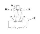
ここで図7を参照すると、デュアル(2重)トラック冗長性を有するコード化センサ特徴80の実施形態の正面図を示している。本実施形態では、2つ又はそれ以上のコード・パターン84が、インクスティック30の表面に並んで配置されている。正確なパターン読み取りの信頼性をさらに保証するために、各々のトラックのコード・パターン84は、図5に示されるように線形で繰り返される。1つの実施形態では、デュアルトラックセンサ特徴80は、インクスティック30が供給チャネルに沿って付勢されるときに、光をデュアルトラック84上に向けるための1つの光源134と、コード要素から反射された光を検知するように供給チャネルに配置された一対の光センサ138とを含むセンサ・システムにより読み取ることができる。1つの光源134と2つの光センサ138とが示されているが、任意の好適なセンサの配置又はセンサの構成を使用することができる。
Referring now to FIG. 7, a front view of an embodiment of a coded
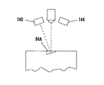
図8及び図9を参照すると、単一トラックの交互パターンの冗長性を有するコード化センサ特徴80の実施形態が示されている。この実施形態では、冗長コード・パターン84は、単一トラックに交互配置される。例えば図8に示されるように、第1のコード要素パターン84Aは、第1のセンサ140に光を反射するよう構成された傾斜表面を有することができる。図9に示されるように、第2のコード要素パターン84Bは、第2のセンサ144に光を反射するよう構成された傾斜表面を有することができる。
Referring to FIGS. 8 and 9, an embodiment of a coded
コード読み取りの信頼性及び正確性を強化するために、コード化センサ特徴に実施することができる別の特徴は、コード要素のパターンの開始及び/又は終了を示すように、コード化センサ特徴に開始/終了インジケータを組み込むことを含む。例えば、1つの実施形態では、冗長コード要素は、パターンの開始及び/又は終了を制御システムに示すように指定されたものとすることができるセンサを作動させるように構成された、コード要素のパターンの始まり及び/又は終わりに配置することができる。これらの開始/終了又は遷移インジケータ要素は、コード要素のパターンにおいては独特であるが、各々の繰り返しセグメントには共通であってもよいし、又は、各々の繰り返しセグメントにおいて、インクスティックの長さに沿ったセグメントに対して増分する位置を示すなど、独特であってもよい。別の実施形態では、コード要素のパターンの第1の及び/又は最後のコード要素は、パターンの中間コード要素とは異なる振幅でセンサを作動させ、従ってパターンの開始/終了を示すように構成することができる。例として、図10は、パターンの最初のコード要素86C及び最後のコード要素86Dが平らな表面を有するが、中間コード要素86は湾曲表面を有するコード化センサ特徴80の実施形態を示す。平らな表面を有するコード要素86C、86Dは、湾曲表面を有するコード要素86とは異なる強度で光を反射することができる。従って、コード要素の湾曲面及び平らな表面は、異なる振幅を有する信号を生成して、コントローラが、特定のコード要素によって生成される信号の振幅に基づいて、コード要素のシーケンスの始まり及び/又は終わりを判断できるようにすることができる。
To enhance the reliability and accuracy of code reading, another feature that can be implemented on the coded sensor feature is to start on the coded sensor feature to indicate the beginning and / or end of the pattern of code elements. / Incorporating an end indicator. For example, in one embodiment, the redundant code element is a pattern of code elements configured to activate a sensor that can be designated to indicate to the control system the beginning and / or end of the pattern. Can be placed at the beginning and / or end of These start / end or transition indicator elements are unique in the pattern of code elements, but may be common to each repeating segment, or the length of the ink stick in each repeating segment. It may be unique, such as showing incremental positions relative to the segments along. In another embodiment, the first and / or last code element of the pattern of code elements is configured to operate the sensor with a different amplitude than the intermediate code element of the pattern, thus indicating the start / end of the pattern be able to. By way of example, FIG. 10 shows an embodiment of a coded
当業者であれば、幾多の修正を上述の特定の実施例に行うことができることを理解するであろう。従って、特許請求の範囲は、図示され上述された特定の実施形態に限定されるものではない。本来提示される及び補正され得る特許請求の範囲は、出願人、特許権所有者などから生じることができる、現在予期されない又は理解されないものを含む、本明細書に開示される実施形態及び教示の変更、代替的手法、修正、改善、等価物、及び実質的な等価物を包含する。 Those skilled in the art will appreciate that many modifications can be made to the specific embodiments described above. Accordingly, the claims are not limited to the specific embodiments illustrated and described above. The claims originally presented and amended can be derived from the embodiments and teachings disclosed herein, including those not currently anticipated or understood, which may arise from applicants, patent owners, etc. Includes changes, alternative approaches, modifications, improvements, equivalents, and substantial equivalents.
10:インクプリンタ
12:上面
14:側面
22:インク支持リンク機構
30:インクスティック
80:コード化センサ特徴
84:コード要素パターン
86:コード要素
120:センサ・システム
124:光源
128:光センサ
10: ink printer 12: upper surface 14: side 22: ink support linkage 30: ink stick 80: coded sensor feature 84: code element pattern 86: code element 120: sensor system 124: light source 128: light sensor
Claims (10)
前記画像形成装置のインクローダ内に適合するよう形成された、インクスティック本体と、
前記インクスティック本体の外面に形成された複数のコード要素パターンとを含み、各々の前記コード要素パターンは、前記画像形成装置における少なくとも1つのセンサを作動させて同一のコード化信号パターンを生成するように形成された複数のコード要素を有し、各々の前記コード要素パターンは、また、コード要素パターンの始まりを示すための開始インジケータを形成する第1のコード要素と、コード要素パターンの終わりを示すための終了インジケータを形成する第2のコード要素とを含んでいる、
ことを特徴とするインクスティック。 An ink stick used in an ink loader of an image forming apparatus,
An ink stick body formed to fit within an ink loader of the image forming apparatus;
A plurality of code element patterns formed on an outer surface of the ink stick body, and each of the code element patterns activates at least one sensor in the image forming apparatus to generate the same encoded signal pattern. A plurality of code elements formed in each of the code element patterns, each code element pattern also indicating a first code element forming a start indicator for indicating the beginning of the code element pattern and an end of the code element pattern A second code element forming an end indicator for
An ink stick characterized by that.
前記画像形成装置のインクローダ内に適合するよう形成された、インクスティック本体と、
前記インクスティック本体の外面に形成された複数のコード要素パターンとを含み、各々の前記コード要素パターンは、インクローダのセンサを動作させて同一のコード化信号パターンを生成するように形成された複数のコード要素を有し、各々の前記コード要素パターンは、また、コード要素パターンの始まりを示す第1のコード要素と、コード要素パターンの終わりを示す第2のコード要素とを含んでいる、
ことを特徴とするインクスティック。 An ink stick used in an ink loader of an image forming apparatus,
An ink stick body formed to fit within an ink loader of the image forming apparatus;
A plurality of code element patterns formed on an outer surface of the ink stick body, and each of the code element patterns is formed to operate the ink loader sensor to generate the same encoded signal pattern. Each code element pattern also includes a first code element indicating the beginning of the code element pattern and a second code element indicating the end of the code element pattern.
An ink stick characterized by that.
Applications Claiming Priority (2)
| Application Number | Priority Date | Filing Date | Title |
|---|---|---|---|
| US11/485,606 US7648232B2 (en) | 2006-07-12 | 2006-07-12 | Solid ink stick with reliably encoded data |
| US11/485,606 | 2006-07-12 |
Publications (3)
| Publication Number | Publication Date |
|---|---|
| JP2008018720A JP2008018720A (en) | 2008-01-31 |
| JP2008018720A5 JP2008018720A5 (en) | 2011-12-22 |
| JP4987595B2 true JP4987595B2 (en) | 2012-07-25 |
Family
ID=38458025
Family Applications (1)
| Application Number | Title | Priority Date | Filing Date |
|---|---|---|---|
| JP2007177296A Expired - Fee Related JP4987595B2 (en) | 2006-07-12 | 2007-07-05 | Solid ink stick with reliable encoding data |
Country Status (6)
| Country | Link |
|---|---|
| US (2) | US7648232B2 (en) |
| EP (1) | EP1878578B1 (en) |
| JP (1) | JP4987595B2 (en) |
| KR (1) | KR101221275B1 (en) |
| CN (1) | CN101104337B (en) |
| DE (1) | DE602007002593D1 (en) |
Families Citing this family (15)
| Publication number | Priority date | Publication date | Assignee | Title |
|---|---|---|---|---|
| US7631963B2 (en) * | 2006-08-01 | 2009-12-15 | Xerox Corporation | Method of forming solid ink stick with coded mark |
| US7819513B2 (en) * | 2007-03-09 | 2010-10-26 | Xerox Corporation | Solid ink stick with multiple axis interlocking |
| US7780284B2 (en) * | 2007-03-09 | 2010-08-24 | Xerox Corporation | Digital solid ink stick identification and recognition |
| US7878641B2 (en) * | 2007-03-09 | 2011-02-01 | Xerox Corporation | Solid ink stick with reversible keying and interlocking features |
| US8025385B2 (en) * | 2008-07-16 | 2011-09-27 | Xerox Corporation | Ink sticks with visually discernible feature patterns |
| US7971980B2 (en) * | 2008-07-22 | 2011-07-05 | Xerox Corporation | Solid ink stick with reflection features |
| US8079690B2 (en) * | 2008-09-04 | 2011-12-20 | Xerox Corporation | Method for reconfiguring ink loaders to accept different ink stick identifiers |
| US8096647B2 (en) * | 2008-09-22 | 2012-01-17 | Xerox Corporation | Solid ink sticks having a verification interlock for verifying position of a solid ink stick before identifying the ink stick |
| US8052265B2 (en) * | 2008-09-22 | 2011-11-08 | Xerox Corporation | System and method for verifying position of an object before identifying the object |
| US8382269B2 (en) * | 2010-04-13 | 2013-02-26 | Xerox Corporation | System and method that enables a solid ink printer to learn a solid ink stick type |
| US8814336B2 (en) | 2011-12-22 | 2014-08-26 | Xerox Corporation | Solid ink stick configuration |
| US8876265B2 (en) | 2012-06-28 | 2014-11-04 | Xerox Corporation | Ink stick transport system |
| US8727478B2 (en) * | 2012-10-17 | 2014-05-20 | Xerox Corporation | Ink loader having optical sensors to identify solid ink sticks |
| US8777386B2 (en) | 2012-10-17 | 2014-07-15 | Xerox Corporation | Solid ink stick having identical identifying features on a plurality of edges |
| US9039158B2 (en) * | 2013-06-13 | 2015-05-26 | Xerox Corporation | Ink stick identification system |
Family Cites Families (27)
| Publication number | Priority date | Publication date | Assignee | Title |
|---|---|---|---|---|
| US5038157A (en) * | 1989-08-18 | 1991-08-06 | Apple Computer, Inc. | Apparatus and method for loading solid ink pellets into a printer |
| CA2057995C (en) * | 1990-12-30 | 1995-07-25 | Takeshi Mori | Water quality tester |
| US5223860A (en) | 1991-06-17 | 1993-06-29 | Tektronix, Inc. | Apparatus for supplying phase change ink to an ink jet printer |
| JPH05155012A (en) * | 1991-12-03 | 1993-06-22 | Ricoh Co Ltd | Recording using hot melt ink jet |
| JPH0939265A (en) | 1995-07-29 | 1997-02-10 | Seiko Epson Corp | Ink cartridge for printer and identifying device therefor |
| US5861903A (en) | 1996-03-07 | 1999-01-19 | Tektronix, Inc. | Ink feed system |
| US5734402A (en) | 1996-03-07 | 1998-03-31 | Tekronix, Inc. | Solid ink stick feed system |
| JP3455798B2 (en) | 1999-02-04 | 2003-10-14 | カシオ計算機株式会社 | Ink jet recording apparatus, ink cartridge and ink replenishing tool used therefor |
| JP4608745B2 (en) | 2000-07-21 | 2011-01-12 | コニカミノルタホールディングス株式会社 | Ink jet printer and ink cartridge for ink jet printer |
| US6924835B1 (en) | 2000-10-20 | 2005-08-02 | Silverbrook Research Pty Ltd | Method and apparatus for fault tolerant data storage on photographs |
| US6761443B2 (en) | 2002-04-29 | 2004-07-13 | Xerox Corporation | Keying feature for solid ink stick |
| US6857732B2 (en) * | 2002-04-29 | 2005-02-22 | Xerox Corporation | Visible identification of solid ink stick |
| US6840613B2 (en) | 2002-04-29 | 2005-01-11 | Xerox Corporation | Guide for solid ink stick feed |
| US20030202066A1 (en) | 2002-04-29 | 2003-10-30 | Xerox Corporation | Solid ink stick with efficient aspect ratio |
| US6755517B2 (en) | 2002-04-29 | 2004-06-29 | Xerox Corporation | Alignment feature for solid ink stick |
| US20050231584A1 (en) * | 2004-04-16 | 2005-10-20 | Rajaiah Seela R D | Ink and media sensing with a color sensor |
| US7458669B2 (en) | 2005-06-09 | 2008-12-02 | Xerox Corporation | Ink consumption determination |
| US20070080804A1 (en) * | 2005-10-07 | 2007-04-12 | Edwin Hirahara | Systems and methods for enhanced RFID tag performance |
| US7504951B2 (en) * | 2005-12-22 | 2009-03-17 | Xerox Corporation | Interface antenna |
| US7618138B2 (en) * | 2005-12-23 | 2009-11-17 | Xerox Corporation | Ink stick with electronically-readable memory device |
| US7997711B2 (en) * | 2005-12-23 | 2011-08-16 | Xerox Corporation | Supply units having an associated electronically-readable memory device |
| US7874661B2 (en) * | 2006-06-22 | 2011-01-25 | Xerox Corporation | Solid ink stick with coded markings and method and apparatus for reading markings |
| US7537326B2 (en) * | 2006-06-23 | 2009-05-26 | Xerox Corporation | Solid ink stick with coded sensor feature |
| US7631963B2 (en) * | 2006-08-01 | 2009-12-15 | Xerox Corporation | Method of forming solid ink stick with coded mark |
| US7753510B2 (en) * | 2006-10-11 | 2010-07-13 | Xerox Corporation | Solid ink composition with post-melt mixing |
| US7682010B2 (en) * | 2006-10-11 | 2010-03-23 | Xerox Corporation | Solid ink stick with coating |
| US7971980B2 (en) * | 2008-07-22 | 2011-07-05 | Xerox Corporation | Solid ink stick with reflection features |
-
2006
- 2006-07-12 US US11/485,606 patent/US7648232B2/en not_active Expired - Fee Related
-
2007
- 2007-07-05 JP JP2007177296A patent/JP4987595B2/en not_active Expired - Fee Related
- 2007-07-06 EP EP07111895A patent/EP1878578B1/en not_active Expired - Fee Related
- 2007-07-06 DE DE602007002593T patent/DE602007002593D1/en active Active
- 2007-07-11 KR KR1020070069625A patent/KR101221275B1/en not_active IP Right Cessation
- 2007-07-12 CN CN2007101287808A patent/CN101104337B/en not_active Expired - Fee Related
-
2009
- 2009-10-27 US US12/606,942 patent/US8167418B2/en active Active
Also Published As
| Publication number | Publication date |
|---|---|
| EP1878578B1 (en) | 2009-09-30 |
| US20080012916A1 (en) | 2008-01-17 |
| US8167418B2 (en) | 2012-05-01 |
| CN101104337A (en) | 2008-01-16 |
| KR101221275B1 (en) | 2013-01-11 |
| CN101104337B (en) | 2012-07-11 |
| JP2008018720A (en) | 2008-01-31 |
| US20100045756A1 (en) | 2010-02-25 |
| US7648232B2 (en) | 2010-01-19 |
| KR20080006488A (en) | 2008-01-16 |
| DE602007002593D1 (en) | 2009-11-12 |
| EP1878578A1 (en) | 2008-01-16 |
Similar Documents
| Publication | Publication Date | Title |
|---|---|---|
| JP4987595B2 (en) | Solid ink stick with reliable encoding data | |
| US7537326B2 (en) | Solid ink stick with coded sensor feature | |
| US8007095B2 (en) | Apparatus for reading markings on a solid ink stick | |
| US7517072B2 (en) | Solid ink stick with enhanced differentiation | |
| US6299274B1 (en) | Thermal ink jet printer cartridge identification | |
| JP4942161B2 (en) | Liquid storage container and inkjet recording apparatus | |
| US7553008B2 (en) | Ink loader for interfacing with solid ink sticks | |
| CN101092086A (en) | Solid ink stick with interface element | |
| MX2008003017A (en) | Digital solid ink stick identification and recognition. | |
| US7971980B2 (en) | Solid ink stick with reflection features | |
| JP5791307B2 (en) | Printer and ink tank | |
| US7513591B2 (en) | Ink tank position detection method | |
| US7891792B2 (en) | Solid ink stick with transition indicating region | |
| US8052265B2 (en) | System and method for verifying position of an object before identifying the object | |
| CN102950915A (en) | Printer apparatus and printer head | |
| JP4120564B2 (en) | Center position determining apparatus, center position determining method and printing apparatus for optical recording medium | |
| JP2004209970A (en) | Liquid tank and recording device | |
| US8079690B2 (en) | Method for reconfiguring ink loaders to accept different ink stick identifiers | |
| JP4543371B2 (en) | Printer control apparatus, printer, and printer control method | |
| KR20110114463A (en) | System and method that enables a solid ink printer to learn a solid ink stick type | |
| JP5031810B2 (en) | Inkjet recording device |
Legal Events
| Date | Code | Title | Description |
|---|---|---|---|
| A621 | Written request for application examination |
Free format text: JAPANESE INTERMEDIATE CODE: A621 Effective date: 20100705 |
|
| A521 | Request for written amendment filed |
Free format text: JAPANESE INTERMEDIATE CODE: A523 Effective date: 20100715 |
|
| A521 | Request for written amendment filed |
Free format text: JAPANESE INTERMEDIATE CODE: A523 Effective date: 20111109 |
|
| A871 | Explanation of circumstances concerning accelerated examination |
Free format text: JAPANESE INTERMEDIATE CODE: A871 Effective date: 20111109 |
|
| A131 | Notification of reasons for refusal |
Free format text: JAPANESE INTERMEDIATE CODE: A131 Effective date: 20111212 |
|
| A521 | Request for written amendment filed |
Free format text: JAPANESE INTERMEDIATE CODE: A523 Effective date: 20120308 |
|
| TRDD | Decision of grant or rejection written | ||
| A01 | Written decision to grant a patent or to grant a registration (utility model) |
Free format text: JAPANESE INTERMEDIATE CODE: A01 Effective date: 20120326 |
|
| A01 | Written decision to grant a patent or to grant a registration (utility model) |
Free format text: JAPANESE INTERMEDIATE CODE: A01 |
|
| A61 | First payment of annual fees (during grant procedure) |
Free format text: JAPANESE INTERMEDIATE CODE: A61 Effective date: 20120425 |
|
| R150 | Certificate of patent or registration of utility model |
Free format text: JAPANESE INTERMEDIATE CODE: R150 |
|
| FPAY | Renewal fee payment (event date is renewal date of database) |
Free format text: PAYMENT UNTIL: 20150511 Year of fee payment: 3 |
|
| R250 | Receipt of annual fees |
Free format text: JAPANESE INTERMEDIATE CODE: R250 |
|
| R250 | Receipt of annual fees |
Free format text: JAPANESE INTERMEDIATE CODE: R250 |
|
| LAPS | Cancellation because of no payment of annual fees |