JP4987537B2 - Game machine - Google Patents
Game machine Download PDFInfo
- Publication number
- JP4987537B2 JP4987537B2 JP2007085906A JP2007085906A JP4987537B2 JP 4987537 B2 JP4987537 B2 JP 4987537B2 JP 2007085906 A JP2007085906 A JP 2007085906A JP 2007085906 A JP2007085906 A JP 2007085906A JP 4987537 B2 JP4987537 B2 JP 4987537B2
- Authority
- JP
- Japan
- Prior art keywords
- door member
- front door
- rear door
- guide portion
- display area
- Prior art date
- Legal status (The legal status is an assumption and is not a legal conclusion. Google has not performed a legal analysis and makes no representation as to the accuracy of the status listed.)
- Expired - Fee Related
Links
Images


Description
本発明は、遊技情報を表示可能な表示領域を開閉可能な開閉装置を備えた遊技機に関する。 The present invention relates to a gaming machine including an opening / closing device capable of opening and closing a display area capable of displaying game information.
遊技機としてのスロットマシンにおいて、遊技機前面に設けられ、各種遊技情報を表示可能な表示装置の前面に、左右方向へ直線移動可能な扉部材を有する開閉装置を設け、遊技状況に応じて、扉部材を駆動源により左右方向へ移動させることにより、表示装置の表示領域を遮蔽したり開放したりして、多彩な演出を行い得るようにしたものがある(例えば、特許文献1参照)。
上述のような遊技機において、表示領域の前面に、前後に重合する左右の前扉部材及び後扉部材を設けた場合には、前、後扉部材の下部及び上部を、それぞれ左右方向へ移動可能に支持するための左右方向を向く下側ガイド部及び上側ガイド部を設ける必要がある。この場合、各扉部材の円滑な移動を可能にするには、下側ガイド部と上側ガイド部とを常に平行状態に保つように、開閉装置を強度的に優れた構成としなければならない。 In the gaming machine as described above, when left and right front door members and rear door members that overlap in the front and rear are provided in front of the display area, the lower and upper portions of the front and rear door members are moved in the left and right directions, respectively. It is necessary to provide a lower guide portion and an upper guide portion that face in the left-right direction for support. In this case, in order to allow each door member to move smoothly, the opening / closing device must have an excellent strength configuration so that the lower guide portion and the upper guide portion are always kept in a parallel state.
本発明は、従来の問題に鑑みてなされたもので、開閉装置の強度の向上を図り、前扉部材及び後扉部材を円滑に左右方向へ移動させることができるようにした遊技機を提供することを目的とする。 The present invention has been made in view of the conventional problems, and provides a gaming machine capable of improving the strength of the opening and closing device and smoothly moving the front door member and the rear door member in the left-right direction. For the purpose.
本発明によると、上記課題は、次のようにして解決される。
(1)遊技機前面に設けられ、遊技情報を表示可能な表示装置と、前記表示装置の前方に配置され、前記表示装置の表示領域を開閉可能な開閉装置とを備えた遊技機において、前記開閉装置は、前記表示領域を挟んで左右方向へ移動することにより、前記表示領域を遮蔽及び開放可能な左右の前扉部材及び前記前扉部材の後方に重合するように配置される左右の後扉部材と、前記前扉部材の下部及び前記後扉部材の下部を、それぞれ左右方向へ移動可能に支持する2本のレールを平行に設けた下側ガイド部と、前記前扉部材の上部及び前記後扉部材の上部を、それぞれ左右方向へ移動可能に支持する2本のレールを平行に設けた上側ガイド部と、前記前扉部材及び前記後扉部材をそれぞれ左右方向へ移動させるための駆動源を有する前扉部材用駆動装置及び後扉部材用駆動装置とを備え、前記下側ガイド部と前記上側ガイド部との間にあって、かつ前記表示領域を遮らない範囲に設けられる上辺と下辺とが平行する連結板により、その下辺に沿って前記下側ガイド部を固定し、その上辺に沿って前記上側ガイド部を固定して、前記下側ガイド部と前記上側ガイド部とを上下に連結する。
According to the present invention, the above problem is solved as follows.
(1) In a gaming machine provided with a display device provided on a front surface of a gaming machine and capable of displaying game information, and an opening and closing device disposed in front of the display device and capable of opening and closing a display area of the display device. The opening / closing device moves leftward and rightward across the display area, so that the display area can be shielded and opened by the left and right front door members, and the left and right rear doors arranged to overlap the front door member. A door member, a lower guide portion provided in parallel with two rails for supporting the lower portion of the front door member and the lower portion of the rear door member so as to be movable in the left-right direction, an upper portion of the front door member, and An upper guide portion provided in parallel with two rails that support the upper part of the rear door member so as to be movable in the left-right direction, and a drive for moving the front door member and the rear door member in the left-right direction, respectively. Front door member having a source And a driving device and Kotobira member driving apparatus, in the between said lower guide portion upper guide portion, and the connecting plate and the top and bottom edges provided in a range that does not obstruct the display area is in parallel, The lower guide part is fixed along the lower side , the upper guide part is fixed along the upper side, and the lower guide part and the upper guide part are connected vertically.
(2)遊技機前面に設けられ、遊技情報を表示可能な表示装置と、前記表示装置の前方に配置され、前記表示装置の表示領域を開閉可能な開閉装置とを備えた遊技機において、前記開閉装置は、前記表示領域を挟んで左右方向へ移動することにより、前記表示領域を遮蔽及び開放可能な左右の前扉部材及び前記前扉部材の後方に重合するように配置される左右の後扉部材と、前記前扉部材の下部及び前記後扉部材の下部を、それぞれ左右方向へ移動可能に支持する2本のレールを平行に設けた下側ガイド部と、前記前扉部材の上部及び前記後扉部材の上部を、それぞれ左右方向へ移動可能に支持する2本のレールを平行に設けた上側ガイド部と、前記前扉部材及び前記後扉部材をそれぞれ左右方向へ移動させるための駆動源を有する前扉部材用駆動装置及び後扉部材用駆動装置とを備え、前記下側ガイド部と前記上側ガイド部との間にあって、かつ前記表示領域を遮らない範囲に設けられる連結板により、前記下側ガイド部と前記上側ガイド部とを互いに上下に連結し、前記下側ガイド部を、前記2本のレールのうち前記前扉部材の下部を支持する方の前扉部材用下部レールが、前記後扉部材の下部を支持する方の後扉部材用下部レールに対してその前側に位置するように、前記前扉部材用下部レールと前記後扉部材用下部レールとを前後に重畳配置し、また、前記上側ガイド部を、前記2本のレールのうち前記前扉部材の上部を支持する方の前扉部材用上部レールが、前記後扉部材の上部を支持する後扉部材用上部レールに対してその上側に位置するように、前記前扉部材用上部レールと前記後扉部材用上部レールとを上下に重畳配置する。
( 2 ) In a gaming machine comprising a display device provided on a front surface of a gaming machine and capable of displaying game information; and an opening / closing device disposed in front of the display device and capable of opening and closing a display area of the display device. The opening / closing device moves leftward and rightward across the display area, so that the display area can be shielded and opened by the left and right front door members, and the left and right rear doors arranged to overlap the front door member. A door member, a lower guide portion provided in parallel with two rails for supporting the lower portion of the front door member and the lower portion of the rear door member so as to be movable in the left-right direction, an upper portion of the front door member, and An upper guide portion provided in parallel with two rails that support the upper part of the rear door member so as to be movable in the left-right direction, and a drive for moving the front door member and the rear door member in the left-right direction, respectively. Front door with source A driving device for the rear door and a driving device for the rear door member, and a connecting plate provided in a range between the lower guide portion and the upper guide portion and not blocking the display area, The upper guide portion is connected to each other vertically, and the lower guide portion includes a lower rail for a front door member that supports a lower portion of the front door member among the two rails. The lower rail for the front door member and the lower rail for the rear door member are overlapped in the front-rear direction so as to be positioned on the front side with respect to the lower rail for the rear door member supporting the lower portion, and the upper side An upper rail for the front door member that supports the upper portion of the front door member of the two rails is above the upper rail for the rear door member that supports the upper portion of the rear door member. The upper part for the front door member so as to be located at A rail and the upper rail for the rear door member are arranged so as to overlap each other.
(3)上記(1)または(2)項において、前記前扉部材を、前記連結板の前面に沿って左右方向へ移動可能に支持し、また、前記後扉部材を、前記連結板の後面に沿って左右方向へ移動可能に支持する。
( 3 ) In the above (1 ) or (2) , the front door member is supported so as to be movable in the left-right direction along the front surface of the connecting plate, and the rear door member is supported on the rear surface of the connecting plate. Is supported so as to be movable in the left-right direction.
本発明によれば、次のような効果が奏せられる。
請求項1または2記載の発明によると、前、後扉部材の下部を左右方向へ移動可能に支持するための下側ガイド部と、前、後扉部材の上部を左右方向へ移動可能に支持するための上側ガイド部とを表示領域を遮らない範囲で連結板により互いに上下に連結したことにより、下側ガイド部と上側ガイド部とを互いに平行に保つことができ、また、強度的にも優れ、前扉部材及び後扉部材を左右方向へ円滑に移動させることができる。
According to the present invention, the following effects can be obtained.
According to the first or second aspect of the invention, the lower guide portion for supporting the lower portions of the front and rear door members to be movable in the left-right direction and the upper portions of the front and rear door members are supported to be movable in the left-right direction. By connecting the upper guide portion and the upper guide portion up and down with a connecting plate within a range that does not obstruct the display area, the lower guide portion and the upper guide portion can be kept parallel to each other, and also in terms of strength. It is excellent and the front door member and the rear door member can be smoothly moved in the left-right direction.
さらに、請求項2記載の発明によると、上側ガイド部における前後方向の取付けスペースを、一本のレールの前後幅相当に抑えることができるため、前、後扉部材を前傾姿勢で取り付けても、上側ガイド部が他部品に干渉するおそれを防止することができる。
Furthermore, according to the second aspect of the present invention, the mounting space in the front-rear direction of the upper guide portion can be reduced to the width equivalent to the front-rear width of one rail. The possibility that the upper guide part interferes with other parts can be prevented.
請求項3記載の発明によると、前、後扉部材が、連結板を前後に挟んだ状態で、それぞれ左右方向へ移動するため、連結板を境にして、前、後扉部材の重さが前後に均等に作用し、前、後扉部材をバランス良く支持することができる。 According to the invention of claim 3, since the front and rear door members move in the left and right directions with the connecting plate sandwiched in the front and rear, respectively, the weight of the front and rear door members is increased with the connecting plate as a boundary. It acts evenly in the front-rear direction, and can support the front and rear door members with good balance.
図1は、本発明を適用した遊技機の斜視図である。なお、以下の説明においては、図1における左斜め下方を「前方」とし、右斜め上方を「後方」とし、左斜め上方を「左方」とし、右斜め下方を「右方」とする。 FIG. 1 is a perspective view of a gaming machine to which the present invention is applied. In the following description, the lower left diagonal in FIG. 1 is “front”, the upper right upper is “rear”, the upper left upper is “left”, and the lower right lower is “right”.
遊技機(スロットマシン)1は、外周面に複数種類の図柄が描かれた左、中、右3個の回転リール2及びその他の各種遊技機器を収容した筐体3と、筐体3の前面に開閉可能に設けられた合成樹脂製の前扉4を備え、遊技媒体をなす円板状のメダル(コインも含む)を、前扉4の前面右側に設けたメダル投入部20に投入することによって所定のゲームが行われるものである。
A gaming machine (slot machine) 1 includes a housing 3 that houses three types of left, middle, and right rotating
遊技機1の遊技は、遊技者がメダルをメダル投入部20に投入するか、または、前扉3の前面に設けられたベットボタン21により予め投入したメダル枚数を電気的に記憶されたクレジット状態のメダルの賭数を設定した後、スタートレバー22を操作して、全ての回転リール2を回転させることによって開始される。
The game of the
回転リール2が回転して所定時間が経過した後、前扉4の前面に設けられた3個のストップボタン23を順次操作して、各回転リール2の回転を停止させ、停止した3個の回転リール2の図柄の組み合わせにより、入賞の有無、及び賞の大小に応じたメダルの配当枚数が確定され、入賞した場合には、予め定めた枚数のメダルが前扉4の下部に設けたメダル受皿41に払い出される。
After a predetermined time has passed after the rotating
前扉4における前面のほぼ中央には、各回転リール2の図柄を3こまずつ視認可能な透視窓42が設けられ、また同じく上部には、表示ユニット5が設けられている。
At the front center of the
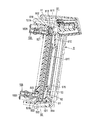
図2は、表示ユニット5の正面図、図3は、表示枠6を外した状態の表示ユニット5の正面図、図4は、斜め前方から見た表示ユニット5の分解斜視図、図5は、斜め後方から見た表示ユニット5の分解斜視図である。
2 is a front view of the
表示ユニット5は、遊技状況に応じて、光源が点灯、点滅したり、後述の表示領域71に各種遊技情報を表示させたり、表示領域71を遮蔽したり開放したりして遊技を演出するものであり、主に図4、5に示すように、前扉4の前面上部に固定される合成樹脂製の表示枠6と、遊技状況に応じた遊技情報を表示可能な表示領域71を有する表示装置7と、遊技状況に応じて表示領域71を開閉する開閉装置8と、開閉装置8に動力を伝達するための前扉部材用駆動装置10A及び後扉部材用駆動装置10Bと、表示枠6、表示装置7、開閉装置8及び各駆動装置10A、10Bが取り付けられる合成樹脂製のベース部材11と、遊技状況に応じて点灯、点滅したりして照明により遊技を演出するセンター照明装置12及び左右のサイド照明装置13、13とを備えている。
The
センター照明装置12は、図2に示すように、LED等の単一色の多数の光源121と、表示枠6の前面上部中央に固定され、内部に配置される光源121が発する光を屈折、拡散して様々な方向から光を確認できるようにした着色合成樹脂製のセンターレンズ122とを含んでいる。
As shown in FIG. 2, the
サイド照明装置13は、LED等のフルカラーの多数の光源131と、表示枠6の表面左右上部に固定され、内部に配置される光源131が発する光を屈折、拡散して様々な方向から光を確認できるようにした透明合成樹脂製のサイドレンズ132とを含んでいる。
The
表示装置7は、ベース部材11の裏面側に固定されるとともに、前面に液晶等で構成される表示領域71を有し、遊技状況に応じた遊技情報を表示領域71に表示することによって遊技の演出を盛り上げるものである。なお、表示装置7は、表示領域71に表示される遊技情報が遊技者から見やすいように若干前傾姿勢で取り付けられる。
The
ベース部材11は、表示枠6と共に前扉4の上部に固定されるとともに、表示装置7の表示領域71の大きさに相当する大きさの開口111を有し、開口111の裏面側両側部には、演出のための効果音を発生する左右のスピーカ14が取り付けられている。
The
開閉装置8は、表示装置7における表示画面71を挟むように、表示画面71の前面に沿って左右方向へ直線移動可能な左右の前扉部材81及び後扉部材82と、前扉部材81及び後扉部材82を左右方向へ移動可能に支持するためのガイド手段9とを備える。なお、開閉装置8は、表示装置7の前傾姿勢に合わせて、若干前傾姿勢で取り付けられる。
The opening /
ガイド手段9は、ベース部材11の前面に複数のボルト等(図示略)により固定される左右方向を向く上側ガイド部91及び下側ガイド部92と、上側ガイド部91と下側ガイド部92とを上下に連結する左右の連結板93、93とを有している。
The guide means 9 includes an
上側ガイド部91は、左右の前扉部材81の上部を左右方向へ移動可能に支持するための前扉部材用上部レール911と、左右の後扉部材82の上部を左右方向へ移動可能に支持するための後扉部材用上部レール912を有している。
The
前、後扉部材用上部レール911、912は、互いに平行に配置されるとともに、縦断面形状がほぼ下向き開口コ字型をなしている。前扉部材用上部レール911は、表示領域71の外側になるように、すなわち後扉部材用上部レール912の上部に固定される。換言すると、前扉部材用上部レール911及び後扉部材用上部レール912は、互いに上下方向に重畳するように配置される。これにより、上側ガイド部91における前後方向の取付けスペースを、1本のレールの前後幅に抑えることができるため、上側ガイド部91が前扉4の上部に配置されるセンター照明装置12、サイド照明装置13等に干渉することがなくなり、センター照明装置12やサイド照明装置13等の他部品の配置に与える影響を最小限に抑えることができる。
The front and rear door member
下側ガイド部92は、左右の前扉部材81の下部を左右方向へ移動可能に支持するための前扉部材用下部レール921と、左右の後扉部材82の下部を左右方向へ移動可能に支持するための後扉部材用下部レール922を有している。
The
前、後扉部材用下部レール921、922は、互いに平行に配置されるとともに、縦断面形状がほぼ上向き開口コ字型をなしている。後扉部材用下部レール922は、前扉部材用下部レール921の後部に固定される。換言すると、前扉部材用下部レール921及び後扉部材用下部レール922は、互いに前後方向に重畳するように配置される。これにより、前、後扉部材81、82の下部を安定した状態で支持することができる。
The front and rear door member
左右の連結板93は、表示装置7の表示領域71を遮ることがないように、互いに左右方向へ隔てて配置され、その上端部は、後扉部材用上部レール912の前面に連結され、また、同じく下端部は、前扉部材用下部レール921の後面と後扉部材用下部レール922の前面との間に連結される。
The left and right connecting
このように、左右の連結板93により、上側ガイド部91と下側ガイド部92とを上下に連結することにより、ガイド手段9の剛性を高めて、上側ガイド部91と下側ガイド部92とを常に平行に保ち、各扉部材81、82の円滑な作動を保証する。また、下側ガイド部92においては、連結板93を境にして、その前側に前扉部材用下部レール921が配置され、また後側に後扉部材用下部レール922が配置されるため、前、後扉部材81、82の重さが前後に均等に作用し、前、後扉部材81、82をバランス良く支持することができる。なお、本実施形態における左右の連結板93は、後扉部材用下部レール922の一部を上方へ折曲することによって形成される。
In this way, the
左右の前扉部材81は、全体が合成樹脂で形成されるとともに、上部に設けられた上部スライド部813が前扉部材用上部レール911に左右方向に移動可能に係合し、また、下部に設けられた下部スライド部814が前扉部材用下部レール921に左右方向へ移動可能に係合することにより、表示領域71及び連結板93の前面に沿って左右方向へ移動可能に支持され、表示領域71を遮蔽する遮蔽位置(図2及び図12(a)(b)参照)と開放する開放位置(図1、3及び図12(c)(d))とを間を往復移動する。
The left and right
図11に示すように、前扉部材81の上部スライド部813は、前扉部材81の上部後面から後方へ突出形成され、前扉部材用上部レール911の下部と後扉部材用上部レール912の上部との間の隙間から進入して、前扉部材用上部レール911内に摺動可能に係合する。なお、上部スライド部813には、前扉部材用上部レール911内を転動する垂直軸廻りに回転するローラ817及び水平軸廻りに回転するローラ818が設けられている。また、下部スライド部814にも、前扉部材用下部レール921内を転動する垂直軸廻りに回転するローラ(図示略)及び水平軸廻りに回転するローラ(図示略)が設けられている。
As shown in FIG. 11, the
上部スライド部813の後面には、ラック816が左右方向に沿って設けられている。このラック816は、図11に示すように、前扉部材用上部レール911の下部と後扉部材用レール912の上部間の隙間に露呈し、前扉部材用駆動装置10Aにおける後述のピニオン101に噛合する。
A
前扉部材81には、合成樹脂製の透明領域部811及び不透明領域部812が設けられている。透明領域部811は、図2、3に示すように、正面視ほぼ半月形状をなし、内側端部(左右の前扉部材81の合わせ部分)を除く周縁部が不透明領域部812の裏面に固定されている。不透明領域部812には、前扉部材81の剛性を高めるため、透明領域部811の円弧部分の外周に沿って前方へ突出する突条部815が一体的に形成されている。
The
透明領域部811は、円周部分が不透明領域部812の突条部815の裏側に固定されることにより、板厚が薄いアクリル樹脂板により形成してもその剛性は保たれる。また、左右の前扉部材81が遮蔽位置にあるとき、左右の透明領域部811、811の内側端部同士が当接し合うことによって、左右の透明領域部811、811により正面視円形の透明領域を形成する。これにより、左右の前扉部材81が遮蔽位置にあっても、円形の透明領域越しに、表示領域71に表示される映像や文字情報等を透視することができる。この場合、透明領域部811の内側端部には不透明領域が存在しないため、表示領域71に表示される映像や文字情報等を不透明領域部分に遮られることなく明視することができる。さらには、図2、3に示すように、左右の透明領域部811、811に線画811a、811aを描写することによって、左右の前扉部材81、81が遮蔽位置にあるとき、遊技領域71に表示される映像や文字情報等に線画を組み合わせた演出を表示させることができる。
The
合成樹脂製の後扉部材82は、上部に設けられた上部スライド部821が後扉部材用上部レール912内に左右方向へ移動可能に係合し、また、下部に設けられた下部スライド部822が後扉部材用下部レール922内に左右方向へ移動可能に係合することにより、連結板93の後面及び表示領域71の前面に沿って左右方向へ移動可能に支持され、表示領域71を遮蔽する遮蔽位置(図1及び図12(a)(c))と、開放する開放位置(図3及び図12(a)(d))とに移動可能である。なお、上部スライド部821には、後扉部材用上部レール912内を転動する垂直軸廻りに回転するローラ826及び水平軸廻りに回転するローラ827が設けられている。また、下部スライド部822にも、後扉部材用下部レール922内を転動する垂直軸廻りに回転するローラ(図示略)及び水平軸廻りに回転するローラ(図示略)が設けられている。
The
後扉部材82における下部スライド部822の後面には、ラック825が左右方向に沿って設けられている。このラック825は、図11に示すように、後扉部材用駆動装置10Bにおける後述のピニオン101Bに噛合する。
On the rear surface of the
後扉部材82における上部スライド部821と下部スライド部822の間に形成される正面視矩形状の遮蔽部823は、表示領域71を遮蔽する位置にあっても、表示領域71に表示される映像の輪郭や色彩等を僅かに視認できる程度の半透明に形成される。また、遮蔽部823の内側端部(左右の遮蔽部823の合わせ部分)には、後方へ所定量突出する折返し部824が設けられている。
Even when the shielding
折返し部824は、前後厚さが薄く形成される遮蔽部823の剛性を高めて、後扉部材82全体の剛性を高める作用を有している。これにより、後扉部材82が遮蔽位置にあるとき、互いの内側端部が変形することなく確実に当接し合うことができ、後扉部材82の合わせ部分の隙間から表示領域71が発する光が漏れることを防止する。また、折返し部824の後端は、表示領域71に近接して、表示領域71と後扉部材82との間の隙間を僅かなものとしている。これにより、例えば、左右の前扉部材81が開放位置にあって、左右の後扉部材82のうち一方の後扉部材82のみが開放位置にあるときなど、表示領域71を遮蔽している他方の後扉部材82の内側端部と表示領域71との間から表示領域71に表示されている映像が見えたりすることを防止して、見栄え良く表示領域71を遮蔽することができる。
The folded
左右の前扉部材用駆動装置10A及び左右の後扉部材用駆動装置10Bは、ブラケット102A、102Bを介してベース部材11の裏面に取り付けられるモータ103A、103Bと、モータ103A、103Bにより回転させられる垂直軸廻りに回転可能なピニオン101A、101Bとをそれぞれ備えている。
The left and right front door
左右の前扉部材用駆動装置10A、10Aは、左右の前扉部材81、81をそれぞれ左右方向へ直線移動させるもので、ベース部材11の裏面上部の左右に取り付けられる。ピニオン101A、101Aは、ベース部材11の左右上部に設けられた横長の開口部112、112からベース部材11の表面に露出して、左右の前扉部材81、81のラック816、816にそれぞれ噛合し、モータ103A、103Aの動力を左右の前扉部材81、81に伝達する。
The left and right front door member drive devices 10 </ b> A and 10 </ b> A move the left and right
左右の後扉部材用駆動装置10B、10Bは、左右の後扉部材82、82を左右方向へ直線移動させるもので、ベース部材11の裏面下部の左右に取り付けられる。ピニオン101B、101Bは、ベース部材11の左右下部に設けられた横長の開口部113、113からベース部材11の表面に露出して、左右の後扉部材82、82のラック825、825にそれぞれ噛合し、モータ103B、103Bの動力を左右の後扉部材82、82に伝達する。
The left and right rear door member driving devices 10 </ b> B and 10 </ b> B linearly move the left and right
次に、前扉部材81及び後扉部材82の動作態様について説明する。
動作態様は、遊技状況に応じて、左右の各扉部材81、82が遮蔽位置にあって、前後に重畳した状態、すなわち表示装置7の表示領域71を二重で遮蔽する図12(a)に示す第1遮蔽態様と、後扉部材82が開放位置にあり、前扉部材81が遮蔽位置にある図12(b)に示す第2遮蔽態様と、前扉部材81が開放位置にあり、後扉部材82が遮蔽位置にある図12(c)に示す第3遮蔽態様と、全ての開閉体81、82が開放位置にあって、表示領域71を完全に開放する図12(d)に示す開放態様と、表示領域71の右半分または左半分のみを遮蔽する図示略の半遮蔽状態とに変化可能である。
Next, operation modes of the
The operation mode is such that the left and
図12(a)に示す第1遮蔽態様は、前扉部材81と後扉部材82が前後に重合して、表示領域71を二重遮蔽しているため、表示領域71に表示される映像や文字情報を殆んど視認することはできない。図12(b)に示す第2遮蔽態様は、左右の前扉部材81のみが表示領域71を遮蔽しているため、前扉部材81における透明領域部811の範囲に限定して、透明領域部811に描写された線画811aを混在させた形態で、表示領域71に表示される映像や文字情報を視認することができる。図12(c)に示す第3遮蔽態様は、後扉部材82のみが表示領域71を遮蔽しているため、表示領域71に表示される映像や文字情報の色彩や輪郭等を僅かに視認することができる。図12(d)に示す開放状態は、表示領域71の前面に遮蔽物が存在しないため、表示領域71に表示される映像や文字情報を全て明視することができる。
In the first shielding mode shown in FIG. 12 (a), the
以上、本発明の実施形態について説明したが、本発明の要旨を逸脱しない範囲内で、本実施形態に対して、次のような種々の変形や変更を施すことが可能である。(i)遊技機1を、遊技媒体がメダル(コインを含む)とするスロットマシンに代えて、遊技媒体がパチンコ玉であるパチンコ機、スロットマシン、及びその他の遊技機とする。
(ii)下側ガイド部92を、前扉部材用下部レール921が後扉部材用下部レール922に対してその外側、すなわち下側になるように、前扉部材用下部レール921と後扉部材用下部レール922とを上下に重畳配置する。または、下側ガイド部92のレールのみを上下に重畳配置する。
Although the embodiment of the present invention has been described above, the following various modifications and changes can be made to the present embodiment without departing from the gist of the present invention. (I) The
(Ii) The front guide member
1 遊技機(スロットマシン)
2 回転リール
3 筐体
4 前扉
5 表示ユニット
6 表示枠
7 表示装置
8 開閉装置
9 ガイド手段
10A 前扉部材用駆動装置
10B 後扉部材用駆動装置
11 ベース部材
12 センター照明装置
13 サイド照明装置
14 スピーカ
20 メダル投入部
21 ベットボタン
22 スタートレバー
23 ストップボタン
41 メダル受皿
42 透視窓
71 表示領域
81 前扉部材
82 後扉部材
91 上側ガイド部
92 下側ガイド部
93 連結板
101A、B ピニオン
102A、B ブラケット
103A、B モータ
111 開口
112、113 開口部
121 光源
122 センターレンズ
131 光源
132 サイドレンズ
811 透明領域部
811a 線画
812 不透明領域部
813 上部スライド部
814 下部スライド部
815 突条部
816 ラック
817、818 ローラ
821 上部スライド部
822 下部スライド部
823 遮蔽部
824 折返し部
825 ラック
826、827 ローラ
911 前扉部材用上部レール
912 後扉部材用上部レール
921 前扉部材用下部レール
922 後扉部材用下部レール
1 gaming machine (slot machine)
2 Rotating reel 3
Claims (3)
前記開閉装置は、前記表示領域を挟んで左右方向へ移動することにより、前記表示領域を遮蔽及び開放可能な左右の前扉部材及び前記前扉部材の後方に重合するように配置される左右の後扉部材と、
前記前扉部材の下部及び前記後扉部材の下部を、それぞれ左右方向へ移動可能に支持する2本のレールを平行に設けた下側ガイド部と、
前記前扉部材の上部及び前記後扉部材の上部を、それぞれ左右方向へ移動可能に支持する2本のレールを平行に設けた上側ガイド部と、
前記前扉部材及び前記後扉部材をそれぞれ左右方向へ移動させるための駆動源を有する前扉部材用駆動装置及び後扉部材用駆動装置とを備え、
前記下側ガイド部と前記上側ガイド部との間にあって、かつ前記表示領域を遮らない範囲に設けられる上辺と下辺とが平行する連結板により、その下辺に沿って前記下側ガイド部を固定し、その上辺に沿って前記上側ガイド部を固定して、前記下側ガイド部と前記上側ガイド部とを上下に連結したことを特徴とする遊技機。 In a gaming machine comprising a display device provided on the front surface of a gaming machine and capable of displaying game information, and an opening and closing device disposed in front of the display device and capable of opening and closing a display area of the display device.
The opening and closing device moves left and right across the display area, and thereby the left and right front door members capable of shielding and opening the display area and the left and right front door members arranged to overlap the front door member. A rear door member;
A lower guide portion provided in parallel with two rails that respectively support the lower portion of the front door member and the lower portion of the rear door member so as to be movable in the left-right direction;
An upper guide part provided in parallel with two rails for supporting the upper part of the front door member and the upper part of the rear door member so as to be movable in the left-right direction;
A front door member drive device and a rear door member drive device having a drive source for moving the front door member and the rear door member in the left-right direction,
The lower guide portion is fixed along the lower side by a connecting plate between the lower guide portion and the upper guide portion and provided in a range not to obstruct the display area, and the upper side and the lower side are parallel to each other. A gaming machine, wherein the upper guide portion is fixed along the upper side thereof, and the lower guide portion and the upper guide portion are connected vertically.
前記開閉装置は、前記表示領域を挟んで左右方向へ移動することにより、前記表示領域を遮蔽及び開放可能な左右の前扉部材及び前記前扉部材の後方に重合するように配置される左右の後扉部材と、
前記前扉部材の下部及び前記後扉部材の下部を、それぞれ左右方向へ移動可能に支持する2本のレールを平行に設けた下側ガイド部と、
前記前扉部材の上部及び前記後扉部材の上部を、それぞれ左右方向へ移動可能に支持する2本のレールを平行に設けた上側ガイド部と、
前記前扉部材及び前記後扉部材をそれぞれ左右方向へ移動させるための駆動源を有する前扉部材用駆動装置及び後扉部材用駆動装置とを備え、
前記下側ガイド部と前記上側ガイド部との間にあって、かつ前記表示領域を遮らない範囲に設けられる連結板により、前記下側ガイド部と前記上側ガイド部とを互いに上下に連結し、
前記下側ガイド部を、前記2本のレールのうち前記前扉部材の下部を支持する方の前扉部材用下部レールが、前記後扉部材の下部を支持する方の後扉部材用下部レールに対してその前側に位置するように、前記前扉部材用下部レールと前記後扉部材用下部レールとを前後に重畳配置し、また、前記上側ガイド部を、前記2本のレールのうち前記前扉部材の上部を支持する方の前扉部材用上部レールが、前記後扉部材の上部を支持する後扉部材用上部レールに対してその上側に位置するように、前記前扉部材用上部レールと前記後扉部材用上部レールとを上下に重畳配置したことを特徴とする遊技機。 In a gaming machine comprising a display device provided on the front surface of a gaming machine and capable of displaying game information, and an opening and closing device disposed in front of the display device and capable of opening and closing a display area of the display device.
The opening and closing device moves left and right across the display area, and thereby the left and right front door members capable of shielding and opening the display area and the left and right front door members arranged to overlap the front door member. A rear door member;
A lower guide portion provided in parallel with two rails that respectively support the lower portion of the front door member and the lower portion of the rear door member so as to be movable in the left-right direction;
An upper guide part provided in parallel with two rails for supporting the upper part of the front door member and the upper part of the rear door member so as to be movable in the left-right direction;
A front door member drive device and a rear door member drive device having a drive source for moving the front door member and the rear door member in the left-right direction,
By connecting the lower guide portion and the upper guide portion up and down by a connecting plate provided in a range between the lower guide portion and the upper guide portion and not blocking the display area,
Of the two rails, the lower rail for the front door member that supports the lower portion of the front door member, and the lower rail for the rear door member that supports the lower portion of the rear door member. The lower rail for the front door member and the lower rail for the rear door member are arranged so as to overlap with each other so that the lower rail for the front door member is located on the front side, and the upper guide portion is positioned on the two rails. The upper part for the front door member so that the upper rail for the front door member that supports the upper part of the front door member is positioned above the upper rail for the rear door member that supports the upper part of the rear door member. A gaming machine characterized in that a rail and the upper rail for the rear door member are arranged so as to overlap each other.
Priority Applications (1)
| Application Number | Priority Date | Filing Date | Title |
|---|---|---|---|
| JP2007085906A JP4987537B2 (en) | 2007-03-28 | 2007-03-28 | Game machine |
Applications Claiming Priority (1)
| Application Number | Priority Date | Filing Date | Title |
|---|---|---|---|
| JP2007085906A JP4987537B2 (en) | 2007-03-28 | 2007-03-28 | Game machine |
Publications (2)
| Publication Number | Publication Date |
|---|---|
| JP2008237755A JP2008237755A (en) | 2008-10-09 |
| JP4987537B2 true JP4987537B2 (en) | 2012-07-25 |
Family
ID=39909784
Family Applications (1)
| Application Number | Title | Priority Date | Filing Date |
|---|---|---|---|
| JP2007085906A Expired - Fee Related JP4987537B2 (en) | 2007-03-28 | 2007-03-28 | Game machine |
Country Status (1)
| Country | Link |
|---|---|
| JP (1) | JP4987537B2 (en) |
Families Citing this family (3)
| Publication number | Priority date | Publication date | Assignee | Title |
|---|---|---|---|---|
| JP6281095B2 (en) * | 2016-07-08 | 2018-02-21 | 株式会社サンセイアールアンドディ | Game machine |
| JP6281096B2 (en) * | 2016-07-08 | 2018-02-21 | 株式会社サンセイアールアンドディ | Game machine |
| JP6893029B2 (en) * | 2017-10-18 | 2021-06-23 | 株式会社サンセイアールアンドディ | Pachinko machine |
Family Cites Families (3)
| Publication number | Priority date | Publication date | Assignee | Title |
|---|---|---|---|---|
| JP2004153244A (en) * | 2002-08-30 | 2004-05-27 | Hitachi Metals Ltd | Ferrite core, device for catv, and bidirectional catv system |
| JP4455834B2 (en) * | 2003-05-29 | 2010-04-21 | 株式会社大都技研 | Amusement stand |
| JP4241253B2 (en) * | 2003-07-24 | 2009-03-18 | 株式会社大都技研 | Amusement stand |
-
2007
- 2007-03-28 JP JP2007085906A patent/JP4987537B2/en not_active Expired - Fee Related
Also Published As
| Publication number | Publication date |
|---|---|
| JP2008237755A (en) | 2008-10-09 |
Similar Documents
| Publication | Publication Date | Title |
|---|---|---|
| JP5270853B2 (en) | Game machine | |
| JP2010119730A (en) | Game machine | |
| JP5467248B2 (en) | Game machine and effect display device | |
| KR101417747B1 (en) | Backlight unit and liquid crystal display device and game machine with the same | |
| JP4987537B2 (en) | Game machine | |
| JP5138250B2 (en) | Game machine | |
| JP5222107B2 (en) | Game machine | |
| JP2013169260A (en) | Pachinko game machine | |
| JP2010119713A (en) | Game machine | |
| JP4932560B2 (en) | Game machine | |
| JP5616567B2 (en) | Game machine | |
| JP2009000379A (en) | Game machine | |
| JP2010119715A (en) | Game machine | |
| JP2008295965A (en) | Game machine | |
| JP5037194B2 (en) | Game machine | |
| JP6744533B2 (en) | Movable unit for gaming machine and gaming machine | |
| JP5330653B2 (en) | Game machine | |
| JP2017202364A (en) | Game machine | |
| JP6729937B2 (en) | Amusement machine | |
| JP6981642B2 (en) | Pachinko machine | |
| JP2015120009A (en) | Pachinko game machine | |
| JP6308758B2 (en) | Game machine | |
| JP6298379B2 (en) | Game machine | |
| JP6317205B2 (en) | Game machine | |
| JP2014128317A (en) | Pinball game machine |
Legal Events
| Date | Code | Title | Description |
|---|---|---|---|
| A621 | Written request for application examination |
Free format text: JAPANESE INTERMEDIATE CODE: A621 Effective date: 20091214 |
|
| A977 | Report on retrieval |
Free format text: JAPANESE INTERMEDIATE CODE: A971007 Effective date: 20120126 |
|
| A131 | Notification of reasons for refusal |
Free format text: JAPANESE INTERMEDIATE CODE: A131 Effective date: 20120131 |
|
| A521 | Written amendment |
Free format text: JAPANESE INTERMEDIATE CODE: A523 Effective date: 20120402 |
|
| TRDD | Decision of grant or rejection written | ||
| A01 | Written decision to grant a patent or to grant a registration (utility model) |
Free format text: JAPANESE INTERMEDIATE CODE: A01 Effective date: 20120424 |
|
| A01 | Written decision to grant a patent or to grant a registration (utility model) |
Free format text: JAPANESE INTERMEDIATE CODE: A01 |
|
| A61 | First payment of annual fees (during grant procedure) |
Free format text: JAPANESE INTERMEDIATE CODE: A61 Effective date: 20120425 |
|
| R150 | Certificate of patent or registration of utility model |
Ref document number: 4987537 Country of ref document: JP Free format text: JAPANESE INTERMEDIATE CODE: R150 Free format text: JAPANESE INTERMEDIATE CODE: R150 |
|
| FPAY | Renewal fee payment (event date is renewal date of database) |
Free format text: PAYMENT UNTIL: 20150511 Year of fee payment: 3 |
|
| R250 | Receipt of annual fees |
Free format text: JAPANESE INTERMEDIATE CODE: R250 |
|
| R250 | Receipt of annual fees |
Free format text: JAPANESE INTERMEDIATE CODE: R250 |
|
| R250 | Receipt of annual fees |
Free format text: JAPANESE INTERMEDIATE CODE: R250 |
|
| R250 | Receipt of annual fees |
Free format text: JAPANESE INTERMEDIATE CODE: R250 |
|
| R250 | Receipt of annual fees |
Free format text: JAPANESE INTERMEDIATE CODE: R250 |
|
| R250 | Receipt of annual fees |
Free format text: JAPANESE INTERMEDIATE CODE: R250 |
|
| LAPS | Cancellation because of no payment of annual fees |