JP4987318B2 - Ink jet head and manufacturing method thereof - Google Patents
Ink jet head and manufacturing method thereof Download PDFInfo
- Publication number
- JP4987318B2 JP4987318B2 JP2006036571A JP2006036571A JP4987318B2 JP 4987318 B2 JP4987318 B2 JP 4987318B2 JP 2006036571 A JP2006036571 A JP 2006036571A JP 2006036571 A JP2006036571 A JP 2006036571A JP 4987318 B2 JP4987318 B2 JP 4987318B2
- Authority
- JP
- Japan
- Prior art keywords
- adhesive
- bonded
- channel substrate
- epoxy resin
- channel
- Prior art date
- Legal status (The legal status is an assumption and is not a legal conclusion. Google has not performed a legal analysis and makes no representation as to the accuracy of the status listed.)
- Active
Links
Images


Classifications
-
- B—PERFORMING OPERATIONS; TRANSPORTING
- B41—PRINTING; LINING MACHINES; TYPEWRITERS; STAMPS
- B41J—TYPEWRITERS; SELECTIVE PRINTING MECHANISMS, i.e. MECHANISMS PRINTING OTHERWISE THAN FROM A FORME; CORRECTION OF TYPOGRAPHICAL ERRORS
- B41J2202/00—Embodiments of or processes related to ink-jet or thermal heads
- B41J2202/01—Embodiments of or processes related to ink-jet heads
- B41J2202/10—Finger type piezoelectric elements
Description
本発明は、インクジェットヘッド及びその製造方法に関する。 The present invention relates to Lee inkjet head and a manufacturing method thereof.
従来から、メッシュ状のスクリーンに所望のパターンを形成して当該パターンを通過したインクを記録媒体に印刷する「スクリーン印刷技術」が、液晶のカラーフィルターの製造や液晶配向膜の塗布、有機EL(ElectroLuminescence)等の各種精密電子部品の製造等に広く適用されている。 Conventionally, “screen printing technology” in which a desired pattern is formed on a mesh-like screen and ink that has passed through the pattern is printed on a recording medium has been produced by manufacturing a liquid crystal color filter, applying a liquid crystal alignment film, and organic EL ( Widely applied to the production of various precision electronic components such as ElectroLuminescence).
しかしながら、上記スクリーン印刷技術には、印刷前に予めスクリーンを設計・製造しなければならなかったり、パターンを変更するごとに新規のスクリーンを設計・製造し直さなければならなかったりして簡単・安価に画像等の印刷をおこなえないという不都合があるため、近年では、簡単・安価に画像等の記録をおこなえる「インクジェット技術」が上記スクリーン印刷技術に代わる技術として適用され始めている。 However, the above screen printing technology requires a simple and inexpensive design because the screen must be designed and manufactured in advance before printing, or a new screen must be designed and manufactured every time the pattern is changed. However, in recent years, “inkjet technology” capable of recording images and the like easily and inexpensively has begun to be applied as an alternative to the screen printing technology.
インクジェット技術というのは、インクを滴として吐出する「インクジェットヘッド」を記録媒体上で走査して当該記録媒体に画像等を記録する技術であるが、上記スクリーン印刷技術では記録媒体として樹脂製記録媒体を使用するのが主であるため、当該インクジェット技術を上記スクリーン印刷技術の代替技術として使用する場合(記録媒体として樹脂製記録媒体を適用する場合)には、インクとして、樹脂に浸透し易く記録媒体そのものの耐久性を向上させることができる「溶剤系インク」が使用されている。 The ink jet technology is a technology for recording an image or the like on a recording medium by scanning an “ink jet head” that ejects ink as droplets on the recording medium. In the screen printing technique, a resin recording medium is used as the recording medium. Therefore, when using the inkjet technology as an alternative technology to the screen printing technology (when applying a resin recording medium as the recording medium), the ink is likely to penetrate the resin as a recording medium. “Solvent ink” that can improve the durability of the medium itself is used.
ここで、上記インクジェットヘッドはそれを構成する部材同士が接着剤で接着されているが、溶剤系インクを適用した場合には当該溶剤系インクが接着剤を溶解してしまうため、当該接着剤として、溶剤に対し耐性を有する「エポキシ系接着剤」を使用するのがよい。エポキシ系接着剤の一例が特許文献1に開示されている。具体的に特許文献1に記載の技術では、接着剤を乾燥・硬化させるのに常温から100℃までの昇温速度を緩やかに設定し、これにより架橋密度を高めて溶剤系インクに対する耐性を高めている(段落番号0034〜0041参照)。
ところで、上記エポキシ系接着剤には「エポキシ樹脂」と「硬化剤」とが含有されているが、当該エポキシ系接着剤は硬化剤の種類により硬化するための反応機構が異なっている。当該硬化剤としては一般的に「アミン系硬化剤」が適用されることが多く、その他に「イミダゾール系硬化剤」が適用されることもある。 By the way, although the said epoxy-type adhesive agent contains "epoxy resin" and "curing agent", the reaction mechanism for the said epoxy-type adhesive agent to cure | harden with the kind of hardening | curing agent differs. In general, an “amine curing agent” is often used as the curing agent, and an “imidazole curing agent” is sometimes applied.
硬化剤としてアミン系硬化剤が適用されたアミン系のエポキシ系接着剤では、アミン系硬化剤中に存する1級アミンの活性が高く、当該1級アミンがエポキシ樹脂中のエポキシ基を室温で開環させてこれに付加し、2級アミンと水酸基とが生成され、この反応が繰り返しおこなわれて鎖が線状に成長する。そして上記2級アミンが更にエポキシ樹脂中のエポキシ基と反応すると、3級アミンと水酸基とが生成され、この反応が繰り返しおこなわれて3次元の架橋構造が形成される。このような経緯から、アミン系のエポキシ系接着剤は溶剤に対しある程度の耐性を有する。 In an amine-based epoxy adhesive to which an amine-based curing agent is applied as a curing agent, the activity of the primary amine present in the amine-based curing agent is high, and the primary amine opens the epoxy group in the epoxy resin at room temperature. A ring is added to this to produce a secondary amine and a hydroxyl group, and this reaction is repeated to grow a chain in a linear form. When the secondary amine further reacts with an epoxy group in the epoxy resin, a tertiary amine and a hydroxyl group are generated, and this reaction is repeated to form a three-dimensional crosslinked structure. For these reasons, amine-based epoxy adhesives have a certain degree of resistance to solvents.
しかしながら、アミン系のエポキシ系接着剤では、上記架橋構造中にアミン系硬化剤が取り込まれるとともに水酸基が含まれているため、当該アミン系のエポキシ系接着剤は溶剤を吸収して膨潤しやすいという欠点を有している。そこで架橋構造中に残留するアミノ基や水酸基を未反応のエポキシ基と反応させればよいのであるが、当該反応を開始させようとすると、その時点で既に架橋構造が形成されガラス転移点が高くなっているため、ガラス転移点以上に加熱しなければ当該反応を開始させることができない。以上から、アミン系のエポキシ系接着剤を十分に硬化させるには、150〜200℃以上の高温で加熱しなければならない。 However, in an amine-based epoxy adhesive, an amine-based curing agent is incorporated into the above-mentioned crosslinked structure and a hydroxyl group is included. Therefore, the amine-based epoxy adhesive absorbs a solvent and easily swells. Has drawbacks. Therefore, the amino group and hydroxyl group remaining in the crosslinked structure may be reacted with an unreacted epoxy group. However, when the reaction is started, the crosslinked structure is already formed at that point and the glass transition point is high. Therefore, the reaction cannot be started unless the glass transition point is heated. From the above, in order to sufficiently cure the amine-based epoxy adhesive, it must be heated at a high temperature of 150 to 200 ° C. or higher.
これに対し、硬化剤としてイミダゾール系硬化剤が適用されたイミダゾール系のエポキシ系接着剤では、上記アミン系硬化剤とは硬化反応機構が異なり、イミダゾールが硬化反応を開始させる触媒として機能し、硬化反応が開始されると、エポキシ樹脂同士がエーテル結合により架橋する。この反応機構では、架橋物中に極性基が含まれてはおらず、架橋点間距離も短くなっている。このような経緯から、当該イミダゾール系のエポキシ系接着剤は、上記アミン系のエポキシ系接着剤のように溶剤を吸収するという欠点はなく、溶剤に対しても耐性を有している。 In contrast, an imidazole-based epoxy adhesive to which an imidazole-based curing agent is applied as a curing agent has a curing reaction mechanism different from that of the amine-based curing agent, and imidazole functions as a catalyst for initiating a curing reaction. When the reaction is started, the epoxy resins are crosslinked by an ether bond. In this reaction mechanism, a polar group is not contained in the cross-linked product, and the distance between cross-linking points is also short. From such circumstances, the imidazole-based epoxy adhesive does not have the disadvantage of absorbing the solvent unlike the amine-based epoxy adhesive, and has resistance to the solvent.
しかしながら、ビスフェノールA型エポキシ樹脂やビスフェノールF型エポキシ樹脂などの一般的なエポキシ樹脂と一般的なイミダゾール系硬化剤とを組み合わせて用いると、十分な耐溶剤性を得るためには150℃程度の高温で加熱しなければならない。 However, when a general epoxy resin such as bisphenol A type epoxy resin or bisphenol F type epoxy resin is used in combination with a general imidazole curing agent, a high temperature of about 150 ° C. is required to obtain sufficient solvent resistance. Must be heated at.
インクジェットヘッドは基本的にそれを構成する部材同士が互いに異なる線膨張係数(熱膨張係数)を有しているため、高温で硬化させると、硬化後において温度が室温に戻る際に、部材間の収縮率の違いから硬化後の接着剤と部材との間で収縮の差による応力が掛かる。 Ink-jet heads basically have different linear expansion coefficients (thermal expansion coefficients) among the members that make up the ink-jet head. When cured at a high temperature, when the temperature returns to room temperature after curing, Due to the difference in shrinkage rate, stress due to the difference in shrinkage is applied between the cured adhesive and the member.
その結果、接着剤そのものにひび割れが生じたり、接着力が低下したりする。特に、インクジェットヘッドが製品として輸送される場合や、インクジェットヘッドの運転とその停止との繰り返し操作に供される場合に、それに伴って度重なる温度変動を受け、ひび割れや接着力の低下が起こりやすい。また部材に着目した場合にも、部材にひび割れが発生したり、部材が歪んだり、一方の部材が他方の部材から剥がれ落ちたりする可能性がある。 As a result, the adhesive itself is cracked or the adhesive strength is reduced. In particular, when the inkjet head is transported as a product, or when it is subjected to repeated operations of operation and stop of the inkjet head, it is subject to repeated temperature fluctuations, and cracks and adhesive strength are likely to occur. . Further, when attention is paid to the member, there is a possibility that the member is cracked, the member is distorted, or one member is peeled off from the other member.
更に、インクジェットヘッドが一構成部材として圧電素子を有している場合に、接着剤を高温で硬化させると、当該圧電素子で脱分極が生じて当該圧電素子の性能が低下する。 Furthermore, when the ink jet head has a piezoelectric element as one constituent member, if the adhesive is cured at a high temperature, depolarization occurs in the piezoelectric element, and the performance of the piezoelectric element decreases.
本発明の目的は、溶剤系インクに対して耐性を有し、部材のひび割れ、歪み、剥離等を防止することができるインクジェットヘッド及びその製造方法を提供することで
ある。
An object of the present invention has a resistance to solvent-based inks, cracking of parts member, distortion is to provide an ink jet head and a manufacturing method thereof capable of preventing the peeling.
第1の発明は、
インクのチャネルを有するチャネル基板と、前記チャネル基板に対し接着される被接着部材と、前記被接着部材に対し更に接着される第2の被接着部材と、を備えるインクジェットヘッドであって、
前記チャネル基板と前記被接着部材とが、又は前記被接着部材と前記第2の被接着部材とが、下記接着剤で接着され、
前記接着剤が、主剤と硬化剤とが混合された接着剤であって、
前記主剤が、2官能以下の官能基を有する第1のエポキシ樹脂と3官能以上の官能基を有する第2のエポキシ樹脂とを含有し、前記第1のエポキシ樹脂が当該主剤中に20〜90重量%含有されかつ前記第2のエポキシ樹脂が当該主剤中に10〜80重量%含有されており、
前記硬化剤がイミダゾール類であり、
100重量部の前記主剤に対し6重量部以上の前記硬化剤が混合され、かつ、前記第1のエポキシ樹脂がビスフェノールF型エポキシ樹脂であることを特徴としている。
The first invention is
An ink-jet head comprising: a channel substrate having an ink channel; a member to be bonded to the channel substrate; and a second member to be bonded to the member to be bonded.
The channel substrate and the adherend member, or the adherend member and the second adherend member are bonded with the following adhesive,
The adhesive is an adhesive in which a main agent and a curing agent are mixed,
The main agent contains a first epoxy resin having a bifunctional or lower functional group and a second epoxy resin having a trifunctional or higher functional group, and the first epoxy resin is 20 to 90 in the main agent. And the second epoxy resin is contained in an amount of 10 to 80% by weight in the main agent,
The curing agent is an imidazole,
6 parts by weight or more of the curing agent is mixed with 100 parts by weight of the main agent, and the first epoxy resin is a bisphenol F type epoxy resin .
第1の発明のインクジェットヘッドにおいては、
前記チャネル基板と前記被接着部材との間で、又は前記被接着部材と前記第2の被接着部材との間で、12ppm/Kを超える線膨張係数の差があってもよい。
In the inkjet head of the first aspect of the invention,
There may be a difference in linear expansion coefficient exceeding 12 ppm / K between the channel substrate and the adherend member or between the adherend member and the second adherend member.
第2の発明は、
インクのチャネルを有するチャネル基板と、前記チャネル基板に対し接着される被接着部材と、前記被接着部材に対し更に接着される第2の被接着部材と、を備えるインクジェットヘッドであって、
前記チャネル基板と前記被接着部材とが、又は前記被接着部材と前記第2の被接着部材とが、下記接着剤で接着され、
前記接着剤が、主剤と硬化剤とが混合された接着剤であって、
前記主剤が、2官能以下の官能基を有する第1のエポキシ樹脂と3官能以上の官能基を有する第2のエポキシ樹脂とを含有し、前記第1のエポキシ樹脂が当該主剤中に20〜90重量%含有されかつ前記第2のエポキシ樹脂が当該主剤中に10〜80重量%含有されており、
前記硬化剤がイミダゾール類であり、
100重量部の前記主剤に対し6重量部以上の前記硬化剤が混合され、かつ、シランカップリング剤が添加されていることを特徴としている。
The second invention is
An ink-jet head comprising: a channel substrate having an ink channel; a member to be bonded to the channel substrate; and a second member to be bonded to the member to be bonded.
The channel substrate and the adherend member, or the adherend member and the second adherend member are bonded with the following adhesive,
The adhesive is an adhesive in which a main agent and a curing agent are mixed,
The main agent contains a first epoxy resin having a bifunctional or lower functional group and a second epoxy resin having a trifunctional or higher functional group, and the first epoxy resin is 20 to 90 in the main agent. And the second epoxy resin is contained in an amount of 10 to 80% by weight in the main agent,
The curing agent is an imidazole,
6 parts by weight or more of the curing agent is mixed with 100 parts by weight of the main agent, and a silane coupling agent is added .
第2の発明のインクジェットヘッドにおいては、
前記チャネル基板と前記被接着部材との間で、又は前記被接着部材と前記第2の被接着部材との間で、12ppm/Kを超える線膨張係数の差があってもよい。
In the inkjet head of the second aspect of the invention,
There may be a difference in linear expansion coefficient exceeding 12 ppm / K between the channel substrate and the adherend member or between the adherend member and the second adherend member.
ここで、被接着部材と第2の被接着部材とで線膨張係数が12ppm/Kを超える程度に異なる場合、一般的なエポキシ樹脂と一般的なイミダゾール硬化剤との組み合わせに適合する硬化温度を適用すると、剥離が生じたり、部材が破断したり、インク出射速度の分布が大きくなるという問題が生じるが、本発明(第1及び第2の発明)により上記の問題を解決できた。 Here, when the linear expansion coefficient differs between the adherend member and the second adherend member to a level exceeding 12 ppm / K, the curing temperature suitable for the combination of a general epoxy resin and a general imidazole curing agent is set. When applied, there arises a problem that peeling occurs, a member breaks, or an ink ejection speed distribution becomes large. However, the present invention ( first and second inventions) can solve the above problems.
第3の発明は、
第1の発明のインクジェットヘッドを製造するインクジェットヘッドの製造方法であって、
前記チャネル基板と前記被接着部材との間に、又は前記被接着部材と前記第2の被接着部材との間に、前記接着剤を塗布し、前記接着剤に60℃以下の熱を加えて前記接着剤を硬化させ、前記チャネル基板と前記被接着部材とを、又は前記被接着部材と前記第2の被接着部材とを接着することを特徴としている。
The third invention is
An inkjet head manufacturing method for manufacturing the inkjet head of the first invention ,
Between the bonded component and the channel substrate, or the between the second adherend member and bonded component, coated with the adhesive, by adding 60 ° C. less heat to the adhesive wherein the adhesive is cured, and the bonded component and the channel substrate, or the is characterized by adhering the second adherend member and bonded component.
第4の発明は、
第2の発明のインクジェットヘッドを製造するインクジェットヘッドの製造方法であって、
前記チャネル基板と前記被接着部材との間に、又は前記被接着部材と前記第2の被接着部材との間に、前記接着剤を塗布し、前記接着剤に60℃以下の熱を加えて前記接着剤を硬化させ、前記チャネル基板と前記被接着部材とを、又は前記被接着部材と前記第2の被接着部材とを接着することを特徴としている。
The fourth invention is:
An inkjet head manufacturing method for manufacturing the inkjet head of the second invention ,
Between the bonded component and the channel substrate, or the between the second adherend member and bonded component, coated with the adhesive, by adding 60 ° C. less heat to the adhesive wherein the adhesive is cured, and the bonded component and the channel substrate, or the is characterized by adhering the second adherend member and bonded component.
第1又は第2の発明では、チャネル基板と被接着部材とが又は被接着部材と第2の被接着部材とが上記接着剤で接着されているから、硬化後の接着剤とチャネル基板、被接着部材又は第2の被接着部材との間に作用する応力を緩和することができ、ひいてはチャネル基板、被接着部材又は第2の被接着部材にひび割れが発生したり、チャネル基板、被接着部材又は第2の被接着部材が歪んだり、被接着部材がチャネル基板から剥がれ落ちたり、第2の被接着部材が被接着部材から剥がれ落ちたりするのを防止することができる。 In the first or second invention, since the channel substrate and the member to be bonded or the member to be bonded and the second member to be bonded are bonded with the above adhesive, the cured adhesive and the channel substrate, The stress acting between the adhesive member or the second adherend member can be relieved, and as a result, the channel substrate, the adherend member or the second adherend member is cracked, the channel substrate, the adherend member Alternatively, it is possible to prevent the second adherend from being distorted, the adherend from being peeled off from the channel substrate, and the second adherend from being peeled off from the adherend.
なお、ある部材がチャネル基板と被接着部材の両者と上記接着剤で接着されている場合には、その部材とチャネル基板との関係が第1又は第2の発明の「被接着部材」と「チャネル基板」との関係に相当し、また、その部材と被接着部材との関係が第1又は第2の発明の「第2の被接着部材」と「被接着部材」との関係に相当する。このとき、どちらか一方の関係が第1又は第2の発明に記載の関係を満足すれば上記効果を得ることができる。 When there member is bonded with both the above adhesive channel substrate and the bonded component is a "bonded component" of the relationship between the member and the channel substrate and the first or second aspect of the invention " Corresponding to the relationship with the “channel substrate”, and the relationship between the member and the bonded member corresponds to the relationship between the “second bonded member” and the “bonded member” of the first or second invention. . At this time, if either one of the relations satisfies the relation described in the first or second invention, the above effect can be obtained.
第3又は第4の発明では、上記接着剤に60℃以下の熱を加えて当該接着剤を硬化させるため、硬化後の接着剤の温度が硬化温度から室温に低下する際のその温度差が小さく、接着剤とチャネル基板、被接着部材又は第2の被接着部材との間に作用する応力が緩和される。そのため、チャネル基板、被接着部材又は第2の被接着部材にひび割れが発生したり、チャネル基板、被接着部材又は第2の被接着部材が歪んだり、被接着部材がチャネル基板から剥がれ落ちたり、第2の被接着部材が被接着部材から剥がれ落ちたりするのを防止することができる。更に、第3又は第4発明では、チャネル基板が圧電素子から構成されている場合に、当該圧電素子において脱分極が生じるのを防止することができる。 In 3rd or 4th invention, in order to harden the said adhesive agent by applying the heat of 60 degrees C or less to the said adhesive agent, the temperature difference at the time of the temperature of the adhesive agent after hardening falling to room temperature from the curing temperature is The stress acting between the adhesive and the channel substrate, the member to be bonded, or the second member to be bonded is relieved. Therefore, the channel substrate, the adherend member or the second adherend member is cracked, the channel substrate, the adherend member or the second adherend member is distorted, the adherend member is peeled off from the channel substrate, It is possible to prevent the second adherend from peeling off from the adherend. Furthermore, in the third or fourth invention, when the channel substrate is composed of a piezoelectric element, it is possible to prevent depolarization from occurring in the piezoelectric element.
以下、図面を参照しながら本発明を実施するための最良の形態について説明する。ただし、以下に述べる実施形態には、本発明を実施するために技術的に好ましい種々の限定が付されているが、発明の範囲は以下の実施形態及び図示例に限定されるものではない。 The best mode for carrying out the present invention will be described below with reference to the drawings. However, although various technically preferable limitations for carrying out the present invention are given to the embodiments described below, the scope of the invention is not limited to the following embodiments and illustrated examples.
図1は本発明に係るインクジェットヘッド100の概略構成を示す側面断面図である。
図1に示す通り、インクジェットヘッド100はインクの流路(チャネル3)が形成されたチャネル基板1を有している。チャネル基板1の前側の上部には接着部aを介してカバープレート2が接着されている。カバープレート2はガラス,セラミックス,金属,樹脂等の材料から構成されている。
FIG. 1 is a side sectional view showing a schematic configuration of an
As shown in FIG. 1, the
チャネル基板1とカバープレート2との前端面には、インクを滴として吐出する吐出口4を有するノズルプレート5が接着部bを介して接着されている。チャネル基板1には中央部から前端部にかけて延在するチャネル3(溝)が形成されており、当該チャネル3がノズルプレート5の吐出口4に連通している。ノズルプレート5はポリイミド等の樹脂から構成されている。
A
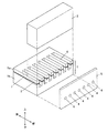
図2は上記チャネル基板1、カバープレート2及びノズルプレート5の要部構成を示す分解斜視図である。
図2に示す通り、チャネル基板1は2枚の基板1a,1bが接着部jを介して互いに接着された構成を有している。各基板1a,1bはチタン酸ジルコン酸鉛(PZT)等の圧電材料から構成されており、厚さ方向において互いに逆方向に分極されている。チャネル基板1には互いに等間隔をあけた状態で複数のチャネル3,3,…が形成されており、各チャネル3間に隔壁6が形成されている。すなわち、チャネル基板1にはチャネル3と隔壁6とが交互に形成されている。
FIG. 2 is an exploded perspective view showing the main configuration of the
As shown in FIG. 2, the
各チャネル3はチャネル基板1の中央部から前端部にかけて切り欠かれた溝であり、チャネル基板1の厚さ方向において基板1aから基板1bの中途部にかけて切り欠かれている。特に、各チャネル3は後方部分が基板1aの上部から基板1bの中途部にかけて後方から前方に向かう方向に緩やかに傾斜しており、基板1aの上方からチャネル3の内部にインクが円滑に流入するようになっている。
Each
以上の構成を具備するチャネル基板1において、各チャネル3の上方を覆うように基板1aの上部にカバープレート2が接着され、各チャネル3に吐出口4が連通するようにチャネル基板1の前端面にノズルプレート5が接着されるようになっている。
In the
図3は図1のA−A線に沿う断面図である。
図3に示す通り、各チャネル3の内壁にはアルミニウム等の金属製の電極膜7がU字状に製膜されており、各電極膜7の内壁と接着部aの下部の一部とには保護膜8が矩形状に製膜されている。各保護膜8は電極膜7を保護するものであり、絶縁性のポリ−p−キシリレンから構成されている。
FIG. 3 is a sectional view taken along line AA in FIG.
As shown in FIG. 3, an
インクジェットヘッド100では、上記の通り基板1a,1bが互いに逆方向に分極されているため、図4(a)に示す状態において各電極膜7に電圧が印加されると、図4(b)に示す通り、各隔壁6が基板1a,1bとの接着部jを中心としてく字状(又は逆く字状)に屈曲(剪断変形)するようになっている。この場合において、各チャネル3の内部容積が変化してインクに加わる圧力が変動し、当該圧力が所定値に達すると、インクが吐出口4から吐出されるようになっている。他方、各電極7に電圧が印加された図4(b)の状態において、その電圧の印加が解除されると、図4(c)に示す通り、各隔壁6がもとの状態に戻るようになっている。
In the
図1に示す通り、チャネル基板1の上方には、各チャネル3にインクを供給するためのインクチューブ10が配されている。インクチューブ10は、一方の端部がインクを貯留したタンク(図示略)に接続されており、他方の端部がマニホールド11に接続されている。マニホールド11は、インクチューブ10とチャネル基板1とをつなぐ継手として機能するものである。インクチューブ10は接着部hを介してマニホールド11に接着されており、マニホールド11は接着部e,fを介してチャネル基板1とカバープレート2とにそれぞれ接着されている。
As shown in FIG. 1, an
マニホールド11の内部には網目状を呈した金属製のフィルタ12が配されている。フィルタ12はインクから当該インク中の異物を除去するもので、接着部gを介してマニホールド11に接着されている。
A
チャネル基板1の後方にはFPC(Flexible Print Cable)20が配されている。FPC20は接着部c,iを介してチャネル基板1に接着されている。特に、接着部iは、FPC20がチャネル基板1から剥離しないように、チャネル基板1に対しFPC20を補強的に接着する部位となっている。詳しくは図示しないが、FPC20は各チャネル3に製膜された電極膜7と通電されている。
An FPC (Flexible Print Cable) 20 is disposed behind the
FPC20には接着部dを介して駆動IC(Integrated Circuit)21が接着されている。駆動IC21は、チャネル基板1の各隔壁6を剪断変形させるための電圧の発生源として機能するものであり、FPC20を通じて転送されてきた画像信号に基づき当該電圧を発生させてFPC20を通じてその電圧を各電極膜7に印加するようになっている。
A driving IC (Integrated Circuit) 21 is bonded to the
以上の構成を具備するインクジェットヘッド100では、ノズルプレート5が突出した状態でそれ以外の部位が箱状の筐体30で略覆われている。詳しくは筐体30には開口部31が形成されており、当該開口部31にチャネル基板1及びカバープレート2の前端部が嵌合している。
In the
また、インクジェットヘッド100では、各接着部a〜jを介して接着されている部材同士が互いに12ppm/Kを超える線膨張係数の差を有している(一部の部材同士のみが互いに12ppm/Kを超える線膨張係数の差を有していてもよい。)。例えば、接着部eを介して接着されているチャネル基板1とマニホールド11とを例に挙げれば、チャネル基板1の線膨張係数とマニホールド11の線膨張係数との差が12ppm/Kを超えている。
Further, in the
また、ノズルプレート5がポリイミドで構成されている場合、ノズルプレート5の線膨張係数とチャネル基板1の線膨張係数との差が12ppm/Kを超えるが、この場合において、本実施形態では、チャネル基板1のチャネル3に対しノズルプレート5の吐出口4が位置ずれした状態で接着されたり、接着部bを構成する接着剤が吐出口4に流れ込んでインクの吐出性能が低下したりすることはない。
When the
ここで、上記部材同士を接着している各接着部a〜iは下記の「接着剤」から構成されており、下記では本発明に係る当該接着剤について詳細に説明する。 Here, each adhesion part ai which adhere | attaches the said members is comprised from the following "adhesive", and the said adhesive which concerns on this invention is demonstrated in detail below.
本発明に係る接着剤は「(1)主剤」と「(2)硬化剤」との混合物であり、100重量部の主剤に対し6重量部以上の硬化剤を(好ましくは100重量部の主剤に対し8重量部以上の硬化剤を)混合したものである。 The adhesive according to the present invention is a mixture of “(1) main agent” and “(2) curing agent”, and more than 6 parts by weight of the curing agent (preferably 100 parts by weight of the main agent with respect to 100 parts by weight of the main agent). 8 parts by weight or more of the curing agent).
(1)主剤
主剤は、2官能以下の官能基を有する「(1.1)第1のエポキシ樹脂」と3官能以上の官能基を有する「(1.2)第2のエポキシ樹脂」との含有物であり、当該主剤全体のエポキシ当量が150以下のものである。
(1) Main agent The main agent is composed of “(1.1) first epoxy resin” having a functional group of two or less functions and “(1.2) second epoxy resin” having a functional group of three or more functions. The epoxy equivalent of the whole main ingredient is 150 or less.
(1.1)第1のエポキシ樹脂
第1のエポキシ樹脂は主剤中に20〜90重量%含有されるものである。当該第1のエポキシ樹脂としては、ビスフェノールF型エポキシ樹脂が適用可能であり、その具体例としては、エピコート806,807(ジャパンエポキシレジン製),RE303S−L(日本化薬社製)等が挙げられる。
(1.1) First epoxy resin The first epoxy resin is contained in the main agent in an amount of 20 to 90% by weight. As the first epoxy resin, a bisphenol F-type epoxy resin is applicable, and specific examples thereof include Epicoat 806, 807 (manufactured by Japan Epoxy Resin), RE303S-L (manufactured by Nippon Kayaku Co., Ltd.), and the like. It is done.
(1.2)第2のエポキシ樹脂
第2のエポキシ樹脂は主剤中に10〜80重量%含有されるものである。当該第2のエポキシ樹脂としては、トリグリシジル−p−アミノフェノール,テトラグリシジルジアミノジフェニルメタン,トリグリシジルイソシアヌレート,トリグリシジルウラゾール,トリグリシジルアミノクレゾール,テトラグリシジル−1,3−ジアミノメチルシクロヘキサン,グリセロールトリグリシジルエーテル等が適用可能である。
(1.2) Second epoxy resin The second epoxy resin is contained in an amount of 10 to 80% by weight in the main agent. Examples of the second epoxy resin include triglycidyl-p-aminophenol, tetraglycidyl diaminodiphenylmethane, triglycidyl isocyanurate, triglycidyl urazole, triglycidyl amino cresol, tetraglycidyl-1,3-diaminomethyl cyclohexane, glycerol tri Glycidyl ether or the like is applicable.
更に、第2のエポキシ樹脂として「ノボラックエポキシ樹脂」を適用してもよい。
ノボラックエポキシ樹脂としては、「フェノールノボラック型エポキシ樹脂」と「クレゾールノボラック型エポキシ樹脂」とが適用可能である。
フェノールノボラック型エポキシ樹脂の具体例としては、EPPN201,202(日本化薬製),エピコート154(ジャパンエポキシレジン製),DEN−438(ダウケミカル製)等が挙げられる。
クレゾールノボラック型エポキシ樹脂の具体例としては、EOCN102,103S,104S,1020,1025,1027(日本化薬製),エピコート180S(ジャパンエポキシレジン製)等が挙げられる。
Furthermore, a “novolak epoxy resin” may be applied as the second epoxy resin.
As the novolac epoxy resin, “phenol novolac type epoxy resin” and “cresol novolac type epoxy resin” are applicable.
Specific examples of the phenol novolac type epoxy resin include EPPN 201, 202 (manufactured by Nippon Kayaku), Epicoat 154 (manufactured by Japan Epoxy Resin), DEN-438 (manufactured by Dow Chemical) and the like.
Specific examples of the cresol novolac type epoxy resin include EOCN102, 103S, 104S, 1020, 1025, 1027 (manufactured by Nippon Kayaku), Epicoat 180S (manufactured by Japan Epoxy Resin) and the like.
これら第2のエポキシ樹脂の化合物中では、耐溶剤性の観点からトリグリシジル−p−アミノフェノールを適用するのが特に好ましい。 Among these compounds of the second epoxy resin, it is particularly preferable to apply triglycidyl-p-aminophenol from the viewpoint of solvent resistance.
なお、主剤の適用に際しては、上記(1.2)のいずれか1種のエポキシ樹脂と上記(1.1)のエポキシ樹脂とを組み合わせてもよいし、上記(1.2)の互いに異なる複数種のエポキシ樹脂と上記(1.1)のエポキシ樹脂とを組み合わせてもよい。 In applying the main agent, any one of the above (1.2) epoxy resins and the above (1.1) epoxy resin may be combined, or the above (1.2) different plural You may combine a seed epoxy resin and the epoxy resin of said (1.1).
(2)硬化剤
硬化剤としては、イミダゾール類(1位又は1位及び2位をアルキル基で置換したイミダゾール)が適用可能である。当該アルキル基としては、メチル基,エチル基,イソプロピル基,t−ブチル基,ヘキシル基,ドデシル基,ペンタデシル基等の分岐・直鎖アルキル基や、シクロペンチル基,シクロヘキシル基等の環状アルキル基が挙げられ、これらアルキル基には置換基が配されていてもよい。当該置換基としては、アルキル基,アルケニル基,アリール基,ヘテロ環基,ハロゲン原子,アルコキシ基,アリールオキシ基,アルコキシカルボニル基,アリールオキシカルボニル基,スルホンアミド基,スルファモイル基,ウレイド基,アシル基,アシルオキシ基,カルバモイル基,アルキルスルホニル基,アリールスルホニル基,シアノ基,ニトロ基,スルホ基,ヒドロキシル基等が挙げられる。また、1位をアルキル基で置換したイミダゾール類においては1位以外の位置に置換基が配されていてもよく、1位及び2位をアルキル基で置換したイミダゾール類においては1位及び2位以外の位置に置換基が配されていてもよく、当該置換基としては上記アルキル基に配される置換基として挙げられたものが適用可能である。
(2) Curing agent As the curing agent, imidazoles (imidazole in which 1-position or 1-position and 2-position are substituted with an alkyl group) can be applied. Examples of the alkyl group include branched and straight chain alkyl groups such as methyl group, ethyl group, isopropyl group, t-butyl group, hexyl group, dodecyl group, and pentadecyl group, and cyclic alkyl groups such as cyclopentyl group and cyclohexyl group. These alkyl groups may have a substituent. Examples of the substituent include alkyl groups, alkenyl groups, aryl groups, heterocyclic groups, halogen atoms, alkoxy groups, aryloxy groups, alkoxycarbonyl groups, aryloxycarbonyl groups, sulfonamido groups, sulfamoyl groups, ureido groups, and acyl groups. , Acyloxy group, carbamoyl group, alkylsulfonyl group, arylsulfonyl group, cyano group, nitro group, sulfo group, hydroxyl group and the like. In the imidazoles substituted at the 1-position with an alkyl group, a substituent may be arranged at positions other than the 1-position, and in the imidazoles substituted at the 1-position and the 2-position with an alkyl group, the 1-position and the 2-position. Substituents may be arranged at positions other than the above, and as the substituent, those exemplified as the substituents arranged on the alkyl group can be applied.
1位又は1位及び2位をアルキル基で置換したイミダゾールの具体例としては、1−メチルイミダゾール,1−ベンジル−2−メチルイミダゾール,1,2−ジメチルイミダゾール,1−イソブチル−2−メチルイミダゾール,1−メチル−2−エチルイミダゾール,1−エチルイミダゾール,1−シアノエチル−2−エチル−4−メチルイミダゾール,1−シアノエチル−2−メチルイミダゾール,1−(2−ヒドロキシ−3−フェノキシプロピル)−2−エチル−4−メチルイミダゾール,1−(2−ヒドロキシ−3−フェノキシプロピル)−2−メチルイミダゾール等が挙げられる。 Specific examples of imidazole substituted at the 1-position or 1-position and 2-position with an alkyl group include 1-methylimidazole, 1-benzyl-2-methylimidazole, 1,2-dimethylimidazole, 1-isobutyl-2-methylimidazole. 1-methyl-2-ethylimidazole, 1-ethylimidazole, 1-cyanoethyl-2-ethyl-4-methylimidazole, 1-cyanoethyl-2-methylimidazole, 1- (2-hydroxy-3-phenoxypropyl)- Examples include 2-ethyl-4-methylimidazole and 1- (2-hydroxy-3-phenoxypropyl) -2-methylimidazole.
硬化後の上記接着剤からは、熱分解GCマススペクトルによりイミダゾール環含有化合物と、3つ以上のエポキシ基を有する化合物がそのエポキシ基が脱離した形で検出される。また固体NMRによりイミダゾール環含有化合物が検出される。 From the cured adhesive, the imidazole ring-containing compound and the compound having three or more epoxy groups are detected in a form in which the epoxy group is eliminated by thermal decomposition GC mass spectrum. Moreover, an imidazole ring containing compound is detected by solid state NMR.
なお、本発明に係る接着剤には、添加剤として「(3)樹脂微粒子」,「(4)シランカップリング剤」,「(5)ジルコネート」が添加されてもよい。これら添加剤は単独で添加されてもよいし、2種以上の添加剤が同時に添加されてもよい。 The adhesive according to the present invention may contain “(3) resin fine particles”, “(4) silane coupling agent”, and “(5) zirconate” as additives. These additives may be added alone, or two or more additives may be added simultaneously.
(3)樹脂微粒子
樹脂微粒子としては、メチルメタアクリレートとブチルアクリレートとの共重合体等の粒子が適用可能である。
(3) Resin fine particles As the resin fine particles, particles such as a copolymer of methyl methacrylate and butyl acrylate are applicable.
(4)シランカップリング剤
シランカップリング剤としては、γ−アミノプロピルトリエトキシシラン,N−β−アミノエチル−γ−アミノプロピルトリエトキシシラン,N−β−アミノエチル−γ−アミノプロピルトリメトキシシラン,N−β−アミノエチル−γ−アミノプロピルメチルジメトキシシラン,N−フェニル−γ−アミノプロピルトリメトキシシラン,γ−ユレイドプロピルトリエトキシシラン等のアミノシランカップリング剤や、γ−グリシドキシプロピルトリメトキシシラン,β−(3,4−エポキシシクロヘキシル)エチルトリメトキシシラン,γ−グリシドキシプロピルメチルジエトキシシラン等のエポキシシランカップリング剤が適用可能である。
(4) Silane coupling agent As the silane coupling agent, γ-aminopropyltriethoxysilane, N-β-aminoethyl-γ-aminopropyltriethoxysilane, N-β-aminoethyl-γ-aminopropyltrimethoxy Aminosilane coupling agents such as silane, N-β-aminoethyl-γ-aminopropylmethyldimethoxysilane, N-phenyl-γ-aminopropyltrimethoxysilane, γ-ureidopropyltriethoxysilane, and γ-glycidoxy Epoxysilane coupling agents such as propyltrimethoxysilane, β- (3,4-epoxycyclohexyl) ethyltrimethoxysilane, and γ-glycidoxypropylmethyldiethoxysilane are applicable.
(5)ジルコネート
ジルコネートとしては、ネオペンチル(ジアリル)オキシトリネオデカノイルジルコネート,ネオペンチル(ジアリル)オキシトリ(ドデシル)ベンゼン−スルホニルジルコネート,ネオペンチル(ジアリル)オキシ・トリ(p−アミノ)ベンゾエート・ジルコネート(LZ−37),テトラプロピルジルコネート,テトラブチルジルコネート,テトラ(エタノールアミン)ジルコネート,テトライソプロピルジルコネート,イソプロピルトリ(n−アミノエチル−アミノエチル)ジルコネート,ジイソプロピルジ(4−アミノベンゾイル)ジルコネート,トリス−2−プロポキシ(2−エチルアミノ)エチルジルコネート,トリス[(2,2−ビス2−プロペニルオキシメチル)ブトキシ]エチレンジアミノエトキシジルコネート等が適用可能である。
(5) Zirconate As the zirconate, neopentyl (diallyl) oxytrineodecanoyl zirconate, neopentyl (diallyl) oxytri (dodecyl) benzene-sulfonyl zirconate, neopentyl (diallyl) oxy tri (p-amino) benzoate zirconate ( LZ-37), tetrapropylzirconate, tetrabutylzirconate, tetra (ethanolamine) zirconate, tetraisopropylzirconate, isopropyltri (n-aminoethyl-aminoethyl) zirconate, diisopropyldi (4-aminobenzoyl) zirconate, Tris-2-propoxy (2-ethylamino) ethyl zirconate, tris [(2,2-bis-2-propenyloxymethyl) butoxy] ethylenediaminoethoxydi Luconate is applicable.
また、インクジェットヘッド100から吐出される「インク」は、染料,顔料などの色材やそれを溶解させる溶媒(溶剤)などから構成されているもので、その種類は特には限定しないが、SP(Solubility Parameter)値((cal/cm)1/2)が9.5〜15.0でかつ双極子能率が2.0〜5.0である溶媒を全溶媒に対し3重量%以上含有しているものであることが印刷画像の定着性の点から好ましく、本実施形態によれば、このようなインクに対して耐久性が劣化しないという特徴を有する。当該溶媒の具体例としては、N,N−ジメチルホルムアミド(SP値=12.1,双極子能率=3.86),N−メチル−2−ピロリジノン(SP値=11.3,双極子能率=4.09),乳酸エチル(SP値=10.0,双極子能率=2.14),シクロヘキサノン(SP値=9.9,双極子能率=3.01),2−ピロリジノン(SP値=14.7,双極子能率=3.83)などが挙げられる。
The “ink” ejected from the
なお、ここでの双極子能率はMOPACのAM1により算出したもので、SP値はBicerano法により算出したものである。「Bicerano法」はPrediction of Polymer Properties (Plastics Engineering, 65)Jozef Bicerano (著)に記載されている。 Here, the dipole efficiency is calculated by MOPAC AM1, and the SP value is calculated by the Bicerano method. The “Bicerano method” is described in Prediction of Polymer Properties (Plastics Engineering, 65) Jozef Bicerano (Author).
続いて、本発明に係る「インクジェットヘッド100の製造方法」について説明する。
Next, the “method for manufacturing the
始めに、平板状の2枚の基板1a,1bに対し上記接着剤を塗布して各基板1a,1bを貼り合わせ(接着部jを形成し)、当該接着部jに60℃(好ましくは40℃)以下の熱を加えて当該接着部jを硬化させ、各基板1a,1bを接着する。各基板1a,1bを接着してチャネル基板1を製造したら、チャネル基板1に対しダイシングブレード等を用いて複数のチャネル3,3,…を形成し、各チャネル3の内壁に対し公知の蒸着処理を施して各チャネル3の内部に電極膜7を製膜する。
First, the adhesive is applied to the two
各チャネル3の内壁に電極膜7を製膜したら、チャネル基板1の基板1aの上部に上記接着剤を塗布してカバープレート2を貼り合わせ(接着部aを形成し)、当該接着部aに60℃(好ましくは40℃)以下の熱を加えて当該接着部aを硬化させ、図5(a),(b)に示す通り、基板1aの上部にカバープレート2を接着する(図5(b)は図5(a)中B−B線に沿う断面図であり、図5(a)〜(c)中には各接着部a,j及び電極膜7は図示されていない。)
After the
カバープレート2を接着したら、電極膜7の内壁に対しCVD(Chemical Vapor Deposition)法でポリ−p−キシリレン処理を施して、各チャネル3の内部に保護膜8を製膜する。保護膜8を製膜したら、図5(c)に示す通り、各チャネル3の長さ方向に対し直交する方向に沿ってチャネル基板1とカバープレート2との中央部を切断し(2分割し)、2片のヘッドチップ101,101を製造する(図5(c)中には電極膜7及び保護膜8は図示されていない。)。
When the
ヘッドチップ101を製造したら、チャネル基板1とカバープレート2との各端面に上記接着剤を塗布し、各吐出口4がチャネル3に連通するようにそれら各端面に対しノズルプレート5を貼り合わせ(接着部bを形成し)、当該接着部bに60℃(好ましくは40℃)以下の熱を加えて当該接着部bを硬化させ、チャネル基板1とカバープレート2との各端面にノズルプレート5を接着する。
After the
ノズルプレート5を接着したら、インクジェットヘッド100を構成する上記以外のマニホールド11,FPC20,筐体30等の部材に接着剤を塗布し、ヘッドチップ101の所定位置にこれら部材を貼り合わせ(接着部c〜jを形成し)、各接着部c〜iに60℃(好ましくは40℃)以下の熱を加えて各接着部c〜iを硬化させ、これら部材とヘッドチップ101とを接着する。以上の工程の処理を経ることにより、本発明に係るインクジェットヘッド100を製造することができる。
After the
なお、本実施形態では、各接着部a〜jを形成するごとに各接着部a〜jに熱を加えて各接着部a〜jを硬化させたが、各接着部a〜jを全て形成して(部材同士を全て貼り合せて)から全接着部a〜jに同時に熱を加えて全接着部a〜jを一度に硬化させてもよい。 In this embodiment, each time the adhesive portions aj are formed, the adhesive portions aj are heated to cure the adhesive portions aj, but all the adhesive portions aj are formed. Then, all the bonded portions a to j may be cured at once by applying heat to all the bonded portions a to j after bonding all the members together.
続いて、インクジェットヘッド100の動作・作用について説明する。
Next, the operation / action of the
インクチューブ10を通じてインクタンク(図示略)からインクチューブ10を経てマニホールド11にインクを流入させると、当該インクはフィルタ12を通じて異物が除去され、マニホールド11と各チャネル3との内部に貯留される(図1中矢印参照)。
When ink flows from the ink tank (not shown) through the
この状態において、FPC20を通じて画像信号が駆動IC21に転送されると、駆動IC21が、当該画像信号に基づいてチャネル基板1の各隔壁6を剪断変形させるための駆動電圧を発生させ、FPC20を通じてその駆動電圧を各電極膜7に印加する。
In this state, when the image signal is transferred to the
各電極膜7が駆動電圧の印加を受けると、各隔壁6が基板1a,1bの接着部jを中心としてく字状又は逆く字状に剪断変形し(図4(a)に示す状態から図4(b)に示す状態に移行し)、各チャネル3の内部容積が変化してインクに加わる圧力が変動する。そして当該圧力が所定値に達したときに、インクジェットヘッド100が吐出口4からインクを滴として吐出する。
When each
以上の本実施形態では、各接着部a〜jが上記接着剤で構成され、かつ、インクジェットヘッド100を製造する際に各接着部a〜jに60℃以下の熱を加えて硬化させているため、硬化後の各接着部a〜jとそれにより接着される部材との間(例えば、接着部aとチャネル基板1又はカバープレート2との間)に作用する応力が緩和される。
In the above embodiment, each adhesive part aj is comprised with the said adhesive agent, and at the time of manufacturing the
すなわち、接着剤とそれにより接着される被接着部材との間で発生する「応力P」は下記式(A)で求められる。
P≒EΔα(t2−t1) … (A)
式(A)中、E:接着剤の弾性率,Δα:接着剤と被接着部材との間の線膨張係数の差,t2:硬化温度(接着剤に加える熱の温度),t1:室温
That is, the “stress P” generated between the adhesive and the adherend to be bonded is obtained by the following formula (A).
P≈EΔα (t 2 −t 1 ) (A)
In the formula (A), E: elastic modulus of the adhesive, Δα: difference in linear expansion coefficient between the adhesive and the member to be bonded, t 2 : curing temperature (temperature of heat applied to the adhesive), t 1 : room temperature
上記式(A)を元に、例えば、接着部aの弾性率を3430MPaと、チャネル基板1の線膨張係数を2×10⁻⁶/℃と、接着部aの線膨張係数を8×10−5/℃と想定し、接着部aに対し「100℃」の熱を加えて接着部aを硬化させた場合においては、接着部aが室温(25℃)に戻るときに発生する応力は20.07MPaと算出され、20MPa程度の応力が接着部aとチャネル基板1との間に発生する。この場合において、チャネル基板1には撓みが生じてチャネル基板1そのものの内部に圧縮ストレスが掛かり、その結果、チャネル基板1を部分的に脱分極させてしまい、インクの吐出変動を引き起こすと考えられる。
Based on the above formula (A), for example, the elastic modulus of the bonded portion a is 3430 MPa, the linear expansion coefficient of the
しかしながら、本実施形態のように、接着部aに対し60℃の熱を加えて接着部aを硬化させた場合には、接着部aが室温(25℃)に戻るときに発生する応力は9.3MPaと算出され、接着部aとチャネル基板1との間に発生する応力が略半減し、接着部aとチャネル基板1との間に作用する応力が緩和される。
However, when the adhesive part a is cured by applying 60 ° C. heat to the adhesive part a as in this embodiment, the stress generated when the adhesive part a returns to room temperature (25 ° C.) is 9 .3 MPa, the stress generated between the bonded portion a and the
以上から、硬化後の各接着部a〜jと、チャネル基板1、チャネル基板1に接着される被接着部材(カバープレート2、ノズルプレート5、マニホールド11等)又は当該被接着部材に接着される第2の被接着部材(マニホールド11、インクチューブ10、フィルタ12等)との間に作用する応力が緩和され、インクジェットヘッド1を構成する各部材にひび割れが発生したり、それら各部材が歪んだり、一方の部材から他方の部材が剥がれ落ちたりするのを防止することができる。
From the above, each of the bonded portions a to j after curing is bonded to the
特に、マニホールド11が熱可塑性樹脂で成形される場合には、その成形が容易ではあるが、当該マニホールド11は線膨張係数が大きくてチャネル基板1やカバープレート2との間において線膨張係数の差が12ppm/Kを超え易く、更に、断面積が大きいためにチャネル基板1やカバープレート2から受ける応力が大きい(逆に、チャネル基板1やカバープレート2も当該マニホールド11から受ける応力が大きい。)。そのため、この場合には、チャネル基板1、カバープレート2及びマニホールド11はひび割れ、歪み、剥離等を生じやすいが、本実施形態ではこれら部材が上記接着剤で接着されているから、当該部材のひび割れ、歪み、剥離等を有効に防止することができる。
In particular, when the manifold 11 is molded from a thermoplastic resin, the molding is easy, but the manifold 11 has a large linear expansion coefficient, and the difference in linear expansion coefficient between the
(参考例)
(1.1)試料1〜13の作製
主剤と硬化剤とを混合(任意に樹脂微粒子、シランカップリング剤及びジルコネートも混合)し、その混合物を1粒当たり0.1〜0.2gの粒状物としてテフロン(登録商標)シート上に滴下した。その後、滴下した各粒状物を45℃で10時間放置して硬化させ、接着剤の錠剤を作製し、これらを「試料1〜13」とした。各試料1〜13の組成(主剤、硬化剤、樹脂微粒子、シランカップリング剤及びジルコネートの有無とその種類)は下記表1に示す通りである。
(Reference example)
(1.1) Preparation of
(1.2)試料1〜13の質量増加率の測定
試料1〜13の作製後、各試料1〜13の質量を測定し、各試料1〜13を溶剤(N−メチルピロリドン)中に浸漬させて60℃で7日間放置した。7日間経過後、各試料1〜13を溶剤から取り出して洗瓶のイソプロピルアルコールで洗浄した。洗浄後、各試料1〜13の表面に付着したイソプロピルアルコールを除去し、各試料1〜13の質量を再度測定した。
(1.2) Measurement of mass increase rate of
再度の質量測定後、各試料1〜13の質量増加率を下記式に従って算出した。算出結果は下記表1に示す通りである。
質量増加率(%)=(((溶剤浸漬後の質量)−(溶剤浸漬前の質量))/(溶剤浸漬前の質量))×100
The mass increase rate of each sample 1-13 was computed according to the following formula after the mass measurement again. The calculation results are as shown in Table 1 below.
Mass increase rate (%) = (((mass after solvent immersion) − (mass before solvent immersion)) / (mass before solvent immersion)) × 100

なお、表1「主剤」の項目中、「E1」はビスフェノールA型エポキシ樹脂(2官能,エピコート828(ジャパンエポキシレジン製),184〜194g/eq)であり、「E2」はビスフェノールF型エポキシ樹脂(2官能,エピコート806(ジャパンエポキシレジン製),160〜170g/eq)であり、「E3」はフェノールノボラック型エポキシ樹脂(3官能以上,エピコート152(ジャパンエポキシレジン製))であり、「E4」はトリグリシジル−p−アミノフェノールであり、「E5」はテトラグリシジルジアミノジフェニルメタンであり、括弧内の数字は主剤を構成する各化合物の重量(重量部)を示す。 In Table 1, “Main Agent”, “E1” is a bisphenol A type epoxy resin (bifunctional, Epicoat 828 (manufactured by Japan Epoxy Resin), 184 to 194 g / eq), and “E2” is a bisphenol F type epoxy. Resin (bifunctional, Epicoat 806 (manufactured by Japan Epoxy Resin), 160 to 170 g / eq), and “E3” is a phenol novolac type epoxy resin (trifunctional or more, Epicote 152 (manufactured by Japan Epoxy Resin)). “E4” is triglycidyl-p-aminophenol, “E5” is tetraglycidyldiaminodiphenylmethane, and the numbers in parentheses indicate the weight (parts by weight) of each compound constituting the main agent.
表1「硬化剤」の項目中、「Z1」は2−エチル−4−メチルイミダゾールであり、「Z3」は1−ベンジル−2−メチルイミダゾールであり、「Z4」は2,4−ジメチルイミダゾールであり、「H3」はトリエチレンテトラミンであり、括弧内の数字は主剤100重量部に対するその硬化剤の重量部を示す。 In the item of Table 1 “Curing agent”, “Z1” is 2-ethyl-4-methylimidazole, “Z3” is 1-benzyl-2-methylimidazole, and “Z4” is 2,4-dimethylimidazole. "H3" is triethylenetetramine, and the numbers in parentheses indicate parts by weight of the curing agent with respect to 100 parts by weight of the main agent.
表1「樹脂微粒子」,「シランカップリング剤」,「ジルコネート」の項目中、「A」はメチルメタアクリレートとブチルアクリレートの共重合体粒子(平均粒子径約0.3μm)であり、「B」はγ−グリシドキシプロピルトリメトキシシランであり、「C」はイソプロピルトリ(n−アミノエチル−アミノエチル)ジルコネートであり、括弧内の数字は主剤100重量部に対するその添加剤の重量部を示す。 In Table 1, “resin fine particles”, “silane coupling agent”, and “zirconate”, “A” is a copolymer particle of methyl methacrylate and butyl acrylate (average particle diameter of about 0.3 μm), and “B” ”Is γ-glycidoxypropyltrimethoxysilane,“ C ”is isopropyltri (n-aminoethyl-aminoethyl) zirconate, and the numbers in parentheses are parts by weight of the additive with respect to 100 parts by weight of the main agent. Show.
(1.3)結び
表1に示す通り、試料1〜6,13はそれ以外の試料7〜12に比較して重量変化率が極めて低く、試料1〜6,13が溶剤に溶解されにくいことがわかる。以上から、試料1〜6,13のような特定組成の接着剤は、60℃以下の低温で硬化して溶剤に対しても耐性を有することがわかる。
(1.3) Conclusion As shown in Table 1, the
(2.1)試料1〜13の作製
「第1のPZT基板(厚さ150μm,キューリー温度210℃,線膨張係数4ppm/K)」と「第2のPZT基板(厚さ700μm,キューリー温度210℃,線膨張係数4ppm/K)」との2枚のPZT基板を準備して、これら第1,第2の各PZT基板を分極方向が反対向きになるように接着剤で接着した。第1のPZT基板と第2のPZT基板との接着に際しては、接着剤としてエポテック353ND((株)理経製)を使用し、当該接着剤に80〜100℃の熱を加えて当該接着剤を硬化させた。
(2.1) Production of
第1,第2の各PZT基板を接着したら、第1のPZT基板から第2のPZT基板に向けて深さ300μm,幅70μmのチャネル(溝)を形成し、当該チャネルの内壁にアルミニウムを蒸着してチャネルの内部にアルミニウム製の電極膜を製膜した。 After bonding the first and second PZT substrates, a channel (groove) having a depth of 300 μm and a width of 70 μm is formed from the first PZT substrate to the second PZT substrate, and aluminum is deposited on the inner walls of the channels. Then, an electrode film made of aluminum was formed inside the channel.
電極膜を製膜したら、カバープレート(厚さ700μmの窒化アルミニウム,線膨張係数4ppm/K)を第1のPZT基板上に接着剤で接着した(図5(a),(b)参照)。カバープレートと第1のPZT基板との接着に際しては、接着剤としてエポテック353ND((株)理経製)を使用し、当該接着剤に80〜100℃の熱を加えて当該接着剤を硬化させた。
When the electrode film was formed, a cover plate (aluminum nitride having a thickness of 700 μm,
カバープレートを接着したら、電極膜の内壁に対しCVD法によるポリ−p−キシリレン処理を施してチャネルの内部に保護膜を製膜した。保護膜を製膜したら、チャネルの長さ方向と直交する方向に沿って第1,第2の各PZT基板及びカバープレートを切断し、ヘッドチップを製造した(図5(c)参照)。 After the cover plate was bonded, the inner wall of the electrode film was subjected to poly-p-xylylene treatment by CVD to form a protective film inside the channel. When the protective film was formed, the first and second PZT substrates and the cover plate were cut along a direction orthogonal to the length direction of the channel to manufacture a head chip (see FIG. 5C).
ヘッドチップを製造したら、そのヘッドチップに対しノズルプレート(厚さ100μmのポリイミドに直径30μmの吐出口を形成したもの)を接着剤で接着した。カバープレートとヘッドチップ(第1のPZT基板)との接着に際しては、接着剤としてエポテック353ND((株)理経製)を使用し、当該接着剤に80〜100℃の熱を加えて当該接着剤を硬化させた。 When the head chip was manufactured, a nozzle plate (a polyimide having a thickness of 100 μm formed with a discharge port having a diameter of 30 μm) was bonded to the head chip with an adhesive. When bonding the cover plate and the head chip (first PZT substrate), Epotec 353ND (manufactured by Rikei Co., Ltd.) is used as an adhesive, and heat is applied to the adhesive at 80 to 100 ° C. Was cured.
ノズルプレートを接着したら、マニホールド(ポリアミド製,線膨張係数50ppm/K)等の他の部材をヘッドチップに接着剤で接着し、インクジェットヘッドを製造した。本実施例2では、マニホールドの接着(マニホールドとカバープレートとの接着及びマニホールドと第1のPZT基板との接着)において、下記表2に示す13種類の接着剤を適用し、それら各接着剤に40℃の熱を17時間加えて当該各接着剤を硬化させた。そして、それら接着剤の種類に応じた合計13種類のインクジェットヘッドを製造し、これらインクジェットヘッドを「試料1〜13」とした。
After the nozzle plate was bonded, another member such as a manifold (made of polyamide, linear expansion coefficient 50 ppm / K) was bonded to the head chip with an adhesive to manufacture an inkjet head. In Example 2, 13 types of adhesives shown in Table 2 below were applied to the manifolds (adhesion between the manifold and the cover plate and adhesion between the manifold and the first PZT substrate). Each adhesive was cured by applying heat at 40 ° C. for 17 hours. And a total of 13 types of inkjet heads according to the types of these adhesives were manufactured, and these inkjet heads were designated as “
(2.2)各試料1〜13の評価
(2.2.1)吐出試験
インクの代替物としてブトキシエチルアセテート90重量部と2−ピロリジノン10重量部との混合物を適用し、各試料1〜13から当該混合物を吐出し続け、各試料1〜13の吐出性能(いつインクの漏れが発生したか)を評価した。評価結果を下記表2に示す。
(2.2) Evaluation of
(2.2.2)ヒートサイクル試験
1回目のヒートサイクル試験として、25℃→(60℃,1時間)→(25℃,30分)→(0℃,1時間)→(25℃,30分)を1サイクルとした3サイクル分のヒートサイクル環境に各試料1〜13を供し、各試料1〜13のチャネルを減圧して当該チャネルに空気漏れがあるか否かを確認した。
(2.2.2) Heat cycle test As the first heat cycle test, 25 ° C. → (60 ° C., 1 hour) → (25 ° C., 30 minutes) → (0 ° C., 1 hour) → (25 ° C., 30 Each
その後更に、2回目のヒートサイクル試験として、25℃→(60℃,1時間)→(25℃,30分)→(−20℃,1時間)→(25℃,30分)を1サイクルとした3サイクル分のヒートサイクル環境に各試料1〜13を供し、各試料1〜13のチャネルを減圧して当該チャネルに空気漏れがあるか否かを確認した。 Thereafter, as the second heat cycle test, 25 ° C. → (60 ° C., 1 hour) → (25 ° C., 30 minutes) → (−20 ° C., 1 hour) → (25 ° C., 30 minutes) is one cycle. Each sample 1-13 was used for the heat cycle environment for 3 cycles, and the channel of each sample 1-13 was pressure-reduced, and it was confirmed whether there was an air leak in the said channel.
試験結果を下記表2に示す。表2「ヒートサイクル試験」の項目中、◎,○,△,×の各基準は下記の通りである。
◎…1,2回目の両ヒートサイクル試験で空気漏れが無かった
○…1回目のヒートサイクル試験では空気漏れは無かったが2回目のヒートサイクル試験で空気漏れが発生した
△…1回目のヒートサイクル試験で若干の空気漏れが発生した
×…1回目のヒートサイクル試験で空気漏れが発生した
The test results are shown in Table 2 below. In the items of Table 2 “Heat cycle test”, the standards of ◎, ○, Δ, and × are as follows.
◎… There was no air leak in both the first and second heat cycle tests ○… There was no air leak in the first heat cycle test, but there was an air leak in the second heat cycle test △… The first heat Some air leaks occurred in the cycle test ×… Air leaks occurred in the first heat cycle test
(2.2.3)ひび割れの有無の観察
上記ヒートサイクル試験後において、カバープレートとマニホールドとの間の接着剤にひび割れがあるか否かを各試料1〜13ごとに目視により観察した。観察結果を下記表2に示す。表2「ひび割れ」の項目中、○,△,×の各基準は下記の通りである。
○…ひび割れは無かった
△…1〜2箇所のひび割れが認められた
×…3箇所以上のひび割れが認められた
(2.2.3) Observation of presence or absence of cracks After the heat cycle test, whether or not the adhesive between the cover plate and the manifold is cracked was visually observed for each of the
○… No cracks △… One or two cracks were observed ×… 3 or more cracks were observed
なお、表2「主剤」,「硬化剤」,「樹脂微粒子」,「シランカップリング剤」,「ジルコネート」の各項目中の種類や括弧内の数字等は参考例の表1と同様である。 Table 2 “Main agent”, “Curing agent”, “Resin fine particle”, “Silane coupling agent”, “Zirconate” in each item, the numbers in parentheses, etc. are the same as in Table 1 of the reference example. .
(2.3)結び
表2に示す通り、試料1〜6はそれ以外の試料7〜12に比較して結果が良好であり、特に、吐出試験及びヒートサイクル試験の結果から、本発明のインクジェットヘッドは、インク漏れや空気漏れが発生せず、接着剤のひび割れも発生しないことが分かる。また本発明のインクジェットヘッドでは、空気漏れが発生しなかったことから、マニホールド等の部材においてひび割れ、歪み、剥離等がないことがわかる。以上から、試料1〜6のインクジェットヘッドは、接着剤が60℃以下の熱で硬化され、優れた性能を有することが分かる。
(2.3) Conclusion As shown in Table 2, the results of
100 インクジェットヘッド
101 ヘッドチップ
a〜j 接着部
1 チャネル基板
2 カバープレート(被接着部材)
3 チャネル
4 吐出口
5 ノズルプレート(被接着部材)
6 隔壁
7 電極膜
8 保護膜
10 インクチューブ(第2の被接着部材)
11 マニホールド(被接着部材,第2の被接着部材)
12 フィルタ(第2の被接着部材)
20 FPC(被接着部材)
21 駆動IC(第2の被接着部材)
30 筐体
DESCRIPTION OF
3
6
11 Manifold (Adhered member, Second Adhered member)
12 Filter (second adherend)
20 FPC (Adhered member)
21 Drive IC (second adherend)
30 housing
Claims (6)
前記チャネル基板と前記被接着部材とが、又は前記被接着部材と前記第2の被接着部材とが、下記接着剤で接着され、 The channel substrate and the adherend member, or the adherend member and the second adherend member are bonded with the following adhesive,
前記接着剤が、主剤と硬化剤とが混合された接着剤であって、 The adhesive is an adhesive in which a main agent and a curing agent are mixed,
前記主剤が、2官能以下の官能基を有する第1のエポキシ樹脂と3官能以上の官能基を有する第2のエポキシ樹脂とを含有し、前記第1のエポキシ樹脂が当該主剤中に20〜90重量%含有されかつ前記第2のエポキシ樹脂が当該主剤中に10〜80重量%含有されており、 The main agent contains a first epoxy resin having a bifunctional or lower functional group and a second epoxy resin having a trifunctional or higher functional group, and the first epoxy resin is 20 to 90 in the main agent. And the second epoxy resin is contained in an amount of 10 to 80% by weight in the main agent,
前記硬化剤がイミダゾール類であり、 The curing agent is an imidazole,
100重量部の前記主剤に対し6重量部以上の前記硬化剤が混合され、かつ、前記第1のエポキシ樹脂がビスフェノールF型エポキシ樹脂であることを特徴とするインクジェットヘッド。 An inkjet head, wherein 6 parts by weight or more of the curing agent is mixed with 100 parts by weight of the main agent, and the first epoxy resin is a bisphenol F-type epoxy resin.
前記チャネル基板と前記被接着部材とが、又は前記被接着部材と前記第2の被接着部材とが、下記接着剤で接着され、
前記接着剤が、主剤と硬化剤とが混合された接着剤であって、
前記主剤が、2官能以下の官能基を有する第1のエポキシ樹脂と3官能以上の官能基を有する第2のエポキシ樹脂とを含有し、前記第1のエポキシ樹脂が当該主剤中に20〜90重量%含有されかつ前記第2のエポキシ樹脂が当該主剤中に10〜80重量%含有されており、
前記硬化剤がイミダゾール類であり、
100重量部の前記主剤に対し6重量部以上の前記硬化剤が混合され、かつ、シランカップリング剤が添加されていることを特徴とするインクジェットヘッド。 An ink-jet head comprising: a channel substrate having an ink channel; a member to be bonded to the channel substrate; and a second member to be bonded to the member to be bonded.
The channel substrate and the adherend member, or the adherend member and the second adherend member are bonded with the following adhesive,
The adhesive is an adhesive in which a main agent and a curing agent are mixed,
The main agent contains a first epoxy resin having a bifunctional or lower functional group and a second epoxy resin having a trifunctional or higher functional group, and the first epoxy resin is 20 to 90 in the main agent. And the second epoxy resin is contained in an amount of 10 to 80% by weight in the main agent,
The curing agent is an imidazole,
An ink jet head, wherein 6 parts by weight or more of the curing agent is mixed with 100 parts by weight of the main agent, and a silane coupling agent is added .
前記チャネル基板と前記被接着部材との間に、又は前記被接着部材と前記第2の被接着部材との間に、前記接着剤を塗布し、該接着剤に60℃以下の熱を加えて該接着剤を硬化させ、前記チャネル基板と前記被接着部材とを、又は前記被接着部材と前記第2の被接着部材とを接着することを特徴とするインクジェットヘッドの製造方法。 The adhesive is applied between the channel substrate and the adherend member, or between the adherend member and the second adherend member, and heat of 60 ° C. or less is applied to the adhesive. A method of manufacturing an ink jet head, comprising: curing the adhesive; and bonding the channel substrate and the member to be bonded, or bonding the member to be bonded and the second member to be bonded.
前記チャネル基板と前記被接着部材との間に、又は前記被接着部材と前記第2の被接着部材との間に、前記接着剤を塗布し、該接着剤に60℃以下の熱を加えて該接着剤を硬化させ、前記チャネル基板と前記被接着部材とを、又は前記被接着部材と前記第2の被接着部材とを接着することを特徴とするインクジェットヘッドの製造方法。The adhesive is applied between the channel substrate and the adherend member, or between the adherend member and the second adherend member, and heat of 60 ° C. or less is applied to the adhesive. A method of manufacturing an ink jet head, comprising: curing the adhesive; and bonding the channel substrate and the member to be bonded, or bonding the member to be bonded and the second member to be bonded.
Priority Applications (3)
| Application Number | Priority Date | Filing Date | Title |
|---|---|---|---|
| JP2006036571A JP4987318B2 (en) | 2005-03-18 | 2006-02-14 | Ink jet head and manufacturing method thereof |
| US11/384,091 US20060207720A1 (en) | 2005-03-18 | 2006-03-17 | Manufacturing method of inkjet head, and adhesive agent composition |
| US12/584,616 US7922860B2 (en) | 2005-03-18 | 2009-09-09 | Manufacturing inkjet head by adhering with epoxy resins and alkyl imidazole |
Applications Claiming Priority (5)
| Application Number | Priority Date | Filing Date | Title |
|---|---|---|---|
| JP2005079570 | 2005-03-18 | ||
| JP2005079570 | 2005-03-18 | ||
| JP2005364691 | 2005-12-19 | ||
| JP2005364691 | 2005-12-19 | ||
| JP2006036571A JP4987318B2 (en) | 2005-03-18 | 2006-02-14 | Ink jet head and manufacturing method thereof |
Related Child Applications (1)
| Application Number | Title | Priority Date | Filing Date |
|---|---|---|---|
| JP2012014290A Division JP5535248B2 (en) | 2005-03-18 | 2012-01-26 | Ink jet head and manufacturing method thereof |
Publications (2)
| Publication Number | Publication Date |
|---|---|
| JP2007191669A JP2007191669A (en) | 2007-08-02 |
| JP4987318B2 true JP4987318B2 (en) | 2012-07-25 |
Family
ID=38447621
Family Applications (1)
| Application Number | Title | Priority Date | Filing Date |
|---|---|---|---|
| JP2006036571A Active JP4987318B2 (en) | 2005-03-18 | 2006-02-14 | Ink jet head and manufacturing method thereof |
Country Status (1)
| Country | Link |
|---|---|
| JP (1) | JP4987318B2 (en) |
Families Citing this family (3)
| Publication number | Priority date | Publication date | Assignee | Title |
|---|---|---|---|---|
| JP5372054B2 (en) * | 2011-03-11 | 2013-12-18 | 東芝テック株式会社 | Inkjet head |
| JP2012187864A (en) * | 2011-03-11 | 2012-10-04 | Toshiba Tec Corp | Inkjet head |
| WO2023042336A1 (en) * | 2021-09-16 | 2023-03-23 | コニカミノルタ株式会社 | Ink ejection device |
Family Cites Families (3)
| Publication number | Priority date | Publication date | Assignee | Title |
|---|---|---|---|---|
| JP4037603B2 (en) * | 2000-11-24 | 2008-01-23 | 株式会社リコー | Epoxy resin composition and method of manufacturing ink jet head using the same |
| JP5111695B2 (en) * | 2001-04-03 | 2013-01-09 | 株式会社リコー | Epoxy resin composition for manufacturing inkjet head and method for manufacturing inkjet head |
| JP2003176460A (en) * | 2001-10-01 | 2003-06-24 | Nippon Sheet Glass Co Ltd | Method for joining optical part and primer composition |
-
2006
- 2006-02-14 JP JP2006036571A patent/JP4987318B2/en active Active
Also Published As
| Publication number | Publication date |
|---|---|
| JP2007191669A (en) | 2007-08-02 |
Similar Documents
| Publication | Publication Date | Title |
|---|---|---|
| JP4987286B2 (en) | Ink jet head and method of manufacturing ink jet head | |
| US7922860B2 (en) | Manufacturing inkjet head by adhering with epoxy resins and alkyl imidazole | |
| JP4804774B2 (en) | Adhesive composition, inkjet head, and method of manufacturing inkjet head | |
| JP6331688B2 (en) | Liquid discharge head, method for manufacturing the same, liquid discharge apparatus, and image forming apparatus | |
| JP4987291B2 (en) | Ink jet head and manufacturing method thereof | |
| US7766455B2 (en) | Flexible adhesive materials for micro-fluid ejection heads and methods relating thereto | |
| US9457572B2 (en) | Inkjet head and method for producing inkjet head | |
| JP4987318B2 (en) | Ink jet head and manufacturing method thereof | |
| US20100315462A1 (en) | Liquid discharge head and method for manufacturing the same | |
| US9004648B2 (en) | Inkjet printheads containing epoxy adhesives and methods for fabrication thereof | |
| US20130088542A1 (en) | Epoxy resin composition | |
| US7819506B2 (en) | Flexible encapsulant materials for micro-fluid ejection heads and methods relating thereto | |
| JP5535248B2 (en) | Ink jet head and manufacturing method thereof | |
| US20160257865A1 (en) | Use of epoxy film adhesive with high ink compatibility and thermal oxidative stability for printhead interstitial bonding in high density printheads | |
| EP2527151B1 (en) | Method for manufacturing inkjet head | |
| JP2013059966A (en) | Liquid ejection head | |
| JP6275019B2 (en) | Print head containing two types of adhesive | |
| US8246152B2 (en) | Liquid discharge head and its manufacturing method | |
| JP6374722B2 (en) | Thermosetting adhesive for inkjet, method for manufacturing semiconductor device, and electronic component | |
| WO2023042336A1 (en) | Ink ejection device | |
| US9206341B2 (en) | Solvent system enabling thin film deposition of epoxy adhesives for high density piezo printhead interstitial bonding | |
| KR102188813B1 (en) | B-stage film adhesive compatible with aqueous ink for printhead structures interstitial bonding in high density piezo printheads fabrication for aqueous inkjet | |
| US9890306B2 (en) | Use of epoxy film adhesive with high ink compatibility and thermal oxidative stability for printhead interstitial bonding in in high density printheads |
Legal Events
| Date | Code | Title | Description |
|---|---|---|---|
| A621 | Written request for application examination |
Free format text: JAPANESE INTERMEDIATE CODE: A621 Effective date: 20081112 |
|
| A131 | Notification of reasons for refusal |
Free format text: JAPANESE INTERMEDIATE CODE: A131 Effective date: 20111129 |
|
| A521 | Written amendment |
Free format text: JAPANESE INTERMEDIATE CODE: A523 Effective date: 20120126 |
|
| RD02 | Notification of acceptance of power of attorney |
Free format text: JAPANESE INTERMEDIATE CODE: A7422 Effective date: 20120126 |
|
| TRDD | Decision of grant or rejection written | ||
| A01 | Written decision to grant a patent or to grant a registration (utility model) |
Free format text: JAPANESE INTERMEDIATE CODE: A01 Effective date: 20120327 |
|
| A01 | Written decision to grant a patent or to grant a registration (utility model) |
Free format text: JAPANESE INTERMEDIATE CODE: A01 |
|
| A61 | First payment of annual fees (during grant procedure) |
Free format text: JAPANESE INTERMEDIATE CODE: A61 Effective date: 20120425 |
|
| R150 | Certificate of patent or registration of utility model |
Ref document number: 4987318 Country of ref document: JP Free format text: JAPANESE INTERMEDIATE CODE: R150 Free format text: JAPANESE INTERMEDIATE CODE: R150 |
|
| FPAY | Renewal fee payment (event date is renewal date of database) |
Free format text: PAYMENT UNTIL: 20150511 Year of fee payment: 3 |
|
| FPAY | Renewal fee payment (event date is renewal date of database) |
Free format text: PAYMENT UNTIL: 20150511 Year of fee payment: 3 |
|
| S531 | Written request for registration of change of domicile |
Free format text: JAPANESE INTERMEDIATE CODE: R313531 |
|
| S533 | Written request for registration of change of name |
Free format text: JAPANESE INTERMEDIATE CODE: R313533 |
|
| R350 | Written notification of registration of transfer |
Free format text: JAPANESE INTERMEDIATE CODE: R350 |
|
| R250 | Receipt of annual fees |
Free format text: JAPANESE INTERMEDIATE CODE: R250 |