JP4987302B2 - Driving method of stepping motor - Google Patents
Driving method of stepping motor Download PDFInfo
- Publication number
- JP4987302B2 JP4987302B2 JP2006001967A JP2006001967A JP4987302B2 JP 4987302 B2 JP4987302 B2 JP 4987302B2 JP 2006001967 A JP2006001967 A JP 2006001967A JP 2006001967 A JP2006001967 A JP 2006001967A JP 4987302 B2 JP4987302 B2 JP 4987302B2
- Authority
- JP
- Japan
- Prior art keywords
- speed
- movement amount
- command
- acceleration
- time
- Prior art date
- Legal status (The legal status is an assumption and is not a legal conclusion. Google has not performed a legal analysis and makes no representation as to the accuracy of the status listed.)
- Active
Links
- 238000000034 method Methods 0.000 title claims description 29
- 230000001133 acceleration Effects 0.000 claims description 50
- 230000001186 cumulative effect Effects 0.000 claims description 8
- 230000005484 gravity Effects 0.000 claims description 6
- 230000004044 response Effects 0.000 description 12
- 230000006870 function Effects 0.000 description 6
- 238000010586 diagram Methods 0.000 description 3
- 238000004519 manufacturing process Methods 0.000 description 3
- 230000000737 periodic effect Effects 0.000 description 3
- 238000012790 confirmation Methods 0.000 description 1
- 238000007796 conventional method Methods 0.000 description 1
- 230000007423 decrease Effects 0.000 description 1
- 230000000694 effects Effects 0.000 description 1
Images


Description
本発明は、ステッピングモータの駆動方法に関し、さらに詳しくはステッピングモータの速度プロファイルを生成し、この速度プロファイルに基づきステッピングモータを駆動するステッピングモータの駆動方法に関する。 The present invention relates to a method of driving a stepping motor, and more particularly to produce a velocity profile of the stepping motor, a driving method of the stepping motor for driving the stepping motor on the basis of the speed profile.
従来、この種のステッピングモータの駆動装置としては、例えば、特許文献1がある。
この特許文献1に記載されたステッピングモータの駆動装置は、ステッピングモータを励磁するための電気信号を送出する駆動回路と、ステッピングモータの駆動に係る負荷トルクを検知する負荷トルク検知手段と、負荷トルク検知手段が検知する負荷トルクに応じた駆動指令値を送出することによって前記駆動回路における電気信号を定める制御回路とで構成されている。
Conventionally, as a driving device for this type of stepping motor, for example,
The stepping motor driving apparatus described in
また、図9が、ステッピングモータの一般的な位置決め運転速度プロファイルである。
起動からいきなり運転速度を指令せず時間をかけて直線状に加速して運転速度に到達、運転速度から時間をかけて直線状に減速し停止する、いわゆる「台形駆動」と呼ばれる速度プロファイルを形成する。ステッピングモータの駆動においては時間をかけて変速することで加速度、すなわち加減速時の必要トルクを抑え、モータの同期が失われる(以下、脱調)のを防ぐ。従来の方法では運転プロファイル生成機能への入力は移動量または目標位置情報の他に起動速度、運転速度、加速時間、減速時間など速度プロファイルの台形形状に関わる情報を入力する。
A speed profile called “trapezoidal drive” is formed, in which the operation speed is not commanded immediately after starting, accelerates linearly over time to reach the operation speed, then decelerates linearly over time from the operation speed and stops. To do. In driving the stepping motor, shifting over time suppresses acceleration, that is, necessary torque for acceleration / deceleration, thereby preventing loss of motor synchronization (hereinafter referred to as step-out). In the conventional method, information related to the trapezoidal shape of the speed profile such as the starting speed, the driving speed, the acceleration time, and the deceleration time is input in addition to the movement amount or target position information to the driving profile generation function.
一般に運転速度プロファイルはユーザが負荷情報とモータトルク情報に基づいて決定(設計)する。
しかしながら、このような従来のステッピングモータの運転速度プロファイル生成方法にあっては、 負荷慣性、摩擦、重力から決まる必要トルクが図10の速度−トルク特性及びトルクマージンより決まるモータトルク(図中、使用可能なトルク)以下に収まるように加減速時間や運転速度を決定しなければならないため、設計の手間が多いという問題点があった。
In general, the operation speed profile is determined (designed) by the user based on load information and motor torque information.
However, in such a conventional stepping motor operating speed profile generation method, the required torque determined from the load inertia, friction, and gravity is determined by the speed-torque characteristics and torque margin shown in FIG. The acceleration / deceleration time and operation speed must be determined so that the torque is less than or equal to the possible torque).
また多くのステッピングモータでは高速になるにつれてモータトルクが低下する。
しかし台形駆動では加速度一定で直線状に加速するため、図11のように最もモータトルクが低くなる、運転速度最大時のモータトルク1点によって全体の加減速トルク(すなわち加速時間、減速時間)が決定される場合がほとんどである。その場合、低速時の大きなモータトルクは使われないことになり、その分、位置決め時間が短縮できてないという問題点があった。
In many stepping motors, the motor torque decreases as the speed increases.
However, in the trapezoidal drive, the acceleration is linear with constant acceleration, so that the motor torque is the lowest as shown in FIG. It is almost always decided. In that case, a large motor torque at low speed is not used, and there is a problem that the positioning time cannot be shortened accordingly.
本発明は、前記課題を解決し、指定された負荷情報及びモータ出力トルクの利用率(トルクマージン)に基づいて加減速プロファイルを生成することにより、負荷情報と移動量入力だけで位置決め運転を行うことができ、効率の高い最短位置決めが生成できるステッピングモータの駆動方法を提供することを目的とする。 The present invention solves the above-described problem and generates an acceleration / deceleration profile based on specified load information and a utilization rate (torque margin) of motor output torque, thereby performing a positioning operation only with load information and movement amount input. It is an object of the present invention to provide a driving method for a stepping motor that can generate a shortest positioning with high efficiency.
本発明は、前記課題を解決するため、運転速度プロファイルを生成し、この運転速度プロファイルに基づきモータ駆動回路を制御してステッピングモータを駆動するステッピングモータの駆動方法において、運転速度プロファイル生成機能に移動量の他に負荷情報を入力して、運転速度プロファイルを作成し、この運転速度プロファイルに基づきリアルタイムに変化する位置情報からモータ駆動回路を制御してステッピングモータを駆動するとともに、運転速度プロファイル生成機能のシステムは、
代表的な速度〔V〕、設定電流〔I〕、入力電圧〔Vin〕におけるモータトルク情報を予め記憶装置に所有し、
位置決め運転の実行指令を検出すると、運転開始前に速度プロファイルに関する各値を計算し、
指定された設定電流に対する定格トルクTQ[n]を速度-トルク特性から速度区間V[n]について計算するステップと、
計算された定格トルクTQ[n]と負荷情報から加速時間TA[n]、減速時間TD[n]を計算するステップと、
区間nにおける加速時と減速時の移動量を求め、これを加算して累積移動量を算出するステップと、
上記3ステップを1速度区間とし、それを終える毎に累積移動量と指令移動量を比較するステップと、
累積移動量が指令移動量を超えない場合は区間nをインクリメントして次の速度区間について同じ3ステップを繰り返すステップと、
累積移動量が指令移動量を上回った場合は速度区間を1つ戻し、その速度から三角駆動で残りの移動量を満たすようなピーク速度、加速時間、減速時間を再計算するステップと、
によりプロファイル形状を完成し、
生成した配列を用いて定期処理で指令速度、指令位置をリアルタイムに計算し、モータ駆動回路へ指令位置情報をリアルタイムに伝達して、加速中、減速中に加速度を切り替えながら加減速することにある。
また、本発明は、前記負荷情報として慣性、摩擦、重力を用いることにある。
In order to solve the above problems, the present invention moves to an operating speed profile generation function in a driving method of a stepping motor that generates an operating speed profile and controls a motor driving circuit based on the operating speed profile to drive a stepping motor. In addition to quantity, load information is input to create a driving speed profile, and the stepping motor is driven by controlling the motor drive circuit from position information that changes in real time based on this driving speed profile. The system of
Motor torque information at typical speed [V], set current [I], and input voltage [Vin] is previously stored in the storage device,
When an execution command for positioning operation is detected, each value related to the speed profile is calculated before the operation starts.
Calculating a rated torque TQ [n] for a specified set current from a speed-torque characteristic for a speed section V [n];
Calculating acceleration time TA [n] and deceleration time TD [n] from the calculated rated torque TQ [n] and load information;
Calculating a movement amount at the time of acceleration and deceleration in the section n, and adding this to calculate a cumulative movement amount;
The above three steps are set as one speed section, and the accumulated movement amount and the command movement amount are compared each time it is finished,
If the cumulative movement amount does not exceed the command movement amount, incrementing the section n and repeating the same three steps for the next speed section;
When the accumulated movement amount exceeds the command movement amount, the step returns one speed section, and recalculates the peak speed, acceleration time, and deceleration time that satisfy the remaining movement amount by triangular drive from that speed;
To complete the profile shape,
The command speed and command position are calculated in real time using the generated array in real time, the command position information is transmitted to the motor drive circuit in real time, and acceleration / deceleration is performed while switching acceleration during acceleration and deceleration. .
Further, the present invention is to use inertia, friction, and gravity as the load information .
本発明によれば、以下に列挙する効果が得られる。
運転速度プロファイルを生成し、この運転速度プロファイルに基づきモータ駆動回路を制御してステッピングモータを駆動するステッピングモータの駆動方法において、運転速度プロファイル生成機能に移動量の他に負荷情報を入力して、運転速度プロファイルを作成し、この運転速度プロファイルに基づきリアルタイムに変化する位置情報からモータ駆動回路を制御してステッピングモータを駆動するとともに、運転速度プロファイル生成機能のシステムは、代表的な速度〔V〕、設定電流〔I〕、入力電圧〔Vin〕におけるモータトルク情報を予め記憶装置に所有し、位置決め運転の実行指令を検出すると、運転開始前に速度プロファイルに関する各値を計算し、指定された設定電流に対する定格トルクTQ[n]を速度-トルク特性から速度区間V[n]について計算するステップと、計算された定格トルクTQ[n]と負荷情報から加速時間TA[n]、減速時間TD[n]を計算するステップと、区間nにおける加速時と減速時の移動量を求め、これを加算して累積移動量を算出するステップと、上記3ステップを1速度区間とし、それを終える毎に累積移動量と指令移動量を比較するステップと、累積移動量が指令移動量を超えない場合は区間nをインクリメントして次の速度区間について同じ3ステップを繰り返すステップと、累積移動量が指令移動量を上回った場合は速度区間を1つ戻し、その速度から三角駆動で残りの移動量を満たすようなピーク速度、加速時間、減速時間を再計算するステップと、によりプロファイル形状を完成し、生成した配列を用いて定期処理で指令速度、指令位置をリアルタイムに計算し、モータ駆動回路へ指令位置情報をリアルタイムに伝達して、加速中、減速中に加速度を切り替えながら加減速するので、負荷情報と移動量入力だけで位置決め運転ができるようになり、効率の高い最短位置決めが自動生成できる。また、フィードバックシステムでないため(開ループ)応答がばらつかない、繰り返し性がよい。
運転速度プロファイル生成機能のシステムはモータトルク情報を内部に持ち、指定された負荷情報を元に速度別に使用可能なトルクから加速度を計算し、加速中、減速中に加速度を切り替えながら加減速するので、前記運転速度プロファイルに、指定された負荷情報及びモータ出力トルクの利用率に基づいて加減速プロファイルを生成することから、トルクマージンを一定に保ち最適効率で運転されるため脱調の不安が低減する。
前記負荷情報として慣性、摩擦、重力を用いるので、機器の応答、負担に応じてトルクマージンの指定により運転全体のアグレッシブ度を容易に変更できる。
According to the present invention, the effects listed below can be obtained.
In the stepping motor driving method for generating a driving speed profile and controlling the motor driving circuit based on the driving speed profile to drive the stepping motor, load information in addition to the movement amount is input to the driving speed profile generation function. A driving speed profile is created, and the stepping motor is driven by controlling the motor drive circuit from position information that changes in real time based on the driving speed profile. The motor torque information for the set current [I] and the input voltage [Vin] is stored in the storage device in advance, and when the positioning operation execution command is detected, each value related to the speed profile is calculated before the operation starts, and the specified setting Rated torque TQ [n] against current from speed-torque characteristics A step for calculating the degree interval V [n], a step for calculating the acceleration time TA [n] and the deceleration time TD [n] from the calculated rated torque TQ [n] and the load information, A step of obtaining a moving amount at the time of deceleration, adding this, calculating a cumulative moving amount, a step of comparing the cumulative moving amount and the command moving amount each time the above three steps are set as one speed section, and accumulating If the travel distance does not exceed the command travel distance, increment the section n and repeat the same three steps for the next speed section; if the cumulative travel distance exceeds the command travel distance, return one speed section; The profile shape is completed by the step of recalculating the peak speed, acceleration time, and deceleration time that satisfy the remaining travel amount by triangular drive from the speed, and the command speed is periodically processed using the generated array , Command position is calculated in real time, command position information is transmitted in real time to the motor drive circuit, and acceleration / deceleration is performed while switching acceleration during acceleration and deceleration, so positioning operation can be performed with only load information and movement amount input Thus, the shortest positioning with high efficiency can be automatically generated. Also, since it is not a feedback system (open loop), the response does not vary and the repeatability is good.
The system of the operating speed profile generation function has motor torque information inside, calculates acceleration from available torque for each speed based on specified load information, and accelerates / decelerates while switching acceleration during acceleration and deceleration. Since the acceleration / deceleration profile is generated based on the specified load information and the motor output torque utilization rate in the driving speed profile, the torque margin is kept constant and the operation is performed at the optimum efficiency, thereby reducing the fear of stepping out. To do.
Since inertia, friction, and gravity are used as the load information, the aggressiveness of the entire operation can be easily changed by specifying a torque margin according to the response and load of the device .
以下、図示の実施の形態を図面を参照しながら詳細に説明する。 Hereinafter, the illustrated embodiment will be described in detail with reference to the drawings.
図1は、本発明のステッピングモータの駆動方法に適用する駆動装置を示したもので、1はステッピングモータであり、2はステッピングモータ1を駆動するモータ駆動回路である。
3は、運転速度プロファイル生成装置で、この運転速度プロファイル生成装置3は、運転速度プロファイルに基づきモータ駆動回路2を制御するものである。この運転速度プロファイル生成装置3には、運転速度プロファイル生成機能に指令移動量または目標位置と、負荷情報を運転前に入力して、運転速度プロファイルを作成するものである。前記負荷情報としては慣性、摩擦、重力及びトルクマージンなどが採用される。
FIG. 1 shows a driving device applied to the stepping motor driving method of the present invention, wherein 1 is a stepping motor and 2 is a motor driving circuit for driving the
運転速度プロファイル生成装置3で生成された運転速度プロファイルは、リアルタイム指令位置生成装置4に入力されるもので、このリアルタイム指令位置生成装置4は、予め定められた処理フローに従い、生成した配列を用いて0.1mS間隔などの定期処理で指令速度、指令位置をリアルタイムに計算し、モータ駆動回路2へ指令位置情報をリアルタイムに伝達するものである。モータ駆動回路2はリアルタイム指令位置生成装置4からの指令位置情報に基づきステッピングモータ1を駆動するものである。
The driving speed profile generated by the driving speed
次に、ステッピングモータの駆動方法を説明する。
運転プロファイラ生成機能において、システムは、図2に示すように、代表的な速度〔V〕、設定電流〔I〕、入力電圧〔Vin〕におけるモータトルク情報を予めメモリなどの記憶装置に所有する。
Next, a method for driving the stepping motor will be described.
In the operation profiler generation function, as shown in FIG. 2, the system previously stores motor torque information at a typical speed [V], set current [I], and input voltage [Vin] in a storage device such as a memory.
図2のデータテーブルの配列構成を以下に示す。
・速度[RPS] [ 1, 2, 3.2, 5, 8, 10, 12, 15, 20, 25, 32, 40, 50, 70, 90]
・電流[定格値(I)に対する比率[%][25, 50, 75, 100]
・ドライバ電圧[V][12, 24, 36, 48]
位置決め運転の実行指令を検出すると、運転開始前に図3に示すような速度プロファイルに関する各値を計算する。図4はその計算手順を示す処理フローである。
The arrangement of the data table in FIG. 2 is shown below.
・ Speed [RPS] [1, 2, 3.2, 5, 8, 10, 12, 15, 20, 25, 32, 40, 50, 70, 90]
・ Current [ratio to rated value (I) [%] [25, 50, 75, 100]
・ Driver voltage [V] [12, 24, 36, 48]
When the positioning operation execution command is detected, each value related to the speed profile as shown in FIG. 3 is calculated before the operation is started. FIG. 4 is a processing flow showing the calculation procedure.
以下手順について処理フローに従って説明する。
(1).指定された設定電流に対する定格トルクTQ[n]を速度-トルク特性から速度区間V[n]について計算する(ステップS1)。nを0から始め、1ずつインクリメントしていく。
(nは速度区間数、本例ではn=15)
(2).計算された定格トルクTQ[n]とトルク利用率TU、慣性LI、摩擦LF、重力LGなどの負荷情報から加速時間TA[n]、減速時間TD[n]を計算する(ステップS2)。加速時間TA[n]、減速時間TD[n]は次式によって求める。
The procedure will be described according to the processing flow.
(1). The rated torque TQ [n] for the specified set current is calculated for the speed section V [n] from the speed-torque characteristics (step S1). Start from 0 and increment by 1.
(N is the number of speed sections, n = 15 in this example)
(2). Acceleration time TA [n] and deceleration time TD [n] are calculated from the calculated rated torque TQ [n] and load information such as torque utilization factor TU, inertia LI, friction LF, and gravity LG (step S2). The acceleration time TA [n] and the deceleration time TD [n] are obtained by the following equations.

(3).区間nにおける加速時と減速時の移動量PA,PDを次式3,4により計算、これを加算して累積移動量を算出する(ステップS3)。
(3). The movement amounts PA and PD during acceleration and deceleration in the section n are calculated by the following
累積移動量は加速側と減速側の移動量を低速から高速へ向かって積み上げた値となる。 The accumulated movement amount is a value obtained by accumulating the movement amounts on the acceleration side and the deceleration side from low speed to high speed.
以上の3ステップを1速度区間とし、それを終える毎に累積移動量と指令移動量を比較し(ステップS4)、累積移動量が指令移動量を超えない場合は区間nをインクリメントして次の速度区間について同じ3ステップを繰り返す(ステップS5)。 The above three steps are set as one speed section, and the accumulated movement amount is compared with the command movement amount every time it is finished (step S4). If the accumulated movement amount does not exceed the command movement amount, the section n is incremented to The same three steps are repeated for the speed section (step S5).
累積移動量が指令移動量を上回った場合は速度区間を1つ戻し(V[n]→V[n-1])、V[n-1]の速度から三角駆動で残りの移動量を満たすようなピーク速度、加速時間、減速時間を再計算して(ステップS6)、プロファイル形状を完成する。
プロファイル形状が完成したら、図5に示す処理フローに従い生成した配列を用いて定期処理で指令速度、指令位置をリアルタイムに計算し、図1に示すモータ駆動回路2へ指令位置情報をリアルタイムに伝達する。
If the accumulated travel exceeds the command travel, the speed interval is returned by 1 (V [n] → V [n-1]), and the remaining travel is met by triangular drive from the speed of V [n-1]. Such peak speed, acceleration time, and deceleration time are recalculated (step S6) to complete the profile shape.
When the profile shape is completed, the command speed and command position are calculated in real time by periodic processing using an array generated according to the processing flow shown in FIG. 5, and the command position information is transmitted to the
図5の処理フローは、ステップS10からステップS27にて構成され、自動運転速度プロファイラを作成する(ステップS10)。
まず、ステップS11で、運転開始をしたか(YES)、否か(NO)を判定し、NOならばステップS11で確認する。YESならばステップS12に行き、運転前計算を行う。
The processing flow of FIG. 5 is configured from step S10 to step S27, and creates an automatic driving speed profiler (step S10).
First, in step S11, it is determined whether the operation has been started (YES) or not (NO). If NO, confirmation is made in step S11. If YES, go to step S12 and perform pre-operation calculations.
そして、n=0(ステップS13)ならば、t=0、T=TA[n]、V=V[n+1](ステップS14)に基づき加速時速度、位置計算(定期処理)(ステップS15)を行う。 If n = 0 (step S13), acceleration speed and position calculation (periodic processing) based on t = 0, T = TA [n], V = V [n + 1] (step S14) (step S15) )I do.
次に、t=Tを判定し(ステップS16)、YESならば指令速度=ピーク速度を判定する(ステップS17)。 Next, t = T is determined (step S16). If YES, command speed = peak speed is determined (step S17).
NOならばn=n+1(ステップS171)としてステップ14に戻る。また、YESならばステップS18に行き、等速時速度、位置計算をし、次のステップS19で指令位置>減速開始位置を判定する。これがNOならばステップS18に戻り、YESならばステップS20に行く。ステップS20では、t=0、T=td[n]、V=v[n+1]に基づき、減速時速度、位置計算(定期処理)を行う(ステップS21)。 If NO, n = n + 1 (step S17 1 ) and the process returns to step 14. If YES, the process goes to step S18 to calculate the speed and position at constant speed, and in the next step S19, the command position> deceleration start position is determined. If this is NO, the process returns to step S18, and if YES, the process goes to step S20. In step S20, based on t = 0, T = td [n], V = v [n + 1], deceleration speed and position calculation (periodic processing) is performed (step S21).
そして、t=T?を判定し(ステップS22)、NOならば、ステップS21に戻り、YESならばステップS23に行く。そして、指令位置=指令移動量?を判定し、NOならば、n=0?(ステップS24)を判定し、YESならばステップS21に戻る。NOならばステップS25に行き、n=n-1としてステップS20に戻る。 And t = T? (NO in step S22), if NO, the process returns to step S21, and if YES, the process goes to step S23. And command position = command movement amount? If NO, n = 0? (Step S24) is determined. If YES, the process returns to Step S21. If NO, go to step S25, set n = n-1, and return to step S20.
指令位置=指令移動量?の判定(ステップS23)がYESならばステップS26に行き、指令位置=指令移動量として終了する(ステップS27)。 Command position = command movement amount? If the determination (step S23) is YES, the process goes to step S26, and the process is terminated with command position = command movement amount (step S27).
各速度区間の加速は直線加速とし、加速、減速によって速度区間が切り替わるときは参照配列要素[n]を切り替えることで指令加速度をリアルタイムに切り替えていく。 The acceleration of each speed section is linear acceleration, and when the speed section is switched by acceleration or deceleration, the commanded acceleration is switched in real time by switching the reference array element [n].
図5中、ステップS15,ステップS18,ステップS21の処理は指令速度、指令位置の更新であるがこれらは従来と同じ直線加速の方法である。 In FIG. 5, the processing of step S15, step S18, and step S21 is the update of the command speed and command position, but these are the same linear acceleration methods as in the prior art.
次に、上記の実施例の作用を説明する。
図6に直線加速との比較を示す。左の図6(a)が本発明による自動運転速度プロファイラの応答例、右の図6(b)が直線加速の応答例である。
波形:上から指令速度50[RPS/2div]、指令トルク1[Nm/2div]、実速度32.05[RPS/div]、時間軸100[msec/div]
図6(a)の自動速度プロファイラでは脱調することなく位置決めできている。図6(b)の直線加速ではそれと同じ加減速時間になるように指令したが追従できず、脱調してしまったことが示されている。
Next, the operation of the above embodiment will be described.
FIG. 6 shows a comparison with linear acceleration. FIG. 6A on the left is an example of response of the automatic driving speed profiler according to the present invention, and FIG. 6B on the right is an example of response of linear acceleration.
Waveform: Command speed 50 [RPS / 2div], command torque 1 [Nm / 2div], actual speed 32.05 [RPS / div], time axis 100 [msec / div]
In the automatic speed profiler of FIG. 6A, positioning is possible without step-out. In the linear acceleration shown in FIG. 6 (b), it is indicated that the same acceleration / deceleration time is commanded, but the follow-up cannot be performed and the step-out has occurred.
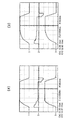
図7に本発明により慣性負荷を変更した場合の速度応答を示す。図7(a)に対して図7(b)は慣性負荷を大きくしている。図7(a)は慣性負荷1542[gcm2]の応答例、図7(b)は慣性負荷2994[gcm2]の応答例である。
波形:上から指令速度30[RPS/2div]、指令トルク1[Nm/2div]、実速度12.82[RPS/div]、時間軸50[msec/div]
慣性負荷が大きくなるにつれて加減速が緩やかになることが分かる。
FIG. 7 shows a speed response when the inertia load is changed according to the present invention. In contrast to FIG. 7A, FIG. 7B increases the inertial load. FIG. 7A shows a response example of the inertial load 1542 [gcm 2 ], and FIG. 7B shows a response example of the inertial load 2994 [gcm 2 ].
Waveform: Command speed 30 [RPS / 2div], command torque 1 [Nm / 2div], actual speed 12.82 [RPS / div], time axis 50 [msec / div]
It can be seen that the acceleration / deceleration becomes gentle as the inertial load increases.
図8に摩擦負荷を変更した場合の速度応答を示す。図8(a)に対して図8(b)は、摩擦負荷を大きく設定している。図8(a)は摩擦負荷0.08[Nm]の応答例、図8(b)は摩擦負荷0.2[Nm]の応答例である。
波形:上から指令速度30[RPS/2div]、指令トルク1[Nm/2div]、実速度12.82[RPS/div]、時間軸50[msec/div]
摩擦負荷があるときは摩擦が減速時のブレーキトルクになり減速時間が短縮されることがわかる。
FIG. 8 shows the speed response when the friction load is changed. In FIG. 8B, the friction load is set larger than that in FIG. FIG. 8A shows a response example of a friction load of 0.08 [Nm], and FIG. 8B shows a response example of a friction load of 0.2 [Nm].
Waveform: Command speed 30 [RPS / 2div], command torque 1 [Nm / 2div], actual speed 12.82 [RPS / div], time axis 50 [msec / div]
It can be seen that when there is a friction load, the friction becomes the braking torque during deceleration and the deceleration time is shortened.
これらのプロファイルが負荷情報の指定だけで運転ごとに自動生成できることが本発明の特徴である。 It is a feature of the present invention that these profiles can be automatically generated for each operation only by specifying load information.
上記実施の形態によれば、システムはモータトルク情報を内部に持ち、指定された負荷情報を元に速度別に加速トルクから加速度を計算し、加速中、減速中に加速度を切り替えながら加減速する。その結果、運転速度プロファイルは移動量と負荷情報の指定によってシステムが決定する。
このように、本発明は、負荷情報と移動量入力だけで位置決め運転ができるようになり、効率の高い最短位置決めが自動生成できる。
トルクマージンを一定に保ち最適効率で運転されるため脱調の不安が低減する。
機器の応答、負担に応じてトルクマージンの指定により運転全体のアグレッシブ度を 容易に変更できる。
フィードバックシステムでないため(開ループ)応答がばらつかない、繰り返し性がよい。
According to the above embodiment, the system has motor torque information inside, calculates acceleration from acceleration torque for each speed based on designated load information, and accelerates / decelerates while switching acceleration during acceleration and deceleration. As a result, the driving speed profile is determined by the system by specifying the movement amount and load information.
As described above, according to the present invention, the positioning operation can be performed only by inputting the load information and the movement amount, and the shortest positioning with high efficiency can be automatically generated.
Since the torque margin is kept constant and the motor is operated at the optimum efficiency, the fear of step-out is reduced.
The aggressiveness of the entire operation can be easily changed by specifying the torque margin according to the response and load of the equipment.
Since it is not a feedback system (open loop), the response does not vary and repeatability is good.
なお、本発明は上記実施の形態のみに限定されるものではなく、本発明の要旨を変更しない範囲内で適宜変更して実施し得ることは言うまでもない。 Needless to say, the present invention is not limited to the above-described embodiment, and may be appropriately modified and implemented without departing from the scope of the present invention.
1 ステッピングモータ
2 モータ駆動回路
3 運転速度プロファイル生成装置
4 リアルタイム指令位置生成装置
DESCRIPTION OF
Claims (2)
運転速度プロファイル生成機能のシステムは
代表的な速度〔V〕、設定電流〔I〕、入力電圧〔Vin〕におけるモータトルク情報を予め記憶装置に所有し、
位置決め運転の実行指令を検出すると、運転開始前に速度プロファイルに関する各値を計算し、
指定された設定電流に対する定格トルクTQ[n]を速度-トルク特性から速度区間V[n]について計算するステップと、
計算された定格トルクTQ[n]と負荷情報から加速時間TA[n]、減速時間TD[n]を計算するステップと、
区間nにおける加速時と減速時の移動量を求め、これを加算して累積移動量を算出するステップと、
上記3ステップを1速度区間とし、それを終える毎に累積移動量と指令移動量を比較するステップと、
累積移動量が指令移動量を超えない場合は区間nをインクリメントして次の速度区間について同じ3ステップを繰り返すステップと、
累積移動量が指令移動量を上回った場合は速度区間を1つ戻し、その速度から三角駆動で残りの移動量を満たすようなピーク速度、加速時間、減速時間を再計算するステップと、
によりプロファイル形状を完成し、
生成した配列を用いて定期処理で指令速度、指令位置をリアルタイムに計算し、モータ駆動回路へ指令位置情報をリアルタイムに伝達して、
加速中、減速中に加速度を切り替えながら加減速することを特徴とするステッピングモータの駆動方法。 In the stepping motor driving method for generating a driving speed profile and controlling the motor driving circuit based on the driving speed profile to drive the stepping motor, load information in addition to the movement amount is input to the driving speed profile generation function. Create a driving speed profile and control the motor drive circuit from position information that changes in real time based on this driving speed profile to drive the stepping motor,
The system of the operation speed profile generation function has motor torque information in a typical speed [V], set current [I], and input voltage [Vin] in a storage device in advance.
When an execution command for positioning operation is detected, each value related to the speed profile is calculated before the operation starts.
Calculating a rated torque TQ [n] for a specified set current from a speed-torque characteristic for a speed section V [n];
Calculating acceleration time TA [n] and deceleration time TD [n] from the calculated rated torque TQ [n] and load information;
Calculating a movement amount at the time of acceleration and deceleration in the section n, and adding this to calculate a cumulative movement amount;
The above three steps are set as one speed section, and the accumulated movement amount and the command movement amount are compared each time it is finished,
If the cumulative movement amount does not exceed the command movement amount, incrementing the section n and repeating the same three steps for the next speed section;
When the accumulated movement amount exceeds the command movement amount, the step returns one speed section, and recalculates the peak speed, acceleration time, and deceleration time that satisfy the remaining movement amount by triangular drive from that speed;
To complete the profile shape,
Using the generated array, the command speed and command position are calculated in real time by regular processing, and command position information is transmitted to the motor drive circuit in real time.
A driving method for a stepping motor, wherein acceleration and deceleration are performed while switching acceleration during acceleration and deceleration.
Priority Applications (1)
| Application Number | Priority Date | Filing Date | Title |
|---|---|---|---|
| JP2006001967A JP4987302B2 (en) | 2006-01-10 | 2006-01-10 | Driving method of stepping motor |
Applications Claiming Priority (1)
| Application Number | Priority Date | Filing Date | Title |
|---|---|---|---|
| JP2006001967A JP4987302B2 (en) | 2006-01-10 | 2006-01-10 | Driving method of stepping motor |
Publications (2)
| Publication Number | Publication Date |
|---|---|
| JP2007185052A JP2007185052A (en) | 2007-07-19 |
| JP4987302B2 true JP4987302B2 (en) | 2012-07-25 |
Family
ID=38340674
Family Applications (1)
| Application Number | Title | Priority Date | Filing Date |
|---|---|---|---|
| JP2006001967A Active JP4987302B2 (en) | 2006-01-10 | 2006-01-10 | Driving method of stepping motor |
Country Status (1)
| Country | Link |
|---|---|
| JP (1) | JP4987302B2 (en) |
Families Citing this family (1)
| Publication number | Priority date | Publication date | Assignee | Title |
|---|---|---|---|---|
| CN113783481B (en) * | 2021-08-10 | 2024-02-02 | 深圳市国赛生物技术有限公司 | Motor control method, device, system and storage medium |
Family Cites Families (2)
| Publication number | Priority date | Publication date | Assignee | Title |
|---|---|---|---|---|
| JP2000175494A (en) * | 1998-12-09 | 2000-06-23 | Fuji Photo Film Co Ltd | Method for controlling stepping motor |
| JP2002078387A (en) * | 2000-08-31 | 2002-03-15 | Y E Data Inc | Method of driving stepping motor |
-
2006
- 2006-01-10 JP JP2006001967A patent/JP4987302B2/en active Active
Also Published As
| Publication number | Publication date |
|---|---|
| JP2007185052A (en) | 2007-07-19 |
Similar Documents
| Publication | Publication Date | Title |
|---|---|---|
| US9768716B2 (en) | Motor control apparatus provided with magnetic flux control unit, and machine learning apparatus and method thereof | |
| JP2007209179A (en) | Vibration wave motor drive control unit | |
| JP5623757B2 (en) | Motor control method and apparatus | |
| US9535426B2 (en) | Positioning control device | |
| JP2011176907A5 (en) | ||
| JP2015035926A (en) | Device and method for controlling stepping motor | |
| JPWO2004008624A1 (en) | Servo controller gain adjustment method | |
| JP5689491B2 (en) | Servo motor control device | |
| JP4987302B2 (en) | Driving method of stepping motor | |
| JP4601659B2 (en) | Command generation apparatus and command generation method | |
| JP4542668B2 (en) | Pulse oscillation IC and motor positioning control method and apparatus using the IC | |
| EP1533890B1 (en) | Motor control device | |
| JP6334017B1 (en) | Induction motor control device | |
| JP2006217746A (en) | Motor controller | |
| JP4250051B2 (en) | Control device for position control motor | |
| JP5904865B2 (en) | Electric motor control device | |
| US20130076284A1 (en) | Motor drive device, and motor drive method | |
| JP2008225652A (en) | Numerical control device | |
| JP6184726B2 (en) | Driving method and driving apparatus for stepping motor | |
| JP3875674B2 (en) | Control method of proportional integral controller | |
| JP4972318B2 (en) | Stepping motor driving method and driving apparatus thereof | |
| WO2022202806A1 (en) | Control device for synchronous motor | |
| JPH08275588A (en) | Drive controller for stepping motor | |
| JP6799022B2 (en) | Tap processing control device | |
| JP5667906B2 (en) | Power converter |
Legal Events
| Date | Code | Title | Description |
|---|---|---|---|
| A621 | Written request for application examination |
Free format text: JAPANESE INTERMEDIATE CODE: A621 Effective date: 20081210 |
|
| A977 | Report on retrieval |
Free format text: JAPANESE INTERMEDIATE CODE: A971007 Effective date: 20110406 |
|
| A131 | Notification of reasons for refusal |
Free format text: JAPANESE INTERMEDIATE CODE: A131 Effective date: 20110408 |
|
| A521 | Request for written amendment filed |
Free format text: JAPANESE INTERMEDIATE CODE: A523 Effective date: 20110606 |
|
| A131 | Notification of reasons for refusal |
Free format text: JAPANESE INTERMEDIATE CODE: A131 Effective date: 20120127 |
|
| A521 | Request for written amendment filed |
Free format text: JAPANESE INTERMEDIATE CODE: A523 Effective date: 20120306 |
|
| TRDD | Decision of grant or rejection written | ||
| A01 | Written decision to grant a patent or to grant a registration (utility model) |
Free format text: JAPANESE INTERMEDIATE CODE: A01 Effective date: 20120330 |
|
| A01 | Written decision to grant a patent or to grant a registration (utility model) |
Free format text: JAPANESE INTERMEDIATE CODE: A01 |
|
| A61 | First payment of annual fees (during grant procedure) |
Free format text: JAPANESE INTERMEDIATE CODE: A61 Effective date: 20120425 |
|
| R150 | Certificate of patent or registration of utility model |
Ref document number: 4987302 Country of ref document: JP Free format text: JAPANESE INTERMEDIATE CODE: R150 Free format text: JAPANESE INTERMEDIATE CODE: R150 |
|
| FPAY | Renewal fee payment (event date is renewal date of database) |
Free format text: PAYMENT UNTIL: 20150511 Year of fee payment: 3 |
|
| R250 | Receipt of annual fees |
Free format text: JAPANESE INTERMEDIATE CODE: R250 |
|
| R250 | Receipt of annual fees |
Free format text: JAPANESE INTERMEDIATE CODE: R250 |
|
| R250 | Receipt of annual fees |
Free format text: JAPANESE INTERMEDIATE CODE: R250 |
|
| R250 | Receipt of annual fees |
Free format text: JAPANESE INTERMEDIATE CODE: R250 |
|
| R250 | Receipt of annual fees |
Free format text: JAPANESE INTERMEDIATE CODE: R250 |
|
| R250 | Receipt of annual fees |
Free format text: JAPANESE INTERMEDIATE CODE: R250 |
|
| R250 | Receipt of annual fees |
Free format text: JAPANESE INTERMEDIATE CODE: R250 |
|
| R250 | Receipt of annual fees |
Free format text: JAPANESE INTERMEDIATE CODE: R250 |
|
| R250 | Receipt of annual fees |
Free format text: JAPANESE INTERMEDIATE CODE: R250 |
|
| R250 | Receipt of annual fees |
Free format text: JAPANESE INTERMEDIATE CODE: R250 |