JP4986934B2 - Graphic region extraction apparatus, graphic region extraction method, program, and recording medium - Google Patents
Graphic region extraction apparatus, graphic region extraction method, program, and recording medium Download PDFInfo
- Publication number
- JP4986934B2 JP4986934B2 JP2008141611A JP2008141611A JP4986934B2 JP 4986934 B2 JP4986934 B2 JP 4986934B2 JP 2008141611 A JP2008141611 A JP 2008141611A JP 2008141611 A JP2008141611 A JP 2008141611A JP 4986934 B2 JP4986934 B2 JP 4986934B2
- Authority
- JP
- Japan
- Prior art keywords
- graphic
- region
- extraction
- image
- area
- Prior art date
- Legal status (The legal status is an assumption and is not a legal conclusion. Google has not performed a legal analysis and makes no representation as to the accuracy of the status listed.)
- Active
Links
Images


Landscapes
- Image Analysis (AREA)
Description
本発明は、画像中の所定の図形領域を抽出するための技術に関するものであり、特に、文字等の線図形からなる領域を画像から抽出するのに適した図形領域抽出技術に関するものである。 The present invention relates to a technique for extracting a predetermined graphic area in an image, and more particularly, to a graphic area extraction technique suitable for extracting an area composed of line figures such as characters from an image.
画像から線図形等の図形の領域を抽出する技術に関しては従来から種々の技術が提案されている。そのような技術の1つとして、画像から抽出対象とする図形(線画等)らしさを表す特徴量を抽出し、その特徴量の密集度を局所領域ごとに算出し、密集度の高い領域の分布に基づいて図形領域を抽出する方法がある(例えば、特許文献1)。
しかしながら、上記従来の技術では、密集度算出の際に図形の連結性を考慮していないため、図形の構成要素の形状や間隔等の影響によって抽出される特徴量が少なくなる部分領域が生じた場合に、1つの図形領域となるべきものが複数の領域に分割して抽出されてしまう場合があった。 However, since the conventional technology does not consider the connectivity of graphics when calculating the density, there is a partial region in which the feature quantity extracted is reduced due to the shape and spacing of the components of the graphic. In some cases, what is supposed to be one graphic area is divided into a plurality of areas and extracted.
また、従来の技術では、画像を図形領域の形状に関わらずに局所領域(ブロック)に分割して処理しており、そのブロック単位で図形の含有を判定しているため、図形領域の特定精度が低いという問題があった。 In addition, in the conventional technology, the image is divided into local areas (blocks) regardless of the shape of the graphic area, and processing is performed. There was a problem of low.
本発明は上記の点に鑑みてなされたものであり、画像中の図形らしさを表す特徴量の空間的密集度とその分布に基づいて図形領域を抽出する技術において、図形の構成要素の形状や間隔等の影響によって1つの図形領域内において抽出される特徴量が少なくなる部分領域が生じたとしても、安定して図形領域を抽出することができ、かつ図形領域の特定精度が高くなる技術を提供することを目的とする。 The present invention has been made in view of the above points, and in the technology for extracting a graphic region based on the spatial density and distribution of feature amounts representing the graphic likeness in an image, A technique that can stably extract a graphic region and increase the accuracy of specifying a graphic region even if a partial region in which a feature amount extracted in one graphic region is reduced due to the influence of an interval or the like is generated. The purpose is to provide.
上記の課題を解決するために、本発明は、所定の種類の図形を含む矩形の領域である図形領域を画像から抽出するための図形領域抽出装置であって、データ格納手段から画像を取得する画像取得手段と、前記画像から、前記図形の図形らしさを示す特徴量としてエッジを抽出し、当該特徴量を画素値とする特徴量抽出結果画像としてエッジ画像を取得する特徴量抽出手段と、前記図形領域の概形状として前記図形領域の長辺方向を示す情報であって、前記矩形が縦長であるか、横長であるかを示す情報である図形領域形状情報を取得する図形領域形状取得手段と、前記図形領域形状情報により示される長辺方向と同じ方向を長辺方向とする長方形である局所領域を設け、前記特徴量抽出結果画像上の各画素に対して、当該画素が中心となる位置に配置した前記局所領域内に含まれる特徴量の和を当該画素の密集度として算出し、前記画像における前記密集度が高い領域を前記図形領域として抽出する図形領域抽出手段とを備えたことを特徴とする図形領域抽出装置として構成される。 In order to solve the above-described problems, the present invention is a graphic region extraction apparatus for extracting a graphic region, which is a rectangular region including a predetermined type of graphic, from an image, and acquires an image from a data storage unit. an image acquisition means, from the image, an edge is extracted as a feature amount indicating a shape likeness of the figure, a feature amount extracting means for obtaining an edge image of the feature quantity as a feature extraction result image to the pixel value, the what information der showing a long side of the diagram area as approximate shape of the graphic region, the one rectangle is vertically elongated, graphic region shape obtaining means for obtaining graphic area shape information indicating whether the horizontal And a local region that is a rectangle whose long side direction is the same as the long side direction indicated by the graphic region shape information, and for each pixel on the feature amount extraction result image, the pixel is centered. Place And a graphic area extracting means for calculating the sum of the feature amounts included in the local area arranged as a pixel density as the pixel area and extracting the area with the high density in the image as the graphic area. It is configured as a featured graphic region extraction device.
前記図形領域抽出装置において、前記図形領域抽出手段は、前記データ格納手段から、所定の密集度算出領域において段階的に複数の重みを設定するための重み係数分布情報を取得する手段と、前記特徴量抽出結果画像に対して前記密集度算出領域を設け、前記図形領域における領域終端部分及びその近傍において前記密集度算出領域の位置をずらしながら、当該密集度算出領域内に含まれる特徴量に前記重み係数分布情報に基づく重みを付けてその和を算出し、当該和の値が予め定めた閾値以上になる前記密集度算出領域の位置に基づき前記図形領域における領域終端の位置を修正する領域終端精密抽出処理手段とを備えることとしてもよい。 In the graphic area extracting apparatus, the graphic area extracting means acquires, from the data storage means, weight coefficient distribution information for setting a plurality of weights stepwise in a predetermined density calculation area; The density calculation result area is provided for the quantity extraction result image, and the feature amount included in the density calculation area is shifted while shifting the position of the density calculation area at and near the end of the area in the graphic area. A region end that calculates the sum by applying a weight based on the weight coefficient distribution information, and corrects the position of the region end in the graphic region based on the position of the density calculation region where the value of the sum is equal to or greater than a predetermined threshold It is good also as providing a precise extraction process means .
また、本発明は、上記図形領域抽出装置の処理動作に対応した方法、プログラム、及び当該プログラムを記録したコンピュータ読み取り可能な記録媒体として構成してもよい。 Further, the present invention may be configured as a method, a program corresponding to the processing operation of the graphic region extraction apparatus, and a computer-readable recording medium on which the program is recorded.
本発明によれば、画像中の図形らしさを表す特徴量の空間的密集度とその分布に基づいて図形領域を抽出する技術において、図形の構成要素の形状や間隔等の影響によって1つの図形領域内において抽出される特徴量が少なくなる部分領域が生じたとしても、安定して図形領域を抽出することができ、かつ図形領域の特定精度が高くなる技術を提供することができる。 According to the present invention, in a technique for extracting a graphic area based on the spatial density of feature quantities representing the graphic likeness in an image and its distribution, one graphic area is influenced by the shape, spacing, etc. of the constituent elements of the graphic. Even if a partial region in which the feature amount extracted is reduced, a graphic region can be extracted stably, and a technique for increasing the accuracy of specifying the graphic region can be provided.
以下、本発明の実施の形態について説明する。 Embodiments of the present invention will be described below.
(第1の実施の形態)
<装置構成>
図1に、本実施の形態における図形領域抽出装置1の機能構成図を示す。図1に示すように、本実施の形態における図形領域抽出装置1は、データ格納部11、画像取得部12、特徴量抽出部13、図形領域形状取得部14、密集度算出用情報取得部15、図形領域抽出部16、及び入出力部17を有する。
(First embodiment)
<Device configuration>
FIG. 1 shows a functional configuration diagram of a graphic
データ格納部11は、本実施の形態における処理で用いられるデータを格納するとともに、各機能部からデータ要求を受信し、当該データ要求に係るデータを要求元の機能部に返す機能部である。図2に、本実施の形態においてデータ格納部11に格納されるデータの例を示す。図2に示すように、データ格納部11には、画像IDと対応付けて、画像データ(単に"画像"と呼ぶことにする)と図形領域形状情報を保持するテーブル(図2(a))と、図形領域形状情報に対応付けて密集度算出領域形状情報と重み係数分布情報を保持するテーブル(図2(b))とが格納されている。各情報の内容については、装置動作の説明の際に説明する。 The data storage unit 11 is a functional unit that stores data used in the processing according to the present embodiment, receives a data request from each functional unit, and returns data related to the data request to the functional unit that is the request source. FIG. 2 shows an example of data stored in the data storage unit 11 in the present embodiment. As shown in FIG. 2, the data storage unit 11 stores image data (simply called “image”) and graphic area shape information in association with an image ID (FIG. 2A). And a table (FIG. 2B) that holds the density calculation area shape information and the weight coefficient distribution information in association with the figure area shape information. The contents of each information will be described when the apparatus operation is described.
データ格納部11は、図形領域抽出装置1として使用されるコンピュータにおける磁気ディスク装置、光ディスク装置、メモリ等で構成される。また、データ格納部11を図形領域抽出装置1内部に備えることに代えて、図形領域抽出装置1とは別の装置としてネットワーク上に配置することとしてもよい。例えば、データ格納部11として、図形領域抽出装置1とネットワークを介して接続されるサーバ装置を用いることができる。
The data storage unit 11 includes a magnetic disk device, an optical disk device, a memory, and the like in a computer used as the graphic
なお、本実施の形態において、"画像"は映像(動画像)でもよいし、静止画像でもよい。また、画像の内容も特に限定されるものでなく、その内容としては例えば、自然画像、人工画像、顔画像、文書を画像化したデータ等がある。また、データ格納部11に格納される画像には、事前に前処理等が施されていてもよい。 In the present embodiment, the “image” may be a video (moving image) or a still image. Also, the content of the image is not particularly limited. Examples of the content include a natural image, an artificial image, a face image, and data obtained by imaging a document. Further, the image stored in the data storage unit 11 may be subjected to preprocessing or the like in advance.
画像取得部12は、データ格納部11に対して画像要求信号を送り、データ格納部11から画像を取得し、取得した画像を特徴量抽出部13に出力する機能部である。特徴量抽出部13は、画像取得部12から受け取った画像に対して特徴量抽出処理を実施し、その結果と画像IDとを図形領域形状取得部14に渡す機能部である。図形領域形状取得部14は、データ格納部11から図形領域形状情報を取得する機能部である。
The
また、密集度算出用情報取得部15は、データ格納部11から密集度算出に必要な情報を取得し、その情報等を図形領域抽出部16に渡す機能部である。図形領域抽出部16は、密集度算出用情報取得部15から受け取った情報等を用いて、特徴量抽出処理結果から図形領域を抽出する機能部である。また、図形領域抽出部16は、更に、密集度算出用情報取得部15から受け取った情報を用いて、図形領域における領域終端の精密抽出を行う機能も有している。入出力部17は、データの入出力をするための機能部である。
The density calculation
なお、図形領域抽出装置1は、CPUと、メモリやハードディスク等の記憶装置とを含む一般的なコンピュータに、本実施の形態で説明する処理に対応するプログラムを実行させることにより実現されるものであり、上述した各機能部は、コンピュータに当該プログラムが実行されて実現される機能部である。従って、例えば、各機能部間での情報のやりとりは、実際にはメモリ等の記憶装置を介して行われるものである。上記プログラムは、メモリ等の記録媒体に格納し、そこからコンピュータにインストールすることもできるし、ネットワーク上のサーバからダウンロードするようにしてもよい。
The graphic
<図形領域抽出装置1の動作>
次に、本実施の形態における図形領域抽出装置1の動作について、図3に示すフローチャートに沿って説明する。
<Operation of Graphic Region Extraction
Next, the operation of the graphic
まず、画像取得部12は、取得するべき画像を示す画像IDを、入力情報として入出力部から受信する。そして、画像取得部は、データ格納部から当該画像IDに対応する画像を取得し、その画像を特徴量抽出部13に渡す(ステップ1)。
First, the
そして、特徴量抽出部13は、画像取得部12から渡された画像に対して予め定めた特徴量抽出処理を実施し、特徴量抽出処理結果と画像IDとを図形領域形状取得部14に渡す(ステップ2)。
Then, the feature
特徴量抽出部13が実施する特徴量抽出処理としては、例えば、エッジ抽出処理(ソーベル演算子を用いたエッジ抽出処理等)がある。特徴量抽出処理としてエッジ抽出処理を行う場合、特徴量抽出部13は、処理対象の画像全体の各画素のエッジ値を算出し、特徴量抽出結果として、エッジ抽出を行った後のエッジ画像を出力する。
Examples of the feature amount extraction processing performed by the feature
続いて、図形領域形状取得部14は、特徴量抽出部13から受け取った画像IDを用い、データ格納部11から当該画像IDに対応する図形領域形状情報を取得し、図形領域形状情報、及び特徴量抽出結果を密集度算出用情報取得部15に渡す(ステップ3)。
Subsequently, the graphic region
図形領域形状情報とは、抽出しようとしている図形領域の形状を示す情報である。本実施の形態では、図形領域として矩形(長方形)を用いることとしており、図形領域形状情報は、抽出対象の領域に含まれる図形(例えば文字列)を包含(外接)する矩形が縦長であるか、横長であるかを示す情報である。図形領域形状情報は、例えば、「縦」もしくは「横」を示す1ビットの情報である。 The graphic area shape information is information indicating the shape of the graphic area to be extracted. In the present embodiment, a rectangle (rectangle) is used as the graphic area, and the graphic area shape information indicates whether the rectangle that includes (circumscribes) the graphic (for example, a character string) included in the extraction target area is vertically long. , Information indicating whether the image is horizontally long. The graphic area shape information is, for example, 1-bit information indicating “vertical” or “horizontal”.
続いて、密集度算出用情報取得部15は、図形領域形状取得部14から受け取った図形領域形状情報を用いて、データ格納部11から当該図形領域形状情報に対応する密集度算出領域形状情報を取得し、当該密集度算出領域形状情報と特徴量抽出結果とを図形領域抽出部16に渡す(ステップ4)。密集度算出領域形状情報は、後述する密集度算出に用いるサブブロック(局所領域)の形状を示す情報であり、例えば、サブブロックの縦方向の画素数と横方向の画素数を有する情報である。そして、本実施の形態において、当該サブブロックは、図形領域形状情報が「横」を示す情報である場合は、横に長い長方形であり、図形領域形状情報が「縦」を示す情報である場合は、縦に長い長方形であることとしている。サブブロックが横に長い長方形である場合、その長方形は例えば縦1×横10の比率の長方形であり、例えば、縦10画素×横100画素の長方形である。このようなサブブロックを採用することにより、図形(文字列等)が連続する方向の特徴量の連続性を優先的に考慮した密集度算出が可能となり、図形領域の抽出精度を向上させることができる。
Subsequently, the density calculation
続いて図形領域抽出部16は、図形抽出処理を行う(ステップ5)。ここでは、図形領域抽出部16は、特徴量抽出結果(各画素の値が特徴量の値である画像)の各画素に対して、密集度算出領域形状情報に対応するサブブロックを適用し、サブブロック内に含まれる各画素の特徴量の値(特徴量抽出処理にてエッジ抽出処理を用いた場合には、特徴量はエッジ値)の和を算出する。この和を、各画素に対する密集度と呼ぶ。つまり、ある画素に注目した場合、その注目画素を中心とするサブブロックに含まれる各画素の特徴量の値の和が、その注目画素における密集度になる。
Subsequently, the graphic
この密集度を特徴量抽出結果の全画素について求める。なお、全画素について密集度を求める代わりに、予め定めた間隔の画素毎に求めることとしてもよい。また、図形(文字列等)が存在しないことがわかっている部分を除く予め定めた位置の画素についてだけ密集度を求めることとしてもよい。 This density is obtained for all pixels of the feature amount extraction result. In addition, it is good also as calculating | requiring for every pixel of the predetermined space | interval instead of calculating | requiring a density about all the pixels. Alternatively, the density may be obtained only for pixels at a predetermined position excluding a portion where a figure (a character string or the like) is known not to exist.
そして、図形領域抽出部16は更に、密集度算出結果に対してクラスタリング処理を実施し、密集度がある閾値より高い画素が一定以上の面積に集合している領域を検出する。そして、クラスタ(密集度がある閾値より高い画素のまとまり)を形成する画素数が予め定めた閾値以上の場合に、そのクラスタを図形の領域であると判断する。
Then, the graphic
続いて、図形領域抽出部16は、図形の領域であると判断された領域に対してその外接矩形を求める等の整形処理を実施し、整形処理後の形を図形領域抽出結果とする。図形領域抽出結果には、整形後の形の輪郭を示す情報、例えば、長方形(矩形)であれば4つの頂点の座標値を含む。
Subsequently, the graphic
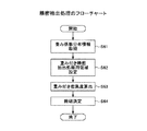
この図形領域抽出結果を出力することとしてもよいが、本実施の形態では、図形領域をより精密に求めるために、多値傾斜重みによる領域終端の精密抽出処理(以下、精密抽出処理と呼ぶ)を行うこととしている(ステップ6)。この精密抽出処理を図4のフローチャートに沿って説明する。 Although this graphic region extraction result may be output, in the present embodiment, in order to obtain the graphic region more precisely, the region end precise extraction processing by multi-value gradient weight (hereinafter referred to as precise extraction processing). (Step 6). This precise extraction process will be described with reference to the flowchart of FIG.
また、以下では、図形領域形状情報が「横」を示す情報である場合を例にとって説明を行う。更に、図3のステップ5で求められた図形領域の左上の頂点の座標値が(Xl、Yu)、右下の頂点の座標値が(Xr、Yd)であるものとする。なお、この時点で、図形領域抽出結果、特徴量抽出結果、図形領域形状情報等はメモリ等の記憶装置に保持されており、以下の処理では当該記憶装置から必要なデータが適宜読み出されて処理が行われる。
In the following description, the case where the graphic area shape information is information indicating “horizontal” will be described as an example. Further, it is assumed that the coordinate value of the upper left vertex of the graphic area obtained in
精密抽出処理において、まず、密集度算出用情報取得部15は、図形領域形状情報に対応する重み係数分布情報をデータ記録部11から取得する(ステップ61)。
In the precise extraction process, first, the density calculation
本実施の形態では、図形領域形状情報が「横」を示す情報である場合、図3のステップ5で抽出された図形領域(横長の長方形)の左端部分と右端部分に対して、領域終端の精密抽出処理を行い、図形領域形状情報が「縦」を示す情報である場合は、上端部分と下端部分に対して、領域終端の精密抽出処理を行うこととしている。従って、データ格納部11には、図2(b)に示すように、図形領域形状情報「横」に対して、左端部分に対応する重み係数分布情報と右端部分に対応する重み係数分布情報が格納され、図形領域形状情報「縦」に対して、上端部分に対応する重み係数分布情報と下端部分に対応する重み係数分布情報が格納されている。
In this embodiment, when the graphic region shape information is information indicating “horizontal”, the region end of the graphic region (horizontal rectangle) extracted at
本例では、図形領域形状情報は「横」であるから、ステップ61において、密集度算出用情報取得部15は、左端部分に対応する重み係数分布情報と右端部分に対応する重み係数分布情報をデータ記録部11から取得する。
In this example, since the shape area shape information is “horizontal”, in step 61, the density calculation
図形領域形状情報が「横」の場合、後述する精密抽出処理用領域として、図形領域の縦方向と同じ画素数を縦方向の画素数として持ち、横方向の画素数として重み係数分布情報により指定される画素数を持つ領域を用いる。つまり、図形領域形状情報が「横」の場合における重み係数分布情報は、この精密抽出処理用領域の横方向の長さ(画素数、wとする)と、横方向における重みの分布の情報を含む。例えば、重み係数分布情報は、精密抽出処理用領域の横方向の長さ(画素数)が5画素であり、左から数えて最初の画素位置(画素1)の重み係数が5、2番目の重み係数が4、3番目の重み係数が3、4番目の重み係数が2、5番目の重み係数が1、等の情報を含む。 When the shape area shape information is “horizontal”, the same number of pixels as the vertical direction of the graphic area is used as the vertical direction pixel count, and the number of horizontal pixels is specified by the weighting factor distribution information. A region having the number of pixels to be used is used. In other words, when the graphic area shape information is “horizontal”, the weight coefficient distribution information includes the horizontal length (number of pixels, w) of the precise extraction processing area and the weight distribution information in the horizontal direction. Including. For example, in the weighting factor distribution information, the length (number of pixels) in the horizontal direction of the precise extraction processing region is 5 pixels, and the weighting factor of the first pixel position (pixel 1) counted from the left is 5, It includes information such as a weighting factor of 4, a third weighting factor of 3, a fourth weighting factor of 2, a fifth weighting factor of 1, and the like.
以下、この重み係数分布情報の例に基づき、左端部分の領域終端精密抽出処理について説明する。なお、右端部分の領域終端精密抽出処理についても行われるが、左端部分の領域終端精密抽出処理と同様(方向が反対になるだけ)であるので、以下では左端部分の領域終端精密抽出処理のみを説明するものである。
図4のステップ61において密集度算出用情報取得部15が取得した左端部分に対応する重み係数分布情報は図形領域抽出部16に渡される。
Hereinafter, based on the example of the weighting factor distribution information, the region end precise extraction processing of the left end portion will be described. It should be noted that the area end precise extraction process at the right end part is also performed, but is the same as the area end precise extraction process at the left end part (only the direction is reversed). Explain.
The weight coefficient distribution information corresponding to the left end portion acquired by the density calculation
図形領域抽出部16は、当該重み係数分布情報を用いて、図形領域の縦方向と同じ画素数を縦方向の画素数として持ち、重み係数分布情報で指定される画素数と同じ画素数を横方向の画素数として持つ精密抽出処理用領域を設け、重み係数分布情報を用いて、精密抽出処理用領域における重み係数分布を、左側の重みが重くなるように設定する(ステップ62)。なお、右端の精密抽出を行う場合には精密抽出処理用領域における重み係数分布を、右側の重みが重くなるように設定する。つまり、図形領域中心側に比べて図形領域終端側の重みが大きくなるように重み付けをする。
Using the weighting factor distribution information, the graphic
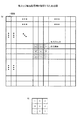
図5は、本例における精密抽出処理を説明するための図であり、図5の上段の602は、精密抽出処理用領域における重み係数分布の例を示している。また、図5の603は、本例における横方向の長さが5の精密抽出処理用領域(精密抽出処理においては、この領域を横方向に移動させながら重み付き密集度を求めることになる)を示している。また、図5に示す例では、特徴量として後述する色エッジペアを用いており、図5では601としてそれが示されている。 FIG. 5 is a diagram for explaining the precise extraction process in this example, and 602 in the upper part of FIG. 5 shows an example of the weight coefficient distribution in the precise extraction process region. Further, reference numeral 603 in FIG. 5 denotes a precision extraction processing area having a horizontal length of 5 in this example (in the precision extraction process, the weighted density is obtained while moving this area in the horizontal direction). Is shown. In the example shown in FIG. 5, a color edge pair described later is used as the feature quantity, which is shown as 601 in FIG. 5.
図形領域の抽出に使用したサブブロックの横の画素数をbとした場合に、図形領域抽出部16は、精密抽出処理用領域の左上端の座標値を、例えば(Xl−b/2、Yu)として、処理対象の特徴量画像における各画素の特徴量値(例えばエッジ値)と、精密抽出処理用領域に対応する画素位置にある重み値との積を精密抽出処理用領域内にある全ての画素に対して算出し、それらの和を算出する(ステップ63)。この和を重み付き密集度と呼ぶ。
When the number of horizontal pixels of the sub-block used for extracting the graphic area is b, the graphic
図形領域抽出部16は、精密抽出処理用領域の左上端の座標値を(Xl−b/2、Yu)から(Xl+b/2、Yu)まで1画素分の幅ずつ移動させながら、重み付き密集度を順次算出する(ステップ63)。なお、上記の例では開始点を(Xl−b/2、Yu)とし、終了点を(Xl+b/2、Yu)としているが、この幅をもっと広くとってよいことはいうまでもない。例えば、(Xl−b、Yu)から(Xl+b、Yu)まで重み付き密集度を順次算出してもよい。
The graphic
そして、図形領域抽出部16は、この重み付き密集度の値が予め設定した閾値を越える(又は閾値以上となる)ときの精密抽出処理用領域の左上端の座標値を(X0、Yu)とし、このときの図形領域の左側の座標値をXlからX0に変更する(ステップ64)。つまり、図形領域の左端を、このときの精密抽出処理用領域の左端の位置とする。図5の下段には、精密抽出処理用領域を横にずらしながら算出した重み付き密集度がグラフの形で表示されており、605の位置で重み付き密集度が閾値を超えたことが示されている。
Then, the graphic
図形領域抽出部16は、図3のステップ5で得られた全ての図形領域に対して、上下もしくは左右の端の精密抽出を実施後の図形領域情報と画像IDとを入出力部17に渡し、入出力部17がこれらの情報を出力する(図3のステップ7)。
The graphic
なお、左右端、上下端の精密抽出を行うことのほか、例えば、左下隅の端を精密に検出する場合には、精密抽出処理用領域において左下の重みを大きくし、左下から離れるに従って重みを小さくした重み分布を用いることにより、左下隅の特徴量の変化を感度良くとらえ、左下隅の端を精度良く検出することも可能である。 In addition to performing precise extraction of the left and right edges and upper and lower edges, for example, when precisely detecting the lower left corner edge, the lower left weight is increased in the precision extraction processing area, and the weight is increased as the distance from the lower left is increased. By using a reduced weight distribution, it is possible to detect the change in the feature quantity at the lower left corner with high sensitivity and to detect the end of the lower left corner with high accuracy.
また、上述した例では、図形領域形状情報が、予めデータ格納部11に格納されている場合の処理例を示しているが、図形領域形状を抽出する処理を用いて図形領域形状情報を取得してもよい。例えば、予めいくつかの方向(例えば、縦方向及び横方向)を定めておき、それぞれの方向に応じた形状の局所領域を用いて図形領域を抽出した後、どの方向に応じた形状の局所領域を用いて抽出した結果が最も良い結果かを判定し、その方向を図形領域形状情報として出力する処理を行って図形領域形状情報を取得してもよい。 Moreover, although the example mentioned above has shown the processing example in the case where the graphic area shape information is stored in the data storage unit 11 in advance, the graphic area shape information is acquired using the process of extracting the graphic area shape. May be. For example, after defining several directions (for example, the vertical direction and the horizontal direction) in advance and extracting a graphic area using a local area having a shape corresponding to each direction, the local area having a shape corresponding to which direction is extracted. It is also possible to determine whether the result extracted using is the best result, and to obtain the graphic area shape information by performing a process of outputting the direction as the graphic area shape information.
(第2の実施の形態)
次に、本発明の第2の実施の形態について説明する。第2の実施の形態は、第1の実施の形態における特徴量抽出部13が、画像の特徴量として色エッジを算出し、更に色エッジペアを算出する場合の例である。なお、本実施の形態は、領域を抽出する対象の線図形が文字列(テロップ等)である場合に特に適する。
(Second Embodiment)
Next, a second embodiment of the present invention will be described. The second embodiment is an example in which the feature
本実施の形態において、色情報は高次元の情報であり、例えば3次元の情報である。3次元の情報で色を表現するモデルとしては、例えばRGB、HSV、HSI、YUV、LUV、LAB、XYZ等があるが、本発明はどのような色表現方法に対しても適用できる。また、本実施の形態における画像データのデータ格納部11への格納方法の例を図6に示す。図6に示すように、この例では、画素(画素の位置)毎に色の成分値が連続的に格納されている。 In the present embodiment, the color information is high-dimensional information, for example, three-dimensional information. For example, RGB, HSV, HSI, YUV, LUV, LAB, XYZ, and the like are models for expressing colors with three-dimensional information, but the present invention can be applied to any color expression method. An example of a method for storing image data in the data storage unit 11 according to the present embodiment is shown in FIG. As shown in FIG. 6, in this example, color component values are continuously stored for each pixel (pixel position).
<特徴量抽出部13の構成>
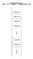
図7に、本実施の形態における特徴量抽出部13の機能構成図を示す。図7に示すように、本実施の形態における特徴量抽出部13は、色エッジ抽出部21、色エッジペア抽出部22、ペア性判定部23を有する。
<Configuration of Feature
FIG. 7 shows a functional configuration diagram of the feature
色エッジ抽出部21は、画像取得部12から受け取った画像に対して色エッジ抽出処理を実施し、その結果を色エッジペア抽出部22に渡す機能部である。色エッジペア抽出部22は、色エッジ抽出処理結果から色エッジペア候補を特定するとともに、ペア性判定部23を用いて、色エッジペア候補から色エッジペアを抽出し、それを含む情報を次の処理部(図形領域形状取得部14)に渡す機能部である。
The color edge extraction unit 21 is a functional unit that performs color edge extraction processing on the image received from the
<特徴量抽出部13の動作>
以下、図8に示すフローチャートに沿って、特徴量抽出部13の動作について説明する。
<Operation of Feature
Hereinafter, the operation of the feature
まず、色エッジ抽出部21は、画像取得部12から処理対象の画像を含む情報を受け取る(ステップ11)。なお、画像取得部12が取得した画像が動画像であった場合には、画像取得部12は、動画像から各フレームを抽出する処理を行い、抽出した各フレームを色エッジ抽出部21に出力し、以下の処理が各フレーム(画像)毎に行われることになる。
First, the color edge extraction unit 21 receives information including an image to be processed from the image acquisition unit 12 (step 11). If the image acquired by the
続いて、色エッジ抽出部21は、画像取得部12から受け取った画像から色エッジを抽出し、色エッジ情報として色エッジペア抽出部22に渡す処理を行う(ステップ12)。
Subsequently, the color edge extraction unit 21 performs a process of extracting a color edge from the image received from the
色エッジの抽出技術としては、色情報が不連続に変化する部分を特徴として抽出することが可能な技術を利用する。このような技術としては、従来から提案されている多くのエッジ抽出技術を利用することができる。例えば、単純差分及びその絶対値を用いるエッジ抽出技術、DoG(微分ガウシアン)演算子を用いるエッジ抽出技術、ソーベルやプレウィット等のエッジ検出演算子を用いるエッジ抽出技術、ラプラシアン演算子を用いるエッジ抽出技術、MAX-MIN演算子を用いるエッジ抽出技術、等のうちのいずれも利用できる。もちろん、ここに挙げていない技術を用いてもよい。 As a color edge extraction technique, a technique that can extract a portion where color information changes discontinuously as a feature is used. As such a technique, many conventionally proposed edge extraction techniques can be used. For example, edge extraction technology using simple difference and its absolute value, edge extraction technology using DoG (differential Gaussian) operator, edge extraction technology using edge detection operators such as Sobel and Prewitt, edge extraction using Laplacian operator Any of a technology, an edge extraction technology using a MAX-MIN operator, and the like can be used. Of course, techniques not listed here may be used.
一例として、ソーベル演算子(3×3)と絶対値を組み合わせた方法を採用する場合において、縦縞エッジの抽出を行う場合の色エッジ抽出部21の処理例を説明する。 As an example, a processing example of the color edge extraction unit 21 in the case where vertical stripe edge extraction is performed in a case where a method combining a Sobel operator (3 × 3) and an absolute value is employed will be described.
ある注目画素(成分値e)の近傍の画素(成分値a〜i)がサブブロックにおいて図9(A)に示すように配置されている場合に、色エッジ抽出部21は、このサブブロックに対して図9(B)に示す3×3ソーベル演算子を適用して絶対値をとることにより、|c−a|+2|f−d|+|i−g|(|・|は・の絶対値)を計算し、これを注目画素の位置の特定の成分のエッジの値とする。なお、ここでの成分とは例えば色情報のR成分等である。 When pixels (component values a to i) in the vicinity of a certain pixel of interest (component value e) are arranged as shown in FIG. 9A in the sub-block, the color edge extraction unit 21 includes the sub-block. On the other hand, by applying the 3 × 3 Sobel operator shown in FIG. 9B and taking the absolute value, | c−a | +2 | f−d | + | i−g | (| · | (Absolute value) is calculated, and this is used as the value of the edge of the specific component at the position of the target pixel. The component here is, for example, an R component of color information.
色エッジ抽出部21は、画像の各画素の各色成分毎にエッジ抽出技術を適用して、画素毎に、色成分毎の色エッジ値を算出する。また、色エッジ抽出部21は、画素毎に、各色成分の色エッジ値の和、もしくは各色成分の色エッジ値からなるベクトルの長さを求め、それを出力すべき色エッジ値とする。なお、各色成分の色エッジ値を1つの色エッジ値にする処理は上記のものに限られるわけではない。 The color edge extraction unit 21 applies an edge extraction technique for each color component of each pixel of the image, and calculates a color edge value for each color component for each pixel. In addition, the color edge extraction unit 21 obtains the sum of the color edge values of each color component or the length of a vector composed of the color edge values of each color component for each pixel, and uses this as the color edge value to be output. Note that the process of setting the color edge value of each color component to one color edge value is not limited to the above.
そして、色エッジ抽出部21は、画素の位置と色エッジ値との組み合わせを色エッジ情報として色エッジペア抽出部22に渡す。
Then, the color edge extraction unit 21 passes the combination of the pixel position and the color edge value to the color edge
色エッジペア抽出部22は、色エッジ抽出部21から受け取った色エッジ情報から色エッジペアの候補となる2つの色エッジの組である色エッジペア候補の集合を生成し、メモリ等の記憶装置に保持しておく(ステップ13)。なお、元の画像の情報(画素位置と色成分の情報)はメモリ等に保持されており、処理の中で必要であれば適宜取得できるものとする。
The color edge
色エッジペア候補を生成する処理において、色エッジペア抽出部22は、例えば、2つの色エッジのエッジ値が閾値以上かつ、それらが予め定められた位置関係にある、かつ、2つの色エッジ間の距離が予め定めた値以下のものを色エッジペア候補として抽出する処理を行う。上記予め定められた位置関係とは、例えば、2つの色エッジが同一Y座標位置上で左右に並んでいる、あるいは、同一X座標位置上で上下に並んでいる等である。
In the process of generating the color edge pair candidate, the color edge
次に、色エッジペア抽出部22は、ペア性判定部23を用いたペア性判定処理に移る。
Next, the color edge
ここではまず、色エッジペア抽出部22は、ステップ13において生成した色エッジペア候補の中にペア性が未判定のものがあるかどうかをチェックする(図8のステップ14)。未判定のものがない場合(ステップ14のNo)、全ての色エッジペア候補に対するペア性判定が済んだことになるので処理を終了する(ステップ18)。
Here, first, the color edge
未判定のものがある場合(ステップ14のYes)、未判定の色エッジペア候補の集合から1つの色エッジペア候補(色エッジ画素の位置を含む情報)を選択し、その色エッジペア候補をペア性判定部23に渡し、ペア性判定部23に当該色エッジペア候補のペア性を判定させる(ステップ15)。
If there is an undetermined one (Yes in step 14), one color edge pair candidate (information including the position of the color edge pixel) is selected from the set of undetermined color edge pair candidates, and the color edge pair candidate is determined as a pair property The data is passed to the
ペア性判定部23は、色エッジペア抽出部22から受け取った色エッジペア候補が色エッジペアのペア性判定条件を満たしているかどうかを判定する。
The pair
ペア性判定条件としては、以下に示すペア性判定条件1〜3を用いる。本実施の形態では、これらのうちの少なくとも1つの条件を満たすものを色エッジペアであると判定する。なお、これらの条件は文字等の線図形の色が局所的には一定であるという性質に着目した条件である。また、ペア性判定条件は下記のものに限定されるわけではない。
As the pairing determination conditions, the following
ペア性判定条件1:色エッジペア候補を構成する2つの色エッジ(色エッジ部分の画素の点)について、相手の色エッジ側にある画素同士の色が類似していること。つまり、この条件は、色エッジペア候補を構成する第1の色エッジと第2の色エッジにおいて、第1の色エッジの周囲にある画素のうち、第2の色エッジに近い側にある画素の色と、第2の色エッジの周囲にある画素のうち、第1の色エッジに近い側にある画素の色とが類似していることという条件である。 Pairability determination condition 1: The colors of pixels on the other color edge side are similar for two color edges (pixel points of the color edge portion) constituting a color edge pair candidate. In other words, this condition is that, among the pixels around the first color edge in the first color edge and the second color edge constituting the color edge pair candidate, the pixel closer to the second color edge is selected. This is a condition that the color and the color of the pixel near the first color edge among the pixels around the second color edge are similar.
色が類似していると判定するための色の類似判定基準としては例えば以下のものがある。 Examples of color similarity determination criteria for determining that colors are similar include the following.
・各画素の色情報の成分値の差の絶対値の和が一定値以下であること。これは例えば、(R成分値の差の絶対値)+(G成分値の差の絶対値)+(G成分値の差の絶対値)が一定値以下であるということである。 -The sum of the absolute values of the difference between the component values of the color information of each pixel is not more than a certain value. This is, for example, that (absolute value of difference in R component value) + (absolute value of difference in G component value) + (absolute value of difference in G component value) is equal to or less than a certain value.
・各画素の色間の距離(例えば、RGB空間でのユークリッド距離)が一定値以下であること。 The distance between colors of each pixel (for example, Euclidean distance in RGB space) is not more than a certain value.
ペア性判定条件1について図10(a)を参照して更に説明する。色エッジペア候補を構成する色エッジの画素101、104が図10(a)に示すように存在する場合において、画素101の相手の色エッジ(画素104)側にある画素は画素102であり、画素104の相手の色エッジ(画素101)側にある画素は画素103である。これらの画素102、103同士を相手の色エッジ側にある画素同士と称している。図10(a)に示す例では、各色エッジにおいて、当該色エッジの画素と、他方の色エッジに近い側の画素とは隣接しているが、必ずしも隣接している必要はない。例えば、画素101と画素102との間、及び画素103と画素104との間は、それぞれ1〜数画素分離れていてもよい。
The
図10(a)に示す例においては、画素102、103の色が類似している場合に、ペア性判定部23は、色エッジペア候補101、104はペア性判定条件を満たしていると判定する。
In the example shown in FIG. 10A, when the colors of the
対象の線図形が文字である場合において、このペア性判定条件1を用いることにより、文字を構成する線の輪郭に色エッジペアが集中して抽出される。ここで、色エッジペア候補選定において、色エッジペア候補間の距離を文字の大きさや文字線の太さに応じて適切に設定することにより、文字の周辺以外に検出される色エッジペアを抑制することもできる。
When the target line figure is a character, by using this
ペア性判定条件2:色エッジペア候補の各色エッジの近傍の画素における色の変化ベクトルがほぼ逆方向であること。つまり、この条件は、色エッジペア候補を構成する第1の色エッジと第2の色エッジにおいて、第1の色エッジ近傍における色の変化ベクトルと、第2の色エッジ近傍における変化ベクトルとがほぼ逆方向となっていることという条件である。 Pairing determination condition 2: The color change vector in the pixel in the vicinity of each color edge of the color edge pair candidate is substantially in the reverse direction. That is, this condition is that the color change vector in the vicinity of the first color edge and the change vector in the vicinity of the second color edge are substantially the same at the first color edge and the second color edge constituting the color edge pair candidate. The condition is that the direction is opposite.
なお、例えば、RGB色空間の中で、R成分、G成分、B成分が全て0の画素から、R成分が255、G成分とB成分が0の画素に向けた色の変化ベクトルは、R成分が255、G成分、B成分ともに0のベクトルである。このベクトルと逆ベクトルとは、R成分が−255、G成分、B成分が0のベクトルである。 For example, in the RGB color space, a color change vector from a pixel in which R component, G component, and B component are all 0 to a pixel in which R component is 255, G component, and B component is 0 is R The component is a vector of 255, and the G component and B component are both zero. The vector and the inverse vector are vectors having an R component of −255, a G component, and a B component of 0.
色エッジの近傍の画素とは、例えば、色エッジペア候補を構成する2つの色エッジペアのうちの一方の色エッジ(開始点色エッジと呼ぶ)から他方の色エッジ(終点色エッジと呼ぶ)に向かうベクトルの方向に並ぶ2つの画素であって、開始点色エッジ側においては、開始点色エッジから上記ベクトルと垂直方向に引いた線上において開始点色エッジの近傍に存在する画素(開始点色エッジを含む)と当該画素の上記ベクトルの方向側に並ぶ画素との2つの画素であり、終点色エッジ側においては、終点色エッジから上記ベクトルと垂直方向に引いた線上において終点色エッジの近傍に存在する画素(終点色エッジを含む)と当該画素の上記ベクトルの方向の逆方向側に並ぶ画素との2つの画素である。そして、色エッジの近傍の画素の色の変化ベクトルとは、例えば、開始点色エッジ側においては、上記近傍の画素のうちの開始点色エッジ側に存在する画素の色から、近傍の画素のうちの終点エッジ側に存在する画素の色への変化ベクトルであり、終点色エッジ側においては、近傍の画素のうちの開始点色エッジ側に存在する画素の色から、近傍の画素のうちの終点エッジ側に存在する画素の色への変化ベクトルである。 The pixel in the vicinity of the color edge is, for example, from one color edge (referred to as a start point color edge) of two color edge pairs constituting a color edge pair candidate to the other color edge (referred to as an end point color edge). Two pixels lined up in the direction of the vector, and on the start point color edge side, pixels existing in the vicinity of the start point color edge on the line drawn from the start point color edge in the direction perpendicular to the vector (start point color edge) And the pixels lined up in the direction of the vector of the pixel. On the end color edge side, on the line drawn from the end point color edge in the direction perpendicular to the vector, it is in the vicinity of the end color edge. There are two pixels: an existing pixel (including an end color edge) and a pixel arranged on the opposite side of the vector direction of the pixel. The color change vector of the pixel in the vicinity of the color edge is, for example, on the start point color edge side, from the color of the pixel existing on the start point color edge side in the vicinity pixel, This is a change vector to the color of the pixel existing on the end edge side, and on the end color edge side, from the color of the pixel existing on the start point color edge side of the neighboring pixels, It is a change vector to the color of a pixel existing on the end edge side.
また、色エッジの近傍の画素の色の変化ベクトルとして、開始点色エッジ側において、開始点色エッジから上記ベクトルと垂直方向に引いた線上において開始点色エッジの近傍に存在する複数の画素(例えば開始点色エッジとその上下にある2つの画素の3画素)の色の平均から、当該複数の画素のそれぞれについて上記ベクトルの方向側に並ぶ複数の画素(例えば上記3画素に隣接して上記ベクトルの方向側に並ぶ3画素)の色の平均への変化ベクトルを用い、終点色エッジ側において、終点色エッジから上記ベクトルと垂直方向に引いた線上において終点色エッジの近傍に存在する複数の画素(例えば終点色エッジとその上下にある2つの画素の3画素)の色の平均から、当該複数の画素のそれぞれについて上記ベクトルの逆方向側に並ぶ複数の画素(例えば上記3画素に隣接して上記ベクトルの逆方向側に並ぶ3画素)の色の平均を引いた変化ベクトルを用いてもよい。
Further, as a color change vector of a pixel in the vicinity of the color edge, on the start point color edge side, a plurality of pixels (in the vicinity of the start point color edge on a line drawn from the start point color edge in the direction perpendicular to the vector) ( For example, from the average of the colors of the start point color edge and the two pixels above and below it, a plurality of pixels lined up in the direction of the vector for each of the plurality of pixels (for example, adjacent to the three pixels described above) (3 pixels arranged in the direction direction of the vector) using a change vector to the average color, and on the end color edge side, a plurality of pixels existing in the vicinity of the end color edge on the line drawn from the end color edge in the direction perpendicular to the vector From the average of the colors of pixels (for example, the end point color edge and the three pixels above and below it), each of the plurality of pixels is aligned in the opposite direction of the vector. A plurality of pixels may be used change vector obtained by subtracting the average color (adjacent to e.g. the 3
図10(a)に示す例では、色エッジペア候補の一方の色エッジ101の近傍で、画像の画素の色が黒から黄に変化しており、色エッジペア候補の他方の色エッジ104の近傍では色が黄から黒に変化しており、ペア性判定条件2を満たすため、ペア性判定部15は、色エッジペア候補101、104は色エッジペアであると判定する。なお、もちろん、画素101から画素102への色の変化ベクトルと、画素103から画素104への色の変化ベクトルとをペア性判定条件2におけるペア性判定に用いてよい。
In the example shown in FIG. 10A, the color of the pixel of the image changes from black to yellow in the vicinity of one
また、上述したように、図10(b)における画素201、101、301の色の平均から画素202、102、302の色の平均への変化ベクトルと、画素203、103、303の色の平均から画素204、104、304の色の平均への変化ベクトルとをペア性判定に用いてもよい。
Further, as described above, the change vector from the average of the colors of the
ペア性判定条件3:色ヘッジペア候補の2つの色エッジ間での色の変化量が小さいこと。
例えば、この条件は、色エッジペア候補の2つの色エッジ間を結ぶ線分上の画素の各色成分の最大値、最小値の差が予め定めた値以下であることである。また、例えば、色エッジペア候補の2つの色エッジ間を結ぶ線分上の画素の色間の距離(RGB空間でのユークリッド距離等)の最大値が予め定めた値以下であることである。
Pairing determination condition 3: The amount of color change between two color edges of a color hedge pair candidate is small.
For example, this condition is that the difference between the maximum value and the minimum value of each color component of a pixel on a line segment connecting two color edges of a color edge pair candidate is not more than a predetermined value. Further, for example, the maximum value of the distance between the colors of the pixels on the line segment connecting the two color edges of the color edge pair candidate (such as the Euclidean distance in the RGB space) is not more than a predetermined value.
上記のペア性判定条件に基づきペア性判定を行ったペア性判定部23は、色エッジペア抽出部22から受け取った色エッジペア候補に対するペア性判定結果を色エッジペア抽出部22に返し、色エッジペア抽出部22は、ペア性判定部23から色エッジペア候補のペア性判定結果を受け取る。ペア性判定結果を満たしていた場合(図8のステップ16のYes)、色エッジペア抽出部22は、その色エッジペアを色エッジペア抽出結果(特徴量)として出力する(ステップ17)。色エッジペア抽出結果には、色エッジペアに含まれる2つの色エッジの位置(画素の位置)、色成分の値、色エッジ値が含まれる。出力された情報は特徴量抽出処理結果として図形領域形状取得部14に渡される。
The
ペア性判定結果を満たしていない場合(ステップ16のNo)、色エッジペア抽出部22は、ステップ14の処理に戻り、未判定の色エッジペア候補があればその色エッジペア候補に対して上述したペア性判定処理を行うことになる。
If the pairedness determination result is not satisfied (No in Step 16), the color edge
なお、上記の例では、色エッジペア抽出部22は、色エッジペア候補一組毎にペア性判定部23を利用したペア性判定処理を行っているが、色エッジペア候補を全てペア性判定部23に渡し、ペア性を満たす全ての色エッジペアの情報をペア性判定部23から受信し、その情報に基づき、全ての色エッジペア抽出結果を生成し、出力することとしてもよい。
In the above example, the color edge
その後、図形領域抽出装置1は、色エッジペアにおけるエッジ値を特徴量として用いることにより、前述した図形領域抽出処理を行う。
Thereafter, the graphic
(実施の形態の効果について)
上述したように、本発明の実施の形態における技術によれば、図形領域の形状に適応した局所領域(サブブロック)を使用することにより、図形領域の形状(図形領域の連結性等)を考慮して図形の有無を評価できるようになるため、図形の構成要素の形状や間隔などの影響によって1つの図形領域内において抽出される特徴量が少なくなる部分領域が生じたとしても、安定して図形領域を抽出できる。特に、図形領域の形状(テロップ文字列領域の形状等)が予め想定できる場合に、想定される形状に応じた局所領域(横に長い長方形等)を用いることにより、領域の抽出性能を向上できる。
(Effects of the embodiment)
As described above, according to the technique in the embodiment of the present invention, the shape of the graphic region (such as connectivity of the graphic region) is considered by using the local region (sub-block) adapted to the shape of the graphic region. Thus, the presence or absence of a figure can be evaluated. Therefore, even if a partial area in which the amount of features extracted in one figure area is reduced due to the influence of the shape and interval of the figure constituent elements is generated stably The graphic area can be extracted. In particular, when the shape of a graphic area (such as the shape of a telop character string area) can be assumed in advance, the extraction performance of the area can be improved by using a local area (such as a horizontally long rectangle) according to the assumed shape. .
また、多値傾斜重みによる領域終端の精密抽出処理を行うことにより、図形領域中の位置による特徴量の重要度の違い等を密集度算出重みの違いによって考慮しながら評価することができ、より正確に図形領域を抽出できる。 In addition, by performing precise extraction processing at the end of the region with multi-valued gradient weights, it is possible to evaluate differences in the importance of feature amounts depending on the position in the graphic region, taking into account differences in the density calculation weight, The graphic area can be extracted accurately.
本発明は、上記の実施の形態に限定されることなく、特許請求の範囲内において、種々変更・応用が可能である。 The present invention is not limited to the above-described embodiments, and various modifications and applications are possible within the scope of the claims.
1 図形領域抽出装置
11 データ格納部
12 画像取得部
13 特徴量抽出部
14 図形領域形状取得部
15 密集度算出用情報取得部
16 図形領域抽出部
17 入出力部
21 色エッジ抽出部
22 色エッジペア抽出部
23 ペア性判定部
DESCRIPTION OF
Claims (6)
データ格納手段から画像を取得する画像取得手段と、
前記画像から、前記図形の図形らしさを示す特徴量としてエッジを抽出し、当該特徴量を画素値とする特徴量抽出結果画像としてエッジ画像を取得する特徴量抽出手段と、
前記図形領域の概形状として前記図形領域の長辺方向を示す情報であって、前記矩形が縦長であるか、横長であるかを示す情報である図形領域形状情報を取得する図形領域形状取得手段と、
前記図形領域形状情報により示される長辺方向と同じ方向を長辺方向とする長方形である局所領域を設け、前記特徴量抽出結果画像上の各画素に対して、当該画素が中心となる位置に配置した前記局所領域内に含まれる特徴量の和を当該画素の密集度として算出し、
前記画像における前記密集度が高い領域を前記図形領域として抽出する図形領域抽出手段と
を備えたことを特徴とする図形領域抽出装置。 A graphic region extraction device for extracting a graphic region, which is a rectangular region including a predetermined type of graphic, from an image,
Image acquisition means for acquiring an image from the data storage means;
Feature amount extraction means for extracting an edge from the image as a feature amount indicating the graphic likeness of the figure, and acquiring an edge image as a feature amount extraction result image having the feature amount as a pixel value;
What information der showing a long side of the diagram area as approximate shape of the graphic region, the one rectangle is vertically elongated, graphic region shape acquiring for acquiring graphic area shape information indicating whether the horizontal Means,
A local region that is a rectangle having a long side direction that is the same as the long side direction indicated by the graphic region shape information is provided, and for each pixel on the feature amount extraction result image, the pixel is positioned at the center. Calculating the sum of the feature quantities included in the arranged local region as the density of the pixel,
A graphic region extracting device comprising: a graphic region extracting means for extracting the region having a high density in the image as the graphic region.
前記データ格納手段から、所定の密集度算出領域において段階的に複数の重みを設定するための重み係数分布情報を取得する手段と、
前記特徴量抽出結果画像に対して前記密集度算出領域を設け、前記図形領域における領域終端部分及びその近傍において前記密集度算出領域の位置をずらしながら、当該密集度算出領域内に含まれる特徴量に前記重み係数分布情報に基づく重みを付けてその和を算出し、当該和の値が予め定めた閾値以上になる前記密集度算出領域の位置に基づき前記図形領域における領域終端の位置を修正する領域終端精密抽出処理手段と
を備えたことを特徴とする請求項1に記載の図形領域抽出装置。 The graphic region extraction means includes
Means for acquiring weight coefficient distribution information for setting a plurality of weights in a stepwise manner in a predetermined density calculation area from the data storage means;
A feature amount included in the density calculation area while providing the density calculation area for the feature amount extraction result image and shifting the position of the density calculation area at and near the end of the area in the graphic area A weight is added based on the weight coefficient distribution information to calculate the sum, and the position of the region end in the graphic region is corrected based on the position of the density calculation region where the value of the sum is equal to or greater than a predetermined threshold. The graphic region extraction apparatus according to claim 1, further comprising: a region end precise extraction processing unit.
データ格納手段から画像を取得する画像取得ステップと、
前記画像から、前記図形の図形らしさを示す特徴量としてエッジを抽出し、当該特徴量を画素値とする特徴量抽出結果画像としてエッジ画像を取得する特徴量抽出ステップと、
前記図形領域の概形状として前記図形領域の長辺方向を示す情報であって、前記矩形が縦長であるか、横長であるかを示す情報である図形領域形状情報を取得する図形領域形状取得ステップと、
前記図形領域形状情報により示される長辺方向と同じ方向を長辺方向とする長方形である局所領域を設け、前記特徴量抽出結果画像上の各画素に対して、当該画素が中心となる位置に配置した前記局所領域内に含まれる特徴量の和を当該画素の密集度として算出し、前記画像における前記密集度が高い領域を前記図形領域として抽出する図形領域抽出ステップと
を備えることを特徴とする図形領域抽出方法。 A graphic region extraction method executed by a graphic region extraction device for extracting a graphic region that is a rectangular region including a predetermined type of graphic from an image,
An image acquisition step of acquiring an image from the data storage means;
A feature amount extraction step of extracting an edge from the image as a feature amount indicating the graphic likeness of the figure, and acquiring an edge image as a feature amount extraction result image having the feature amount as a pixel value;
What information der showing a long side of the diagram area as approximate shape of the graphic region, the one rectangle is vertically elongated, graphic region shape acquiring for acquiring graphic area shape information indicating whether the horizontal Steps,
A local region that is a rectangle having a long side direction that is the same as the long side direction indicated by the graphic region shape information is provided, and for each pixel on the feature amount extraction result image, the pixel is positioned at the center. A graphic region extracting step of calculating a sum of the feature amounts included in the arranged local region as the density of the pixel, and extracting the region having the high density in the image as the graphic region; and Graphic area extraction method.
前記データ格納手段から、所定の密集度算出領域において段階的に複数の重みを設定するための重み係数分布情報を取得するステップと、
前記特徴量抽出結果画像に対して前記密集度算出領域を設け、前記図形領域における領域終端部分及びその近傍において前記密集度算出領域の位置をずらしながら、当該密集度算出領域内に含まれる特徴量に前記重み係数分布情報に基づく重みを付けてその和を算出し、当該和の値が予め定めた閾値以上になる前記密集度算出領域の位置に基づき前記図形領域における領域終端の位置を修正する領域終端精密抽出処理ステップと
を備えたことを特徴とする請求項3に記載の図形領域抽出方法。 The graphic region extraction step includes:
Obtaining weight coefficient distribution information for setting a plurality of weights in a stepwise manner in a predetermined density calculation area from the data storage means;
A feature amount included in the density calculation area while providing the density calculation area for the feature amount extraction result image and shifting the position of the density calculation area at and near the end of the area in the graphic area A weight is added based on the weight coefficient distribution information to calculate the sum, and the position of the region end in the graphic region is corrected based on the position of the density calculation region where the value of the sum is equal to or greater than a predetermined threshold. The graphic region extraction method according to claim 3 , further comprising: a region end precision extraction processing step.
Priority Applications (1)
| Application Number | Priority Date | Filing Date | Title |
|---|---|---|---|
| JP2008141611A JP4986934B2 (en) | 2008-05-29 | 2008-05-29 | Graphic region extraction apparatus, graphic region extraction method, program, and recording medium |
Applications Claiming Priority (1)
| Application Number | Priority Date | Filing Date | Title |
|---|---|---|---|
| JP2008141611A JP4986934B2 (en) | 2008-05-29 | 2008-05-29 | Graphic region extraction apparatus, graphic region extraction method, program, and recording medium |
Publications (2)
| Publication Number | Publication Date |
|---|---|
| JP2009289075A JP2009289075A (en) | 2009-12-10 |
| JP4986934B2 true JP4986934B2 (en) | 2012-07-25 |
Family
ID=41458228
Family Applications (1)
| Application Number | Title | Priority Date | Filing Date |
|---|---|---|---|
| JP2008141611A Active JP4986934B2 (en) | 2008-05-29 | 2008-05-29 | Graphic region extraction apparatus, graphic region extraction method, program, and recording medium |
Country Status (1)
| Country | Link |
|---|---|
| JP (1) | JP4986934B2 (en) |
Families Citing this family (2)
| Publication number | Priority date | Publication date | Assignee | Title |
|---|---|---|---|---|
| JP5463269B2 (en) * | 2010-11-24 | 2014-04-09 | 日本電信電話株式会社 | Feature figure addition method, feature figure detection method, feature figure addition device, feature figure detection device, and program |
| CN112017203A (en) * | 2019-05-31 | 2020-12-01 | 广州市百果园信息技术有限公司 | Image processing method, video processing method, device, equipment and storage medium |
Family Cites Families (2)
| Publication number | Priority date | Publication date | Assignee | Title |
|---|---|---|---|---|
| JP3544324B2 (en) * | 1999-09-08 | 2004-07-21 | 日本電信電話株式会社 | CHARACTER STRING INFORMATION EXTRACTION DEVICE AND METHOD, AND RECORDING MEDIUM CONTAINING THE METHOD |
| JP4870721B2 (en) * | 2008-05-29 | 2012-02-08 | 日本電信電話株式会社 | Image feature extraction apparatus, image feature extraction method, program, and recording medium |
-
2008
- 2008-05-29 JP JP2008141611A patent/JP4986934B2/en active Active
Also Published As
| Publication number | Publication date |
|---|---|
| JP2009289075A (en) | 2009-12-10 |
Similar Documents
| Publication | Publication Date | Title |
|---|---|---|
| Hu et al. | Deep level sets for salient object detection | |
| CN109753885B (en) | Target detection method and device and pedestrian detection method and system | |
| JP4835865B2 (en) | Image processing apparatus and image processing program | |
| US8681150B2 (en) | Method, medium, and system with 3 dimensional object modeling using multiple view points | |
| JP5742399B2 (en) | Image processing apparatus and program | |
| KR101917515B1 (en) | Object recognition apparatus, objection recognition method, and program | |
| US20130004079A1 (en) | Image processing apparatus, image processing method, and program thereof | |
| JP5765026B2 (en) | Image processing apparatus and program | |
| JP2016095849A (en) | Method and device for dividing foreground image, program, and recording medium | |
| US9367920B2 (en) | Method and apparatus for processing images | |
| CN107871321B (en) | Image segmentation method and device | |
| EP2977932B1 (en) | Image processing apparatus, image processing method and image processing program | |
| KR101992044B1 (en) | Information processing apparatus, method, and computer program | |
| JP7188201B2 (en) | Image processing device, image processing method, and image processing program | |
| CN110945537B (en) | Training device, recognition device, training method, recognition method, and program | |
| CN113688846B (en) | Object size recognition method, readable storage medium, and object size recognition system | |
| CN107527348B (en) | Significance detection method based on multi-scale segmentation | |
| Oliveira et al. | A novel Genetic Algorithms and SURF-Based approach for image retargeting | |
| US10410051B2 (en) | Method of extracting a region in a distance image, storage medium, and head mounted display apparatus | |
| JP4986934B2 (en) | Graphic region extraction apparatus, graphic region extraction method, program, and recording medium | |
| JP5027201B2 (en) | Telop character area detection method, telop character area detection device, and telop character area detection program | |
| JP2008134791A (en) | Image processor and image processing program | |
| JP4870721B2 (en) | Image feature extraction apparatus, image feature extraction method, program, and recording medium | |
| JP6546385B2 (en) | IMAGE PROCESSING APPARATUS, CONTROL METHOD THEREOF, AND PROGRAM | |
| JP6272219B2 (en) | Image processing apparatus, image processing method, and program |
Legal Events
| Date | Code | Title | Description |
|---|---|---|---|
| A621 | Written request for application examination |
Free format text: JAPANESE INTERMEDIATE CODE: A621 Effective date: 20091120 |
|
| A977 | Report on retrieval |
Free format text: JAPANESE INTERMEDIATE CODE: A971007 Effective date: 20110613 |
|
| A131 | Notification of reasons for refusal |
Free format text: JAPANESE INTERMEDIATE CODE: A131 Effective date: 20110719 |
|
| A521 | Written amendment |
Free format text: JAPANESE INTERMEDIATE CODE: A523 Effective date: 20110914 |
|
| A131 | Notification of reasons for refusal |
Free format text: JAPANESE INTERMEDIATE CODE: A131 Effective date: 20111213 |
|
| A521 | Written amendment |
Free format text: JAPANESE INTERMEDIATE CODE: A523 Effective date: 20120213 |
|
| TRDD | Decision of grant or rejection written | ||
| A01 | Written decision to grant a patent or to grant a registration (utility model) |
Free format text: JAPANESE INTERMEDIATE CODE: A01 Effective date: 20120417 |
|
| A01 | Written decision to grant a patent or to grant a registration (utility model) |
Free format text: JAPANESE INTERMEDIATE CODE: A01 |
|
| A61 | First payment of annual fees (during grant procedure) |
Free format text: JAPANESE INTERMEDIATE CODE: A61 Effective date: 20120424 |
|
| R150 | Certificate of patent or registration of utility model |
Free format text: JAPANESE INTERMEDIATE CODE: R150 Ref document number: 4986934 Country of ref document: JP Free format text: JAPANESE INTERMEDIATE CODE: R150 |
|
| FPAY | Renewal fee payment (event date is renewal date of database) |
Free format text: PAYMENT UNTIL: 20150511 Year of fee payment: 3 |
|
| S531 | Written request for registration of change of domicile |
Free format text: JAPANESE INTERMEDIATE CODE: R313531 |
|
| R350 | Written notification of registration of transfer |
Free format text: JAPANESE INTERMEDIATE CODE: R350 |