JP4986733B2 - Electromagnetic pump for molten metal and its operation method - Google Patents
Electromagnetic pump for molten metal and its operation method Download PDFInfo
- Publication number
- JP4986733B2 JP4986733B2 JP2007160919A JP2007160919A JP4986733B2 JP 4986733 B2 JP4986733 B2 JP 4986733B2 JP 2007160919 A JP2007160919 A JP 2007160919A JP 2007160919 A JP2007160919 A JP 2007160919A JP 4986733 B2 JP4986733 B2 JP 4986733B2
- Authority
- JP
- Japan
- Prior art keywords
- molten metal
- pump
- side duct
- hot water
- water supply
- Prior art date
- Legal status (The legal status is an assumption and is not a legal conclusion. Google has not performed a legal analysis and makes no representation as to the accuracy of the status listed.)
- Active
Links
Images


Description
本発明は、溶融アルミニウムや溶融亜鉛等の溶融金属を搬送するために使用される溶融金属用誘導電磁ポンプとその運転方法に関し、特に給湯停止時に溶融金属の供給を即時に停止することが出来、これにより所定量の溶融金属を正確に給湯することを可能とした溶融金属用電磁ポンプとその運転方法に関する。 The present invention relates to an induction electromagnetic pump for molten metal used for transporting molten metal such as molten aluminum and molten zinc and its operation method, and in particular, the supply of molten metal can be stopped immediately when hot water supply is stopped, The present invention relates to an electromagnetic pump for molten metal that can accurately supply a predetermined amount of molten metal and an operation method thereof.
例えば鋳造等の分野では溶融アルミニウムなどを搬送するために、電磁誘導作用により溶融金属に推力を与えて搬送する溶融金属用電磁ポンプが利用されている。このような溶融金属用電磁ポンプは、磁性体製のヨークにコイルを巻いた誘導子により筒状のダクト内部に移動磁界を発生させて溶融金属に推力を与え、供給する形式の誘導形電磁ポンプが主流である。 For example, in the field of casting or the like, an electromagnetic pump for molten metal is used to convey molten aluminum or the like by applying a thrust to the molten metal by electromagnetic induction. Such an electromagnetic pump for molten metal is an induction type electromagnetic pump of a type in which a moving magnetic field is generated inside a cylindrical duct by an inductor in which a coil is wound around a magnetic yoke, and thrust is applied to the molten metal to supply it. Is the mainstream.
このような誘導形電磁ポンプは、例えば特開2006−341281号公報に記載されている。溶融金属が流れる管状のダクトの外周に移動磁界を発生するため、ヨークにコイルを巻いた誘導子を配置し、管状のダクトの内部に誘導子により発生した磁界の磁路となる磁性体のコアを配置している。コアは耐熱性及び耐蝕性を有する筒状の保護管により覆われている。従って、溶融金属の流路は管状のダクトと保護管との間に形成される環状部分となり、これにより、この種の電磁ポンプは環状流路形電磁ポンプと呼ばれている。 Such an induction type electromagnetic pump is described in, for example, Japanese Patent Application Laid-Open No. 2006-341281. In order to generate a moving magnetic field on the outer periphery of a tubular duct through which molten metal flows, an inductor having a coil wound around a yoke is disposed, and a magnetic core serving as a magnetic path of the magnetic field generated by the inductor inside the tubular duct Is arranged. The core is covered with a cylindrical protective tube having heat resistance and corrosion resistance. Therefore, the flow path of the molten metal becomes an annular portion formed between the tubular duct and the protective tube, and this kind of electromagnetic pump is called an annular flow path type electromagnetic pump.
図8は、前述した溶融金属用電磁ポンプの従来例を示すもので、溶融アルミニウムや溶融亜鉛を搬送する一般的なものである。
溶融金属12を入れた溶融金属槽11の底部近くの斜めの壁面13に給湯口が開口しており、この給湯口にフランジ状の継手を介して給湯方向に向けて斜め上向きに真っ直ぐなポンプ側ダクト1が接続されている。さらにこのポンプ側ダクト1には、下方に曲げられた給湯側ダクト1’がフランジ継手等の継手5、5’を介して接続されている。この先の給湯側ダクト1’は、図示してないバネ等により手前のポンプ側ダクト1に押しつけられ、継手5、5’の間に挿入された耐熱性のガスケットにより継手5、5’の部分のシール性が確保されている。これらのダクト1、1’は、セラミック等の耐熱性、耐蝕性のある材料で作られており、保温のため外側にヒータ9が巻かれ、溶融金属の融点以上の温度に加熱されるようになっている。
FIG. 8 shows a conventional example of the above-described electromagnetic pump for molten metal, which is a general one for conveying molten aluminum or molten zinc.
A hot water supply port is opened in an oblique wall surface 13 near the bottom of the
手前のポンプ側ダクト1の周囲には、磁性体製のヨークにコイルを巻回した誘導子14が配置されている。またこのポンプ側ダクト1の中には、その中心軸が一致するように磁性体製の円柱体からなるコア2が配置されている。このコア2は、両端が閉じられた円筒形の保護管3の中に収納されており、ポンプ側ダクト1の中の溶融金属と直接接触しないようになっている。保護管3は、セラミック等の耐熱性、耐蝕性のある材料で作られており、その中のコア2の周囲にクッション材としてアルミナ、マグネシア等のセラミック繊維或いはセラミック粉末等の充填材8が充填されている。
Around the pump-side duct 1 on the front side, an
保護管3の給湯側ダクト1’に近い一端部の周囲にフランジ6が延設され、このフランジ6の外周に近い部分が前記ポンプ側ダクト1と給湯側ダクト1’とを接続する継手5、5’の間に挟持されている。これにより、コア2がポンプ側ダクト1の中心に位置するよう保持されている。ポンプ側ダクト1と給湯側ダクト1’は、その外周に設けた保温用のマイクロヒータ等からなるヒータ9により加熱され、溶融金属の凝固を防ぐ。フランジ6には、溶融金属12の通路となる複数の円弧状の通過孔7が設けられている。
A flange 6 extends around one end of the
図9は、溶融金属槽11の溶融金属12の液面にポンプ側ダクト1の下端を差し込んだものである。この例では、溶融金属12の液面が誘導子14の高さまで達していない。そのため、運転時に溶融金属12の液面が誘導子14の高さまで達するように、減圧手段等の補助的な手段が必要である。それ以外は、図8に示したものとほぼ同じであり、同じ部分は同じ符合を付してある。その詳細は重複するので説明を省略する。
In FIG. 9, the lower end of the pump-side duct 1 is inserted into the liquid surface of the
図10は、浸漬形の環状溶融金属用誘導電磁ポンプの例である。このタイプの環状溶融金属用誘導電磁ポンプは誘導子14をセラミック等の耐熱性及び耐蝕性を有する材料からなる保護ケース16の中に収納し、ポンプの部分のほぼ全体を溶融金属12の中に浸漬している。保護ケース16の下端中央に溶融金属を導入する孔があり、この部分にポンプ側ダクト1の下端が接合されている。このダクト1の下端の孔からダクト1内に溶融金属を汲み上げる形式である。保護管3はフランジ21によりポンプ側ダクト1と給湯側ダクト1’との接続部から誘導子14の高さまで吊り下げられている。その接続部は縦方向の蓋22と横方向の蓋22’により閉じられている。コア2は、縦方向の蓋22から棒23により誘導子14の高さまで吊り下げられている。その他、電磁ポンプそのものの構造及びダクト1、1’の接続は基本的に図9に示したものと同様であり、同じ部分は同じ符号で示している。その詳細は重複するので説明を省略する。
FIG. 10 is an example of an immersion type induction electromagnetic pump for annular molten metal. In this type of induction electromagnetic pump for molten metal, the
このような溶融金属用電磁ポンプにおいて、間欠的に毎回一定量の溶融金属をダイキャスト装置や重力鋳造装置等に供給するような場合、溶融金属用電磁ポンプによる溶融金属の給湯開始時の流量の立ち上がりと溶融金属の給湯停止時の流量の瞬時停止性が求められる。特に溶融金属は粘性を有しているため、給湯停止時に先の溶融金属にそれに続く溶融金属が惰性によって連なって引き出され、瞬時に給湯が停止されないという問題がある。 In such an electromagnetic pump for molten metal, when a constant amount of molten metal is intermittently supplied to a die-casting device, a gravity casting device, etc., the flow rate at the start of hot water supply of the molten metal by the molten metal electromagnetic pump is reduced. Instantaneous stopping of flow rate when starting up and stopping hot water supply of molten metal is required. In particular, since the molten metal has viscosity, there is a problem that when the hot water supply is stopped, the molten metal subsequent to the previous molten metal is drawn out by inertia and the hot water supply is not stopped instantaneously.
このような課題に対し、例えば電磁ポンプ以外の溶融金属供給装置であるが、特開2003−39160号公報や特開2001−293555号公報に示されたように、溶融金属のダクトの立ち上がり等を利用した溶融金属の停止機能を持った溶融金属供給装置が提案されている。また、特開2001−191173号公報に示されたように、バルブを用いた溶融金属の供給遮断手段を設けたものが提案されている。 In response to such a problem, for example, a molten metal supply device other than an electromagnetic pump is used, but as shown in Japanese Patent Application Laid-Open No. 2003-39160 and Japanese Patent Application Laid-Open No. 2001-293555, a rise of a molten metal duct is performed. There has been proposed a molten metal supply device having a function of stopping the molten metal used. In addition, as disclosed in Japanese Patent Application Laid-Open No. 2001-191173, there has been proposed one provided with a molten metal supply blocking means using a valve.
しかしながら、溶融金属のダクトの立ち上がり等を利用した溶融金属の停止機能では、確実な溶融金属の供給停止動作が確保しにくく、溶融金属が有する粘性により、溶融金属の供給を停止しようとしても、惰性で余分に供給されてしまい、溶融金属の供給を瞬時に停止することは実際上困難である。また、バルブを用いた溶融金属の供給遮断手段でも、高温の溶融金属を繰り返し遮断出来るバルブ材料は存在しないため、バルブの寿命が短時間であり、繰り返し交換をする必要がある。 However, with the molten metal stop function using the rise of the molten metal duct, etc., it is difficult to ensure a reliable supply stop operation of the molten metal, and even if an attempt is made to stop the supply of the molten metal due to the viscosity of the molten metal. Therefore, it is practically difficult to stop the supply of the molten metal instantaneously. In addition, there is no valve material capable of repeatedly shutting off high-temperature molten metal even in the molten metal supply shut-off means using a valve, so that the life of the valve is short and it is necessary to replace it repeatedly.
本発明は、前述した従来の溶融金属用電磁ポンプとその運転方法における課題に鑑み、溶融金属の供給停止時に、溶融金属がその粘性で後に続く溶融金属を引きずりながら惰性で僅かずつ給湯が続くという問題を解決し、瞬時に溶融金属の給湯停止時に溶融金属の給湯を遮断し、正確な量の給湯を可能にする溶融金属用電磁ポンプとその運転方法を提供することを目的とする。 In view of the problems in the conventional electromagnetic pump for molten metal and its operation method described above, the present invention is that when the supply of molten metal is stopped, the molten metal continues its hot water supply little by little while dragging the subsequent molten metal due to its viscosity. An object of the present invention is to provide an electromagnetic pump for molten metal that can solve the problem, instantaneously shuts off the molten metal when the molten metal is stopped, and enables an accurate amount of hot water, and an operation method thereof.
本発明では、前記の目的を達成するため、ポンプ側ダクト1から溶融金属を吐出する給湯部に至る溶融金属の供給路に給湯方向に上り勾配から下り勾配に変わる堰16を形成し、この堰16の頂部に向けてノズル17からガスを噴出して給湯停止時の溶融金属の分離を行うようにしたものである。
In the present invention, in order to achieve the above object, a
すなわち、本発明による溶融金属用電磁ポンプは、溶融金属を通す筒状のポンプ側ダクト1に筒状の給湯側ダクト1’を接続し、ポンプ側ダクト1の外周に同ダクト1の中に移動磁界を発生させる誘導子14を設け、ポンプ側ダクト1の中に前記誘導子14で発生した移動磁界の磁路を形成する磁性体からなるコア2を配置している。そして、ポンプ側ダクト1から溶融金属を吐出する給湯部に至る溶融金属の供給路に給湯方向に上り勾配から下り勾配に変わる堰16を形成し、溶融金属の供給停止時にこの堰16の頂部に当たるようガスを噴出し、堰16の頂部にある溶融金属をその両側の上り勾配側と下り勾配側とに分離するノズル17を配置したものである。この場合、ポンプ側ダクト1と給湯側ダクト1’との勾配が±7゜以上とする。
That is, the electromagnetic pump for molten metal according to the present invention connects a cylindrical hot water supply side duct 1 ′ to a cylindrical pump side duct 1 through which molten metal passes, and moves into the duct 1 on the outer periphery of the pump side duct 1. An
さらに、本発明による溶融金属用電磁ポンプの運転方法は、前記の溶融金属用電磁ポンプを用い、誘導子14への通電を停止して溶融金属の供給を停止する時、ノズル17から堰16の頂部に当たるようガスを噴出し、堰16の頂部にある溶融金属をその両側の上り勾配側と下り勾配側とに分離するようにしたものである。
Furthermore, the operation method of the molten metal electromagnetic pump according to the present invention uses the above-described molten metal electromagnetic pump, and when the supply of molten metal is stopped by stopping energization to the
このような溶融金属用電磁ポンプとその運転方法では、ポンプ側ダクト1から溶融金属を吐出する給湯部に至る溶融金属の供給路に給湯方向に上り勾配から下り勾配に変わる堰16を形成したので、誘導子14への通電を停止して溶融金属の供給を停したとき、前記の堰16の勾配により溶融金属がその堰16の両側に流される。さらにこの時前記堰16に向けてガスを噴出するようにしたので、このガスの噴出によって溶融金属が前記堰16で完全に分離される。これにより、溶融金属が惰性で連なって供給されず、電磁ポンプの停止により直ちに溶融金属の供給を停止することが出来る。
In such an electromagnetic pump for molten metal and its operating method, the
以上説明した通り、本発明による溶融金属用電磁ポンプとその運転方法では、電磁ポンプの停止により直ちに溶融金属の供給を停止することが出来るので、定量の溶融金属を間欠的に供給する場合に、正確な供給量を確保することが可能となる。しかも、ノズル17から瞬時に不活性ガスを噴出するだけで確実に溶融金属の供給停止を行えるので、構造や制御も簡便であり、容易に実施出来る。
As described above, in the molten metal electromagnetic pump and its operating method according to the present invention, the supply of the molten metal can be stopped immediately by stopping the electromagnetic pump. An accurate supply amount can be ensured. In addition, since the supply of the molten metal can be reliably stopped simply by ejecting the inert gas from the
本発明では、ポンプ側ダクト1から溶融金属を吐出する給湯部に至る溶融金属の供給路に堰16を形成し、このダクト1、1’の底部の堰16に向けてノズル17から適時にガスを噴出することにより、その目的を達成するようにした。
以下、本発明を実施するための最良の形態について、実施例をあげて詳細に説明する。
In the present invention, the
Hereinafter, the best mode for carrying out the present invention will be described in detail with reference to examples.
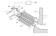
図1は、本発明による外付形の環状溶融金属用誘導電磁ポンプの一実施例である。この溶融金属用誘導電磁ポンプの構成は基本的に図8により前述した従来の電磁ポンプと同じであり、同じ部分は同じ符号を付してある。
溶融金属12を入れた溶融金属槽11の底部近くの斜めの壁面13に給湯口が開口しており、この給湯口にフランジ継手を介して真っ直ぐなポンプ側ダクト1が接続されている。この給湯側ダクト1は図1において左側の給湯方向に向けて次第に高くなるように傾斜し、給湯方向に向けて昇り勾配が形成されている。
FIG. 1 shows an embodiment of an external induction electromagnetic pump for molten metal according to the present invention. The structure of the induction electromagnetic pump for molten metal is basically the same as that of the conventional electromagnetic pump described above with reference to FIG. 8, and the same parts are denoted by the same reference numerals.
A hot water supply port is opened in an oblique wall surface 13 near the bottom of the
この真っ直ぐなポンプ側ダクト1の先端には、給湯側ダクト1’がフランジ継手等の継手5、5’を介して接続されている。この給湯用ダクト1’は、前記ポンプ側ダクト1とは逆に図1において左側の給湯方向に向けて次第に低くなるように傾斜し、給湯方向に向けて下り勾配が形成されている。そして、このポンプ側ダクト1と給湯側ダクト1’との接続部分の底部には、両側の勾配を分ける分湯嶺とも言うべき堰16が形成されている。この堰16を堺としてその両側のダクト1、1’の勾配が逆に切り替わる。ポンプ側ダクト1と給湯側ダクト1’の勾配をtanθとした場合、ポンプ側ダクト1と給湯側ダクト1’のθは±7゜以上であることが好ましい。
A hot water supply side duct 1 ′ is connected to the end of the straight pump side duct 1 via
このポンプ側ダクト1と給湯側ダクト1’との接続部分の上は蓋板19で閉じられている。この蓋板19には、前記堰16に向けてArガス、N2ガス等の不活性ガスを噴射するノズル17が設けられており、このノズル17には不活性ガスの供給源20が接続されている。また、蓋板19には窓が設けられ、この窓を通して金属の存在を検知する、例えばレーザセンサ等の金属表面との距離を側長するセンサ18が設けられている。このセンサにより金属の存在を検知する位置は前記堰より給湯側ダクト1’側にある部分である。
The top of the connection portion between the pump side duct 1 and the hot water supply side duct 1 ′ is closed by a
前記のダクト1、1’は、セラミック等の耐熱性、耐蝕性のある材料で作られている。図1に示すように、ダクト1、1’は、その周囲に設けた保温用のマイクロヒータ等からなるヒータ9が巻回され、同ヒータ9により溶融金属12の融点以上の温度に加熱され、ダクト1、1’の中の溶融金属12の温度低下による凝固を防ぐようになっている。なお、給湯側ダクト1’のヒータは図示を省略してあるが、ここにもヒータを設ける。
The ducts 1 and 1 'are made of a heat-resistant and corrosion-resistant material such as ceramic. As shown in FIG. 1, the duct 1, 1 ′ is wound around a
手前のポンプ側ダクト1の中には、その中心軸が一致するように磁性体製の円柱体からなるコア2が配置されている。このコア2は、両端が閉じられた円筒形の保護管3の中に収納されており、ポンプ側ダクト1内の溶融金属12と直接接触しないようになっている。コア2の保護管3は、セラミック等の耐熱性、耐蝕性のある材料で作られている。
In the pump-side duct 1 on the front side, a core 2 made of a cylindrical body made of a magnetic material is disposed so that its central axis coincides. The core 2 is accommodated in a cylindrical
保護管3の給湯側ダクト1’に近い一端部の周囲にフランジ6が延設され、このフランジ6の外周に近い部分が前記ポンプ側ダクト1と給湯側ダクト1’とを接続する継手5、5’の間に挟持されている。これにより、コア2がポンプ側ダクト1の中心に位置するよう保持されている。給湯側ダクト1’は、図示しないバネ等により手前のポンプ側ダクト1に押しつけられ、ガスケットにより継手5、5’の間に前記保護管3のフランジ6を挟持すると共に、シール性を確保している。
A flange 6 extends around one end of the
保護管3はセラミック等の成型体であるため、別部材としてフランジ6を設けるよりは、フランジ6を保護管3と一体に成型したものがよい。保護管3の中には、コア2を保護管3の中心に保持し、且つ運転時の振動によるがたつきを無くすため、クッション材としてアルミナ、マグネシア等のセラミック繊維或いはセラミック粉末等の充填材8が充填される。図1に示したように、図示の実施例では、保護管3の端部がセラミック等の耐熱性、耐蝕性のある端栓4により閉じられるようになっている。コア2や充填材8はこの端栓4を開けて保護管3の中に収納、充填される。
Since the
前記のフランジ6の継手5、5’に挟持された外周に近い部分より内周側の部分には、溶融金属を通すための通路7が設けられている。この通路7は、円周方向に長い長孔状のものであり、通路7の間は保護管3の本体部分である円筒部分とフランジ6の継手5、5’により挟持される外周側のリム状の部分とを一体に連絡するスポーク状の連結部となっている。この関係を示した斜視図が図7で、端詮4が取り付けられる前の図である。
A passage 7 for passing molten metal is provided in a portion closer to the inner periphery than a portion near the outer periphery sandwiched between the
図1に示すように、手前の真っ直ぐなポンプ側ダクト1の周囲には、磁性体製のヨークにコイルを巻回した円筒形状の誘導子14が配置されている。この誘導子14により、ポンプ側ダクト1の内部に移動磁界が形成され、ポンプ側ダクト1内の溶融金属に推力が与えられる。前記の磁性体製のコア2は、ポンプ側ダクト1の中心軸上に移動磁界の磁路を形成するもので、これにより、ポンプ側ダクト1内の移動磁界の磁束密度を維持し、ポンプ側ダクト1内での溶融金属の推力を確保する。
As shown in FIG. 1, a
次に、この環状溶融金属用誘導電磁ポンプの動作についてその運転方法も含めて説明する。
図1に示すように、誘導子14に通電していない運転休止時は、ポンプ側ダクト1の中にある溶融金属12の液面は、溶融金属槽11の溶融金属12の液面と同じ高さにある。この時のダクト1、1’の堰16と溶融金属12の液面との高さの差をh0とする。
Next, the operation of this induction molten metal induction pump including molten metal will be described.
As shown in FIG. 1, the liquid level of the
この状態から誘導子14に通電し、ポンプ側ダクト1の中に移動磁界を発生させて、その中の溶融金属12に推力を与え、図2(A)に示すように前記の給湯停止時の溶融金属12の定常液位−h0から堰16の高さを越えるhnの液位にすると、溶融金属12は堰16を越流し、給湯側ダクト1’側に流れ込み、溶融金属12の供給が行われる。
From this state, the
その後、誘導子14への通電を停止し、溶融金属12の供給を停止すると、ポンプ側ダクト1の溶融金属12の液面は、前述の定常液位−h0に戻る。これにより、ポンプ側ダクト1と給湯側ダクト1’にある溶融金属12は、それらの堰16を堺にそれぞれのダクト1、1’の勾配に沿って流れ落ち、堰16の両側に分離しようとする。しかし、両側へ均等に分離するのではなく、ポンプ側ダクト1の方が水力学的流路抵抗が大きい為、ポンプ側ダクト1への溶融金属12の戻りが遅くなって、給湯側ダクト1’に落ちて行く溶融金属12に引きずられて湯切れが悪くなる。このとき図2(B)に示すように、前記ノズル17からダクト1、1’の堰16に当たるように不活性ガスを噴出すると、堰16の頂部にある溶融金属12がその両側の上り勾配側と下り勾配側とに強制的に分離され、給湯側ダクト1’に流れ込む溶融金属12がポンプ側ダクト1にある溶融金属12と完全に遮断され、給湯側ダクト1’からの溶融金属12の供給が瞬時に停止される。
Thereafter, when energization to the
図3は、電磁ポンプの出力とノズル17からの不活性ガスの噴出との時間的関係を示すタイムチャートの例である。この図の通り、溶融金属の供給は、電磁ポンプの誘電子14への通電開始により始まり、電磁ポンプの誘電子14への通電停止により終了するが、このときノズル17から不活性ガスの噴出することで、前記のダクト1、1’の堰16における溶融金属の分離が行われる。
FIG. 3 is an example of a time chart showing the temporal relationship between the output of the electromagnetic pump and the ejection of the inert gas from the
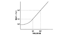
図4は、電磁ポンプ出力と溶融金属の単位時間当たりの流量との関係の例を示すグラフであり、電磁ポンプ出力は、ポンプ側ダクト1の溶融金属12の液位に換算して示してある。電磁ポンプ出力をhn=h1>h0と小さくした場合、溶融金属の単位時間当たりの流量はQ1と少なく、所定量の溶融金属の供給には時間がかかる。他方、電磁ポンプ出力をhn=h2>h0と大きくした場合、溶融金属の単位時間当たりの流量はQ2と多くなり、所定量の溶融金属の供給に時間がかからない。しかしながら、電磁ポンプ出力を大きくした場合、図5に示すように、溶融金属の単位時間当たりの流量の立ち上がりは急峻であるが、いわゆる過渡現象による供給流量の不安定な状態が生じる。そのため、このような過渡現象による供給流量の不安定な状態が出来るだけ小さくなるような電磁ポンプ出力を設定すべきである。
FIG. 4 is a graph showing an example of the relationship between the electromagnetic pump output and the flow rate of molten metal per unit time, and the electromagnetic pump output is shown in terms of the liquid level of the
なお前述の実施例では、ポンプ側ダクト1と給湯側ダクト1’とにそれぞれ逆勾配を設け、その間の底部に堰16を設けたが、例えば図6の様に給湯側ダクト1’を垂直な直管状とし、その一部に隆起した峰状の堰16を設けても同様の作用、効果が得られることは明らかである。当然堰16の両側に逆勾配が設けられるので、これにより供給する溶融金属を分離することが出来る。
In the above-described embodiment, the pump side duct 1 and the hot water supply side duct 1 ′ are provided with reverse gradients, and the
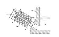
図6は本発明による溶融金属用電磁ポンプの他の実施例を示す断面図である。この溶融金属用電磁ポンプの構成は、基本的に図1に示したものと同様であり、同じ部分は同じ符合で示している。その同じ部分の説明は重複を避けるため、説明を省略し、異なる部分のみを説明する。 FIG. 6 is a sectional view showing another embodiment of the electromagnetic pump for molten metal according to the present invention. The structure of the molten metal electromagnetic pump is basically the same as that shown in FIG. 1, and the same portions are denoted by the same reference numerals. In order to avoid duplication of the description of the same part, description is omitted and only a different part is demonstrated.
この実施例による溶融金属用電磁ポンプではポンプ側ダクト1を溶融金属槽11の側面に水平に接続しており、このポンプ側ダクト1の先端には、給湯側ダクト1’がフランジ継手等の継手5、5’を介して接続されている。この給湯用ダクト1’は、垂直に立ち上がっており、その上端には給湯ブロック10が取り付けられている。この給湯ブロック10の底部には堰16が設けられており、この堰16の上面には給湯方向に向けて給湯側ダクト1’側に昇り勾配が、さらにその先の給湯側には下り勾配が形成されている。この堰16の頂部に向けてガスを噴出するノズル17が設けられている。
この溶融金属用電磁ポンプの運転方法は基本的には図1により説明した溶融金属用電磁ポンプと同じである。
In the molten metal electromagnetic pump according to this embodiment, the pump side duct 1 is connected horizontally to the side surface of the
The operation method of the molten metal electromagnetic pump is basically the same as the molten metal electromagnetic pump described with reference to FIG.
図8は、前記保護管3のフランジ6を含めた全体図である。この保護管3は、その端部にフランジ6を有しており、このフランジ6には溶融金属を通すための溶融金属通路7が開設されている。この保護管3は、基本的に図1により前述した溶融金属用電磁ポンプに使用されたものと同じである。
FIG. 8 is an overall view including the flange 6 of the
本発明による溶融金属用電磁ポンプとその運転方法では、定量の溶融金属を間欠的に供給する場合に、正確な供給量を確保することが可能となるので、ダイキャスト等の分野で精密鋳造のための溶融金属供給システムと適用が可能である。しかも、構造や制御も簡便であり、容易に実施出来るので、定量の溶融金属の間欠的な供給が容易に適用出来る。 In the electromagnetic pump for molten metal and its operation method according to the present invention, it is possible to ensure an accurate supply amount when supplying a certain amount of molten metal intermittently. It can be applied with molten metal supply system. Moreover, since the structure and control are simple and can be carried out easily, intermittent supply of a fixed amount of molten metal can be easily applied.
1 ポンプ側ダクト
1’ 給湯側ダクト
16 ダクトの底部の堰
17 ノズル
1 Pump side duct 1 'Hot water
Claims (3)
Priority Applications (1)
| Application Number | Priority Date | Filing Date | Title |
|---|---|---|---|
| JP2007160919A JP4986733B2 (en) | 2007-06-19 | 2007-06-19 | Electromagnetic pump for molten metal and its operation method |
Applications Claiming Priority (1)
| Application Number | Priority Date | Filing Date | Title |
|---|---|---|---|
| JP2007160919A JP4986733B2 (en) | 2007-06-19 | 2007-06-19 | Electromagnetic pump for molten metal and its operation method |
Publications (2)
| Publication Number | Publication Date |
|---|---|
| JP2009000689A JP2009000689A (en) | 2009-01-08 |
| JP4986733B2 true JP4986733B2 (en) | 2012-07-25 |
Family
ID=40317651
Family Applications (1)
| Application Number | Title | Priority Date | Filing Date |
|---|---|---|---|
| JP2007160919A Active JP4986733B2 (en) | 2007-06-19 | 2007-06-19 | Electromagnetic pump for molten metal and its operation method |
Country Status (1)
| Country | Link |
|---|---|
| JP (1) | JP4986733B2 (en) |
Families Citing this family (4)
| Publication number | Priority date | Publication date | Assignee | Title |
|---|---|---|---|---|
| JP4920061B2 (en) * | 2009-06-23 | 2012-04-18 | 助川電気工業株式会社 | Electromagnetic pump for molten metal and its operation method |
| JP5254168B2 (en) * | 2009-10-05 | 2013-08-07 | 助川電気工業株式会社 | Molten metal feeder |
| JP5787582B2 (en) * | 2011-04-12 | 2015-09-30 | 助川電気工業株式会社 | Molten metal filling device for die-cast sleeve |
| JP5767848B2 (en) * | 2011-04-18 | 2015-08-19 | 助川電気工業株式会社 | Molten metal hot water supply device for die-cast sleeve |
Family Cites Families (2)
| Publication number | Priority date | Publication date | Assignee | Title |
|---|---|---|---|---|
| JPH0649108Y2 (en) * | 1988-09-10 | 1994-12-12 | 助川電気工業株式会社 | Duct part of molten metal electromagnetic pump |
| JP3179284B2 (en) * | 1994-06-03 | 2001-06-25 | 宇部興産株式会社 | Magnesium water heater |
-
2007
- 2007-06-19 JP JP2007160919A patent/JP4986733B2/en active Active
Also Published As
| Publication number | Publication date |
|---|---|
| JP2009000689A (en) | 2009-01-08 |
Similar Documents
| Publication | Publication Date | Title |
|---|---|---|
| JP4986733B2 (en) | Electromagnetic pump for molten metal and its operation method | |
| JP4731810B2 (en) | Molten metal hot water furnace with metal treatment and liquid level control | |
| JP4989329B2 (en) | Molten metal electromagnetic pump and operation method thereof | |
| JP4920061B2 (en) | Electromagnetic pump for molten metal and its operation method | |
| JP2011131265A (en) | Vacuum die casting apparatus and vacuum die casting method | |
| TWI568520B (en) | Aluminum alloy hot room casting machine | |
| JP4966354B2 (en) | Casting equipment | |
| JP5787582B2 (en) | Molten metal filling device for die-cast sleeve | |
| CN107999721B (en) | Injection molding machine | |
| JP6131128B2 (en) | Die-cast sleeve molten metal supply device and method for supplying the same | |
| KR101367301B1 (en) | Flux feeding apparatus and molten mold flux feeding method | |
| KR101680919B1 (en) | Molten metal supply device and method for cleaning duct thereof | |
| JP2005205479A (en) | Soldering machine | |
| JP2009012024A (en) | Electromagnetic pump for molten metal | |
| KR101385008B1 (en) | Pour ladle for molten metal | |
| JP5113612B2 (en) | Induction electromagnetic pump for molten metal | |
| JP2011016166A (en) | Casting apparatus | |
| JP5459812B1 (en) | Semi-solid metal production container cooling device, semi-solid metal production device, semi-solid metal production method, and molding method using semi-solid metal | |
| JP6131147B2 (en) | Die-cast sleeve molten metal feeder | |
| JP5254168B2 (en) | Molten metal feeder | |
| JPH08141731A (en) | Casting method and casting device | |
| CN110944772B (en) | Casting mold and method for manufacturing casting | |
| JP2687315B2 (en) | Molten metal supply device | |
| RU2800935C2 (en) | Foundry equipment | |
| JP2015089564A (en) | Molten metal surface height control method of molten metal pouring tank of molten metal retaining furnace for low-pressure casting |
Legal Events
| Date | Code | Title | Description |
|---|---|---|---|
| A621 | Written request for application examination |
Free format text: JAPANESE INTERMEDIATE CODE: A621 Effective date: 20100525 |
|
| A977 | Report on retrieval |
Free format text: JAPANESE INTERMEDIATE CODE: A971007 Effective date: 20101202 |
|
| A131 | Notification of reasons for refusal |
Free format text: JAPANESE INTERMEDIATE CODE: A131 Effective date: 20120215 |
|
| A521 | Request for written amendment filed |
Free format text: JAPANESE INTERMEDIATE CODE: A523 Effective date: 20120229 |
|
| TRDD | Decision of grant or rejection written | ||
| A01 | Written decision to grant a patent or to grant a registration (utility model) |
Free format text: JAPANESE INTERMEDIATE CODE: A01 Effective date: 20120412 |
|
| A01 | Written decision to grant a patent or to grant a registration (utility model) |
Free format text: JAPANESE INTERMEDIATE CODE: A01 |
|
| A61 | First payment of annual fees (during grant procedure) |
Free format text: JAPANESE INTERMEDIATE CODE: A61 Effective date: 20120424 |
|
| R150 | Certificate of patent or registration of utility model |
Ref document number: 4986733 Country of ref document: JP Free format text: JAPANESE INTERMEDIATE CODE: R150 Free format text: JAPANESE INTERMEDIATE CODE: R150 |
|
| FPAY | Renewal fee payment (event date is renewal date of database) |
Free format text: PAYMENT UNTIL: 20150511 Year of fee payment: 3 |
|
| R250 | Receipt of annual fees |
Free format text: JAPANESE INTERMEDIATE CODE: R250 |
|
| R250 | Receipt of annual fees |
Free format text: JAPANESE INTERMEDIATE CODE: R250 |
|
| R250 | Receipt of annual fees |
Free format text: JAPANESE INTERMEDIATE CODE: R250 |