JP4984852B2 - Electric vacuum cleaner - Google Patents
Electric vacuum cleaner Download PDFInfo
- Publication number
- JP4984852B2 JP4984852B2 JP2006319857A JP2006319857A JP4984852B2 JP 4984852 B2 JP4984852 B2 JP 4984852B2 JP 2006319857 A JP2006319857 A JP 2006319857A JP 2006319857 A JP2006319857 A JP 2006319857A JP 4984852 B2 JP4984852 B2 JP 4984852B2
- Authority
- JP
- Japan
- Prior art keywords
- dust
- compression
- vacuum cleaner
- collection container
- electric blower
- Prior art date
- Legal status (The legal status is an assumption and is not a legal conclusion. Google has not performed a legal analysis and makes no representation as to the accuracy of the status listed.)
- Expired - Fee Related
Links
Images


Description
本発明は、電気掃除機に関するもので、特に、集塵容器内の塵埃を圧縮する機能を有する電気掃除機に関するものである。 The present invention relates to a vacuum cleaner, and more particularly to a vacuum cleaner having a function of compressing dust in a dust collecting container.
従来、この種の電気掃除機として、吸気通路を切り替えて電動送風機による負圧で集塵された塵埃を圧縮し、集塵量を向上させるようにしたものが提案されている(例えば、特許文献1参照)。
しかしながら、前記従来の電気掃除機の構成においては、吸気通路を切り替えて電動送風機からの負圧で塵埃を圧縮する構成であるため、圧縮する際には電動送風機の吸込み力
を上げ、負圧を大きくしないと圧縮効果が小さいため、圧縮を行うには大きな消費電力を必要としていた。また綿ゴミのような風量変化の小さい塵埃ではおおきな負圧がかからないため圧縮効果が小さいという課題を有していた。
However, in the configuration of the conventional vacuum cleaner, since the dust passage is compressed with the negative pressure from the electric blower by switching the intake passage, when the compression is performed, the suction force of the electric blower is increased to reduce the negative pressure. If it is not increased, the compression effect is small, so that a large amount of power is required to perform compression. In addition, dust having a small change in air volume, such as cotton dust, has a problem that the compression effect is small because a large negative pressure is not applied.
本発明は、上記従来の課題を解決するもので、塵埃容器に蓄積された塵埃を直接押圧して圧縮することで電動送風機の消費電力を抑え、かつ綿ゴミのような風量変化の小さい塵埃でもより確実に圧縮することができ、しかも、掃除前に集塵容器内に塵埃が入るスペースを十分確保したうえで掃除を行うことができる、使用性の高い電気掃除機を提供することを目的とする。 The present invention solves the above-described conventional problems, and suppresses the power consumption of the electric blower by directly pressing and compressing the dust accumulated in the dust container, and even dust having a small airflow change such as cotton dust. An object of the present invention is to provide a highly usable vacuum cleaner that can be more reliably compressed and that can be cleaned with sufficient space for dust to enter the dust collection container before cleaning. To do.
前記従来の課題を解決するために、本発明の電気掃除機は、吸引力を発生させる電動送風機と、塵埃を捕集する集塵容器と、前記電動送風機に連通すると共に前記集塵容器が着脱自在に装着される集塵容器収納部と、前記集塵容器内に配され捕集された前記塵埃を圧縮する圧縮手段と、前記圧縮手段を駆動する圧縮駆動手段と、前記圧縮駆動手段の動作を制御する制御手段と、前記電動送風機の運転モードを設定する運転操作部と、前記運転操作部に設けられ前記制御手段に操作信号を送る圧縮操作手段と、を備え、前記圧縮操作手段を手動で操作すると、前記制御手段に操作信号が送られ、前記制御手段は、前記圧縮駆動手段を動作させるもので、集塵容器に蓄積された塵埃を直接圧縮することで電動送風機の消費電力が抑えられて、電動送風機の寿命が延びる。また、綿ゴミのような風量変化の小さい塵埃でもより確実に圧縮することができる。
また、使用者が圧縮操作手段を操作したときだけしか圧縮動作が行われないため、圧縮回数が減り圧縮機構の信頼性が向上しさらに掃除時間を短縮することができる。
In order to solve the above-described conventional problems, an electric vacuum cleaner according to the present invention includes an electric blower that generates a suction force, a dust collecting container that collects dust, and the electric blower that is in communication with the dust collecting container. A dust collection container storage section that is freely mounted, a compression means for compressing the dust arranged and collected in the dust collection container, a compression drive means for driving the compression means, and an operation of the compression drive means A control means for controlling the operation, a driving operation section for setting an operation mode of the electric blower, and a compression operating means provided in the driving operation section for sending an operation signal to the control means. When the operation is performed, an operation signal is sent to the control means, and the control means operates the compression drive means, and the power consumption of the electric blower is suppressed by directly compressing the dust accumulated in the dust collecting container. Electric The life of the wind machine is extended. Also, dust with a small change in air volume such as cotton dust can be more reliably compressed.
Further, since the compression operation is performed only when the user operates the compression operation means, the number of compressions is reduced, the reliability of the compression mechanism is improved, and the cleaning time can be further shortened.
本発明の電気掃除機は、塵埃容器に蓄積された塵埃を直接圧縮することで電動送風機の消費電力を抑え、かつ綿ゴミのような風量変化の小さい塵埃でもより確実に圧縮することができる。さらに使用者が圧縮操作手段を操作したときだけしか圧縮動作が行われないため、圧縮回数が減り圧縮機構の信頼性が向上しさらに掃除時間を短縮することができる。 The electric vacuum cleaner of the present invention can directly compress dust accumulated in the dust container, thereby suppressing power consumption of the electric blower and more reliably compressing dust such as cotton dust that has a small change in air volume. Further , since the compression operation is performed only when the user operates the compression operation means, the number of compressions is reduced, the reliability of the compression mechanism is improved, and the cleaning time can be further shortened.
第1の発明は、吸引力を発生させる電動送風機と、塵埃を捕集する集塵容器と、前記電動送風機に連通すると共に前記集塵容器が着脱自在に装着される集塵容器収納部と、前記集塵容器内に配され捕集された前記塵埃を圧縮する圧縮手段と、前記圧縮手段を駆動する圧縮駆動手段と、前記圧縮駆動手段の動作を制御する制御手段と、前記電動送風機の運転モードを設定する運転操作部と、前記運転操作部に設けられ前記制御手段に操作信号を送る圧縮操作手段と、を備え、前記圧縮操作手段を手動で操作すると、前記制御手段に操作信号が送られ、前記制御手段は、前記圧縮駆動手段を動作させるもので、集塵容器に蓄積された塵埃を直接圧縮することで電動送風機の消費電力が抑えられて、電動送風機の寿命が延びる。また、綿ゴミのような風量変化の小さい塵埃でもより確実に圧縮することができる。また、使用者が圧縮操作手段を操作したときだけしか圧縮動作が行われないため、圧縮回数が減り圧縮機構の信頼性が向上しさらに掃除時間を短縮することができる。 The first invention includes an electric blower that generates a suction force, a dust collection container that collects dust, a dust collection container storage unit that communicates with the electric blower and is detachably attached to the dust collection container, Compression means for compressing the dust disposed and collected in the dust collection container, compression drive means for driving the compression means, control means for controlling the operation of the compression drive means , and operation of the electric blower A driving operation unit that sets a mode; and a compression operation unit that is provided in the driving operation unit and sends an operation signal to the control unit. When the compression operation unit is manually operated, an operation signal is sent to the control unit. The control means operates the compression driving means. By directly compressing the dust accumulated in the dust collecting container, the power consumption of the electric blower is suppressed, and the life of the electric blower is extended. Also, dust with a small change in air volume such as cotton dust can be more reliably compressed. Further, since the compression operation is performed only when the user operates the compression operation means, the number of compressions is reduced, the reliability of the compression mechanism is improved, and the cleaning time can be further shortened.
以下、本発明の実施の形態について、図面を参照しながら説明する。なおこの実施の形態によって本発明が限定されるものではない。 Hereinafter, embodiments of the present invention will be described with reference to the drawings. The present invention is not limited to the embodiments.
(実施の形態1)
本発明の第1の実施の形態における電気掃除機について、図1〜図7を用いて説明する。図1は、本実施の形態における電気掃除機の全体斜視図、図2は、同電気掃除機の側断面図である。
(Embodiment 1)
The vacuum cleaner in the 1st Embodiment of this invention is demonstrated using FIGS. FIG. 1 is an overall perspective view of the vacuum cleaner according to the present embodiment, and FIG. 2 is a side sectional view of the vacuum cleaner.
図1、2において、掃除機本体1は、後部に電動送風機2を内蔵した電動送風機室3が配され、前部に、塵埃を分離捕集する集塵容器4を着脱自在に収納する集塵容器収納部5が配されている。掃除機本体1の前部には、ホース6の一端が着脱自在に接続される吸気口7が設けられている。ホース6の他端には、掃除の際に握ると共に掃除機本体1の運転を操作するための運転操作部8を備えた先端パイプ9が設けられている。10は、伸縮自在或いは継ぎ自在の延長管で、下流側端部が前記先端パイプ9に着脱自在に接続され、他端は、床用吸込具11に着脱自在に接続される。70は、掃除機本体1に電源を供給するための電源コードで、先端に電源プラグ71が設けられている。
1 and 2, the vacuum cleaner
本実施の形態における電気掃除機は、電動送風機2の運転モードとして、「強」運転モード、「弱」運転モード、「自動」運転モードを備えており、運転操作部8には、上記運転モードを切りえる又は運転モードを選択するためのスイッチ(図示せず)と、電動送風機2の運転を停止させるための停止操作手段となる「切り」スイッチ(図示せず)が配されている。
The vacuum cleaner in the present embodiment includes a “strong” operation mode, a “weak” operation mode, and an “automatic” operation mode as operation modes of the
12は、集塵容器4の持ち運び用の容器ハンドルで、集塵容器4を持ち運ぶ時や、掃除機本体1の集塵容器収納部5から取り外す時に、握るものである。
A container handle 12 for carrying the dust collection container 4 is gripped when the dust collection container 4 is carried or removed from the dust
次に、集塵容器4の構成について図3〜6を用いて説明する。図3は、同電気掃除機の集塵容器の一部欠載斜視図、図4は、同集塵容器の断面図、図5は、同集塵容器と集塵容器収納部の斜視図、図6は、同集塵容器の裏面斜視図である。 Next, the configuration of the dust collecting container 4 will be described with reference to FIGS. FIG. 3 is a perspective view of a part of the dust collecting container of the vacuum cleaner, FIG. 4 is a sectional view of the dust collecting container, and FIG. 5 is a perspective view of the dust collecting container and the dust collecting container storage unit. FIG. 6 is a rear perspective view of the dust collecting container.
図3〜6において、集塵容器4は、集塵容器本体15と、集塵容器本体15の後方開口部に着脱自在に装着されるフィルターユニット16から構成されている。
3 to 6, the dust collection container 4 includes a dust collection container
集塵容器本体15の前部には、集塵容器4を、掃除機本体1の集塵容器収納部5に装着した時に、掃除機本体1の吸気口7の後方に気密に圧接し連通する吸入口17が設けられている。集塵容器本体15は、さらに、吸入口17に直接連通すると共に粗塵を収納する粗塵室18と、粗塵室18を通過した吸引風に含まれた細塵を捕集するフィルターユニット16から離脱した細塵を収納する細塵室19と、前記粗塵室18と細塵室19の下部開口を覆うと共に後方端部が、集塵容器本体15に回動自在に軸支された蓋体20を備えている。
When the dust container 4 is attached to the front part of the
蓋体20は、コイルバネ21により開成方向に付勢されており、通常は、集塵容器本体15に設けた尾錠22で、その前部が閉じた状態に保持されており、容器ハンドル12の前部に設けた操作部23を押すと、それに連結された連結棒C46を介して尾錠22を外方に移動させ、蓋体20が、コイルバネ21の付勢力で開くようになっている。なお、25は、バネ材で、操作部23を常時上方に付勢するためのものである。
The
粗塵室18の、吸入口17と連通する部分を除く全内周壁(4側壁)は、下部開口26に向かって次第に広がる傾斜面27を有する一次フィルターA28で形成されている。又、粗塵室18の上部には、上下動自在の連結棒A24の下端に固着されると共に、一次フィルターB29を有した圧縮板30が配されている。この圧縮板30は、粗塵室18内に捕集された塵埃を押さえつけて圧縮する圧縮手段となるものである。
The entire inner peripheral wall (four side walls) of the
連結棒A24の上端には、略L字状のスライダー31の一端が固着されている。スライダー31の上下方向の側部には、ラックギア31aが形成されている。32は、連結棒A24を常時上方に、すなわち圧縮板30を常時上方に付勢する弾性部材からなるスライダーバネである。33は、集塵容器4の側部に回転自在に支持された駆動軸で、後端にギヤ
B35を有し、さらに、ギヤ群39を介してラックギヤ31aに動力を伝達するためのギヤD37を備えている。
One end of a substantially L-
47は、集塵容器4の側部に回転自在に支持された駆動軸Bで、後方にギヤF48を有し、後述のギヤA34に噛み合うギヤC36を備えている。
一方、掃除機本体1内の電動送風機室3と集塵容器収納部5とを仕切る隔壁40には、集塵容器4を集塵容器収納部5に装着したときに、ギヤB35が噛み合うと共に、圧縮駆動モータ56で回転駆動されるギヤE38を収納するギヤ収納部41が設けられている。また、隔壁40には、ギヤF48に噛み合うと共に、除塵駆動モータ61で回転駆動されるギヤG49を備えている。
On the other hand, when the dust container 4 is attached to the dust
フィルターユニット16は、図6に示すように、枠体42と、プリーツ折りされ、そのプリーツ目を縦方向にして枠体42に設けられた二次フィルター43と、横方向に摺動自在に設けられ除塵手段である弾き体44と、フィルターユニット16の側部に回転自在に設けられたギヤA34と、前記ギヤA34の外周部と弾き体44の一部とを連結する連結棒B45とから構成されている。さらに、弾き体44の二次フィルター43と対向する面には、プリーツ折りされた二次フィルター43の各山折り部に当接する突起(図示せず)が設けられている。
As shown in FIG. 6, the
上記構成により、ギヤA34が回転すると、連結棒B45を介して連結された弾き体44が左右に往復移動すると共に、その間に、弾き体44に設けた突起が、二次フィルター43の山折り部を弾き、その時に生じる振動やショックで、二次フィルター43の裏面(粗塵室18側の面)に付着した細塵がふるい落とされ、細塵室19に溜まると共に、二次フィルター43の濾過性能が復活するようになっている。
With the above configuration, when the gear A34 rotates, the
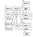
次に、図7を用いて、本実施の形態における電気掃除機の制御システムについて、説明する。 Next, the control system of the vacuum cleaner in this Embodiment is demonstrated using FIG.
図7において、51は、掃除機本体1が商用電源(図示せず)に接続され、通電されたかどうかを検知する通電検知手段である。
In FIG. 7, 51 is an energization detection means for detecting whether the
52は、マイクロコンピュータなどにより構成される制御手段で、使用者によって運転操作部8より入力された操作情報に基づき、電動送風機2を駆動する駆動手段54へ信号を出力したり、操作情報や通電検知手段51の検知情報に基づき、圧縮板30を駆動する圧縮駆動手段55へ信号を出力する制御手段である。
圧縮駆動手段55は、ギヤE38を回駆動する圧縮駆動モータ56を使用して、Hブリッチ等で構成し、正回転動作、逆回転動作を行い、圧縮板30の上下動を実現している。57は、商用電源からスイッチング等で得られたDC電源で、圧縮駆動モータ56を駆動するための電源となるものである。
The compression drive means 55 is composed of an H-bitch and the like using a
53は、圧縮駆動モータ56に加わる負荷量を検出する負荷量検出手段で、本実施の形態では、圧縮駆動モータ56に流れる電流の増減を検出して圧縮駆動モータ56に加わる負荷量を検出するようにしている。
使用者は、運転操作部8により、掃除機本体1を、「強」運転、「弱」運転、「自動」運転、「切」などの運転操作を行うことができる。
The user can perform operation operations such as “strong” operation, “weak” operation, “automatic” operation, “off”, and the like on the vacuum cleaner
除塵駆動手段60は、ギヤG49を回転駆動する除塵駆動モータ61などから構成され
、制御手段52からの信号を受けて、弾き体44を駆動している。
The dust removal driving means 60 is constituted by a dust
62は、集塵容器4本体が、集塵容器収納部5に収納されていることを検知する、例えばマイクロスイッチなどで構成された集塵容器検出手段である。
上記のように構成された本実施の形態における電気掃除機の動作、作用は以下の通りである。 The operation and action of the vacuum cleaner in the present embodiment configured as described above are as follows.
電気掃除機の使用開始に当たり、使用者が、掃除機本体1の電源プラグ70を室内の壁に設けたコンセント(図示せず)に差すと、通電検知手段51が、掃除機本体1に通電されたことを検知し、制御手段52に信号を送る。制御手段52は、正回転で回転するように圧縮駆動手段55に信号を送り、ギヤE38を回転駆動する圧縮駆動モータ56を駆動するとともに、除塵駆動手段60に信号を送り、ギヤG49を回転駆動する除塵駆動モータ61を駆動する。
When the user starts using the vacuum cleaner, when the user inserts the
そして、ギヤE38が回転することによって、圧縮駆動モータ56の回転動力が、駆動軸33に取り付けられたギヤD37を介して、ラックギヤ31aに伝達され、圧縮板30が下降して塵埃を圧縮する。そして、前記圧縮板30が、粗塵室18内に堆積された塵埃を圧縮しながら、下降していくと、次第に、圧縮駆動モータ56に加わる負担が増加し、それに伴い、圧縮駆動モータ56に流れる電流が次第に増加し、負荷量検出手段53が検出する負荷量が所定の負荷量を超えると、圧縮駆動手段55が、粗塵室18内の塵埃が十分圧縮されたと判断し、圧縮駆動モータ56の回転方向を反転させる。そして、圧縮板30が最初の原点位置まで戻ると、圧縮駆動モータ56が拘束されるため負荷電流が増加し負荷量検出手段53で原点に戻ってきたことを判断し、圧縮駆動モータ56を停止させる。この一連の動作は、あらかじめ設定した回数内で行われる。
As the gear E38 rotates, the rotational power of the
上記圧縮動作と同時に、除塵駆動モータ61の回転動力が、駆動軸B47に取り付けられたギヤC36を介して、ギヤA34に伝達され、弾き体44が左右に往復移動し、その間に、二次フィルター43の山折り部を弾いて、二次フィルター43の裏面に付着した細塵をふるい落とす動作が、あらかじめ設定した時間内で行なわれる。
Simultaneously with the compression operation, the rotational power of the dust
この圧縮動作が行なわれている間に、使用者が掃除動作を行うために、運転操作部8の「自動」を操作したときは、圧縮動作がどの状態であっても、圧縮駆動モータ56を原点位置に戻す回転方向で動作させ、圧縮板30が最初の原点位置まで戻ったことを判断し、圧縮駆動モータ56を停止させ、同タイミングで除塵駆動モータ61も停止させた後、「自動」ポジションで掃除動作が開始される。
While the compression operation is being performed, when the user operates “automatic” of the driving
電気掃除機の運転を開始すると、制御手段52は、駆動手段54に信号を送り、電動送風機2を運転させる。この電動送風機2による吸引力が、二次フィルター43、一次フィルターA28および一次フィルターB29、粗塵室18、ホース6、延長管10を経て床用吸込具11に至る。そして、床用吸込具11から吸引された塵埃を含んだ空気が、掃除機本体1の吸気口7を通って集塵容器本体15の吸入口17から真っ直ぐ粗塵室18に入り、一次フィルターA28及び一次フィルターB29に当たりそこで塵埃が捕集され、堆積していく。一次フィルターA28および一次フィルターB29を通過した空気に含まれる微細塵は、二次フィルター43で捕捉される。
When the operation of the electric vacuum cleaner is started, the
掃除動作が終了し使用者が、運転操作部8で「停止」操作を行うと、まず除塵動作を所定時間先に行って細塵のふるい落としを行った後に圧縮動作を行う。このとき時間を短縮するために圧縮動作も、停止操作直後に除塵動作と同時に行ったり、停止操作から予め設定している所定時間経過後に除塵動作と圧縮動作を同時に行ってもよいことは言うまでも
ない。この塵埃圧縮中に、使用者が再度「自動」を操作したときには電源投入時と同じで原点位置に戻してから掃除動作を行い、圧縮中に使用者が、運転操作部8で、「停止」を操作したときには原点に戻してから圧縮動作、除塵動作を停止させるように動作する。
When the cleaning operation is completed and the user performs a “stop” operation at the
次に、集塵容器4内に圧縮されて堆積した塵埃の廃棄について説明する。 Next, disposal of dust that has been compressed and accumulated in the dust container 4 will be described.
集塵容器4を集塵容器収納部5から取り外す時は、容器ハンドル12を握って集塵容器4を上方に持上げるだけで良い。そして、集塵容器4をごみ箱などの上に持っていって、容器操作部23を押すと、連結棒C46が下がって、尾錠22が外方に移動して、蓋体20と尾錠22との係止が解除され、蓋体20がコイルバネ21の付勢力で開成し、集塵容器4内の圧縮された塵埃や細塵がごみ箱内に落下する。
When removing the dust collection container 4 from the dust collection
以上のように、本実施の形態によれば、電源投入後から電動送風機2の動作までに少なくとも1回は、圧縮駆動手段55を動作させることにより、集塵容器4に蓄積された塵埃を直接押圧して圧縮することで、綿ゴミのような風量変化の小さい塵埃でもより確実に圧縮することができる。さらに圧縮するタイミングを、電源投入時とすることで掃除前に集塵容器4に塵埃が入るスペースを確保したうえで掃除が行えるため、掃除を行ってすぐに塵埃を捨てる必要もなくなり、使い勝手が向上する。
As described above, according to the present embodiment, the dust accumulated in the dust collecting container 4 is directly removed by operating the compression driving means 55 at least once after the power is turned on until the operation of the
また、停止操作後、所定時間経過後に圧縮駆動手段55を動作させることにより、集塵されたすべての塵埃を圧縮し、固めることでごみ捨てを容易に行うことができる。 Further, by operating the compression driving means 55 after a lapse of a predetermined time after the stop operation, all the collected dust can be compressed and hardened to easily dispose of garbage.
さらに、二次フィルター43を除塵する弾き体44を設けたので、適宜二次フィルター43の濾過性能を復活させることができ、掃除運転の終了後は、まず、除塵動作を先に行ってから圧縮動作をするようにすれば、細塵の舞い上がりを抑制し、塵埃としてまとめることができる。
Further, since the
又、圧縮動作中に、運転操作部8が操作されると、圧縮動作は初期化され、原点に戻してから次動作に移行することにより、掃除を行いたいときにすぐに掃除動作が出来たり、別の部屋に掃除移動する際等に圧縮動作をしないで停止させるようにすることで、使用者が圧縮動作を必要としないときには圧縮動作が行われないようにすることができ、圧縮回数が減り圧縮機構の信頼性が向上しさらに掃除時間を短縮することができる。
In addition, if the
上記実施の形態では、圧縮動作中に使用者が、掃除を行なうために、運転操作部8で例えば、「自動」を選択した場合は、圧縮動作がどの状態であっても、圧縮板30を最初の原点位置まで戻すようにしたが、圧縮動作を行ってから、圧縮板30を最初の原点位置まで戻して圧縮駆動モータ56を停止させ、同タイミングで除塵駆動モータ61も停止させた後、「自動」ポジションで掃除動作を開始するようにしても良い。
In the above-described embodiment, when the user selects, for example, “automatic” in the
また運転停止後の塵埃圧縮中の手元操作も同様に、使用者が再度「自動」を操作したときには、圧縮動作を完了させて原点位置に戻してから、掃除動作を行い、塵埃圧縮中に使用者が「停止」を操作したときには、圧縮動作が終了して原点に戻してから圧縮動作、除塵動作を停止させるようにしても良い。 Similarly, when the user operates “Automatic” again after the operation is stopped, the compression operation is completed and returned to the home position, and then the cleaning operation is performed and the dust operation is used. When the operator operates “stop”, the compression operation and the dust removal operation may be stopped after the compression operation is completed and returned to the origin.
以上のようにすることにより、常に圧縮動作が完了した後に、次動作に移行することになり、確実に圧縮動作が行われ、集塵容器4に塵埃が入るスペースを十分確保したうえで掃除が行え、さらに集塵された塵埃が固められるのでごみ捨てを容易に行うことができる。 By doing as described above, after the compression operation is always completed, the operation proceeds to the next operation, the compression operation is surely performed, and the dust collection container 4 has a sufficient space for dust to be cleaned. Moreover, since the collected dust is hardened, it is possible to easily dispose of garbage.
塵埃圧縮中の運転操作部8の操作を無効とし、圧縮動作が終了してからの操作で動作に
移行するようにしても同様の効果を得られることは言うまでもない。
It goes without saying that the same effect can be obtained even if the operation of the driving
(実施の形態2)
図8は、本発明の第2の実施の形態における電気掃除機の制御内容を示すブロック図である。なお、上記第1の実施の形態における電気掃除機と同一部分については、同一符号を付してその説明を省略する。
(Embodiment 2)
FIG. 8 is a block diagram showing the control content of the electric vacuum cleaner according to the second embodiment of the present invention. In addition, about the same part as the vacuum cleaner in the said 1st Embodiment, the same code | symbol is attached | subjected and the description is abbreviate | omitted.
本実施の形態は、図8に示すように、使用者が、必要に応じて、圧縮駆動手段55を動作させて、集塵容器4内の塵埃を圧縮できるように、運転操作部8に、操作したときに制御手段52に信号を送る圧縮操作手段63を設けたものである。 In the present embodiment, as shown in FIG. 8, the user can operate the compression drive means 55 to compress the dust in the dust collecting container 4 as necessary. A compression operation means 63 is provided for sending a signal to the control means 52 when operated.
以上のように構成された電気掃除機について、以下その動作、作用を説明する。 About the vacuum cleaner comprised as mentioned above, the operation | movement and an effect | action are demonstrated below.
使用者が掃除を行う前に、通気経路を確保したいときや、ごみ捨てを行いたいときに圧縮操作手段63を操作すると、圧縮操作手段63より制御手段52に操作信号が送られ、制御手段52は、その操作信号を検出して、圧縮駆動手段55を動作させて、圧縮動作を行う。 If the compression operation means 63 is operated when the user wants to secure a ventilation path or wants to dispose of garbage before cleaning, an operation signal is sent from the compression operation means 63 to the control means 52, and the control means 52 The operation signal is detected, and the compression driving means 55 is operated to perform the compression operation.
以上のように、本実施の形態によれば、圧縮操作手段63が操作されたときに圧縮駆動手段55が動作することにより、使用者が、塵埃を圧縮したいときだけしか圧縮動作が行われないため、圧縮回数が減り圧縮機構の信頼性が向上しさらに掃除時間を短縮することができる。 As described above, according to the present embodiment, the compression driving means 55 operates when the compression operation means 63 is operated, so that the compression operation is performed only when the user wants to compress dust. Therefore, the number of compressions is reduced, the reliability of the compression mechanism is improved, and the cleaning time can be further shortened.
以上のように、本発明にかかる電気掃除機は、蓄積された塵埃を圧縮して、集塵容器に多くの塵埃を集塵して、塵埃を捨てる回数を少なくすることができるもので、家庭用、業務用の各種電気掃除機に特に有用である。 As described above, the vacuum cleaner according to the present invention compresses accumulated dust, collects a large amount of dust in a dust collecting container, and reduces the number of times the dust is discarded. It is particularly useful for various vacuum cleaners for business use and business use.
1 掃除機本体
2 電動送風機
4 集塵容器
5 集塵容器収納部
15 集塵容器本体
30 圧縮板(圧縮手段)
44 弾き体(除塵手段)
52 制御手段
53 負荷量検出手段
55 圧縮駆動手段
56 圧縮駆動モータ
61 除塵駆動モータ
DESCRIPTION OF
44 Play body (dust removal means)
52 Control means 53 Load amount detection means 55 Compression drive means 56
Claims (1)
Priority Applications (1)
| Application Number | Priority Date | Filing Date | Title |
|---|---|---|---|
| JP2006319857A JP4984852B2 (en) | 2006-11-28 | 2006-11-28 | Electric vacuum cleaner |
Applications Claiming Priority (1)
| Application Number | Priority Date | Filing Date | Title |
|---|---|---|---|
| JP2006319857A JP4984852B2 (en) | 2006-11-28 | 2006-11-28 | Electric vacuum cleaner |
Publications (2)
| Publication Number | Publication Date |
|---|---|
| JP2008132110A JP2008132110A (en) | 2008-06-12 |
| JP4984852B2 true JP4984852B2 (en) | 2012-07-25 |
Family
ID=39557376
Family Applications (1)
| Application Number | Title | Priority Date | Filing Date |
|---|---|---|---|
| JP2006319857A Expired - Fee Related JP4984852B2 (en) | 2006-11-28 | 2006-11-28 | Electric vacuum cleaner |
Country Status (1)
| Country | Link |
|---|---|
| JP (1) | JP4984852B2 (en) |
Family Cites Families (4)
| Publication number | Priority date | Publication date | Assignee | Title |
|---|---|---|---|---|
| JPS54119272U (en) * | 1978-02-10 | 1979-08-21 | ||
| JPS5558137A (en) * | 1978-10-25 | 1980-04-30 | Tokyo Electric Co Ltd | Vacuum cleaner |
| JPH10117979A (en) * | 1996-10-21 | 1998-05-12 | Tec Corp | Vacuum cleaner |
| JP2005198754A (en) * | 2004-01-14 | 2005-07-28 | Matsushita Electric Ind Co Ltd | Vacuum cleaner |
-
2006
- 2006-11-28 JP JP2006319857A patent/JP4984852B2/en not_active Expired - Fee Related
Also Published As
| Publication number | Publication date |
|---|---|
| JP2008132110A (en) | 2008-06-12 |
Similar Documents
| Publication | Publication Date | Title |
|---|---|---|
| TWI342198B (en) | ||
| AU2007200171B2 (en) | Vacuum cleaner filter cleaning mechanisms | |
| JP4205466B2 (en) | Electric vacuum cleaner | |
| CA2618445C (en) | Dust compressing apparatus of vacuum cleaner | |
| EP1987756A2 (en) | Dust compressing apparatus of vacuum cleaner | |
| KR20220010298A (en) | Cleaner | |
| JP2008073066A (en) | Electric vacuum cleaner | |
| JP4984852B2 (en) | Electric vacuum cleaner | |
| JP4984877B2 (en) | Electric vacuum cleaner | |
| JP4940873B2 (en) | Electric vacuum cleaner | |
| JP4984853B2 (en) | Electric vacuum cleaner | |
| JP5040344B2 (en) | Electric vacuum cleaner | |
| CN211093737U (en) | Vacuum cleaner with a vacuum cleaner head | |
| JP5040454B2 (en) | Electric vacuum cleaner | |
| JP4983225B2 (en) | Electric vacuum cleaner | |
| JP2012024173A (en) | Vacuum cleaner | |
| CN112438648A (en) | Vacuum cleaner with a vacuum cleaner head | |
| JP2008113788A (en) | Vacuum cleaner | |
| JP4066718B2 (en) | Electric vacuum cleaner | |
| JP2012235865A (en) | Vacuum cleaner | |
| JP4952199B2 (en) | Electric vacuum cleaner | |
| JP2008289764A (en) | Vacuum cleaner | |
| JP2012249822A (en) | Vacuum cleaner | |
| US20240138638A1 (en) | Vacuum cleaning device | |
| US20240138639A1 (en) | Vacuum cleaning device |
Legal Events
| Date | Code | Title | Description |
|---|---|---|---|
| A621 | Written request for application examination |
Free format text: JAPANESE INTERMEDIATE CODE: A621 Effective date: 20091021 |
|
| RD01 | Notification of change of attorney |
Free format text: JAPANESE INTERMEDIATE CODE: A7421 Effective date: 20091112 |
|
| A977 | Report on retrieval |
Free format text: JAPANESE INTERMEDIATE CODE: A971007 Effective date: 20111028 |
|
| A131 | Notification of reasons for refusal |
Free format text: JAPANESE INTERMEDIATE CODE: A131 Effective date: 20111101 |
|
| A521 | Written amendment |
Free format text: JAPANESE INTERMEDIATE CODE: A523 Effective date: 20111226 |
|
| TRDD | Decision of grant or rejection written | ||
| A01 | Written decision to grant a patent or to grant a registration (utility model) |
Free format text: JAPANESE INTERMEDIATE CODE: A01 Effective date: 20120403 |
|
| A01 | Written decision to grant a patent or to grant a registration (utility model) |
Free format text: JAPANESE INTERMEDIATE CODE: A01 |
|
| A61 | First payment of annual fees (during grant procedure) |
Free format text: JAPANESE INTERMEDIATE CODE: A61 Effective date: 20120416 |
|
| FPAY | Renewal fee payment (event date is renewal date of database) |
Free format text: PAYMENT UNTIL: 20150511 Year of fee payment: 3 |
|
| LAPS | Cancellation because of no payment of annual fees |