JP4984793B2 - Bookbinding apparatus and image forming system - Google Patents
Bookbinding apparatus and image forming system Download PDFInfo
- Publication number
- JP4984793B2 JP4984793B2 JP2006264339A JP2006264339A JP4984793B2 JP 4984793 B2 JP4984793 B2 JP 4984793B2 JP 2006264339 A JP2006264339 A JP 2006264339A JP 2006264339 A JP2006264339 A JP 2006264339A JP 4984793 B2 JP4984793 B2 JP 4984793B2
- Authority
- JP
- Japan
- Prior art keywords
- adhesive
- temperature
- application
- heater
- temperature sensor
- Prior art date
- Legal status (The legal status is an assumption and is not a legal conclusion. Google has not performed a legal analysis and makes no representation as to the accuracy of the status listed.)
- Active
Links
Images


Landscapes
- Folding Of Thin Sheet-Like Materials, Special Discharging Devices, And Others (AREA)
Description
本発明は、複数枚のシートを集積してシート束を生成し、シート束と表紙を接着剤により接合させて製本する製本装置及び画像形成システムに関するものである。 The present invention relates to a bookbinding apparatus and an image forming system for stacking a plurality of sheets to generate a sheet bundle, and binding the sheet bundle and a cover sheet with an adhesive.
複写機やプリンタ等で画像を形成した複数枚のシートを簡易的に製本処理する製本装置及び画像形成システムが知られている。製本装置等における一般的な製本処理の概要を説明すると、まず画像を形成した複数枚のシートを集積・整合してシート束を生成する。次にシート束の一辺に糊等の接着剤を塗布する。そして表紙を搬送させて所定位置に停止させ、表紙をシート束の接着剤塗布面に接合する。このような手順で複数枚のシートと表紙が一体となり本が形成されるのである。 2. Description of the Related Art A bookbinding apparatus and an image forming system for simply bookbinding a plurality of sheets on which images are formed by a copying machine or a printer are known. An outline of a general bookbinding process in a bookbinding apparatus or the like will be described. First, a plurality of sheets on which images are formed are accumulated and aligned to generate a sheet bundle. Next, an adhesive such as glue is applied to one side of the sheet bundle. Then, the cover sheet is conveyed and stopped at a predetermined position, and the cover sheet is bonded to the adhesive-coated surface of the sheet bundle. In such a procedure, a plurality of sheets and a cover are integrated to form a book.
ところでシート束と表紙を接合させる接着剤の多くは、固形の接着剤をヒータで溶融させた接着剤(ホットメルト接着剤)である。このような接着剤により製本処理を実行するためには、固形の接着剤を劣化させないように加熱し、迅速に溶融させる必要がある。 By the way, most of the adhesives for joining the sheet bundle and the cover are adhesives (hot melt adhesives) in which a solid adhesive is melted with a heater. In order to perform the bookbinding process using such an adhesive, it is necessary to heat and quickly melt the solid adhesive so as not to deteriorate.
特許文献1に記載の技術は接着剤を溶融させるヒータの加熱温度を気温に反比例した値として自動的に設定するという技術である。この技術によれば環境を考慮して、固形の接着剤を劣化させないように適切に加熱し、迅速に溶融させることが出来る。
製本処理を多数回実行する場合は、それだけ多くの接着剤が必要である。そこで図12に示すように一定量の接着剤2000を製本装置内に収容し、塗布ローラ3000により接着剤をシート束の一辺に塗布する機構が考えられる。図12に示す機構を詳しく説明すると、一定量の接着剤2000は接着剤収容部1000に収容されている。接着剤収容部1000の下部には第一のヒータ4000が設置されており、塗布ローラ3000の内部には第二のヒータ3001が設置されている。2つのヒータにより接着剤2000を上下から加熱し、接着剤2000は溶融している。接着剤2000が付着した塗布ローラ3000は図示しないシート束の一辺に沿って移動し、シート束の一辺に接着剤が塗布される。
If the bookbinding process is performed many times, so much adhesive is required. Therefore, as shown in FIG. 12, a mechanism is conceivable in which a certain amount of
接着剤収容部1000内の接着剤2000は、製本装置の電源がOFFされ2つのヒータもOFFされると温度が低下してしまい、適正な溶融状態とは異なる状態になってしまう。そこで、製本装置の電源がONされたら2つのヒータより接着剤2000を迅速に加熱し、製本処理が出来るよう接着剤2000を適正な溶融状態にする必要がある。
The
接着剤2000が適正な溶融状態になったかどうかは接着剤2000の温度を検知して判断することが考えられる。しかし、一定量の接着剤2000を収容する接着剤収容部1000では接着剤収容部内の位置により接着剤の温度が異なるため、どの位置に温度センサを設置して接着剤の温度を検知し、接着剤全体として適正な溶融状態になっていることを判断するかということが問題となる。
It can be considered that the temperature of the
第一のヒータ4000の周辺であるα領域に温度センサを設置して接着剤の温度を検知する場合、α領域の接着剤の温度が適正な温度だとしても接着剤収容部1000の上部のβ領域にある接着剤の温度が適正な温度になっているとは限らない。従ってその状態で塗布ローラ3000を回転させて接着剤の塗布動作を開始すると、塗布ローラ3000の回転に対して溶融していない接着剤が負荷となり、塗布ローラ3000の回転が停止しまう可能性がある。場合によっては塗布ローラ3000の駆動モータ等が故障してしまう。
When a temperature sensor is installed in the α region around the
一方、接着剤収容部1000の上部であるβ領域に温度センサを設置して接着剤の温度を検知する場合、β領域の接着剤が適正な温度になったときにα領域の接着剤が第一のヒータ4000により過剰に加熱されて接着剤の劣化が進んでしまう可能性がある。
On the other hand, when a temperature sensor is installed in the β region, which is the upper part of the
従って、本発明の目的は、一定量の接着剤を収容する場合であっても接着剤の溶融状態を適正に判断してシート束への接着剤の塗布動作を開始する製本装置及び画像形成システムを提供することにある。 Accordingly, an object of the present invention is to provide a bookbinding apparatus and an image forming system for appropriately determining the melted state of the adhesive and starting the operation of applying the adhesive to the sheet bundle even when a certain amount of adhesive is accommodated. Is to provide.
上記目的を達成すべく、本発明に係る製本装置は、複数枚のシートを集積してシート束を生成し、当該シート束と表紙を接着剤により接合させて製本する製本装置であって、溶融した接着剤を収容する接着剤収容部と、当該接着剤収容部の下部に設置され、前記接着剤収容部に収容された接着剤を加熱する収容部ヒータと、当該収容部ヒータの上方に設置され、前記接着剤収容部に収容された接着剤を前記シート束の一端側に塗布する塗布手段と、当該塗布手段に設置され、前記接着剤収容部に収容された接着剤を加熱する塗布手段ヒータと、鉛直方向において前記収容部ヒータと前記塗布手段ヒータとの中間に設置され、前記接着剤収容部に収容された接着剤の温度を検知する接着剤温度センサと、前記接着剤温度センサにより検知した接着剤の温度が所定温度に達していない場合、前記塗布手段による接着剤塗布動作を禁止し、前記接着剤温度センサにより検知した接着剤の温度が所定温度に達した場合、前記塗布手段による接着剤塗布動作を許可するべく前記塗布手段を制御する制御手段と、前記収容部ヒータの温度を検知する収容部温度センサと、前記塗布手段ヒータの温度を検知する塗布手段温度センサと、前記収容部温度センサにより検知された温度に基づいて前記収容部ヒータの動作を制御し前記塗布手段温度センサにより検知された温度に基づいて前記塗布手段ヒータの動作を制御するヒータ制御手段と、を有することを特徴とするものである。 In order to achieve the above object, a bookbinding apparatus according to the present invention is a bookbinding apparatus that stacks a plurality of sheets to generate a sheet bundle, and binds the sheet bundle and a cover sheet with an adhesive to perform binding. An adhesive container that accommodates the adhesive, a container heater that is installed below the adhesive container, and that heats the adhesive contained in the adhesive container, and is disposed above the container heater. And applying means for applying the adhesive contained in the adhesive accommodating portion to one end of the sheet bundle, and applying means for heating the adhesive disposed in the applying means and accommodated in the adhesive accommodating portion A heater, an adhesive temperature sensor that is installed in the middle between the housing heater and the application means heater in the vertical direction and detects the temperature of the adhesive housed in the adhesive housing portion, and the adhesive temperature sensor Detected contact When the temperature of the adhesive does not reach the predetermined temperature, the adhesive application operation by the application means is prohibited, and when the temperature of the adhesive detected by the adhesive temperature sensor reaches the predetermined temperature, the adhesive by the application means Control means for controlling the application means to permit the application operation, an accommodating part temperature sensor for detecting the temperature of the accommodating part heater, an applying means temperature sensor for detecting the temperature of the applying means heater, and the accommodating part temperature Heater control means for controlling the operation of the housing heater based on the temperature detected by the sensor and for controlling the operation of the application means heater based on the temperature detected by the application means temperature sensor. It is what.
また、本発明に係る画像形成システムは、シートに画像を形成する画像形成部と、当該画像形成部により画像形成された複数枚のシートを集積してシート束を生成し、当該シート束と表紙を接着剤により接合させて製本する製本部と、を有する画像形成システムであって、溶融した接着剤を収容する接着剤収容部と、当該接着剤収容部の下部に設置され、前記接着剤収容部に収容された接着剤を加熱する収容部ヒータと、当該収容部ヒータの上方に設置され、前記接着剤収容部に収容された接着剤を前記シート束の一端側に塗布する塗布手段と、当該塗布手段に設置され、前記接着剤収容部に収容された接着剤を加熱する塗布手段ヒータと、鉛直方向において前記収容部ヒータと前記塗布手段ヒータとの中間に設置され、前記接着剤収容部に収容された接着剤の温度を検知する接着剤温度センサと、前記接着剤温度センサにより検知した接着剤の温度が所定温度に達していない場合、前記塗布手段による接着剤塗布動作を禁止し、前記接着剤温度センサにより検知した接着剤の温度が所定温度に達した場合、前記塗布手段による接着剤塗布動作を許可するべく前記塗布手段を制御する制御手段と、前記収容部ヒータの温度を検知する収容部温度センサと、前記塗布手段ヒータの温度を検知する塗布手段温度センサと、前記収容部温度センサにより検知された温度に基づいて前記収容部ヒータの動作を制御し前記塗布手段温度センサにより検知された温度に基づいて前記塗布手段ヒータの動作を制御するヒータ制御手段と、を有することを特徴とするものである。 In addition, an image forming system according to the present invention generates an image forming unit that forms an image on a sheet, and a plurality of sheets formed by the image forming unit to generate a sheet bundle, and the sheet bundle and a cover sheet An image forming system comprising: a bookbinding unit that binds and binds with an adhesive; and an adhesive storage unit that stores a molten adhesive; and an adhesive storage unit that is installed at a lower portion of the adhesive storage unit. A container heater that heats the adhesive contained in the unit, and an application unit that is installed above the container heater and that applies the adhesive contained in the adhesive container to one end side of the sheet bundle; An application means heater installed in the application means and for heating the adhesive contained in the adhesive accommodation section; and installed in the middle between the accommodation section heater and the application means heater in the vertical direction; In An adhesive temperature sensor for detecting the temperature of the contained adhesive, and when the temperature of the adhesive detected by the adhesive temperature sensor has not reached a predetermined temperature, the adhesive application operation by the application means is prohibited, When the temperature of the adhesive detected by the adhesive temperature sensor reaches a predetermined temperature, the temperature of the control unit for controlling the coating unit to permit the adhesive coating operation by the coating unit and the temperature of the housing heater are detected. A storage unit temperature sensor, a coating unit temperature sensor for detecting the temperature of the coating unit heater, and an operation of the storage unit heater based on the temperature detected by the storage unit temperature sensor and detected by the coating unit temperature sensor Heater control means for controlling the operation of the application means heater based on the measured temperature .
本発明に係る製本装置及び画像形成システムによれば、一定量の接着剤を収容する場合であっても接着剤の溶融状態を適正に判断してシート束への接着剤の塗布動作を開始することが出来る。 According to the bookbinding apparatus and the image forming system according to the present invention, even when a certain amount of adhesive is accommodated, the molten state of the adhesive is properly determined and the operation of applying the adhesive to the sheet bundle is started. I can do it.
図1は画像形成システムの中央断面図である。 FIG. 1 is a central sectional view of the image forming system.
本発明に係る画像形成システムは画像形成装置A及び製本装置Bを有する。 The image forming system according to the present invention includes an image forming apparatus A and a bookbinding apparatus B.
画像形成装置Aは電子写真方式によりシートに画像を形成するものであり、画像形成部A1、原稿搬送装置A2、画像読取部A3及び通信部A4を有する。画像形成部A1において、ドラム状の感光体1の周囲に帯電装置2、露光装置3、現像装置4、転写装置5A、分離装置5B及びクリーニング装置6が配置されており、帯電、露光、現像及び転写の各プロセスが実行され、シートS1にトナー像が形成される。シートS1は3つの給紙トレイ7Aに収納されており、給紙トレイ7AからシートS1が1枚ずつ排出され、画像形成部A1へ搬送される。トナー像が転写されたシートS1は定着装置8を通過して定着処理される。定着処理されたシートS1は、排紙ローラ7Bから画像形成装置Aの外へ排出されるか又は再給紙路7Cに搬送される。
The image forming apparatus A forms an image on a sheet by an electrophotographic method, and includes an image forming unit A1, a document conveying device A2, an image reading unit A3, and a communication unit A4. In the image forming unit A1, a
なお、本実施形態における画像形成装置Aは電子写真方式によりシートにモノクロ画像を形成するものであるが、本発明に係る画像形成装置は本実施形態に限定されるものではなく、カラー画像形成装置であってもよいことは勿論のこと、その画像形成方式も電子写真方式以外のどのような画像形成方式であっても構わない。 The image forming apparatus A in this embodiment forms a monochrome image on a sheet by an electrophotographic method, but the image forming apparatus according to the present invention is not limited to this embodiment, and a color image forming apparatus. Of course, the image forming method may be any image forming method other than the electrophotographic method.
製本装置(製本部)Bは画像形成装置Aから送り込まれたシートを複数枚束ねてシート束とし、そのシート束に表紙を接合して表紙によりシート束をコの字状に覆い、本を形成する装置である。製本装置Bはシート反転部40、集積部50、塗布部60、シート束に表紙を接合する接合部70を有し、更に搬送部10、排紙皿20、表紙収納部80、本排出部90を有する。画像形成装置Aから製本装置Bへ搬送されてきたシートS1は、搬送部10に設けられた切り替えゲート11により、排出路12を経て排紙皿20に排出されるか又はシート反転部40に搬送される。排紙皿20には、製本装置Bにおいて製本しない場合にシートS1が排出される。製本装置Bにおいて製本動作を実行する場合、シートS1は搬送路13を経てシート反転部40に搬送され、シート反転部40においてスイッチバックした後に、集積部50に搬送される。集積部50において設定枚数のシートS1が集積され、シートS1が設定枚数に達すると集積部50が回転し、シートS1の束がほぼ垂直状態で保持される。そしてシートS1の束の背部である下面に塗布部60によって接着剤が塗布され、接合部70においてシートS1の束に表紙S2が接触し接着される。シートS1の束に表紙S2が接着されて作成された本S3は本排出部90に排出される。
The bookbinding apparatus (bookbinding section) B forms a book by bundling a plurality of sheets fed from the image forming apparatus A into a sheet bundle, joining the cover sheet to the sheet bundle, and covering the sheet bundle in a U-shape with the cover sheet. It is a device to do. The bookbinding apparatus B includes a
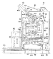
図2は製本装置Bの正面断面図である。 FIG. 2 is a front sectional view of the bookbinding apparatus B.
搬送路13において搬送されるシートS1は、排紙ローラ14、搬送ローラ401を経て一旦反転ガイド402に排出される。反転ガイド402上に排出されたシートS1は整合部材403によって搬送方向とは直交する方向に整合され、ストッパ404の作動によって一時的に集積される。ストッパ404は実線の位置と点線の位置との間で動作可能である。反転ガイド402上に一時的に集積されたシートS1が所定枚数に達するとストッパ404が解除され、シートS1の束が集積部50に落下する。この集積部50は支持板502及び受け板506を有し、シートS1は支持板502及び受け板506によって傾斜状態で支持される。傾斜状態で支持されるシートS1は、押し当て部材504によって浮き上がりが抑えられ、整合板505によって整合される。そして、保持板503が作動してシートS1の束を保持し、シートS1の束を保持した状態で集積部50が軸501を軸として回転して、シートS1の束が傾斜状態から垂直状態になる。
The sheet S <b> 1 conveyed in the
図3はシートS1の束に接着剤を塗布する工程を示す。 FIG. 3 shows a step of applying an adhesive to the bundle of sheets S1.
モータM4によって保持板503がシートS1に向けて移動し、保持板503がシートS1を一定の圧で押圧すると、モータM4の駆動トルクの増大を駆動トルク検知センサ(図示せず)で検知して保持板503の移動が停止する。このような構成によりシートS1の束が支持板502と保持板503により強固に挟持されるのである。保持板503の移動量はエンコーダ509により測定され、RAM等の記憶手段に記憶される。
When the holding
シートS1の束が支持板502と保持板503により挟持された段階で、受け板506が駆動機構(図示せず)により90°回転して、図3(b)に示すように退避する。受け板506が退避した段階では、シートS1の束の下面SAと塗布手段として機能する塗布ローラ62は接触していない(図3(c)参照)。
At the stage where the bundle of sheets S1 is sandwiched between the
次に図3(d)に示すように、接着剤63が収容されている塗布部60が上昇して塗布ローラ62がシートS1の束の背部となる下面SAに接触し、塗布部60がシートS1の束の下面SAに沿って移動することによって、接着剤63がシートS1の束の下面SAに塗布される。
Next, as shown in FIG. 3D, the
尚、上記のようにここでは、接着剤を塗布する塗布手段としてローラを用いて説明するが、本発明の趣旨を阻害しないものであれば、例えばベルトやブラシなどでも代用が可能である。塗布する部材としては、接着剤の塗布性や塗布直前の接着剤を十分に溶融した状態となるように熱伝達しやすい点などから、ムラ無く溶融接着剤をシート端に供給する点で有利なため、ローラが好ましい。 As described above, here, a roller is used as the application means for applying the adhesive, but a belt, a brush, or the like can be used as long as it does not impair the gist of the present invention. As a member to be applied, it is advantageous in that the molten adhesive is supplied to the sheet edge without any unevenness from the viewpoint of easy application of the adhesive or heat transfer so that the adhesive immediately before application is sufficiently melted. Therefore, a roller is preferable.
塗布部60による接着剤63の塗布動作を図4に用いて説明する。
The application | coating operation | movement of the
塗布部60は、接着剤63をシート束へ塗布する塗布ローラ62と、接着剤63と、接着剤63を収容する接着剤収容部64と、固形状の接着剤を溶融させるヒータ(図示せず)を有している。接着剤63は接着剤容器66に固形状態で収容されており、塗布部60において接着剤63の残量が少ないと検知すると可動部材65が動き、固形状態のまま塗布部60に供給される。そして塗布部60内のヒータ(図示せず)に温められ、固形状態の接着剤が塗布部60において溶融する。
The
製本動作の開始段階では、塗布部60は図4(a)のように初期位置である右端位置にある。この右端位置は製本装置Bにおける奥側、つまり図1の紙面奥側である。右端位置には、発光素子68Aと受光素子68Bよりなる位置検知センサ68が設けられている。位置検知センサ68により塗布部60の一部が発光素子68Aと受光素子68Bの間に介在することが検知されると、塗布部60が初期位置に存在すると判断されるのである。製本動作を開始すると、塗布部60は右端位置から左端位置(製本装置Bの前面方向)へ移動する。この移動は、モータM3で駆動されるベルト67の駆動で行われる。塗布部60が左端位置に移動する間は、塗布ローラ62はシートS1の束の下面SAから離れている。そして、塗布部60が左端位置から右端位置に向けて移動する図4(b)の段階で、塗布ローラ62がモータM2の駆動で上昇し、シートS1の束の下面SAに接触して接着剤63が塗布される。塗布ローラ62は図4(a)及び図4(b)の破線に示すような軌跡に沿って移動し、また塗布ローラ62は駆動部として機能するモータM1により回転しながらシート束の下面SAに接着剤を塗布する。
At the start of the bookbinding operation, the
図5は表紙S2の接合工程を示す。 FIG. 5 shows the joining process of the cover sheet S2.
表紙S2は図2に示すように、製本装置Bの下部に設けられた表紙収納部80の給紙トレイ801に収納されており、送り出しローラ802により排出される。排出された表紙S2は、カッター81により表紙としての適切な長さに裁断され、表紙支持手段701上に水平状態で載置される。図5の鎖線で示す表紙支持手段701は押圧部材71、72、押圧部材71、72を駆動するカム73、74等の複数の部材で構成される。なお、カッター81は、シートS1のサイズ情報及びシートS1の束の厚さの情報に基づいた所定長さで表紙S2を裁断する。
As shown in FIG. 2, the cover sheet S <b> 2 is stored in a
図5(a)は接着剤63の塗布が完了した状態を示す。図5(a)の状態では、表紙支持手段701は図2に示すように、シートS1の束の下面から離れた下方の位置で表紙S2を支持している。 FIG. 5A shows a state where the application of the adhesive 63 is completed. In the state of FIG. 5A, the cover sheet support means 701 supports the cover sheet S2 at a lower position away from the lower surface of the bundle of sheets S1, as shown in FIG.
次に表紙支持手段701はベルト79A、79B(図2参照)により駆動されて上昇し、図5(b)に示す状態となり、表紙S2がシートS1の束の下面SA、即ち、接着剤塗布面に接触する。なお、表紙押さえ部材75、76、77は表紙支持手段701と一緒に上昇し、下降する。従って、図5(b)に示すように、表紙支持手段701が上昇した時に表紙押さえ部材75、76、77は表紙S2を上から押さえており、表紙S2を平面状態に保持する。
Next, the cover sheet supporting means 701 is driven and lifted by
表紙支持手段701は図5(b)の位置から更に、数mm上昇する。この数mm上昇した位置が図5(c)に示す位置である。押圧部材71、72は表紙S2を左右から押圧し、背表紙と表表紙の境界及び背表紙と裏表紙との境界に角を付与して、表紙S2をシートS1に密着させ、本が形成される。
The cover sheet support means 701 further rises several mm from the position shown in FIG. The position raised several mm is the position shown in FIG. The
図6は接着剤を収容する接着剤収容部の拡大図である。 FIG. 6 is an enlarged view of the adhesive accommodating portion that accommodates the adhesive.
前述したように接着剤収容部64には固形状態の接着剤が供給され、接着剤63は接着剤収容部内で溶融状態となっている。つまり接着剤63はホットメルト接着剤である。接着剤収容部64には一定量の接着剤63が収容されているため、画像形成システムは連続して複数回の製本動作を行うことが出来る。
As described above, the adhesive containing
接着剤収容部64の上部には塗布ローラ62が設置されており、この塗布ローラ62によってシート束の一辺に接着剤63が塗布される。
An
接着剤収容部64の下部には収容部ヒータ61が設置されており、その収容部ヒータ61の上方には塗布ローラ62の内部に塗布手段ヒータとして機能するローラヒータ621が設置されている。この2つのヒータにより接着剤63を上下から加熱することによってヒータの出力値を抑えながら一定量ある接着剤63を迅速に加熱して適正な溶融状態にすることが出来る。複数のヒータの一つを塗布手段である塗布ローラ62に設置することで、少なくとも塗布ローラ自体を迅速に加熱することができるとともに、少なくとも塗布ローラ近傍の接着剤に十分に熱を付与して、接着剤が溶融した状態を早期に作り出すことができる。また、塗布ローラ自体を加熱できるので、接着剤の塗布過程で接着剤が塗布ローラ上で固まってしまうことなどを防ぐことが可能となり、確実にシート端に接着剤を提供でき、接着面の美しい製本が可能となる。塗布手段用のヒータは、たとえば、塗布ローラの塗布に使用される面に外部から接触するように設置したり、塗布ローラの塗布に使用される面に非接触となるように塗布ローラ近傍に設置したり、又は図6に示すように塗布ローラの内部に設置したりすることができる。
A
収容部ヒータ61には収容部温度センサ611が設置されており、ローラヒータ621には塗布手段温度センサとして機能するローラ温度センサ622が設置されている。収容部ヒータ61の動作は収容部温度センサ611により検知された温度に基づいて制御され、ローラヒータ621の動作はローラ温度センサ622により検知された温度に基づいて制御される。これにより両ヒータは適正な温度で制御可能である。
The
ところで接着剤収容部64内の接着剤63は、製本装置Bの電源がOFFされ2つのヒータもOFFされると温度が低下してしまい、適正な溶融状態とは異なる状態になってしまう。そこで、製本装置の電源がONされたら2つのヒータより接着剤63を迅速に加熱し、製本処理が出来るよう接着剤63を適正な溶融状態にする必要がある。
By the way, the temperature of the adhesive 63 in the adhesive accommodating
接着剤63が適正な溶融状態になったかどうかは接着剤63の温度を検知して判断することが考えられる。そこで接着剤63の温度を検知する接着剤温度センサ631を鉛直方向において収容部ヒータ61とローラヒータ621との中間に設置する。収容部ヒータ61とローラヒータ621の中間にある接着剤の温度が適正な温度に達したのであれば、接着剤収容部内の他の位置にある接着剤も収容部ヒータ61やローラヒータ621により適正な温度に達したと判断できる。従って、収容部ヒータ61とローラヒータ621の中間に接着剤温度センサ631を設置すれば、接着剤全体の溶融状態を適正に判断することが出来るのである。ここでいう「中間」とは、図6で示すように鉛直方向において収容部ヒータ61とローラヒータ621との最短距離をXとすると、このXを3等分した中央に位置するX/3の領域のことをいう。例えば鉛直方向において収容部ヒータ61とローラヒータ621との最短距離が60mmであれば中央に位置する20mmが「中間」に該当する。図6で示すように接着剤温度センサ631は中央に位置するX/3の領域内に設置されている。また図7に示すように収容部ヒータ61の真上にローラヒータ621が設置されていない場合でも、図6と同様に最短距離Xを3等分して中央に位置するX/3の領域内に接着剤温度センサ631を設置する。なお、図7で示すように中央に位置するX/3の領域内に接着剤温度センサ631の一部でも入っていれば良い。
It can be considered that the temperature of the adhesive 63 is detected to determine whether or not the adhesive 63 is in an appropriate molten state. Therefore, an
また、接着剤63が適正な温度に達するまでに塗布ローラ62を回転させて接着剤の塗布動作を開始すると、塗布ローラ62の回転に対して溶融していない接着剤が負荷となり、塗布ローラ62の回転が停止してしまう可能性がある。場合によっては塗布ローラ62を回転させるモータM1等が故障してしまう。そこで接着剤温度センサ631の検知結果にもとづき塗布動作を制御する。この点について図7〜10を用いて説明する。
Further, when the
図8は画像形成システムにおける制御系のブロック図であり、ここでは代表的なものだけ示す。 FIG. 8 is a block diagram of a control system in the image forming system, and only a representative one is shown here.
画像形成装置Aにはパソコン等の端末であるPCと製本装置Bが接続されている。 The image forming apparatus A is connected to a PC, which is a terminal such as a personal computer, and a bookbinding apparatus B.
CPU101は画像形成装置A全体の動作を制御するものであり、ROM(Read Only Memory)102やRAM(Random Access Memory)103等に接続されている。このCPU101は、ROM102に格納されている各種制御プログラムを読み出してRAM103に展開し、各部の動作を制御する。また、CPU101は、RAM103に展開したプログラムに従って各種処理を実行し、その処理結果をRAM103に格納する。そして、RAM103に格納した処理結果を所定の保存先に保存させる。
The
画像読取部A3によって生成された画像データや、画像形成装置Aに接続されたPCから送信される画像データは画像処理部104によって画像処理される。画像形成部A1は、画像処理部104によって画像処理された画像データを受け取り、シート上に画像を形成する。
Image data generated by the image reading unit A3 and image data transmitted from a PC connected to the image forming apparatus A are subjected to image processing by the
製本装置BにおけるCPU201(制御手段、ヒータ制御手段)は製本装置B全体の動作を制御するものであり、画像形成装置Aから送信される信号を基づき所定のタイミングで製本動作を実行する。CPU201はROM202に格納されている各種制御プログラムを読み出してRAM203に展開し、各部の動作を制御する。収納部温度センサ611、ローラ温度センサ622、接着剤温度センサ631で検知した結果はCPU201に送られ、その検知結果をもとにCPU201が収容部ヒータ61及びローラヒータ621の動作を制御する。
A CPU 201 (control means, heater control means) in the bookbinding apparatus B controls the overall operation of the bookbinding apparatus B, and executes a bookbinding operation at a predetermined timing based on a signal transmitted from the image forming apparatus A. The
図9はホットメルト接着剤の特性を示しており、収容部ヒータ61等はこのホットメルト接着剤の特性を考慮してON−OFFの動作が制御される。
FIG. 9 shows the characteristics of the hot melt adhesive, and the ON / OFF operation of the
図9の「状態」の欄で示すように、ホットメルト接着剤は70〜80℃では固体となっており、90℃で半液体となっている。従って70〜90℃の範囲内ではホットメルト接着剤が適正な溶融状態になっていない。 As shown in the “state” column of FIG. 9, the hot melt adhesive is solid at 70 to 80 ° C. and is semi-liquid at 90 ° C. Therefore, the hot melt adhesive is not in an appropriate molten state within the range of 70 to 90 ° C.
図9における「接着強度」はホットメルト接着剤の接着力を示すものである。接着強度の欄における「○」は接着力が十分で良好、「△」は接着力がやや不良、「×」は接着力が不良であることを意味する。本発明者は温度をふって接着剤の接着力を検討したところ、接着剤の温度が150〜200℃の範囲内であれば良好な接着力を有することが分かった。 “Adhesive strength” in FIG. 9 indicates the adhesive strength of the hot melt adhesive. In the column of adhesive strength, “◯” means that the adhesive force is sufficient and good, “Δ” means that the adhesive force is slightly poor, and “x” means that the adhesive force is poor. When this inventor examined the adhesive force of the adhesive agent by changing temperature, it turned out that it has favorable adhesive force if the temperature of an adhesive agent exists in the range of 150-200 degreeC.
図9における「蒸発」はホットメルト接着剤が蒸発するか否かを示すものである。両発の欄における「○」はほとんど蒸発しない、「△」はやや蒸発する、「×」はかなり蒸発することを意味する。本発明者は温度をふって蒸発の有無を検討したところ、接着剤の温度が200℃以下であれば蒸発に関して問題ないことが分かった。 “Evaporation” in FIG. 9 indicates whether or not the hot melt adhesive evaporates. “O” in both columns means that it hardly evaporates, “Δ” means that it evaporates slightly, and “X” means that it evaporates considerably. The inventor examined the presence or absence of evaporation by varying the temperature, and found that there was no problem with evaporation if the temperature of the adhesive was 200 ° C. or lower.
図9における「変色」は接着剤をその温度で10時間放置した場合に変色するか否かを示すものである。変色における「○」は変色なし、「△」は変色がややあり、「×」は変色ありを意味する。本発明者は温度をふって変色の有無を検討したところ、接着剤の温度が180℃以下であれば変色に関して問題ないことが分かった。 “Discoloration” in FIG. 9 indicates whether or not the color changes when the adhesive is left at that temperature for 10 hours. In the discoloration, “◯” indicates no discoloration, “Δ” indicates a slight discoloration, and “x” indicates discoloration. The inventor examined the presence or absence of discoloration by varying the temperature, and found that there was no problem with discoloration if the temperature of the adhesive was 180 ° C. or lower.
製本処理に関しては接着剤の接着強度が重要であるため、接着剤の適正温度(所定温度)は150〜200℃の範囲内にあることが好ましい。接着剤の変色も考慮すると更に150〜180℃の範囲内にあることが好ましい。 Since the adhesive strength of the adhesive is important for the bookbinding process, the appropriate temperature (predetermined temperature) of the adhesive is preferably in the range of 150 to 200 ° C. In consideration of discoloration of the adhesive, it is preferably in the range of 150 to 180 ° C.
図10はウォームアップ時の制御動作に関するフローチャート図である。 FIG. 10 is a flowchart relating to the control operation during warm-up.
まず製本装置の電源がONされると(ステップS1)、接着剤の温度がT3未満かどうか判断される(ステップS2)。T3の温度は図9で検討した結果に基づき例えば160℃である。T3の温度は接着剤温度センサ631により検知され、その検知結果をもとにCPU201がT3未満かどうか判断する。
First, when the bookbinding apparatus is powered on (step S1), it is determined whether or not the temperature of the adhesive is lower than T3 (step S2). The temperature of T3 is, for example, 160 ° C. based on the result examined in FIG. The temperature of T3 is detected by the
接着剤の温度がT3未満である場合は(ステップS2;Yes)、接着剤の温度が低下しており、適正な溶融状態になっていないと判断出来るため塗布ローラ62の回転を禁止する(ステップS3)。これにより塗布ローラ62を回転させるモータM1の故障等を防止出来る。一方、接着剤の温度がT3に達した場合は(ステップS2;No)、接着剤が適正に溶融状態にあると判断して塗布ローラ62の回転を許可する(ステップS4)。
When the temperature of the adhesive is lower than T3 (step S2; Yes), the temperature of the adhesive is lowered, and it can be determined that the molten state is not appropriate. S3). As a result, failure of the motor M1 that rotates the
その後は収容部ヒータの温度をT1で制御する。図9で検討した結果を考慮してT1は150〜200℃の範囲内であることが好ましい。本実施形態ではT1を180℃に設定する。収容部ヒータの温度がT1より低ければ(ステップS5;Yes)収容部ヒータをONし(ステップS6)、収容部ヒータの温度がT1以上であれば(ステップS5;No)収容部ヒータをOFFする(ステップS7)。 Thereafter, the temperature of the housing heater is controlled by T1. In consideration of the results examined in FIG. 9, T1 is preferably in the range of 150 to 200 ° C. In this embodiment, T1 is set to 180 ° C. If the temperature of the housing heater is lower than T1 (step S5; Yes), the housing heater is turned on (step S6). If the temperature of the housing heater is T1 or higher (step S5; No), the housing heater is turned off. (Step S7).
ローラヒータの温度はT2で制御する。図9で検討した結果を考慮してT2は150〜200℃の範囲内であることが好ましい。本実施形態ではT2を160℃に設定する。ローラヒータの温度がT2より低ければ(ステップS8;Yes)ローラヒータをONし(ステップS9)、ローラヒータの温度がT2以上であれば(ステップS8;No)ローラヒータをOFFする(ステップS10)。電源がONされている状態でステップS5〜S10の動作を継続し、接着剤収容部64内の接着剤63の温度を適正な温度に維持する。
The temperature of the roller heater is controlled by T2. In consideration of the results examined in FIG. 9, T2 is preferably in the range of 150 to 200 ° C. In this embodiment, T2 is set to 160 ° C. If the temperature of the roller heater is lower than T2 (step S8; Yes), the roller heater is turned on (step S9). If the temperature of the roller heater is equal to or higher than T2 (step S8; No), the roller heater is turned off (step S10). The operation of steps S5 to S10 is continued in a state where the power is on, and the temperature of the adhesive 63 in the adhesive accommodating
尚、下部の収容部ヒータ61は接着剤の全体温度を効率よく制御するため、収容部ヒータ61の温度は制御したい接着剤温度よりも高めに設定することが好ましく、また可能な限り収容部ヒータ61の熱容量は大きいほうが好ましい。上部のローラヒータ621は塗布部に近いので、ローラヒータ621は実際に塗布したい接着剤温度近辺の温度で制御することが好ましく、また、接着剤温度のオーバーシュート低減のためにローラヒータ621の熱容量は小さいほうが好ましい。したがって下部の収納部ヒータの温度>上部のローラヒータの温度とし、また下部の収納部ヒータの熱量>上部のローラヒータの熱量とすることがよい。
Since the
図10とは別の制御動作に関するフローチャート図を図11に示す。 FIG. 11 shows a flowchart relating to a control operation different from FIG.
図10では塗布ローラの回転を許可・禁止していたが、図11では塗布ローラによる塗布動作を許可・禁止する。 In FIG. 10, the rotation of the coating roller is permitted / prohibited, but in FIG. 11, the coating operation by the coating roller is permitted / prohibited.
接着剤の温度がT3未満である場合は(ステップS12;Yes)、塗布ローラ62による塗布動作を禁止し(ステップS13)、接着剤の温度がT3に達した場合は(ステップS12;No)、塗布ローラ62による塗布動作を許可する(ステップS14)。このように制御することによって接着剤が適正な溶融状態で塗布動作が開始される。
When the temperature of the adhesive is lower than T3 (step S12; Yes), the application operation by the
以上図面で説明したように収容部ヒータ61とローラヒータ621の中間に接着剤温度センサ631を設置することによって、接着剤全体の溶融状態を適正に判断することが出来る。また収容部ヒータ61とローラヒータ621の中間に設置した接着剤温度センサ631の検知結果に基づき、塗布動作の許可・禁止又は塗布ローラ回転の許可・禁止を判断することによって、モータの故障等を防止し、良好に塗布動作を実行出来る。つまり一定量の接着剤を収容する場合であっても接着剤の溶融状態を適正に判断してシート束への接着剤の塗布動作を開始することが出来るのである。
As described above with reference to the drawings, by installing the
なお、本発明は当該実施の形態に限定されるものではなく、本発明の要旨を逸脱しない範囲における変更や追加があっても本発明に含まれる。 In addition, this invention is not limited to the said embodiment, Even if there exists a change and addition in the range which does not deviate from the summary of this invention, it is contained in this invention.
図1で示す画像形成システムは画像形成装置Aと製本装置Bが接続されている態様であるが、例えば画像形成装置Aと製本装置Bが一体的となり、一つの装置の形態となっている画像形成システムであっても同様の効果を有する。 The image forming system shown in FIG. 1 is an aspect in which the image forming apparatus A and the bookbinding apparatus B are connected. For example, the image forming apparatus A and the bookbinding apparatus B are integrated to form an image as one apparatus. Even a forming system has the same effect.
A 画像形成装置
B 製本装置
61 収容部ヒータ
62 塗布ローラ
63 接着剤
64 接着剤収容部
101、201 CPU
611 収容部温度センサ
621 ローラヒータ
622 ローラ温度センサ
631 接着剤温度センサ
A Image forming apparatus
611
Claims (6)
溶融した接着剤を収容する接着剤収容部と、
当該接着剤収容部の下部に設置され、前記接着剤収容部に収容された接着剤を加熱する収容部ヒータと、
当該収容部ヒータの上方に設置され、前記接着剤収容部に収容された接着剤を前記シート束の一端側に塗布する塗布手段と、
当該塗布手段に設置され、前記接着剤収容部に収容された接着剤を加熱する塗布手段ヒータと、
鉛直方向において前記収容部ヒータと前記塗布手段ヒータとの中間に設置され、前記接着剤収容部に収容された接着剤の温度を検知する接着剤温度センサと、
前記接着剤温度センサにより検知した接着剤の温度が所定温度に達していない場合、前記塗布手段による接着剤塗布動作を禁止し、前記接着剤温度センサにより検知した接着剤の温度が所定温度に達した場合、前記塗布手段による接着剤塗布動作を許可するべく前記塗布手段を制御する制御手段と、
前記収容部ヒータの温度を検知する収容部温度センサと、
前記塗布手段ヒータの温度を検知する塗布手段温度センサと、
前記収容部温度センサにより検知された温度に基づいて前記収容部ヒータの動作を制御し前記塗布手段温度センサにより検知された温度に基づいて前記塗布手段ヒータの動作を制御するヒータ制御手段と、
を有することを特徴とする製本装置。 A bookbinding apparatus that stacks a plurality of sheets to generate a sheet bundle, and binds the sheet bundle and a cover sheet with an adhesive,
An adhesive container for containing the molten adhesive;
A housing heater installed at a lower portion of the adhesive housing portion and heating the adhesive housed in the adhesive housing portion;
An application unit that is installed above the storage unit heater and applies the adhesive stored in the adhesive storage unit to one end side of the sheet bundle;
An application means heater that is installed in the application means and heats the adhesive contained in the adhesive accommodating portion;
An adhesive temperature sensor that is installed in the middle between the housing heater and the application means heater in the vertical direction and detects the temperature of the adhesive housed in the adhesive housing portion;
When the temperature of the adhesive detected by the adhesive temperature sensor does not reach the predetermined temperature, the adhesive application operation by the application unit is prohibited, and the temperature of the adhesive detected by the adhesive temperature sensor reaches the predetermined temperature. If so, a control means for controlling the application means to permit the adhesive application operation by the application means,
A container temperature sensor for detecting the temperature of the container heater;
An application means temperature sensor for detecting the temperature of the application means heater;
Heater control means for controlling the operation of the container heater based on the temperature detected by the container temperature sensor and for controlling the operation of the application means heater based on the temperature detected by the application means temperature sensor;
A bookbinding apparatus comprising:
前記塗布ローラは駆動部により回動し、
前記制御手段は、前記接着剤温度センサにより検知した接着剤の温度が所定温度に達していない場合、前記塗布ローラによる接着剤塗布動作又は前記塗布ローラの回転を禁止し、前記接着剤温度センサにより検知した接着剤の温度が所定温度に達した場合、前記塗布ローラによる接着剤塗布動作又は前記塗布ローラの回転を許可するべく前記塗布ローラ又は前記駆動部を制御することを特徴とする請求項1に記載の製本装置。 The application means is an application roller;
The application roller is rotated by a driving unit,
When the temperature of the adhesive detected by the adhesive temperature sensor does not reach a predetermined temperature, the control means prohibits an adhesive application operation by the application roller or rotation of the application roller, and uses the adhesive temperature sensor. 2. The application roller or the drive unit is controlled to permit an adhesive application operation by the application roller or rotation of the application roller when the detected temperature of the adhesive reaches a predetermined temperature. The bookbinding apparatus described in 1.
当該画像形成部により画像形成された複数枚のシートを集積してシート束を生成し、当該シート束と表紙を接着剤により接合させて製本する製本部と、
を有する画像形成システムであって、
溶融した接着剤を収容する接着剤収容部と、
当該接着剤収容部の下部に設置され、前記接着剤収容部に収容された接着剤を加熱する収容部ヒータと、
当該収容部ヒータの上方に設置され、前記接着剤収容部に収容された接着剤を前記シート束の一端側に塗布する塗布手段と、
当該塗布手段に設置され、前記接着剤収容部に収容された接着剤を加熱する塗布手段ヒータと、
鉛直方向において前記収容部ヒータと前記塗布手段ヒータとの中間に設置され、前記接着剤収容部に収容された接着剤の温度を検知する接着剤温度センサと、
前記接着剤温度センサにより検知した接着剤の温度が所定温度に達していない場合、前記塗布手段による接着剤塗布動作を禁止し、前記接着剤温度センサにより検知した接着剤の温度が所定温度に達した場合、前記塗布手段による接着剤塗布動作を許可するべく前記塗布手段を制御する制御手段と、
前記収容部ヒータの温度を検知する収容部温度センサと、
前記塗布手段ヒータの温度を検知する塗布手段温度センサと、
前記収容部温度センサにより検知された温度に基づいて前記収容部ヒータの動作を制御し前記塗布手段温度センサにより検知された温度に基づいて前記塗布手段ヒータの動作を制御するヒータ制御手段と、
を有することを特徴とする画像形成システム。 An image forming unit for forming an image on a sheet;
A bookbinding unit that stacks a plurality of sheets imaged by the image forming unit to generate a sheet bundle, and binds the sheet bundle and a cover with an adhesive;
An image forming system comprising:
An adhesive container for containing the molten adhesive;
A housing heater installed at a lower portion of the adhesive housing portion and heating the adhesive housed in the adhesive housing portion;
An application unit that is installed above the storage unit heater and applies the adhesive stored in the adhesive storage unit to one end side of the sheet bundle;
An application means heater that is installed in the application means and heats the adhesive contained in the adhesive accommodating portion;
An adhesive temperature sensor that is installed in the middle between the housing heater and the application means heater in the vertical direction and detects the temperature of the adhesive housed in the adhesive housing portion;
When the temperature of the adhesive detected by the adhesive temperature sensor does not reach the predetermined temperature, the adhesive application operation by the application unit is prohibited, and the temperature of the adhesive detected by the adhesive temperature sensor reaches the predetermined temperature. If so, a control means for controlling the application means to permit the adhesive application operation by the application means,
A container temperature sensor for detecting the temperature of the container heater;
An application means temperature sensor for detecting the temperature of the application means heater;
Heater control means for controlling the operation of the container heater based on the temperature detected by the container temperature sensor and for controlling the operation of the application means heater based on the temperature detected by the application means temperature sensor;
An image forming system comprising:
前記塗布ローラは駆動部により回動し、
前記制御手段は、前記接着剤温度センサにより検知した接着剤の温度が所定温度に達していない場合、前記塗布ローラによる接着剤塗布動作又は前記塗布ローラの回転を禁止し、前記接着剤温度センサにより検知した接着剤の温度が所定温度に達した場合、前記塗布ローラによる接着剤塗布動作又は前記塗布ローラの回転を許可するべく前記塗布ローラ又は前記駆動部を制御することを特徴とする請求項4に記載の画像形成システム。 The application means is an application roller;
The application roller is rotated by a driving unit,
When the temperature of the adhesive detected by the adhesive temperature sensor does not reach a predetermined temperature, the control means prohibits an adhesive application operation by the application roller or rotation of the application roller, and uses the adhesive temperature sensor. when the temperature of the sensing adhesive has reached a predetermined temperature, claim 4, wherein the controller controls the application roller or the driving unit so as to allow rotation of the adhesive applying operation or the application roller by the application roller The image forming system described in 1.
Priority Applications (1)
| Application Number | Priority Date | Filing Date | Title |
|---|---|---|---|
| JP2006264339A JP4984793B2 (en) | 2006-09-28 | 2006-09-28 | Bookbinding apparatus and image forming system |
Applications Claiming Priority (1)
| Application Number | Priority Date | Filing Date | Title |
|---|---|---|---|
| JP2006264339A JP4984793B2 (en) | 2006-09-28 | 2006-09-28 | Bookbinding apparatus and image forming system |
Publications (2)
| Publication Number | Publication Date |
|---|---|
| JP2008080685A JP2008080685A (en) | 2008-04-10 |
| JP4984793B2 true JP4984793B2 (en) | 2012-07-25 |
Family
ID=39352019
Family Applications (1)
| Application Number | Title | Priority Date | Filing Date |
|---|---|---|---|
| JP2006264339A Active JP4984793B2 (en) | 2006-09-28 | 2006-09-28 | Bookbinding apparatus and image forming system |
Country Status (1)
| Country | Link |
|---|---|
| JP (1) | JP4984793B2 (en) |
Families Citing this family (2)
| Publication number | Priority date | Publication date | Assignee | Title |
|---|---|---|---|---|
| JP5036388B2 (en) * | 2007-04-23 | 2012-09-26 | デュプロ精工株式会社 | Bookbinding equipment |
| JP5504617B2 (en) * | 2008-12-03 | 2014-05-28 | コニカミノルタ株式会社 | Bookbinding apparatus and image forming system |
Family Cites Families (4)
| Publication number | Priority date | Publication date | Assignee | Title |
|---|---|---|---|---|
| JPS5351900Y2 (en) * | 1976-12-06 | 1978-12-12 | ||
| JPS63157276U (en) * | 1987-03-31 | 1988-10-14 | ||
| JP4189311B2 (en) * | 2003-12-19 | 2008-12-03 | デュプロ精工株式会社 | Bookbinding equipment |
| JP4564898B2 (en) * | 2004-07-26 | 2010-10-20 | キヤノン株式会社 | Bookbinding apparatus, control method therefor, image forming apparatus, and control method therefor |
-
2006
- 2006-09-28 JP JP2006264339A patent/JP4984793B2/en active Active
Also Published As
| Publication number | Publication date |
|---|---|
| JP2008080685A (en) | 2008-04-10 |
Similar Documents
| Publication | Publication Date | Title |
|---|---|---|
| JP6233359B2 (en) | Image forming apparatus | |
| JP2005049615A (en) | Image forming apparatus | |
| JP4775215B2 (en) | Bookbinding apparatus and image forming system | |
| EP1793284A2 (en) | Image forming apparatus including heating and cooling devices for fixing a toner image on a recording sheet | |
| JP5798576B2 (en) | Image forming apparatus | |
| JP4857064B2 (en) | Bookbinding equipment | |
| JP4984793B2 (en) | Bookbinding apparatus and image forming system | |
| JP2007003992A (en) | Image forming apparatus | |
| JP2005338999A (en) | Imaging system and control method thereof | |
| JP4706486B2 (en) | Bookbinding apparatus and image forming system | |
| JP4407740B2 (en) | Bookbinding apparatus and image forming system | |
| JP4830826B2 (en) | Bookbinding apparatus and bookbinding system | |
| JP4363461B2 (en) | Bookbinding apparatus and image forming system | |
| JP4535105B2 (en) | Bookbinding apparatus and image forming system | |
| JP2008265257A (en) | Bookbinding device and bookbinding system | |
| JP4901356B2 (en) | Bookbinding apparatus and image forming system | |
| JP2009154429A (en) | Bookbinding device and bookbinding system | |
| JP2009113401A (en) | Glue bookbinding machine and image forming system | |
| JP3919450B2 (en) | Image forming apparatus | |
| JP2005308955A (en) | Fixing device and image forming apparatus | |
| JP4539200B2 (en) | Image forming apparatus and image forming system | |
| JP5569300B2 (en) | Post-processing apparatus and image forming system | |
| JP4967821B2 (en) | Image forming system | |
| JP2007307751A (en) | Bookbinding equipment and image forming system | |
| JP4916181B2 (en) | Image forming apparatus |
Legal Events
| Date | Code | Title | Description |
|---|---|---|---|
| A621 | Written request for application examination |
Free format text: JAPANESE INTERMEDIATE CODE: A621 Effective date: 20081219 |
|
| RD03 | Notification of appointment of power of attorney |
Free format text: JAPANESE INTERMEDIATE CODE: A7423 Effective date: 20110225 |
|
| A977 | Report on retrieval |
Free format text: JAPANESE INTERMEDIATE CODE: A971007 Effective date: 20110523 |
|
| A131 | Notification of reasons for refusal |
Free format text: JAPANESE INTERMEDIATE CODE: A131 Effective date: 20110531 |
|
| A02 | Decision of refusal |
Free format text: JAPANESE INTERMEDIATE CODE: A02 Effective date: 20111129 |
|
| A521 | Written amendment |
Free format text: JAPANESE INTERMEDIATE CODE: A523 Effective date: 20120224 |
|
| A911 | Transfer of reconsideration by examiner before appeal (zenchi) |
Free format text: JAPANESE INTERMEDIATE CODE: A911 Effective date: 20120305 |
|
| TRDD | Decision of grant or rejection written | ||
| A01 | Written decision to grant a patent or to grant a registration (utility model) |
Free format text: JAPANESE INTERMEDIATE CODE: A01 Effective date: 20120403 |
|
| A01 | Written decision to grant a patent or to grant a registration (utility model) |
Free format text: JAPANESE INTERMEDIATE CODE: A01 |
|
| A61 | First payment of annual fees (during grant procedure) |
Free format text: JAPANESE INTERMEDIATE CODE: A61 Effective date: 20120416 |
|
| R150 | Certificate of patent or registration of utility model |
Ref document number: 4984793 Country of ref document: JP Free format text: JAPANESE INTERMEDIATE CODE: R150 Free format text: JAPANESE INTERMEDIATE CODE: R150 |
|
| FPAY | Renewal fee payment (event date is renewal date of database) |
Free format text: PAYMENT UNTIL: 20150511 Year of fee payment: 3 |
|
| FPAY | Renewal fee payment (event date is renewal date of database) |
Free format text: PAYMENT UNTIL: 20150511 Year of fee payment: 3 |
|
| S111 | Request for change of ownership or part of ownership |
Free format text: JAPANESE INTERMEDIATE CODE: R313111 |
|
| R360 | Written notification for declining of transfer of rights |
Free format text: JAPANESE INTERMEDIATE CODE: R360 |
|
| R350 | Written notification of registration of transfer |
Free format text: JAPANESE INTERMEDIATE CODE: R350 |