JP4984442B2 - Optical switch device and optical switch method - Google Patents
Optical switch device and optical switch method Download PDFInfo
- Publication number
- JP4984442B2 JP4984442B2 JP2005182424A JP2005182424A JP4984442B2 JP 4984442 B2 JP4984442 B2 JP 4984442B2 JP 2005182424 A JP2005182424 A JP 2005182424A JP 2005182424 A JP2005182424 A JP 2005182424A JP 4984442 B2 JP4984442 B2 JP 4984442B2
- Authority
- JP
- Japan
- Prior art keywords
- pulse
- level
- optical
- control light
- light pulse
- Prior art date
- Legal status (The legal status is an assumption and is not a legal conclusion. Google has not performed a legal analysis and makes no representation as to the accuracy of the status listed.)
- Expired - Fee Related
Links
- 230000003287 optical effect Effects 0.000 title claims description 393
- 238000000034 method Methods 0.000 title claims description 71
- 230000010287 polarization Effects 0.000 claims description 171
- 230000003321 amplification Effects 0.000 claims description 71
- 238000003199 nucleic acid amplification method Methods 0.000 claims description 71
- 230000005284 excitation Effects 0.000 claims description 50
- 239000013307 optical fiber Substances 0.000 claims description 48
- 238000013459 approach Methods 0.000 claims description 38
- 238000012544 monitoring process Methods 0.000 claims description 20
- 230000001360 synchronised effect Effects 0.000 claims description 13
- 239000000284 extract Substances 0.000 claims description 12
- 239000006185 dispersion Substances 0.000 claims description 4
- 230000009022 nonlinear effect Effects 0.000 claims description 3
- 230000008569 process Effects 0.000 description 47
- 101100382379 Rattus norvegicus Cap1 gene Proteins 0.000 description 30
- 238000012937 correction Methods 0.000 description 25
- 238000006243 chemical reaction Methods 0.000 description 23
- 238000010586 diagram Methods 0.000 description 19
- 239000000835 fiber Substances 0.000 description 19
- 230000005374 Kerr effect Effects 0.000 description 10
- 230000000694 effects Effects 0.000 description 9
- 238000004891 communication Methods 0.000 description 8
- 238000012545 processing Methods 0.000 description 8
- 230000005540 biological transmission Effects 0.000 description 7
- 230000008901 benefit Effects 0.000 description 6
- 230000008859 change Effects 0.000 description 6
- 238000005086 pumping Methods 0.000 description 5
- 230000009471 action Effects 0.000 description 4
- 238000005516 engineering process Methods 0.000 description 4
- 230000010363 phase shift Effects 0.000 description 4
- 230000004044 response Effects 0.000 description 4
- 238000012423 maintenance Methods 0.000 description 3
- 230000002269 spontaneous effect Effects 0.000 description 3
- 238000012935 Averaging Methods 0.000 description 2
- 101150047706 CASP6 gene Proteins 0.000 description 2
- 230000008033 biological extinction Effects 0.000 description 2
- 230000007423 decrease Effects 0.000 description 2
- 239000011521 glass Substances 0.000 description 2
- 230000000644 propagated effect Effects 0.000 description 2
- 230000006798 recombination Effects 0.000 description 2
- 238000005215 recombination Methods 0.000 description 2
- 238000001069 Raman spectroscopy Methods 0.000 description 1
- 101000849522 Saccharomyces cerevisiae (strain ATCC 204508 / S288c) 40S ribosomal protein S13 Proteins 0.000 description 1
- 230000003044 adaptive effect Effects 0.000 description 1
- 230000003466 anti-cipated effect Effects 0.000 description 1
- 230000015556 catabolic process Effects 0.000 description 1
- 238000010276 construction Methods 0.000 description 1
- 238000007796 conventional method Methods 0.000 description 1
- 238000006731 degradation reaction Methods 0.000 description 1
- 230000006866 deterioration Effects 0.000 description 1
- 230000005684 electric field Effects 0.000 description 1
- 230000007613 environmental effect Effects 0.000 description 1
- 238000002474 experimental method Methods 0.000 description 1
- 238000000605 extraction Methods 0.000 description 1
- 238000003780 insertion Methods 0.000 description 1
- 230000037431 insertion Effects 0.000 description 1
- 238000004519 manufacturing process Methods 0.000 description 1
- 238000005259 measurement Methods 0.000 description 1
- 230000010355 oscillation Effects 0.000 description 1
- 230000000704 physical effect Effects 0.000 description 1
- 230000001902 propagating effect Effects 0.000 description 1
- 238000012827 research and development Methods 0.000 description 1
- 238000004088 simulation Methods 0.000 description 1
Images


Classifications
-
- G—PHYSICS
- G02—OPTICS
- G02F—OPTICAL DEVICES OR ARRANGEMENTS FOR THE CONTROL OF LIGHT BY MODIFICATION OF THE OPTICAL PROPERTIES OF THE MEDIA OF THE ELEMENTS INVOLVED THEREIN; NON-LINEAR OPTICS; FREQUENCY-CHANGING OF LIGHT; OPTICAL LOGIC ELEMENTS; OPTICAL ANALOGUE/DIGITAL CONVERTERS
- G02F1/00—Devices or arrangements for the control of the intensity, colour, phase, polarisation or direction of light arriving from an independent light source, e.g. switching, gating or modulating; Non-linear optics
- G02F1/35—Non-linear optics
- G02F1/3515—All-optical modulation, gating, switching, e.g. control of a light beam by another light beam
-
- G—PHYSICS
- G02—OPTICS
- G02F—OPTICAL DEVICES OR ARRANGEMENTS FOR THE CONTROL OF LIGHT BY MODIFICATION OF THE OPTICAL PROPERTIES OF THE MEDIA OF THE ELEMENTS INVOLVED THEREIN; NON-LINEAR OPTICS; FREQUENCY-CHANGING OF LIGHT; OPTICAL LOGIC ELEMENTS; OPTICAL ANALOGUE/DIGITAL CONVERTERS
- G02F1/00—Devices or arrangements for the control of the intensity, colour, phase, polarisation or direction of light arriving from an independent light source, e.g. switching, gating or modulating; Non-linear optics
- G02F1/35—Non-linear optics
- G02F1/39—Non-linear optics for parametric generation or amplification of light, infrared or ultraviolet waves
- G02F1/395—Non-linear optics for parametric generation or amplification of light, infrared or ultraviolet waves in optical waveguides
-
- G—PHYSICS
- G02—OPTICS
- G02F—OPTICAL DEVICES OR ARRANGEMENTS FOR THE CONTROL OF LIGHT BY MODIFICATION OF THE OPTICAL PROPERTIES OF THE MEDIA OF THE ELEMENTS INVOLVED THEREIN; NON-LINEAR OPTICS; FREQUENCY-CHANGING OF LIGHT; OPTICAL LOGIC ELEMENTS; OPTICAL ANALOGUE/DIGITAL CONVERTERS
- G02F1/00—Devices or arrangements for the control of the intensity, colour, phase, polarisation or direction of light arriving from an independent light source, e.g. switching, gating or modulating; Non-linear optics
- G02F1/01—Devices or arrangements for the control of the intensity, colour, phase, polarisation or direction of light arriving from an independent light source, e.g. switching, gating or modulating; Non-linear optics for the control of the intensity, phase, polarisation or colour
- G02F1/0136—Devices or arrangements for the control of the intensity, colour, phase, polarisation or direction of light arriving from an independent light source, e.g. switching, gating or modulating; Non-linear optics for the control of the intensity, phase, polarisation or colour for the control of polarisation, e.g. state of polarisation [SOP] control, polarisation scrambling, TE-TM mode conversion or separation
-
- G—PHYSICS
- G02—OPTICS
- G02F—OPTICAL DEVICES OR ARRANGEMENTS FOR THE CONTROL OF LIGHT BY MODIFICATION OF THE OPTICAL PROPERTIES OF THE MEDIA OF THE ELEMENTS INVOLVED THEREIN; NON-LINEAR OPTICS; FREQUENCY-CHANGING OF LIGHT; OPTICAL LOGIC ELEMENTS; OPTICAL ANALOGUE/DIGITAL CONVERTERS
- G02F1/00—Devices or arrangements for the control of the intensity, colour, phase, polarisation or direction of light arriving from an independent light source, e.g. switching, gating or modulating; Non-linear optics
- G02F1/35—Non-linear optics
- G02F1/39—Non-linear optics for parametric generation or amplification of light, infrared or ultraviolet waves
- G02F1/392—Parametric amplification
Description
本発明は、光スイッチ装置及び光スイッチ方法に関し、特に光信号をスイッチする光スイッチ装置及び光信号をスイッチする光スイッチ方法に関する。 The present invention relates to an optical switch device and an optical switch method, and more particularly to an optical switch device that switches an optical signal and an optical switch method that switches an optical signal.
インターネットの急激な普及や大容量コンテンツの増加に伴って、さらなる高速・大容量で柔軟性のある通信ネットワークが要求されている。このような通信ネットワークの構築のためには、光通信技術は不可欠であり、様々な分野での研究開発が行われている。 With the rapid spread of the Internet and the increase in large-capacity content, there is a demand for a communication network that is even faster, has a larger capacity, and is flexible. Optical communication technology is indispensable for the construction of such a communication network, and research and development are being conducted in various fields.
特に、光信号をON/OFFする光スイッチは、将来のフォトニックネットワークを構築する上での重要な構成要素であり、近年では光ファイバの非線形光学効果(ガラス中に比較的強いパワーの光を伝搬させたときに、光強度に応じてガラスの物性が変化して、光学的な応答が線形性を失う現象)を積極的に用いた超高速の光スイッチ技術が注目されている。 In particular, an optical switch for turning on / off an optical signal is an important component for constructing a future photonic network. In recent years, nonlinear optical effects of optical fibers (relatively strong light in glass is used). Attention has been focused on ultra-high-speed optical switch technology that actively uses the phenomenon that when propagating, the physical properties of glass change according to the light intensity and the optical response loses linearity.
従来の光スイッチとして代表的なものに、MEMS(Micro Electro Mechanical Systems)や導波路型スイッチなどがある。MEMSは、マイクロマシン技術を用いて、ミクロンサイズのミラーやシャッターにより、光路を変えて光をON/OFFするものであり、導波路型は、光導波路に対して熱や電界を与えて熱光学効果や電気光学効果を生じさせて、導波路の屈折率を変化させることにより、光をON/OFFさせるものである。 Typical examples of conventional optical switches include MEMS (Micro Electro Mechanical Systems) and waveguide switches. MEMS uses micromachine technology to change the optical path with micron-sized mirrors and shutters to turn on / off light. The waveguide type applies heat and electric field to the optical waveguide to produce thermo-optic effects. In other words, the light is turned ON / OFF by changing the refractive index of the waveguide by generating an electro-optic effect.
MEMSでは、アライメント(ミラー等の素子を光軸の直線上に整列する操作)の許容誤差によって集光効率が低下したり、導波路型スイッチでは、挿入損失(部品挿入時に生じるレベル損失)や、消光比(透過光強度の最大値と最小値の比率)が高くとれないなどの理由によって、レベル低下や雑音が生じやすいといった欠点があった。 In MEMS, the condensing efficiency decreases due to the tolerance of alignment (operation to align elements such as mirrors on the straight line of the optical axis), and in waveguide type switches, insertion loss (level loss that occurs when components are inserted), For example, the extinction ratio (the ratio between the maximum value and the minimum value of the transmitted light intensity) cannot be increased, resulting in a drawback that the level is easily reduced and noise is likely to occur.
このため、従来の光スイッチでは、信号品質の劣化を伴うものであり、また電子的な信号処理によるスイッチ制御では、高速光スイッチングを行うことは不可能であった。
一方、光の物理的特性を活かして、光ファイバの非線形光学効果を用いる光スイッチは、非線形光学効果の発生効率が高い高非線形ファイバ(HNLF:High Non-Linear Fiber)に対し、信号光と制御光(励起光)を入力して、高非線形ファイバ内で生じる非線形屈折率変化に対して、パラメトリック増幅(parametric amplification)を起こさせて、高速スイッチングを行うものである。
For this reason, the conventional optical switch is accompanied by deterioration of signal quality, and it is impossible to perform high-speed optical switching by switch control by electronic signal processing.
On the other hand, an optical switch that uses the nonlinear optical effect of an optical fiber by taking advantage of the physical characteristics of light is controlled with signal light compared to a high nonlinear fiber (HNLF) with high nonlinear optical effect generation efficiency. Light (pumping light) is input and parametric amplification is caused for nonlinear refractive index change that occurs in a highly nonlinear fiber to perform high-speed switching.
パラメトリック増幅とは、信号光の強度を増幅する非線形光学効果のことであり、従来のEDF(Erbium-Doped Fiber)のような線形増幅媒体を用いずに、信号光と制御光とが高非線形ファイバの中で相互作用することで生じる現象である(パラメトリック増幅またはパラメトリック発振は、簡単には、非線形光学媒質中で、高い周波数ω3によって2つの低周波数ω1、ω2の光を発生する過程と定義される)。 Parametric amplification is a nonlinear optical effect that amplifies the intensity of signal light. Signal light and control light are highly nonlinear fiber without using a linear amplification medium such as conventional EDF (Erbium-Doped Fiber). (Parametric amplification or parametric oscillation is simply defined as a process in which light of two low frequencies ω1 and ω2 is generated by a high frequency ω3 in a nonlinear optical medium. )
高非線形ファイバ内で生じるパラメトリック増幅は、非常に高速で生じる光学的物理現象なので、メカニカルな光路切り替えや、熱/電気光学効果によって媒質の屈折率を変化させる現象などよりも、はるかに応答速度が高速であり、高非線形ファイバに入力した超高速光パルスの中から、入力光と同じ速さで、目的とするパルスを抜き出して超高速スイッチングを行うことができ、それと同時に光信号は増幅されて出力される。 Parametric amplification that occurs in a highly nonlinear fiber is an optical physical phenomenon that occurs at a very high speed, so the response speed is much faster than mechanical optical path switching or the phenomenon of changing the refractive index of a medium by the thermal / electro-optic effect. High-speed, ultra-high-speed switching can be performed by extracting the target pulse from the ultra-high-speed optical pulse input to the highly nonlinear fiber at the same speed as the input light. At the same time, the optical signal is amplified. Is output.
このように、高非線形ファイバを用いた光スイッチは、超高速スイッチ動作に加えて光増幅機能を有するので、スイッチング効率が高く(入力信号光パワーに対する出力信号光パワーの比率が大きく)、極低雑音でS/N劣化が非常に少ない高品質な光スイッチング伝送を行えるといった特徴を有しており、次世代の超高速光信号処理の実現に向けて、大きく期待されている技術である。 As described above, an optical switch using a highly nonlinear fiber has an optical amplification function in addition to an ultrahigh-speed switch operation, so that the switching efficiency is high (the ratio of the output signal light power to the input signal light power is large) and extremely low. It has the feature that it can perform high-quality optical switching transmission with very little S / N degradation due to noise, and is a highly anticipated technology for the realization of next-generation ultrahigh-speed optical signal processing.
パラメトリック増幅を用いた従来技術として、入力信号光偏波に依存しない増幅特性を有する光ファイバのパラメトリック増幅器の技術が提案されている(例えば、特許文献1)。
高非線形ファイバで生じるパラメトリック増幅による光スイッチにおいて、光パルスが時間多重(TDM:Time Division Multiplex)された信号光の中から所望の光パルスを抽出してスイッチ出力する場合には、スイッチング対象の光パルスと同じ位相で、かつ光パルスに対してある角度を持って制御光パルスを高非線形ファイバへ入力する。 In an optical switch based on parametric amplification that occurs in a highly nonlinear fiber, when a desired optical pulse is extracted from signal light that has been subjected to time division multiplexing (TDM) and is output as a switch, A control light pulse is input to the highly nonlinear fiber with the same phase as the pulse and at an angle to the light pulse.
図20はパラメトリック増幅を用いた光スイッチ動作の概要を示す図である。高非線形ファイバFに対して、信号光と制御光パルスが入力する。信号光は、光パルスが時間多重されたTDM光信号であり、ch(チャネル)1〜ch4の繰り返しで構成されているとする。 FIG. 20 is a diagram showing an outline of an optical switch operation using parametric amplification. Signal light and control light pulses are input to the highly nonlinear fiber F. The signal light is a TDM optical signal in which optical pulses are time-multiplexed, and is configured by repetition of ch (channel) 1 to ch4.
このとき、ch1、ch3の光パルスのみを抽出してスイッチ出力させる場合には、ch1とch3の光パルスと同一位相で、かつch1、ch3の光パルスの偏光方向に対して一定の角度から制御光パルスp1、p3を高非線形ファイバFへ入射する。 At this time, when only the ch1 and ch3 optical pulses are extracted and output as a switch, they are controlled from the same phase as the ch1 and ch3 optical pulses and from a certain angle with respect to the polarization direction of the ch1 and ch3 optical pulses. The light pulses p1 and p3 are incident on the highly nonlinear fiber F.
すると、高非線形ファイバF内で生じるパラメトリック増幅によって、制御光パルスp1、p3のパワーがch1、ch3の光パルスへ移行し、ch1、ch3の光パルスのみが増幅されて出力することになる(実際には高非線形ファイバFの出力段で、偏光子やバンドパスフィルタなどを用いて余分な光信号をカットするが詳細はここでは省略)。 Then, by the parametric amplification generated in the highly nonlinear fiber F, the power of the control light pulses p1 and p3 shifts to the ch1 and ch3 optical pulses, and only the ch1 and ch3 optical pulses are amplified and output (actually). In the output stage of the highly nonlinear fiber F, an extra optical signal is cut by using a polarizer, a band pass filter or the like, but details are omitted here.
このように、複数のチャネルが時間多重されている信号光に対し、各チャネルに対応した制御光パルスを生成し、スイッチング対象の光パルスに対して、それぞれの制御光パルスを上記の条件で高非線形ファイバFに入力することで、光スイッチ処理を行うことが可能である。 In this way, a control light pulse corresponding to each channel is generated for signal light in which a plurality of channels are time-multiplexed, and each control light pulse is increased under the above conditions for the optical pulse to be switched. By inputting to the nonlinear fiber F, it is possible to perform optical switch processing.
一方、各チャネルの光パルスは、ネットワーク上に散在する各ノードから送信されて到達したものであり、それらの光パルスが時間多重されて、信号光は生成されたものであるので、実際の信号光は、チャネル毎に光レベルに差が生じていることになる。 On the other hand, the optical pulse of each channel is transmitted and arrived from each node scattered on the network, and these optical pulses are time-multiplexed to generate the signal light. The light has a difference in light level for each channel.
このようなレベルの異なるチャネルからなる信号光に対して、従来では、あらかじめ設定されている一定レベルの制御光パルスを高非線形ファイバFに入力して光スイッチングを行っていた。このため、スイッチング後の光パルスのレベルには、ばらつきが生じることになり、受信側でレベル補償をしなければならないといった問題があった。 Conventionally, optical switching is performed by inputting a predetermined level of a control light pulse to the highly nonlinear fiber F with respect to signal light composed of channels having different levels. For this reason, variations occur in the level of the optical pulse after switching, and there is a problem that level compensation must be performed on the receiving side.
図21は問題点を説明するための図である。信号光は、ch1〜ch4の繰り返しからなるTDM光信号であり、ch1〜ch4のレベルは互いに異なっている。また、ch1〜ch4の光パルスに対応する制御光パルスp1〜p4は、すべて同じ一定レベルである。 FIG. 21 is a diagram for explaining the problem. The signal light is a TDM optical signal composed of repetition of ch1 to ch4, and the levels of ch1 to ch4 are different from each other. The control light pulses p1 to p4 corresponding to the ch1 to ch4 light pulses are all at the same constant level.
従来のように、信号光の各チャネルに対応する制御光パルスのレベルがすべて固定である場合に、制御光パルスp1〜p4を上述の条件で高非線形ファイバFへ入力し、ch1〜ch4の4チャネルを出力させると、出力したch1〜ch4のレベル差の比率は、高非線形ファイバFの入力時のレベル差の比率と同じ状態で出力されることになる。 As in the prior art, when all the levels of the control light pulses corresponding to each channel of the signal light are fixed, the control light pulses p1 to p4 are input to the highly nonlinear fiber F under the above conditions, and 4 of ch1 to ch4. When the channel is output, the level difference ratio of the output ch1 to ch4 is output in the same state as the level difference ratio at the time of input of the highly nonlinear fiber F.
すなわち、スイッチ出力された各チャネルの光パルスのレベルには、ばらつきが生じるため、受信するノード側では、受信ノード毎にレベルを補償しなければならず、システム運用の利便性を低下させるといった問題があった。 That is, since the level of the optical pulse of each channel that is output from the switch varies, there is a problem in that the receiving node must compensate the level for each receiving node, which reduces the convenience of system operation. was there.
また、レベル補償するために、高非線形ファイバFの後段において、光増幅器をチャネル数分設置して、スイッチ出力後のすべてのチャネルのレベルを一定に増幅制御することも考えられる。 Further, in order to compensate the level, it is conceivable that optical amplifiers are installed for the number of channels in the subsequent stage of the highly nonlinear fiber F, and the levels of all the channels after the switch output are controlled to be constant.
しかし、近年では通信トラフィックの急激な増加に伴い、使用すべきチャネル数も増加しており、時間多重されている光パルスのチャネル数も非常に多く、そのような状況において、ネットワーク上の光スイッチングを行うノード毎に、すべてのチャネルに対応してレベル補償するための光増幅器を設置すると、装置規模及びコストが増大してしまい、超高速光通信ネットワークを経済的に構築する上での大きな障害要因となってしまう。 However, in recent years, with the rapid increase in communication traffic, the number of channels to be used has increased, and the number of time-multiplexed optical pulse channels is also very large. If an optical amplifier for level compensation corresponding to all channels is installed in each node, the scale and cost of the apparatus increase, which is a major obstacle to economically constructing an ultrahigh-speed optical communication network. It becomes a factor.
本発明はこのような点に鑑みてなされたものであり、時間多重された光パルスのスイッチ出力レベルを適応的に制御して、高品質で柔軟性のある光スイッチングを行う光スイッチ装置を提供することを目的とする。 The present invention has been made in view of these points, and provides an optical switch device that adaptively controls the switch output level of time-multiplexed optical pulses to perform high-quality and flexible optical switching. The purpose is to do.
また、本発明の他の目的は、時間多重された光パルスのスイッチ出力レベルを適応的に制御して、高品質で柔軟性のある光スイッチングを行う光スイッチ方法を提供することである。 Another object of the present invention is to provide an optical switch method for performing high-quality and flexible optical switching by adaptively controlling the switch output level of time-multiplexed optical pulses.
上記課題を解決するために、光スイッチ装置が提供される。この光スイッチ装置は、複数のチャネルの光パルスが時間多重された第1の波長を有する入力光を入力し、偏光方向を制御した偏光入力光を出力する第1の偏光制御部と、連続した制御光パルスから構成された、前記第1の波長とは異なる第2の波長を有する制御光を生成する制御光生成部と、前記制御光を入力し、偏光方向を制御した偏光制御光を出力する第2の偏光制御部と、前記偏光入力光および前記偏光制御光を入力し、前記偏光制御光の非線形効果によって、前記偏光入力光に対して増幅および偏光回転を生じさせて、増幅光として出力する非線形光ファイバと、前記第1の偏光制御部で制御した偏光方向と直交する偏光軸を有し、前記増幅光が入力する偏光子と、前記偏光子から出力された前記増幅光をモニタするモニタ部と、を備え、前記制御光生成部は、前記モニタ部のモニタ結果にもとづき、連続する前記制御光パルスの各光パワーを制御し、前記第2の偏光制御部は、前記モニタ部のモニタ結果にもとづき、連続する前記制御光パルスの各偏光方向を制御し、前記第2の偏光制御部は、前記偏光入力光に対して所定角度を形成する偏光方向を持った前記偏光制御光を出力し、前記モニタ部は、前記偏光子から出力された前記増幅光のレベルをモニタし、モニタ値と目標値とを比較して、差分値を算出し、前記制御光生成部は、前記差分値がゼロに近づくように励起レベルを可変に設定した前記制御光パルスを生成し、前記第2の偏光制御部は、前記入力光のスイッチ出力対象の光パルスであるスイッチ対象光パルスに対して、前記スイッチ対象光パルスと同一位相の前記制御光パルスに前記所定角度を持たせて、前記非線形光ファイバへ入力することで、前記非線形光ファイバ内で、増幅および偏光回転を生じさせて、スイッチ出力後の光パルスのレベルが所望レベルに設定された光スイッチングを行う。 In order to solve the above problems, an optical switch device is provided. This optical switch device is connected to a first polarization control unit that inputs input light having a first wavelength in which optical pulses of a plurality of channels are time-multiplexed and outputs polarized input light whose polarization direction is controlled. A control light generation unit configured to generate control light having a second wavelength different from the first wavelength, which is composed of control light pulses, and input the control light and output polarization control light in which the polarization direction is controlled A second polarization control unit that inputs the polarization input light and the polarization control light, and causes amplification and polarization rotation with respect to the polarization input light due to a nonlinear effect of the polarization control light, and A nonlinear optical fiber to output, a polarization axis orthogonal to the polarization direction controlled by the first polarization controller, a polarizer to which the amplified light is input, and the amplified light output from the polarizer are monitored A monitor unit to The control light generation unit controls each optical power of the continuous control light pulse based on the monitor result of the monitor unit, and the second polarization control unit is based on the monitor result of the monitor unit, Each polarization direction of the continuous control light pulse is controlled, and the second polarization control unit outputs the polarization control light having a polarization direction that forms a predetermined angle with respect to the polarization input light, and the monitor The unit monitors the level of the amplified light output from the polarizer, compares the monitor value with a target value, calculates a difference value, and the control light generation unit causes the difference value to approach zero. In this way, the control light pulse having the excitation level variably set is generated, and the second polarization control unit generates the switch target light with respect to the switch target light pulse that is the switch output target light pulse of the input light. Same as pulse By giving the control optical pulse of the phase the predetermined angle and inputting it to the nonlinear optical fiber, amplification and polarization rotation are caused in the nonlinear optical fiber, and the level of the optical pulse after the switch output is Optical switching set to a desired level is performed.
非線形光学効果を利用した光スイッチに対して、時間多重された光パルスのスイッチ出力レベルを適応的に制御した光スイッチングを行うことができるので、高品質で柔軟性のある光スイッチングを行うことが可能になる。また、スイッチ出力後の光パルスのレベルが所望レベルに設定された光スイッチングを行うことが可能になる。
To light switch using non-linear optical effect, it is possible to perform the optical switching adapted to control the switch output level of the time multiplexed optical pulses, to perform the optical switching of a flexible high quality Is possible. Further, it is possible to perform optical switching in which the level of the optical pulse after the switch output is set to a desired level.
以下、本発明の実施の形態を図面を参照して説明する。図1は光スイッチ装置の原理図である。光スイッチ装置10は、非線形光ファイバ11、信号光偏光制御部12(第1の偏光制御部に該当)、偏光子13、レベルモニタ部14(モニタ部に該当)、制御光パルス設定部15、フィルタ16、カプラC1、C2から構成され、光パルスをスイッチして伝送する装置である。
Hereinafter, embodiments of the present invention will be described with reference to the drawings. FIG. 1 is a principle diagram of an optical switch device. The optical switch device 10 includes a nonlinear
非線形光ファイバ11は、非線形光学効果を有し、複数のチャネルの光パルスが時間多重された信号光(TDM信号光)が入力する。非線形光ファイバ11の長さは、例えば、20〜30mの実用的な長さである。なお、非線形光ファイバ11は、非線形光学効果の発生効率が高い高非線形ファイバを使用するものとし、以降では、HNLF11と呼ぶ。
The nonlinear
信号光偏光制御部12は、信号光の偏光方向を制御する。偏光子13は、HNLF11の出力段に設けられ、信号光偏光制御部12で制御された信号光の偏光方向と直交する偏光主軸を有する。
The signal light
具体的には、偏光子13は、偏光主軸成分の光のみを通過させる光フィルタの機能を有している。また、信号光偏光制御部12は、偏光子13の偏光主軸と直交するように信号光の偏光方向を設定制御する。
Specifically, the polarizer 13 has a function of an optical filter that allows only light of the polarization main axis component to pass therethrough. Further, the signal light
レベルモニタ部14は、偏光子13を透過し、かつフィルタ16でフィルタリングされたスイッチ出力後の光パルスを、カプラC2を介して受信し、受信した光パルスのレベルをモニタする。そして、モニタ値と目標値とを比較して、差分値を算出する。レベルモニタ部14では、このような差分値や、または各光パルスのモニタ値を制御光パルス設定部15へ送信する。
The
制御光パルス設定部15は、制御光パルス生成部15a(制御光生成部に該当)、制御光パルス偏光制御部15b(第2の偏光制御部に該当)及び制御部15cを含む。制御光パルス生成部15aは、信号光の波長とは異なる波長を有し、差分値がゼロに近づくように、励起レベルを可変に設定した制御光パルスを生成する(信号光の波長λsと制御光パルスの波長λpは互いに異なり、また制御光パルスは、信号光の光パルスと同期して生成される)。
The control light pulse setting unit 15 includes a control light
制御光パルス偏光制御部15bは、制御光パルスの偏光方向を信号光の偏光方向に対して所定角度(約45度)に設定する。
制御部15cは、制御光パルス生成部15a及び制御光パルス偏光制御部15bに対して、制御光パルスのレベル設定の指示や偏光方向の角度設定の指示などの制御光パルス設定に必要な全体制御を行う(装置全体の制御も兼ねている)。
The control light pulse polarization controller 15b sets the polarization direction of the control light pulse to a predetermined angle (about 45 degrees) with respect to the polarization direction of the signal light.
The
また、制御部15cには保守端末(図示せず)が接続可能であり、レベルモニタ部14から送信される各光パルス(チャネル)のモニタ値を、保守端末の画面上に表示するなどして、システムの運用状態や障害チャネルをオペレータが確認することが可能である。さらに、保守端末から制御部15cを介して、レベルモニタ部14へスイッチ出力後の光パルスの目標レベル設定を行うことができる。
A maintenance terminal (not shown) can be connected to the
制御光パルス設定部15では、上述のレベルモニタ部14及び制御光パルス生成部15aによるフィードバック制御によって求められた励起レベルを設定した制御光パルスを生成する(HNLF11内でパラメトリック増幅を生じさせるのに必要なパワーの範囲内で、差分値がゼロに近づくように、制御光パルスの励起レベルを可変に設定する)。
The control light pulse setting unit 15 generates a control light pulse in which the excitation level obtained by the feedback control by the
そして、信号光のスイッチ出力対象の光パルスである、スイッチ対象光パルスに対して、この制御光パルスをスイッチ対象光パルスと同一位相で、かつ所定角度を持たせて、HNLF11へ入力することで、HNLF11内で偏光回転及びパラメトリック増幅を起こさせる。これによって、スイッチ出力後の光パルスのレベルが所望レベルに設定された、パラメトリック増幅による光スイッチングを実行する。
Then, the control light pulse is input to the
なお、偏光回転及びパラメトリック増幅は、信号光全体に生じるものではなく、制御光パルスと時間的に重複する時間領域でのみ生じるものなので、スイッチ対象光パルス以外の光パルスについては、偏光回転及びパラメトリック増幅は生じない。偏光回転及びパラメトリック増幅の詳細については後述する。 Note that the polarization rotation and parametric amplification do not occur in the entire signal light, but only in the time domain that overlaps with the control light pulse in time. No amplification occurs. Details of polarization rotation and parametric amplification will be described later.
フィルタ16は、バンドパスフィルタであり、信号光の波長λsのみを通過させ、他の波長の光をカットする。すなわち、制御光パルス(波長λp)やHNLF11で発生した自然放出光(ASE:Amplified Spontaneous Emission)などの光は、このフィルタ16によってカットされる。
The
なお、制御光パルスの波長が信号光の波長から大きく離れていたり、偏光子13を通過する信号光のパワーが自然放出光と比較して十分に大きい場合などには、フィルタ16は必ずしも設ける必要はない。
Note that the
次に光スイッチ装置10の動作概要について説明する。図2は光スイッチ装置10の動作概要を示す図である。信号光は、ch1〜ch4の光パルスの繰り返しからなるTDM光信号であり、ch1〜ch4のレベルは互いに異なっている。 Next, an outline of the operation of the optical switch device 10 will be described. FIG. 2 is a diagram showing an outline of the operation of the optical switch device 10. The signal light is a TDM optical signal formed by repetition of ch1 to ch4 optical pulses, and the levels of ch1 to ch4 are different from each other.
初期状態では、制御光パルス生成部15aは、各チャネルの光パルスに対して、一定レベル(初期値レベル)の制御光パルスをHNLF11に入力する。そして、レベルモニタ部14は、HNLF11から出力された光パルスのレベルをそれぞれモニタし、目標値との差分を算出し、制御光パルス生成部15aへ送信する。
In the initial state, the control light
そして、運用状態では、制御光パルス生成部15aは、各チャネルの差分値にもとづいて設定した励起レベルを持つ制御光パルスを生成して、HNLF11へ入力することで、スイッチ出力後のレベルのばらつきを抑制する。
In the operation state, the control light
ここで、スイッチ出力後のch1〜ch4のすべてのレベルの目標値をLTとする。光パルスch1に対して、光パルスch1と、初期値レベルを設定した制御光パルスと、を同じタイミングでかつ所定の角度でHNLF11へ入力する。レベルモニタ部14は、HNLF11通過後のパラメトリック増幅された光パルスch1のレベルをモニタし、モニタ値と目標値LTとの差分値を算出する。
Here, the target value for all levels of ch1~ch4 after switch output and L T. For the optical pulse ch1, the optical pulse ch1 and the control optical pulse with the initial value level set are input to the
制御光パルス生成部15aは、差分値がゼロに近づくように、光パルスch1に対応する制御光パルスp1の励起レベルを補正して、スイッチ出力後の光パルスch1のレベルをLTと設定する。
Control
同様に光パルスch2に対して、光パルスch2と、初期値レベルを設定した制御光パルスと、を同じタイミングでかつ所定の角度でHNLF11へ入力する。レベルモニタ部14は、HNLF11通過後のパラメトリック増幅された光パルスch2のレベルをモニタし、モニタ値と目標値LTとの差分値を算出する。
Similarly, with respect to the optical pulse ch2, the optical pulse ch2 and the control optical pulse with the initial value level set are input to the
制御光パルス生成部15aは、差分値がゼロに近づくように、光パルスch2に対応する制御光パルスp2の励起レベルを補正して、スイッチ出力後の光パルスch2のレベルをLTと設定する。他のchのレベル設定も同様である。
Control
このように、光スイッチ装置10では、スイッチ出力レベルを目標値のレベルとなるようにフィードバックして制御光パルスの励起レベルを可変設定し、光スイッチングを行う構成としたので、スイッチ出力レベルのばらつきを抑制することが可能になる。 As described above, since the optical switch device 10 is configured to perform the optical switching by feeding back the switch output level to the target value level and variably setting the excitation level of the control light pulse, the switch output level varies. Can be suppressed.
また、この例では、すべてのスイッチ出力後の光パルスのレベルを同一レベルとなるように制御したが、光スイッチ装置10では、チャネル単位に個別にスイッチ出力レベルを制御することができるので、一方のチャネルの出力レベルは高くし、他方のチャネルの出力レベルは低くするといったように、各チャネルの光パルスを受信する装置の受信状態に応じて所望のレベルに設定することができ(意図的にスイッチ出力レベルにばらつきを持たせることが可能)、スイッチ運用に対して柔軟性を持たせることが可能である。 In this example, the optical pulse levels after all switch outputs are controlled to be the same level. However, in the optical switch device 10, the switch output level can be individually controlled for each channel. The output level of one channel can be set high, and the output level of the other channel can be set low, so that it can be set to a desired level according to the reception state of the optical pulse receiving device of each channel (intentionally The switch output level can be varied), and the switch operation can be flexible.
ここで、制御光パルス生成部15aで、制御光パルスp1〜p4を生成する場合においては、制御光パルスp1〜p4の各波長はすべて同一であり、その波長はHNLF11のゼロ分散波長と一致させるものとする。
Here, in the case where the control light pulses p1 to p4 are generated by the control light
理由としては、HNLF11の平均ゼロ分散波長(特定の波長で波形の広がり(波長分散)が最小になるところ)と制御光パルスの波長とが略一致するように設定すると、非線形光学効果によって生じる新たな光と制御光パルスの位相が整合することになり、後述のパラメトリック増幅の発生効率が高くなるからである。 The reason is that if the average zero dispersion wavelength of the HNLF 11 (where the waveform spread (wavelength dispersion) is minimized at a specific wavelength) and the wavelength of the control light pulse are set to substantially coincide with each other, a new one caused by the nonlinear optical effect is generated This is because the phase of the control light pulse and the control light pulse are matched, and the generation efficiency of the parametric amplification described later is increased.
また、光増幅では波長毎に利得は異なるので、制御光パルスの波長を同一にしておけば、スイッチ出力のレベル制御において、制御光パルス毎の利得も同一化することができ、レベル制御がしやすくなるといった利点もある。 In addition, since the gain differs for each wavelength in optical amplification, if the wavelength of the control light pulse is the same, the gain for each control light pulse can be made the same in the level control of the switch output. There is also an advantage that it becomes easy.
次に光スイッチ装置10で実現される光スイッチ制御について段階的に詳しく説明する。非線形光学媒質で生じる非線形光学効果の現象には大別すると、非線形屈折率変化と非線形散乱とがある。 Next, the optical switch control realized by the optical switch device 10 will be described in detail step by step. Phenomenon of the nonlinear optical effect generated in the nonlinear optical medium is roughly classified into a nonlinear refractive index change and nonlinear scattering.
前者の非線形屈折率変化は、光の強度に応じて媒質の屈折率が変化する現象であり、代表的なものに、自己位相変調(SPM:Self Phase Modulation)、相互位相変調(XPM:Cross Phase Modulation)及び4光波混合(FWM:Four Wave Mixing)がある。 The former nonlinear refractive index change is a phenomenon in which the refractive index of the medium changes according to the intensity of light. Typical examples include self phase modulation (SPM) and cross phase modulation (XPM). Modulation) and four wave mixing (FWM).
SPMは、1波の伝送で位相シフトを生じる現象であり(自分自身の光強度で位相が変化)、XPMは、異なる波長の光が、同時に同一方向に伝送したときに生じる位相シフト現象である(別の光の強度により位相が変化)。また、FWMは、2つ以上の光から新しい光が生成される現象である(ちなみに、非線形散乱には、誘導ラマン散乱や誘導ブリルアン散乱などがあるが、本発明の内容とは直接関係ないので説明は省略する)。 SPM is a phenomenon that causes a phase shift by transmission of one wave (the phase changes depending on its own light intensity), and XPM is a phase shift phenomenon that occurs when light of different wavelengths is simultaneously transmitted in the same direction. (Phase changes due to different light intensity). FWM is a phenomenon in which new light is generated from two or more lights (incidentally, nonlinear scattering includes stimulated Raman scattering and stimulated Brillouin scattering, but is not directly related to the contents of the present invention. (Description is omitted).
非線形屈折率変化は、光カー効果(optical Kerr effect)とも呼ばれる。光スイッチ装置10の光スイッチ制御では、まず、この光カー効果によって(特にXPMの作用によって)入力信号光に偏光回転を生じさせている。 The nonlinear refractive index change is also called an optical Kerr effect. In the optical switch control of the optical switch device 10, first, polarization rotation is caused in the input signal light by this optical Kerr effect (particularly by the action of XPM).
最初に、信号光の偏光回転及び偏光回転によって実現される光スイッチングについて説明する。なお、説明しやすいように、光カー効果によって実現される光スイッチングのモデルとして光カースイッチを想定する。 First, the polarization switching of signal light and the optical switching realized by the polarization rotation will be described. For ease of explanation, an optical Kerr switch is assumed as a model of optical switching realized by the optical Kerr effect.
図3は光カースイッチを示す図である。光カースイッチ20は、非線形光ファイバ21、信号光偏光制御部22、偏光子23、制御光パルス生成部25aから構成される。非線形光ファイバ21には、信号光及び制御光パルスが入力される。なお、光カースイッチ20で用いる制御光パルスは、レベルが低く、励起の機能は持っていない。また、信号光偏光制御部22は、信号光の偏光方向を、偏光子23の偏光主軸と直交するように設定している。
FIG. 3 is a diagram showing an optical car switch. The optical Kerr switch 20 includes a nonlinear
図4は偏光回転の様子を示す図である。制御光パルス生成部25aで制御光パルスを生成せず、制御光パルスのパワーがゼロであれば、非線形光ファイバ21において信号光の偏光方向は回転しない。この場合、非線形光ファイバ21から出力される信号光の偏光方向は、偏光子23の偏光主軸と直交する状態であるので、信号光は偏光子23により完全に遮断される。
FIG. 4 is a diagram showing a state of polarization rotation. If the control light pulse is not generated by the control
一方、制御光パルス生成部25aが制御光パルスを生成して、信号光の光パルスと同一タイミングで非線形光ファイバ21へ入力したとする。このとき、光パルスと制御光パルスとが時間的に重複した状態で(互いに同一位相で)、制御光パルスのパワーをある程度大きくしていくと、図に示すように、非線形光ファイバ21内では、制御光パルスのパワーに応じて、信号光の偏光方向が回転する。このため、信号光の一部の成分が偏光子23を通過するようになる。
On the other hand, it is assumed that the control
この場合、制御光パルスのパワーを調整することで、信号光の位相を非線形光ファイバ21への入力状態に対して90度だけ変化(回転)させると、信号光の偏光方向は、偏光子23の偏光主軸と一致するので、信号光のほぼ100%が偏光子23を通過することになる。すなわち、信号光の偏光方向を90度だけ回転させるのに必要なパワーを持つ制御光パルスを非線形光ファイバ21に入力すれば、信号光を効率よく抽出できる。
In this case, when the phase of the signal light is changed (rotated) by 90 degrees with respect to the input state to the nonlinear
このように、非線形光ファイバ21へ入力する制御光パルスの光強度を変えて、信号光の偏光方向を、偏光子23の偏光主軸に対して0度または90度に変化させれば、非線形光学効果(光カー効果)による高速の光スイッチングが可能である。しかし、この場合、光スイッチングだけが実現しているだけで、信号光の入力パワーよりも大きなパワーの出力光は得ることができない(信号光が単に回転するだけで増幅作用は起きていないから)。
As described above, if the light intensity of the control light pulse input to the nonlinear
次にパラメトリック増幅を含めた光スイッチの動作について説明する。光スイッチ装置10で行う光スイッチ制御は、上記の偏光回転の作用をベースとしながら、制御光パルスを励起光としてHNLF11に供給することにより、パラメトリック増幅をHNLF11内で生じさせて、高いスイッチング効率を実現するものである。
Next, the operation of the optical switch including parametric amplification will be described. The optical switch control performed by the optical switch device 10 is based on the above-described action of polarization rotation, and supplies a control light pulse to the
なお、上記の光カースイッチ20の場合、非線形光ファイバ21に入力する制御光パルスのパワーは小さく(励起光の役目は持たないので)、小さいパワーの範囲内で制御光パルスのレベルを変化させてスイッチングを行う。
In the case of the optical Kerr switch 20 described above, the power of the control light pulse input to the nonlinear
これに対し、パラメトリック増幅を行う光スイッチ装置10の場合は、HNLF11に入力する制御光パルスのパワーは、光カースイッチ20のそれと比べて非常に大きい(励起光の役目を持たせる)。そして、本発明の光スイッチ装置10では、この大きいパワー(パラメトリック増幅を行うに必要な十分なパワー)の範囲内で制御光パルスのレベルを変えている。
On the other hand, in the case of the optical switch device 10 that performs parametric amplification, the power of the control light pulse input to the
次に一般的なパラメトリック増幅の定義について説明する。パラメトリック増幅は、光の波長域で起こるパラメトリック効果によって生じる増幅現象である。ここで、パラメトリック効果とは、非線形光学媒質において角周波数ω1、ω2、・・・の入射光から新しい角周波数ωn、ωn+1、・・・の光を生じる過程のことであり、通常は、ωpの強い光(励起光)を非線形光学媒質に入射した際に、ωp=ω1+ω2+・・・を満たす複数の低周波の光ω1、ω2・・・を発生させる効果をいう。 Next, a general definition of parametric amplification will be described. Parametric amplification is an amplification phenomenon caused by a parametric effect that occurs in the wavelength region of light. Here, the parametric effect is a process of generating light with new angular frequencies ωn, ωn + 1,... From incident light with angular frequencies ω1, ω2,. When strong light (excitation light) is incident on the nonlinear optical medium, it means an effect of generating a plurality of low-frequency lights ω1, ω2,... Satisfying ωp = ω1 + ω2 +.
この現象は光混合の逆過程に相当する。光混合とは、すなわち非線形光学媒質に角周波数ω1、ω2・・・の複数の光が同時に入射したとき、角周波数ωm=ω1±ω2±・・・の光を発生する効果のことである。 This phenomenon corresponds to the reverse process of light mixing. Light mixing is an effect of generating light having angular frequencies ωm = ω1 ± ω2 ±... When a plurality of lights having angular frequencies ω1, ω2,.
例えば、光混合としてよく知られるものには、FWMがある。FWMは、ω1とω2の2波が非線形光学媒質に入射した場合に、3次の非線形分極を介して、あらたなω3とω4の光を発生させる現象である。 For example, FWM is well known as light mixing. FWM is a phenomenon in which, when two waves of ω1 and ω2 are incident on a nonlinear optical medium, light of new ω3 and ω4 is generated through the third-order nonlinear polarization.
パラメトリック増幅は、パラメトリック効果によって、角周波数ωpの励起光からωp=ωs+ωiの2つの光(信号光とアイドラ(idler)光)が発生し、かつこれらの光が位相整合条件を満たしていると(ωp、ωs、ωiの位相が揃っていると)、最初は弱いωsの光であっても、それとωpとの再結合によってωiを生じ、次にωpとωiの再結合によって、ωsを発生する。これを繰り返し結果的にωsの光(またはωiの光)は、ωpのポンプ光によって増幅されることになる。 In the parametric amplification, two lights (signal light and idler light) of ωp = ωs + ωi are generated from the excitation light of the angular frequency ωp by the parametric effect, and these lights satisfy the phase matching condition ( (If ωp, ωs, and ωi are in phase), even if the light is weak ωs at first, ωi is generated by recombination with ωp, and then ωs is generated by recombination of ωp and ωi. . As a result, the light of ωs (or the light of ωi) is amplified by the pump light of ωp.
次に光スイッチ装置10におけるパラメトリック増幅による光スイッチ制御について説明する。光スイッチ装置10では、HNLF11に対して、信号光及び制御光パルスを合波して入力し、HNLF11内で、スイッチ対象の光パルスの偏光方向を回転させると共に、パラメトリック増幅を起こさせて、スイッチ対象の光パルスを増幅させて抽出し、光スイッチングを実現する。
Next, optical switch control by parametric amplification in the optical switch device 10 will be described. In the optical switch device 10, the signal light and the control light pulse are combined and input to the
ここで、パラメトリック増幅は、非線形光学媒質内で相互作用する光波の偏光方向が互いに一致しているときに発生効率が最大になり、それらの偏光方向が互いに直交しているときにはほとんど発生しないことが知られている。 Here, the parametric amplification has the maximum generation efficiency when the polarization directions of the light waves interacting in the nonlinear optical medium coincide with each other, and hardly occurs when the polarization directions are orthogonal to each other. Are known.
一方、図1の制御光パルス偏光制御部15bでは、上述したように、HNLF11の入力端で、信号光の偏光方向に対して、制御光パルスの偏光方向との間の角度が約45度(以下、単に45度と記す)となるように、制御光パルスの偏光方向を設定している。
On the other hand, as described above, in the control light pulse polarization control unit 15b of FIG. 1, the angle between the polarization direction of the signal light and the polarization direction of the control light pulse at the input end of the
このように、信号光の偏光方向と制御光パルスの偏光方向との間の角度が45度に設定されているので、それらの方向が互いに一致しているときと比較すると、一見、パラメトリック増幅の発生効率は低下するように見える。 As described above, the angle between the polarization direction of the signal light and the polarization direction of the control light pulse is set to 45 degrees. Therefore, compared to when the directions coincide with each other, the parametric amplification seems to be apparent. The generation efficiency seems to decrease.
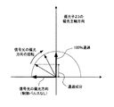
しかし、信号光の偏光方向は、図4で上述したように、光カー効果のXPMの作用により、制御光パルスのパワーに応じて回転するので、信号光の偏光方向の回転量が45度に近づくにつれて、信号光の偏光方向と制御光パルスの偏光方向とが一致する方向に向かい、パラメトリック利得が次第に増大していくことになる(信号光の回転量が45度になれば、信号光及び制御光パルスの偏光方向が一致してパラメトリック利得が最大となる)。 However, as described above with reference to FIG. 4, the polarization direction of the signal light is rotated according to the power of the control light pulse by the action of the optical Kerr effect XPM, so the rotation amount of the polarization direction of the signal light is 45 degrees. As it approaches, the parametric gain gradually increases in the direction in which the polarization direction of the signal light and the polarization direction of the control light pulse coincide with each other (if the amount of rotation of the signal light reaches 45 degrees, The polarization direction of the control light pulse coincides and the parametric gain is maximized).
図5はパラメトリック増幅による光スイッチングの動作を説明するための図である。制御光パルス生成部15aから制御光パルスが出力されないときは、HNLF11において信号光の位相は回転しない。したがって、信号光の偏光方向と偏光子13の偏光主軸は、直交関係となるので、信号光は偏光子13によって完全に遮断される。
FIG. 5 is a diagram for explaining an optical switching operation by parametric amplification. When the control light pulse is not output from the control
一方、制御光パルスがHNLF11に入力すると(信号光の偏光方向と制御光パルスの偏光方向との角度が45度でHNLF11に入力)、図4で上述したように、制御光パルスのパワーに応じて、信号光の偏光方向は回転する。そして、信号光が45度回転したときに、信号光及び制御光パルスの偏光方向が共に一致するので、このときパラメトリック増幅の発生効率が最大となる。 On the other hand, when the control light pulse is input to the HNLF 11 (the angle between the polarization direction of the signal light and the polarization direction of the control light pulse is 45 degrees and input to the HNLF 11), as described above with reference to FIG. Thus, the polarization direction of the signal light rotates. Then, when the signal light rotates 45 degrees, the polarization directions of the signal light and the control light pulse coincide with each other. At this time, the generation efficiency of the parametric amplification is maximized.
ここで、HNLF11内で生じるパラメトリック増幅は、励起光として供給される制御光パルスによって、信号光と同じ波長成分が新たに生成される現象であるが、パラメトリック増幅によって新たに生成される信号光成分は、光カー効果(XPM)の影響を受けることがないので偏光回転を生じない。
Here, the parametric amplification generated in the
すなわち、パラメトリック増幅を発生させることが可能な十分な励起パワーを持つ制御光パルスを45度の角度でHNLF11に入力すると、信号光は45度まで回転し、信号光と制御光パルスの互いの偏光方向が一致して、パラメトリック増幅が最大となる。そして、この時点で、パラメトリック増幅によって増幅された信号光は、光カー効果(XPM)の影響を受けなくなり、信号光は偏光回転しなくなり、この位置で固定するのである。
That is, when a control light pulse having sufficient excitation power capable of generating parametric amplification is input to the
上記の内容をまとめると、光カースイッチ20で使用した制御光パルスは、レベルが低いので、非線形光ファイバにそのような制御光パルスを入力してもパラメトリック増幅は起きず、光カー効果の作用によって、信号光の偏光方向が、制御光パルスのパワーに応じて回転するだけである。 In summary, since the control light pulse used in the optical Kerr switch 20 has a low level, parametric amplification does not occur even when such a control light pulse is input to the nonlinear optical fiber, and the optical Kerr effect is exerted. Thus, the polarization direction of the signal light only rotates according to the power of the control light pulse.
ところが、パラメトリック増幅発生に必要なパワーを持った制御光パルスを例えば、45度でHNLF11に入力すると、パラメトリック増幅発生が最大となる前の状態においては、光カー効果によって信号光は偏光回転するが、偏光回転の過程で制御光パルスの偏光方向と信号光の偏光方向とが一致すると(45度で一致)、そこでパラメトリック増幅が最大となり、そのとき、信号光は光カー効果の影響を受けなくなり、信号光の偏光回転が停止することになる。
However, if a control light pulse having the power necessary for generating parametric amplification is input to the
したがって、パラメトリック増幅が最大となる、信号光と制御光パルスの偏光方向が互いに一致する位置において、信号光は回転しなくなるので、パラメトリック増幅を発生させるパワーの範囲内で(パラメトリック増幅が効率よく生じるパワーの範囲内で)、本発明のように、制御光パルスのパワーを可変に設定しても、信号光は回転せずに45度の位置で固定されるのである。そして、この45度の固定位置で、信号光の増幅量だけが可変されることになる(パラメトリック増幅を発生させるパワーの範囲内で制御光パルスの励起レベルを可変させれば、信号光は45度の位置から動かずに信号増幅量のみが変化するということ)。 Therefore, since the signal light does not rotate at the position where the polarization directions of the signal light and the control light pulse coincide with each other where the parametric amplification is maximized, the parametric amplification is efficiently generated within the range of the power for generating the parametric amplification. Even if the power of the control light pulse is set to be variable as in the present invention (within the power range), the signal light is not rotated but is fixed at a position of 45 degrees. Then, only the amplification amount of the signal light is varied at the fixed position of 45 degrees (if the excitation level of the control light pulse is varied within the power range for generating parametric amplification, the signal light is 45 Only the amount of signal amplification changes without moving from the position of the degree).
一方、図5からわかるように、増幅された信号光は、偏光子13の偏光主軸に対して45度であるので、増幅された信号光の大きさをgとすれば、偏光子13から出力される信号光のパワーは(g/√2)となる。 On the other hand, as can be seen from FIG. 5, since the amplified signal light is 45 degrees with respect to the polarization main axis of the polarizer 13, if the magnitude of the amplified signal light is g, it is output from the polarizer 13. The power of the signal light is (g / √2).
このように、増幅効率は100%ではないものの、元々の入力信号光のパワーと比べれば十分に大きな出力光を得ることができ(パラメトリック増幅により10倍以上の増幅が可能である)、従来の光スイッチに比べて、スイッチング効率を格段に改善することが可能になる。 Thus, although the amplification efficiency is not 100%, a sufficiently large output light can be obtained as compared with the power of the original input signal light (amplification of 10 times or more is possible by parametric amplification). Compared with the optical switch, the switching efficiency can be remarkably improved.
また、パラメトリック増幅を用いた光スイッチ装置10では、制御光パルスをHNLF11に入力しないときのスイッチOFF時においては、信号光の偏光方向は偏光子13の偏光主軸と直交するので信号光は完全に遮断され、制御光パルスを入力したスイッチON時には、パラメトリック増幅によって増幅された信号光(光パルス)が出力するので、非常に良好な消光比及びS/Nを得ることが可能である。
Further, in the optical switch device 10 using parametric amplification, when the control light pulse is not input to the
さらに、光スイッチ装置10では、HNLF11内でXPMやFWMの非線形光学効果によるスイッチングを行うが、これらの非線形光学効果は、いずれもfs(フェムト秒)オーダの応答速度を有する極めて高速な光学現象である。したがって、T(テラ)b/sの光スイッチングを行うことができ、従来の光スイッチと比べてはるかに高速な光スイッチングを実現することが可能である。
Furthermore, the optical switch device 10 performs switching by the nonlinear optical effect of XPM or FWM in the
図6は信号光と制御光パルスの偏光状態の様子を示す図である。パラメトリック増幅による光スイッチング時の信号光と制御光パルスの偏光状態の様子を示している(図5で上述した内容を装置上で示すものである)。 FIG. 6 is a diagram showing the polarization states of the signal light and the control light pulse. The state of the polarization state of the signal light and the control light pulse at the time of optical switching by parametric amplification is shown (the contents described above in FIG. 5 are shown on the apparatus).
信号光の光パルスと、励起レベルを有する制御光パルスは、同一位相タイミングでHNLF11へ入力する。その場合、信号光の偏光方向と制御光パルスの偏光方向とは互いに45度の角度を保ってHNLF11へ入力する。
The optical pulse of the signal light and the control light pulse having the excitation level are input to the
すると、HNLF11内では偏光回転及びパラメトリック増幅が生じて、信号光の偏光方向は、制御光パルスと一致し、かつ信号光のパワーは増幅されて、HNLF11から出力する。また、偏光子13の偏光主軸は垂直方向に切られているので、HNLF11からの出力光の垂直成分が偏光子13を透過して出力する。
Then, polarization rotation and parametric amplification occur in the
次に光スイッチ装置10における、スイッチ出力後の光パルスレベル設定の適応的制御について説明する。なお、以降で示す第1〜第3の実施の形態の動作フローでは、信号光は、ch1〜ch4の4チャネルが時間多重された信号であるとし、制御光パルス設定部15は、各チャネルに応じて制御光パルスp1〜p4を入力信号光に同期して生成する。また、信号光及び制御光パルスそれぞれの偏光方向は45度で、HNLF11に入力されるとする。
Next, adaptive control of optical pulse level setting after switch output in the optical switch device 10 will be described. In the operation flow of the first to third embodiments described below, it is assumed that the signal light is a signal in which four channels ch1 to ch4 are time-multiplexed, and the control light pulse setting unit 15 is provided for each channel. Accordingly, control light pulses p1 to p4 are generated in synchronization with the input signal light. The polarization directions of the signal light and the control light pulse are 45 degrees and are input to the
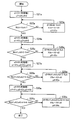
図7は第1の実施の形態の動作フローを示す図である。なお、このフローは、図2で上述した動作内容に対応している。
〔S1〕制御光パルス生成部15aは、制御光パルスp1の初期レベル値をX1と設定して生成する。そして、光パルスch1と制御光パルスp1は、同一タイミングでHNLF11へ入力する。なお、制御光パルスp2〜p4それぞれのレベル値はゼロとする。
FIG. 7 is a diagram showing an operation flow of the first embodiment. This flow corresponds to the operation content described above with reference to FIG.
[S1] The control
〔S2〕レベルモニタ部14は、フィルタ16から出力された光パルスch1を、カプラC2を介して受信し、O/E(光/電気変換)後にレベルをモニタする。モニタ値Mch1が目標値Xch1と等しければステップS4へいき、等しくなければステップS3へいく。
[S2] The
〔S3〕レベルモニタ部14は、モニタ値Mch1と目標値Xch1との差分値d1を算出し、差分値d1を制御光パルス設定部15へ送信する。
〔S4〕制御光パルス生成部15aは、制御光パルスp2の初期レベル値をX2と設定して生成する。そして、光パルスch2と制御光パルスp2は、同一タイミングでHNLF11へ入力する。なお、制御光パルスp1、p3、p4それぞれのレベル値はゼロとする。
[S3] The
[S4] The control
〔S5〕レベルモニタ部14は、フィルタ16から出力された光パルスch2を、カプラC2を介して受信し、O/E変換後にレベルをモニタする。モニタ値が目標値Xch2と等しければステップS7へいき、等しくなければステップS6へいく。
[S5] The
〔S6〕レベルモニタ部14は、モニタ値Mch2と目標値Xch2との差分値d2を算出し、差分値d2を制御光パルス設定部15へ送信する。
〔S7〕制御光パルス生成部15aは、制御光パルスp3の初期レベル値をX3と設定して生成する。そして、光パルスch3と制御光パルスp3は、同一タイミングでHNLF11へ入力する。なお、制御光パルスp1、p2、p4のレベル値はゼロとする。
[S6] The
[S7] The control
〔S8〕レベルモニタ部14は、フィルタ16から出力された光パルスch3を、カプラC2を介して受信し、O/E変換後にレベルをモニタする。モニタ値が目標値Xch3と等しければステップS10へいき、等しくなければステップS9へいく。
[S8] The
〔S9〕レベルモニタ部14は、モニタ値Mch3と目標値Xch3との差分値d3を算出し、差分値d3を制御光パルス設定部15へ送信する。
〔S10〕制御光パルス生成部15aは、制御光パルスp4の初期レベル値をX4と設定して生成する。そして、光パルスch4と制御光パルスp4は、同一タイミングでHNLF11へ入力する。なお、制御光パルスp1、p2、p3のレベル値はゼロとする。
[S9] The
[S10] The control
〔S11〕レベルモニタ部14は、フィルタ16から出力された光パルスch4を、カプラC2を介して受信し、O/E変換後にレベルをモニタする。モニタ値が目標値Xch4と等しければステップS13へいき、等しくなければステップS12へいく。
[S11] The
〔S12〕レベルモニタ部14は、モニタ値Mch4と目標値Xch4との差分値d4を算出し、差分値d4を制御光パルス設定部15へ送信する。
〔S13〕制御光パルス生成部15aは、ステップS3、S6、S9、S12で得られた各差分値d1〜d4がゼロに近づくように、制御光パルスp1〜p4の初期レベル値を補正し、光パルスch1〜ch4のレベルを設定する。
[S12] The
[S13] The control
例えば、ch1に対しては、制御光パルスp1の初期レベル値X1に対して、レベルモニタ部14で算出された差分値d1がゼロとなるように、制御光パルスp1のレベルをX1cと補正して、レベルX1cの制御光パルスをHNLF11へ入力することで、光パルスch1のレベル=Xch1と設定する。
For example, for ch1, the level of the control light pulse p1 is corrected to X1c so that the difference value d1 calculated by the
また、ch2に対しては、制御光パルスp2の初期レベル値X2に対して、レベルモニタ部14で算出された差分値d2がゼロとなるように、制御光パルスp2のレベルをX2cと補正して、レベルX2cの制御光パルスをHNLF11へ入力することで、光パルスch2のレベル=Xch2と設定する。ch3、ch4も同様の制御を行う。
For ch2, the level of the control light pulse p2 is corrected to X2c so that the difference value d2 calculated by the
図8は第1の実施の形態の動作フローを示す図である。
〔S1a〕制御光パルス生成部15aは、制御光パルスp1の初期レベル値をX1と設定して生成する。そして、光パルスch1と制御光パルスp1は、同一タイミングでHNLF11へ入力する。なお、制御光パルスp2〜p4それぞれのレベル値はゼロとする。
FIG. 8 is a diagram showing an operation flow of the first embodiment.
[S1a] The control
〔S2a〕レベルモニタ部14は、フィルタ16から出力された光パルスch1を、カプラC2を介して受信し、O/E(光/電気変換)後にレベルをモニタする。モニタ値Mch1が目標値Xch1と等しければステップS4aへいき、等しくなければステップS3aへいく。
[S2a] The
〔S3a〕レベルモニタ部14は、モニタ値Mch1と目標値Xch1との差分値d1を算出し、差分値d1を制御光パルス設定部15へ送信する。制御光パルス設定部では差分値d1より、差分がゼロとなるような制御光パルスレベルX1cと補正する。補正後ステップS2aへ戻り、目標値となるまで補正を繰り返す。
[S3a] The
〔S4a〕制御光パルス生成部15aは、制御光パルスp2の初期レベル値をX2と設定して生成する。そして、光パルスch2と制御光パルスp2は、同一タイミングでHNLF11へ入力する。なお、制御光パルスp1、p3、p4それぞれのレベル値はゼロとする。
[S4a] The control
〔S5a〕レベルモニタ部14は、フィルタ16から出力された光パルスch2を、カプラC2を介して受信し、O/E変換後にレベルをモニタする。モニタ値が目標値Xch2と等しければステップS7aへいき、等しくなければステップS6aへいく。
[S5a] The
〔S6a〕レベルモニタ部14は、モニタ値Mch2と目標値Xch2との差分値d2を算出し、差分値d2を制御光パルス設定部15へ送信する。制御光パルス設定部では差分値d2より、差分がゼロとなるような制御光パルスレベルX2cと補正する。補正後ステップS5aへ戻り、目標値となるまで補正を繰り返す。
[S6a] The
〔S7a〕制御光パルス生成部15aは、制御光パルスp3の初期レベル値をX3と設定して生成する。そして、光パルスch3と制御光パルスp3は、同一タイミングでHNLF11へ入力する。なお、制御光パルスp1、p2、p4のレベル値はゼロとする。
[S7a] The control
〔S8a〕レベルモニタ部14は、フィルタ16から出力された光パルスch3を、カプラC2を介して受信し、O/E変換後にレベルをモニタする。モニタ値が目標値Xch3と等しければステップS10aへいき、等しくなければステップS9aへいく。
[S8a] The
〔S9a〕レベルモニタ部14は、モニタ値Mch3と目標値Xch3との差分値d3を算出し、差分値d3を制御光パルス設定部15へ送信する。制御光パルス設定部では差分値d3より、差分がゼロとなるような制御光パルスレベルX3cと補正する。補正後ステップS8aへ戻り、目標値となるまで補正を繰り返す。
[S9a] The
〔S10a〕制御光パルス生成部15aは、制御光パルスp4の初期レベル値をX4と設定して生成する。そして、光パルスch4と制御光パルスp4は、同一タイミングでHNLF11へ入力する。なお、制御光パルスp1、p2、p3のレベル値はゼロとする。
[S10a] The control
〔S11a〕レベルモニタ部14は、フィルタ16から出力された光パルスch4を、カプラC2を介して受信し、O/E変換後にレベルをモニタする。モニタ値が目標値Xch4と等しければステップS13aへいき、等しくなければステップS12aへいく。
[S11a] The
〔S12a〕レベルモニタ部14は、モニタ値Mch4と目標値Xch4との差分値d4を算出し、差分値d4を制御光パルス設定部15へ送信する。制御光パルス設定部では差分値d4より、差分がゼロとなるような制御光パルスレベルX4cと補正する。補正後ステップS11aへ戻り、目標値となるまで補正を繰り返す。
[S12a] The
〔S13a〕制御光パルス生成部15aは、ステップS3a、S6a、S9a、S12aで得られた各差分値d1〜d4がゼロに近づくように、制御光パルスp1〜p4の初期レベル値を補正し、光パルスch1〜ch4のレベルを設定する。
[S13a] The control
ここで、図7は、各chのレベル補正値をモニタ値との差分値から一度で設定するため、差分値から補正値への換算精度により、目標値との誤差が決定してしまう欠点があるが、各chでの差分判定は一度のみのため処理速度が速い利点がある。一方、図8では、目標値になるまで補正を繰り返し実行するため、補正値への換算精度は荒くてもよい利点があるが、処理速度が遅い欠点がある。 Here, in FIG. 7, since the level correction value of each channel is set once from the difference value from the monitor value, there is a drawback that an error from the target value is determined by the conversion accuracy from the difference value to the correction value. However, there is an advantage that the processing speed is fast because the difference determination at each channel is performed only once. On the other hand, in FIG. 8, since the correction is repeatedly executed until the target value is reached, there is an advantage that the conversion accuracy to the correction value may be rough, but there is a disadvantage that the processing speed is slow.
次に第2の実施の形態について説明する。図9、図10は第2の実施の形態の動作概要を示す図である。上述の第1の実施の形態では、制御光パルスに対して、レベル設定済みのチャネルの制御光パルスのレベルを落としながら(レベル設定済みのチャネルに対応する制御光パルスのレベルはゼロにしながら)、未設定チャネルの制御光パルスのレベルを設定していくというように、1チャネルずつのレベル設定を行うものなので、すべてのチャネルが設定し終わるまでは、各チャネルは運用状態とはならないが、第2の実施の形態では、レベル設定済みのチャネルを運用状態にしながら、未設定チャネルの制御光パルスのレベルを順次設定していくものである。 Next, a second embodiment will be described. 9 and 10 are diagrams showing an outline of the operation of the second embodiment. In the first embodiment described above, the level of the control light pulse of the channel for which the level has been set is lowered with respect to the control light pulse (while the level of the control light pulse corresponding to the channel for which the level has been set is zero). As the level of the control light pulse of the unconfigured channel is set, the level is set for each channel, so each channel will not be in the operating state until all channels are set. In the second embodiment, the level of the control light pulse of the unset channel is sequentially set while putting the level-set channel in the operating state.
第2の実施の形態は、まず、1つの光パルスチャネル(ch1とする)に対しては、第1の実施の形態と同じような制御を施して、光パルスch1のレベルを目標値Xch1に設定する。 In the second embodiment, first, the same control as in the first embodiment is performed on one optical pulse channel (ch1), and the level of the optical pulse ch1 is set to the target value Xch1. Set.
次に光パルスch2のレベルを設定する場合、レベルモニタ部14は、スイッチ出力信号のレベルモニタとして、光パルスch1、ch2の出力をモニタする。このとき、制御光パルスp1=Xch1(目標値)、制御光パルスp2=X2(初期値)、制御光パルスp3、p4=0である。
Next, when setting the level of the optical pulse ch2, the
ここで、光パルスch2のレベルが目標値Xch2で出力されていれば、出力モニタ値Mch1,ch2は、Mch1,ch2=Xch1+Xch2であり、光パルスch2に対する制御光パルスp2のレベル設定は補正の必要がなく終了である。 If the level of the optical pulse ch2 is output at the target value Xch2, the output monitor values Mch1 and ch2 are Mch1, ch2 = Xch1 + Xch2, and the level setting of the control light pulse p2 with respect to the optical pulse ch2 needs to be corrected. There is no end.
一方、図9のように、Mch1,ch2<Xch1+Xch2の場合には、レベルモニタ部14は、差分値da=(Xch1+Xch2)−Mch1,ch2を算出し、制御光パルス生成部15aは、差分値daがゼロに近づくように、初期レベル値X2を増加補正して制御光パルスp2を生成する。
On the other hand, as shown in FIG. 9, when Mch1, ch2 <Xch1 + Xch2, the
また、図10のように、Mch1,ch2>Xch1+Xch2の場合には、レベルモニタ部14は、差分値db=Mch1,ch2−(Xch1+Xch2)を算出し、制御光パルス生成部15aは、差分値dbがゼロに近づくように、初期レベル値X2を減少補正して制御光パルスp2を出力する。制御光パルスp3、p4の励起レベル設定も同様に行う。
As shown in FIG. 10, when Mch1, ch2> Xch1 + Xch2, the
図9、図10は、信号光ピーク値によるレベル補正方法を図示しているが、信号光の時間平均レベル値によっても同様の方法が実現可能である。
図11は第2の実施の形態の動作フローを示す図である。なお、ここの例では、スイッチ出力後の光パルスp1〜p4は、すべて同じレベルXchに設定するものとする。
9 and 10 illustrate the level correction method based on the signal light peak value, but a similar method can be realized by the time average level value of the signal light.
FIG. 11 is a diagram illustrating an operation flow of the second embodiment. In this example, the optical pulses p1 to p4 after the switch output are all set to the same level Xch.
〔S21〕制御光パルス生成部15aは、制御光パルスp1の初期レベル値をX1と設定し、光パルスch1と同一タイミングで、制御光パルスp1をHNLF11へ入力する。なお、制御光パルスp2〜p4それぞれのレベル値はゼロである。
[S21] The control
〔S22〕レベルモニタ部14は、フィルタ16から出力された光パルスch1を、カプラC2を介して受信し、O/E変換後にレベルをモニタする。モニタ値Mch1が光パルスch1の目標レベル値Xchと等しければステップS25へいき、等しくなければステップS23へいく。
[S22] The
〔S23〕レベルモニタ部14は、モニタ値Mch1と目標値Xchとの差分値d1を算出し、差分値d1を制御光パルス設定部15へ送信する。
〔S24〕制御光パルス生成部15aは、差分値d1がゼロに近づくように、制御光パルスp1のレベルをX1cと補正し、光パルスch1のレベル=Xchと設定する。
[S23] The
[S24] The control
〔S25〕制御光パルス生成部15aは、制御光パルスp2の初期レベル値をX2と設定し、光パルスch2と同一タイミングで、制御光パルスp2をHNLF11へ入力する。なお、制御光パルスp1は、光パルスch1のレベル=Xchとなる補正後のレベルX1cでHNLF11へ入力し、制御光パルスp3、p4それぞれのレベル値はゼロにする。
[S25] The control
〔S26〕レベルモニタ部14は、出力レベルをモニタする。出力モニタ値のMch1,ch2に対して、Mch1,ch2=2・XchであればステップS29へいき、そうでなければステップS27へいく。
[S26] The
〔S27〕レベルモニタ部14は、モニタ値Mch1,ch2と目標値2・Xchとの差分値d2を算出し、差分値d2を制御光パルス設定部15へ送信する。
〔S28〕制御光パルス生成部15aは、差分値d2がゼロに近づくように、制御光パルスp2のレベルをX2cと補正し、光パルスch2のレベル=Xchと設定する。
[S 27] The
[S28] The control
〔S29〕制御光パルス生成部15aは、制御光パルスp3の初期レベル値をX3と設定し、光パルスch3と同一タイミングで、制御光パルスp3をHNLF11へ入力する。なお、制御光パルスp1のレベルは補正後のレベルX1c、制御光パルスp2のレベルは補正後のX2cでHNLF11へ入力し、制御光パルスp4のレベル値はゼロにする。
[S29] The control
〔S30〕レベルモニタ部14は、出力レベルをモニタする。出力モニタ値のMch1,ch2,ch3に対して、Mch1,ch2,ch3=3・XchであればステップS33へいき、そうでなければステップS31へいく。
[S30] The
〔S31〕レベルモニタ部14は、モニタ値Mch1,ch2,ch3と目標値3・Xchとの差分値d3を算出し、差分値d3を制御光パルス設定部15へ送信する。
〔S32〕制御光パルス生成部15aは、差分値d3がゼロに近づくように、制御光パルスp3のレベルをX3cと補正し、光パルスch3のレベル=Xchと設定する。
[S31] The
[S32] The control
〔S33〕制御光パルス生成部15aは、制御光パルスp4の初期レベル値をX4と設定し、光パルスch4と同一タイミングで、制御光パルスp4をHNLF11へ入力する。制御光パルスp1のレベルは補正後のレベルX1c、制御光パルスp2のレベルは補正後のX2c、制御光パルスp3のレベルは補正後のレベルX3cでHNLF11へ入力する。
[S33] The control
〔S34〕レベルモニタ部14は、出力レベルをモニタする。出力モニタ値のMch1,ch2,ch3,ch4に対して、Mch1,ch2,ch3,ch4=4・Xchであれば終了し、そうでなければステップS35へいく。
[S34] The
〔S35〕レベルモニタ部14は、モニタ値Mch1,ch2,ch3,ch4と目標値4・Xchとの差分値d4を算出し、差分値d4を制御光パルス設定部15へ送信する。
〔S36〕制御光パルス生成部15aは、差分値d4がゼロに近づくように、制御光パルスp4のレベルをX4cと補正して、光パルスch4のレベル=Xchと設定する。
[S35] The
[S36] The control
図12は第2の実施の形態の動作フローを示す図である。
〔S21a〕制御光パルス生成部15aは、制御光パルスp1の初期レベル値をX1と設定し、光パルスch1と同一タイミングで、制御光パルスp1をHNLF11へ入力する。なお、制御光パルスp2〜p4それぞれのレベル値はゼロである。
FIG. 12 is a diagram illustrating an operation flow of the second embodiment.
[S21a] The control
〔S22a〕レベルモニタ部14は、フィルタ16から出力された光パルスch1を、カプラC2を介して受信し、O/E変換後にレベルをモニタする。モニタ値Mch1が光パルスch1の目標レベル値Xchと等しければステップS24aへいき、等しくなければステップS23aへいく。
[S22a] The
〔S23a〕レベルモニタ部14は、モニタ値Mch1と目標値Xchとの差分値d1を算出し、差分値d1を制御光パルス設定部15へ送信する。制御光パルス設定部では差分値d1より、差分がゼロとなるような制御光パルスレベルX1cと補正する。補正後ステップS22aへ戻り、目標値となるまで補正を繰り返す。
[S23a] The
〔S24a〕制御光パルス生成部15aは、制御光パルスp2の初期レベル値をX2と設定し、光パルスch2と同一タイミングで、制御光パルスp2をHNLF11へ入力する。なお、制御光パルスp1は、光パルスch1のレベル=Xchとなる補正後のレベルX1cでHNLF11へ入力し、制御光パルスp3、p4それぞれのレベル値はゼロにする。
[S24a] The control
〔S25a〕レベルモニタ部14は、出力レベルをモニタする。出力モニタ値のMch1,ch2に対して、Mch1,ch2=2・XchであればステップS27aへいき、そうでなければステップS26aへいく。
[S25a] The
〔S26a〕レベルモニタ部14は、モニタ値Mch1,ch2と目標値2・Xchとの差分値d2を算出し、差分値d2を制御光パルス設定部15へ送信する。制御光パルス設定部では差分値d2より、差分がゼロとなるような制御光パルスレベルX2cと補正する。補正後ステップS25aへ戻り、目標値となるまで補正を繰り返す。
[S26a] The
〔S27a〕制御光パルス生成部15aは、制御光パルスp3の初期レベル値をX3と設定し、光パルスch3と同一タイミングで、制御光パルスp3をHNLF11へ入力する。なお、制御光パルスp1のレベルは補正後のレベルX1c、制御光パルスp2のレベルは補正後のX2cでHNLF11へ入力し、制御光パルスp4のレベル値はゼロにする。
[S27a] The control
〔S28a〕レベルモニタ部14は、出力レベルをモニタする。出力モニタ値のMch1,ch2,ch3に対して、Mch1,ch2,ch3=3・XchであればステップS30aへいき、そうでなければステップS29aへいく。
[S28a] The
〔S29a〕レベルモニタ部14は、モニタ値Mch1,ch2,ch3と目標値3・Xchとの差分値d3を算出し、差分値d3を制御光パルス設定部15へ送信する。制御光パルス設定部では差分値d3より、差分がゼロとなるような制御光パルスレベルX3cと補正する。補正後ステップS28aへ戻り、目標値となるまで補正を繰り返す。
[S29a] The
〔S30a〕制御光パルス生成部15aは、制御光パルスp4の初期レベル値をX4と設定し、光パルスch4と同一タイミングで、制御光パルスp4をHNLF11へ入力する。制御光パルスp1のレベルは補正後のレベルX1c、制御光パルスp2のレベルは補正後のX2c、制御光パルスp3のレベルは補正後のレベルX3cでHNLF11へ入力する。
[S30a] The control
〔S31a〕レベルモニタ部14は、出力レベルをモニタする。出力モニタ値のMch1,ch2,ch3,ch4に対して、Mch1,ch2,ch3,ch4=4・Xchであれば終了し、そうでなければステップS32aへいく。
[S31a] The
〔S32a〕レベルモニタ部14は、モニタ値Mch1,ch2,ch3,ch4と目標値4・Xchとの差分値d4を算出し、差分値d4を制御光パルス設定部15へ送信する。制御光パルス設定部15では差分値d4より、差分がゼロとなるような制御光パルスレベルX4cと補正する。補正後ステップS31aへ戻り、目標値となるまで補正を繰り返す。
[S32a] The
ここで、図11は、各chのレベル補正値をモニタ値との差分値から一度で設定するため、差分値から補正値への換算精度により、目標値との誤差が決定してしまう欠点があるが、各chでの差分判定は一度のみのため処理速度が速い利点がある。一方、図12では、目標値になるまで補正を繰り返し実行するため、補正値への換算精度は荒くてもよい利点があるが、処理速度が遅い欠点がある。 Here, in FIG. 11, since the level correction value of each channel is set once from the difference value from the monitor value, there is a drawback that an error from the target value is determined by the conversion accuracy from the difference value to the correction value. However, there is an advantage that the processing speed is fast because the difference determination at each channel is performed only once. On the other hand, in FIG. 12, since the correction is repeatedly performed until the target value is reached, there is an advantage that the conversion accuracy to the correction value may be rough, but there is a disadvantage that the processing speed is slow.
なお、上述の第1、第2の実施の形態では、特に運用起動時に存在する信号経路損失等の初期レベル偏差を吸収することに対して有効といえる。
次に第3の実施の形態について説明する。第3の実施の形態では、制御光パルスに低周波信号を重畳して強度変調(振幅変調)を行い、強度変調された制御光パルスをHNLF11へ入力する。そして、スイッチ出力後の強度変調された光パルスに重畳されている低周波信号の振幅にもとづいて、制御光パルスの励起レベルをフィードバック制御し、スイッチ出力後の光パルスのレベルを所望レベルに設定する。
In the first and second embodiments described above, it can be said that it is particularly effective for absorbing an initial level deviation such as a signal path loss existing at the time of starting operation.
Next, a third embodiment will be described. In the third embodiment, intensity modulation (amplitude modulation) is performed by superimposing a low-frequency signal on the control light pulse, and the intensity-modulated control light pulse is input to the
図13は第3の実施の形態の概要を示す図である。
〔S41〕制御光パルスp1に対して、低周波信号を重畳して、低周波重畳信号p1aを生成する。このときの低周波信号は、信号光の周波数よりも十分低域な周波数であり、例えば、信号光が10Gb/s以上ならば、低周波信号は1kHz程度と小さくする。また、制御光パルスp1aの振幅をA1、低周波信号の振幅をA2としたときの変調度(搬送波の振幅と信号波の振幅の比率)mは、m=A2/A1であり、変調度mの強度変調を行うことになる。
FIG. 13 is a diagram showing an outline of the third embodiment.
[S41] A low frequency signal is superimposed on the control light pulse p1 to generate a low frequency superimposed signal p1a. The low frequency signal at this time is a frequency sufficiently lower than the frequency of the signal light. For example, if the signal light is 10 Gb / s or more, the low frequency signal is reduced to about 1 kHz. The modulation degree (ratio of carrier wave amplitude to signal wave amplitude) m when the amplitude of the control light pulse p1a is A1 and the amplitude of the low-frequency signal is A2 is m = A2 / A1, and the modulation degree m Intensity modulation is performed.
〔S42〕スイッチ出力後の信号光は、強度変調が施されて出力される。
〔S43〕レベルモニタ部14は、スイッチ出力後の信号光をO/E変換した後に低周波信号を抽出し、抽出した低周波信号の振幅をモニタする。
[S42] The signal light after the switch output is subjected to intensity modulation and output.
[S43] The
〔S44〕制御光パルス生成部15aは、抽出した低周波信号の振幅が目標値となるように、変調度は一定のまま、制御光パルスレベルを補正する。
図14、図15は第3の実施の形態の動作フローを示す図である。なお、スイッチ出力後の光パルスp1〜p4の目標レベルをXch1〜Xch4とする。
[S44] The control
14 and 15 are diagrams showing an operation flow of the third embodiment. Note that the target levels of the optical pulses p1 to p4 after the switch output are Xch1 to Xch4.
〔S51〕制御光パルス生成部15aは、制御光パルスp1〜p4の初期レベル値をX1〜X4と設定する。
〔S52〕制御光パルス生成部15aは、振幅X1の制御光パルスp1に対して、固定振幅の低周波信号を重畳して、変調度m1の強度変調を行って、光パルスch1と同一タイミングで、制御光パルスp1をHNLF11へ入力する。
[S51] The control
[S52] The control
〔S53〕レベルモニタ部14は、フィルタ16から出力された光パルスch1を、カプラC2を介して受信し、O/E変換後に低周波信号を抽出し、抽出した低周波信号の振幅をモニタする。
[S53] The
〔S54〕レベルモニタ部14は、抽出した低周波信号の振幅と、目標振幅との差分を算出し、差分値d1を制御光パルス設定部15へ送信する。
〔S55〕制御光パルス生成部15aは、差分値d1がゼロに近づくように、変調度m1のまま、制御光パルスp1のレベルを可変設定して補正し、光パルスch1のレベル=Xch1と設定する。
[S54] The
[S55] The control
〔S56〕制御光パルス生成部15aは、振幅X2の制御光パルスp2に対して、固定振幅の低周波信号を重畳して、変調度m2の強度変調を行って、光パルスch2と同一タイミングで、制御光パルスp2をHNLF11へ入力する。
[S56] The control
〔S57〕レベルモニタ部14は、フィルタ16から出力された光パルスch2を、カプラC2を介して受信し、O/E変換後に低周波信号を抽出し、抽出した低周波信号の振幅をモニタする。
[S57] The
〔S58〕レベルモニタ部14は、抽出した低周波信号の振幅と、目標振幅との差分を算出し、差分値d2を制御光パルス設定部15へ送信する。
〔S59〕制御光パルス生成部15aは、差分値d2がゼロに近づくように、変調度m2のまま、制御光パルスp2のレベルを可変設定して補正し、光パルスch2のレベル=Xch2と設定する。
[S58] The
[S59] The control
〔S60〕制御光パルス生成部15aは、振幅X3の制御光パルスp3に対して、固定振幅の低周波信号を重畳して、変調度m3の強度変調を行って、光パルスch3と同一タイミングで、制御光パルスp3をHNLF11へ入力する。
[S60] The control
〔S61〕レベルモニタ部14は、フィルタ16から出力された光パルスch3を、カプラC2を介して受信し、O/E変換後に低周波信号を抽出し、抽出した低周波信号の振幅をモニタする。
[S61] The
〔S62〕レベルモニタ部14は、抽出した低周波信号の振幅と、目標振幅との差分を算出し、差分値d3を制御光パルス設定部15へ送信する。
〔S63〕制御光パルス生成部15aは、差分値d3がゼロに近づくように、変調度m3のまま、制御光パルスp3のレベルを可変設定して補正し、光パルスch3のレベル=Xch3と設定する。
[S62] The
[S63] The control
〔S64〕制御光パルス生成部15aは、振幅X4の制御光パルスp4に対して、固定振幅の低周波信号を重畳して、変調度m4の強度変調を行って、光パルスch4と同一タイミングで、制御光パルスp4をHNLF11へ入力する。
[S64] The control
〔S65〕レベルモニタ部14は、フィルタ16から出力された光パルスch4を、カプラC2を介して受信し、O/E変換後に低周波信号を抽出し、抽出した低周波信号の振幅をモニタする。
[S65] The
〔S66〕レベルモニタ部14は、抽出した低周波信号の振幅と、目標振幅との差分を算出し、差分値d4を制御光パルス設定部15へ送信する。
〔S67〕制御光パルス生成部15aは、差分値d4がゼロに近づくように、変調度m4のまま、制御光パルスp4のレベルを設定して補正し、光パルスch4のレベル=Xch4と設定する。
[S66] The
[S67] The control
図16、図17は第3の実施の形態の動作フローを示す図である。
〔S51a〕制御光パルス生成部15aは、制御光パルスp1〜p4の初期レベル値をX1〜X4と設定する。
16 and 17 are diagrams showing an operation flow of the third embodiment.
[S51a] The control
〔S52a〕制御光パルス生成部15aは、振幅X1の制御光パルスp1に対して、固定振幅の低周波信号を重畳して、変調度m1の強度変調を行って、光パルスch1と同一タイミングで、制御光パルスp1をHNLF11へ入力する。
[S52a] The control
〔S53a〕レベルモニタ部14は、フィルタ16から出力された光パルスch1を、カプラC2を介して受信し、O/E変換後に低周波信号を抽出し、抽出した低周波信号の振幅をモニタする。
[S53a] The
〔S53a−1〕モニタした振幅と目標振幅を比較し、目標振幅と等しければステップS56aへいき、等しくなければステップS54aへいく。
〔S54a〕レベルモニタ部14は、抽出した低周波信号の振幅と、目標振幅との差分を算出し、差分値d1を制御光パルス設定部15へ送信する。
[S53a-1] The monitored amplitude is compared with the target amplitude, and if it is equal to the target amplitude, the process proceeds to step S56a, and if not equal, the process proceeds to step S54a.
[S54a] The
〔S55a〕制御光パルス生成部15aは、差分値d1がゼロに近づくように、変調度m1のまま、制御光パルスp1のレベルを可変設定して補正し、光パルスch1のレベル=Xch1と設定し、ステップS53a−1へいく。
[S55a] The control
〔S56a〕制御光パルス生成部15aは、振幅X2の制御光パルスp2に対して、固定振幅の低周波信号を重畳して、変調度m2の強度変調を行って、光パルスch2と同一タイミングで、制御光パルスp2をHNLF11へ入力する。
[S56a] The control
〔S57a〕レベルモニタ部14は、フィルタ16から出力された光パルスch2を、カプラC2を介して受信し、O/E変換後に低周波信号を抽出し、抽出した低周波信号の振幅をモニタする。
[S57a] The
〔S57a−1〕モニタした振幅と目標振幅を比較し、目標振幅と等しければステップS60aへいき、等しくなければステップS58aへいく。
〔S58a〕レベルモニタ部14は、抽出した低周波信号の振幅と、目標振幅との差分を算出し、差分値d2を制御光パルス設定部15へ送信する。
[S57a-1] The monitored amplitude is compared with the target amplitude, and if equal to the target amplitude, the process proceeds to step S60a, and if not equal, the process proceeds to step S58a.
[S58a] The
〔S59a〕制御光パルス生成部15aは、差分値d2がゼロに近づくように、変調度m2のまま、制御光パルスp2のレベルを可変設定して補正し、光パルスch2のレベル=Xch2と設定し、ステップS57a−1へいく。
[S59a] The control
〔S60a〕制御光パルス生成部15aは、振幅X3の制御光パルスp3に対して、固定振幅の低周波信号を重畳して、変調度m3の強度変調を行って、光パルスch3と同一タイミングで、制御光パルスp3をHNLF11へ入力する。
[S60a] The control light
〔S61a〕レベルモニタ部14は、フィルタ16から出力された光パルスch3を、カプラC2を介して受信し、O/E変換後に低周波信号を抽出し、抽出した低周波信号の振幅をモニタする。
[S61a] The
〔S61a−1〕モニタした振幅と目標振幅を比較し、目標振幅と等しければステップS64aへいき、等しくなければステップS62aへいく。
〔S62a〕レベルモニタ部14は、抽出した低周波信号の振幅と、目標振幅との差分を算出し、差分値d3を制御光パルス設定部15へ送信する。
[S61a-1] The monitored amplitude and the target amplitude are compared. If they are equal to the target amplitude, the process proceeds to step S64a, and if not equal, the process proceeds to step S62a.
[S62a] The
〔S63a〕制御光パルス生成部15aは、差分値d3がゼロに近づくように、変調度m3のまま、制御光パルスp3のレベルを可変設定して補正し、光パルスch3のレベル=Xch3と設定し、ステップS61a−1へいく。
[S63a] The control
〔S64a〕制御光パルス生成部15aは、振幅X4の制御光パルスp4に対して、固定振幅の低周波信号を重畳して、変調度m4の強度変調を行って、光パルスch4と同一タイミングで、制御光パルスp4をHNLF11へ入力する。
[S64a] The control light
〔S65a〕レベルモニタ部14は、フィルタ16から出力された光パルスch4を、カプラC2を介して受信し、O/E変換後に低周波信号を抽出し、抽出した低周波信号の振幅をモニタする。
[S65a] The
〔S65a−1〕モニタした振幅と目標振幅を比較し、目標振幅と等しくなければステップS66aへいく。
〔S66a〕レベルモニタ部14は、抽出した低周波信号の振幅と、目標振幅との差分を算出し、差分値d4を制御光パルス設定部15へ送信する。
[S65a-1] The monitored amplitude is compared with the target amplitude, and if not equal to the target amplitude, the process proceeds to step S66a.
[S66a] The
〔S67a〕制御光パルス生成部15aは、差分値d4がゼロに近づくように、変調度m4のまま、制御光パルスp4のレベルを設定して補正し、光パルスch4のレベル=Xch4と設定し、ステップS65a−1へいく。
[S67a] The control
なお、第3の実施の形態では、特に、運用起動時の信号経路損失等の初期レベル偏差を吸収する場合だけではなく、信号が有効となった後の運用中に生じる環境変化による信号損失偏差や一部の信号の経路が切り替った場合等のレベル偏差の吸収も効果的に行うことができる。 In the third embodiment, in particular, not only the case of absorbing initial level deviations such as signal path loss at the start of operation, but also signal loss deviations due to environmental changes that occur during operation after the signal becomes valid. In addition, it is possible to effectively absorb the level deviation when the path of some signals is switched.
また、上記では、重畳低周波数を1つにして、すべてのchに対する制御光パルスのレベルを補正したが、ch毎に重畳低周波を割り当てて、光出力モニタから各周波数成分を抽出することにより、各ch単位で制御光パルスのレベル補正を行ってもよい。 In the above description, the level of the control light pulse for all the channels is corrected by setting one superimposed low frequency. However, by assigning the superimposed low frequency for each channel and extracting each frequency component from the optical output monitor. The level of the control light pulse may be corrected for each channel.
ここで、第1〜第3の実施の形態において、レベルモニタ部14は、スイッチ出力後の高速光パルス単体のレベルをモニタするのではなく、スイッチ出力の全信号のトータルレベルをモニタしている。
Here, in the first to third embodiments, the
例えば、第1の実施の形態では、ch1のレベルをモニタする際は、ch2〜ch4はOFFとなっているので、スイッチ出力信号はch1のみであり、このときのスイッチ出力信号のトータルレベルをモニタすることで、実質的にch1のレベルを認識している(第2、第3の実施の形態も同様にトータルレベルのモニタを行っている)。 For example, in the first embodiment, when the level of ch1 is monitored, since ch2 to ch4 are OFF, the switch output signal is only ch1, and the total level of the switch output signal at this time is monitored. Thus, the level of ch1 is substantially recognized (the second and third embodiments also monitor the total level in the same manner).
したがって、レベルモニタ部14では、スイッチ出力の全信号の時間平均された値を見ればよいので、通常のPD(Photo Diode)を用いてのモニタ監視が可能であり(もし、高速パルス単体をPDでモニタしようとしても、PDでは、回路内部の時定数によって応答特性が決まるので、高速光パルスに追従できず、明確なパルス強度は認識できない)、信号のビットレート(例えば40Gbit/s)に対し、十分低い帯域(例えば10kHz程度)でのレベル監視が可能である。
Therefore, since the
次に第4の実施の形態について説明する。第1〜第3の実施の形態では、レベルモニタ部14において、スイッチ出力の光パルスのレベルをモニタし、制御光パルス生成部15aで、モニタ結果にもとづいて、制御光パルスのレベルを可変に設定するフィードバック制御としたが、第4の実施の形態では、制御光パルス偏光制御部15bにおいて、信号光の偏光方向に対する制御光パルスの偏光方向の角度を可変に変えて、スイッチ出力後の光パルスのレベルを補正するものである。
Next, a fourth embodiment will be described. In the first to third embodiments, the
すなわち、第1〜第3の実施の形態では、信号光の偏光方向と制御光パルスの偏光方向は常に45度を保ったままで、制御光パルスの励起レベルのみを可変設定したが、第4の実施の形態では、制御光パルスの励起レベルの可変設定に加えて、信号光の偏光方向と制御光パルスの偏光方向との角度の可変設定も行うことにする。 That is, in the first to third embodiments, the polarization direction of the signal light and the polarization direction of the control light pulse are always maintained at 45 degrees, and only the excitation level of the control light pulse is variably set. In the embodiment, in addition to the variable setting of the excitation level of the control light pulse, the variable setting of the angle between the polarization direction of the signal light and the polarization direction of the control light pulse is also performed.
上述の図5からわかるように、スイッチ出力光は、HNLF11内でパラメトリック増幅された信号光の垂直成分のみが、偏光子13から透過されるものなので、制御光パルスの偏光方向の角度を変えることで、スイッチ出力のレベルも可変させることができる。
As can be seen from FIG. 5 described above, the switch output light is such that only the vertical component of the signal light parametrically amplified in the
ただし、信号光の偏光方向と制御光パルスの偏光方向との間の角度は、実験及びシミュレーションにより、HNLF11の入力端において40〜50度が好適であることが認識され、この角度が大きすぎると、信号光の偏光回転が起こりにくくなり、小さすぎると偏光子13による損失が大きくなりすぎるので、一定範囲(40〜50度)内で可変に動かすことになる。
However, it is recognized from experiments and simulations that the angle between the polarization direction of the signal light and the polarization direction of the control light pulse is preferably 40 to 50 degrees at the input end of the
このように、制御光パルスの励起レベルの可変設定と、信号光の偏光方向と制御光パルスの偏光方向との間の角度の可変設定とを組み合わせて行うことで、スイッチ出力後の光パルスのレベルをより精細に設定することが可能になる(微調整が可能である)。 As described above, by combining the variable setting of the excitation level of the control light pulse and the variable setting of the angle between the polarization direction of the signal light and the polarization direction of the control light pulse, the light pulse after the switch output is changed. The level can be set more finely (fine adjustment is possible).
次に制御光パルス設定部15における制御光パルスの生成動作について説明する。制御光パルス生成部15aで制御光パルスを生成する際に、各チャネルの光パルスのスイッチ出力レベルを同一に制御するとき(chの識別が不要なとき)、各チャネルと各制御光パルスは、1対1で対応していればよく、必ずしも光パルスのチャネル番号と制御光パルスの番号が一致している必要はない(例えばch1とp3が対応してもよい)。
Next, the control light pulse generation operation in the control light pulse setting unit 15 will be described. When the control light pulse is generated by the control
図18はチャネル周期とチャネル間隔を示す図である。制御光パルスを生成する際にはch周期とch数が認識できればよいので、外部からch周期(ta)とch数(n)の情報を(ch周期(ta)の代わりにch間隔(tb)でもよい)、制御光パルス設定部15へ入力する。 FIG. 18 is a diagram showing channel periods and channel intervals. Since it is only necessary to recognize the ch period and the number of channels when generating the control light pulse, information on the ch period (ta) and the number of channels (n) is externally provided (ch interval (tb) instead of ch period (ta)). May be input to the control light pulse setting unit 15.
また、信号光により伝搬される光パルスに制御光パルスを同期させる場合には、制御光パルス設定部15内の制御部15cにおいて、PLL(Phase Locked Loop)回路等を使用することにより、信号光からクロックパルスを抽出して、クロックパルスを再生する。そして、再生したクロックパルに制御光パルスを同期させて生成することにより、制御光パルスは入力光パルスと同期をとることができる。一方、信号光からクロックパルス抽出を行わない場合には、制御部15c内でクロックパルス発生回路を持つ必要がある。
Further, when synchronizing the control light pulse with the light pulse propagated by the signal light, the
図19はクロックパルス発生部の構成を示す図である。信号光からクロック抽出は行わずに、装置内部で信号光の光パルスと同期したクロックパルスを発生させる構成を示している。 FIG. 19 is a diagram showing the configuration of the clock pulse generator. A configuration is shown in which a clock pulse synchronized with an optical pulse of signal light is generated inside the apparatus without performing clock extraction from the signal light.
クロックパルス発生部15c−1は、パルス発生部5a、遅延部5b−1〜5b−nから構成される(nはch数に等しい)。パルス発生部5aは、外部からch周期(ta)が与えられると、ch周期taのクロックパルスck0を生成する。このクロックパルスck0は、ch周期ta毎にクロックパルスが立っているだけの信号であり、信号光のchのタイミングとは一致していない。
The
遅延部5b−1は、クロックパルスck0を受信して、クロックパルスck0の位相を遅延させながら(移相させながら)クロックパルスck1を出力する。制御光パルス生成部15aでは、この位相が動いているクロックパルスck1に同期した制御光パルスを生成し、HNLF11へ入力する。
The
そして、可変した遅延に対応した光出力モニタ値をレベルモニタ部14から取得し、このモニタ値が最大(または所定値)になるときの遅延量を、遅延部5b−1で設定すべき遅延量DL1とすることにより、あるchのタイミングに一致した遅延量DL1を得ることになる。すなわち、クロックパルスck1は、あるchの光パルスに同期させたことになる。
Then, the optical output monitor value corresponding to the variable delay is acquired from the
また、遅延部5b−1で遅延量DL1が求められたならば、遅延部5b−2で設定すべき遅延量DL2は、遅延量DL1に対して、ch間隔(tb)分遅延させた量となるので、遅延部5b−2は、遅延量DL2にもとづくクロックパルスck2を出力する。以降同様にして、chと同期するクロックパルスを生成していく(遅延量DLmは、遅延量DLm-1+tb=遅延量DL1+(n−1)×tbとなる)。
If the delay amount DL1 is obtained by the
なお、パルス発生部5aにch周期(ta)ではなく、ch間隔(tb)のクロックパルスが外部から与えられる場合には、ch周期(ta)となるよう与えられたクロックパルス信号をn分周し、ta間隔のクロックパルスck0を出力する構成となる。
When a clock pulse with a ch interval (tb) is applied from the outside instead of the ch cycle (ta) to the
次に信号光により伝搬される光パルスのch識別処理について説明する。制御光パルス生成部15aで制御光パルスを生成する際に、各chの光パルスのスイッチ出力レベルを異なる値に制御する場合(すなわち、chの識別が必要な場合)、ch識別処理として、例えば、送信側で識別情報を付与する方法と、受信側で識別情報を判別する方法がある。
Next, channel identification processing of an optical pulse propagated by signal light will be described. When the control light pulse is generated by the control light
送信側で識別情報を付与する場合、光パルスを送信する送信装置において、例えばch1のレベルを、他のchよりも十分差分のあるレベルとして高いレベルで送信する。そして、受信側では制御光パルスのクロックパルス生成において、遅延量DL1の可変範囲をch周期(ta)として位相を動かす。 When the identification information is given on the transmission side, in the transmission device that transmits the optical pulse, for example, the level of ch1 is transmitted at a high level as a level having a difference sufficiently higher than other channels. On the receiving side, in generating the clock pulse of the control light pulse, the phase is moved with the variable range of the delay amount DL1 as the ch period (ta).
このとき、光出力モニタ値として最大モニタ値を取得することにより、その最大モニタ値を取得したタイミングからch1の遅延量DL1を認識することができる。このことは、複数chが時間多重された光パルス列の中からどのタイミングの光パルスがch1かを認識していることになる。 At this time, by acquiring the maximum monitor value as the optical output monitor value, the delay amount DL1 of ch1 can be recognized from the timing at which the maximum monitor value is acquired. This means that the timing of the optical pulse ch1 is recognized from the optical pulse train in which a plurality of channels are time-multiplexed.
そして、ch1に対する遅延量DL1を認識したら、ch1のタイミングでクロックパルスck1を生成することができ、ch周期(ta)及びch間隔(tb)から、その他のchの識別と、その他のchのクロックパルス生成も行うことが可能である。 When the delay amount DL1 with respect to ch1 is recognized, the clock pulse ck1 can be generated at the timing of ch1, and the identification of other channels and the clocks of other channels can be made from the ch period (ta) and ch interval (tb). Pulse generation can also be performed.
また、送信側で識別情報を付与する場合としては、上記の所定chを他chに比べ高いレベルに設定する他、例えば、所定chのみOFFしてもよい。この場合、制御光パルス設定部15においては、ONとなっているチャネルの制御光パルスのクロックパルスを生成して、ONとなっている他チャネルに対して同期をとる。これにより、複数chが時間多重された光パルス列の中で、OFFとなっているタイミングの光パルスのchを識別することが可能になる(OFFしているチャネルが何番であるかはあらかじめ認識しているので)。また、送信装置側では他のchに対しても順次OFFして光パルスを送信して、制御光パルス設定部15で同様な操作を行うことで、他chの識別を行う。 In addition, when the identification information is given on the transmission side, the predetermined channel is set to a higher level than other channels, and for example, only the predetermined channel may be turned off. In this case, the control light pulse setting unit 15 generates a clock pulse of the control light pulse of the channel that is turned on and synchronizes with the other channel that is turned on. As a result, it becomes possible to identify the channel of the optical pulse at the OFF timing in the optical pulse train in which a plurality of channels are time-multiplexed (recognizing in advance which channel is OFF). Because). Further, the transmitting device side sequentially turns off other channels and transmits optical pulses, and the control light pulse setting unit 15 performs the same operation to identify other channels.
一方、受信側(制御光パルス設定部15側)でch識別を行う場合、制御光パルスのクロックパルス生成後、所定chに対応する制御光パルスをON又はOFFすることにより、所定chに対応した受信局が認識できる。そして、受信局の識別情報からch識別を行う。 On the other hand, when performing channel identification on the receiving side (control light pulse setting unit 15 side), after generating a clock pulse of the control light pulse, the control light pulse corresponding to the predetermined channel is turned ON or OFF to correspond to the predetermined channel. Receiving station can recognize. Then, channel identification is performed from the identification information of the receiving station.
例えば、ある1つのchのみに制御光パルスをONさせて、スイッチ出力後の光パルスが受信局#4で受信されたことを認識すると(光スイッチ装置10のスイッチ出力後の光パルスが受信局で正常に受信されたか否かといった情報や、そのときの受信局の識別情報は、受信局から制御部15cへ通知される)、該当chはch4であると識別することができる。
For example, when the control light pulse is turned on only for a certain channel and it is recognized that the optical pulse after the switch output is received by the receiving station # 4 (the optical pulse after the switch output of the optical switch device 10 is received by the receiving station). In this case, the information on whether or not the signal was normally received and the identification information of the receiving station at that time are notified from the receiving station to the
以上説明したように、光スイッチ装置10によれば、非線形光学効果を利用した光スイッチとして、時間多重された光パルスのスイッチ出力レベルを適応的に制御した光スイッチングを行うことが可能になる。 As described above, according to the optical switch device 10, as an optical switch using the nonlinear optical effect, it is possible to perform optical switching in which the switch output level of time-multiplexed optical pulses is adaptively controlled.
また、光スイッチ装置10を光通信ネットワークの中継ノードに設けることにより、高速光中継伝送を実現することができ、また、各中継ノードの受信状態に応じて、光スイッチ出力レベルを可変設定できるので、高品質で柔軟性のある光スイッチングを行う超高速光通信ネットワークを構築することが可能になる。また、本発明はネットワーク上の光通信装置に限らず、光測定の分野などにおいても、幅広く適用可能である。 Also, by providing the optical switch device 10 at the relay node of the optical communication network, high-speed optical relay transmission can be realized, and the optical switch output level can be variably set according to the reception state of each relay node. Therefore, it is possible to construct an ultra-high-speed optical communication network that performs high-quality and flexible optical switching. The present invention is not limited to optical communication devices on a network, and can be widely applied in the field of optical measurement.
(付記1) 光信号をスイッチする光スイッチ装置において、
非線形光学効果を有し、複数のチャネルの光パルスが時間多重された信号光が入力する非線形光ファイバと、
前記信号光の偏光方向を制御する信号光偏光制御部と、
前記非線形光ファイバの出力段に設けられ、前記信号光偏光制御部で制御された前記信号光の偏光方向と直交する偏光主軸を有する偏光子と、
前記偏光子から出力された光パルスのレベルをモニタし、モニタ値と目標値とを比較して、差分値を算出するレベルモニタ部と、
前記信号光の波長とは異なる波長を有し、前記差分値がゼロに近づくように励起レベルを可変に設定した制御光パルスを生成する制御光パルス生成部と、前記制御光パルスの偏光方向を、前記信号光の偏光方向に対して所定角度に設定する制御光パルス偏光制御部とを含み、前記信号光のスイッチ出力対象の光パルスである、スイッチ対象光パルスに対して、前記制御光パルスを前記スイッチ対象光パルスと同一位相で、かつ前記所定角度を持たせて、前記非線形光ファイバへ入力することで、前記非線形光ファイバ内で偏光回転及びパラメトリック増幅を生じさせて、スイッチ出力後の光パルスのレベルが所望レベルに設定された光スイッチングを行う制御光パルス設定部と、
を有することを特徴とする光スイッチ装置。
(Supplementary note 1) In an optical switch device for switching an optical signal,
A non-linear optical fiber having a non-linear optical effect and receiving a signal light in which optical pulses of a plurality of channels are time-multiplexed;
A signal light polarization controller for controlling the polarization direction of the signal light;
A polarizer provided at the output stage of the nonlinear optical fiber and having a polarization main axis orthogonal to the polarization direction of the signal light controlled by the signal light polarization controller;
A level monitor unit that monitors a level of an optical pulse output from the polarizer, compares a monitor value with a target value, and calculates a difference value;
A control light pulse generation unit that generates a control light pulse having a wavelength different from the wavelength of the signal light and variably setting an excitation level so that the difference value approaches zero; and a polarization direction of the control light pulse. A control light pulse polarization controller configured to set a predetermined angle with respect to the polarization direction of the signal light, and the control light pulse with respect to the switch target light pulse that is a switch output target light pulse of the signal light Is input to the nonlinear optical fiber with the same phase as the switch target optical pulse and the predetermined angle, thereby causing polarization rotation and parametric amplification in the nonlinear optical fiber. A control light pulse setting unit for performing optical switching in which the level of the light pulse is set to a desired level;
An optical switch device comprising:
(付記2) 前記制御光パルス設定部は、前記非線形光ファイバ内でパラメトリック増幅を生じさせるのに必要なパワーの範囲内で前記制御光パルスの励起レベルを可変に設定し、前記制御光パルスの励起レベルの設定を、チャネル単位に個別に行って、光スイッチング後の光パルスのすべてのチャネルを同一レベルに設定、または光スイッチング後の光パルスをチャネル毎に異なるレベルに設定することを特徴とする付記1記載の光スイッチ装置。
(Supplementary Note 2) The control light pulse setting unit variably sets the excitation level of the control light pulse within a range of power necessary to cause parametric amplification in the nonlinear optical fiber, and The pump level is set individually for each channel, and all channels of optical pulses after optical switching are set to the same level, or optical pulses after optical switching are set to different levels for each channel. The optical switch device according to
(付記3) 前記制御光パルスの励起レベルを設定する際は、前記レベルモニタ部は、レベル未設定のチャネルのレベルをモニタして、未設定チャネルのモニタ値と目標値との差分値を算出し、前記制御光パルス設定部は、レベル設定済みのチャネルに対応する制御光パルスのレベルはゼロにしながら、前記スイッチ対象光パルスに対しては、前記差分値がゼロに近づくような励起レベルを設定し、すべてのチャネルのレベルが設定されるまでは運用を停止して、未設定チャネルのレベルを順次設定していくことで、光スイッチング後の光パルスのレベルを所望レベルに設定することを特徴とする付記1記載の光スイッチ装置。
(Supplementary Note 3) When setting the excitation level of the control light pulse, the level monitoring unit monitors the level of a channel whose level is not set, and calculates a difference value between the monitor value of the non-set channel and the target value. The control light pulse setting unit sets an excitation level such that the difference value approaches zero for the switch target light pulse while setting the level of the control light pulse corresponding to the level-set channel to zero. Set the level of the optical pulse after optical switching to the desired level by stopping the operation until all channel levels are set, and setting the level of the unset channel sequentially. The optical switch device according to
(付記4) 前記制御光パルスの励起レベルを設定する際は、前記レベルモニタ部は、レベル設定済みのチャネルと未設定チャネルの両方のレベルをモニタして、前記差分値として、未設定チャネルのレベルの増加分を算出し、前記制御光パルス設定部は、レベル設定済みのチャネルに対応する制御光パルスは出力しながら、前記スイッチ対象光パルスに対しては、前記増加分がゼロに近づくような励起レベルを設定することで、レベル設定済みのチャネルを運用状態にしながら、未設定チャネルのレベルを順次設定していき、光スイッチング後の光パルスのレベルを所望レベルに設定することを特徴とする付記1記載の光スイッチ装置。
(Supplementary Note 4) When setting the excitation level of the control light pulse, the level monitoring unit monitors the level of both the channel for which the level has been set and the channel for which the level has not been set, The level increase is calculated, and the control light pulse setting unit outputs the control light pulse corresponding to the level-set channel so that the increase approaches zero for the switch target optical pulse. It is characterized by setting the level of the unconfigured channel sequentially while setting the level-set channel to the operating state by setting the appropriate excitation level, and setting the level of the optical pulse after optical switching to the desired level. The optical switch device according to
(付記5) 前記制御光パルスの励起レベルを設定する際は、前記制御光パルス設定部は、低周波信号を前記制御光パルスに重畳して強度変調を施した制御光パルスを生成して前記非線形光ファイバへ入力し、前記レベルモニタ部は、スイッチ出力された、強度変調を受けたパラメトリック増幅後の光パルスから低周波信号を抽出し、抽出した低周波信号の振幅をモニタして、抽出した低周波信号の振幅と、目標振幅との差分値を算出し、前記制御光パルス設定部は、前記差分値がゼロに近づくように、制御光パルスの励起レベルを補正して、光スイッチング後の光パルスのレベルを所望レベルに設定することを特徴とする付記1記載の光スイッチ装置。
(Supplementary Note 5) When setting the excitation level of the control light pulse, the control light pulse setting unit generates a control light pulse that is intensity-modulated by superimposing a low-frequency signal on the control light pulse, and Input to the nonlinear optical fiber, the level monitor extracts the low-frequency signal from the switch-output optical pulse after intensity-modulated parametric amplification, and monitors and extracts the amplitude of the extracted low-frequency signal After calculating the difference value between the amplitude of the low-frequency signal and the target amplitude, the control light pulse setting unit corrects the excitation level of the control light pulse so that the difference value approaches zero, and after the
(付記6) 前記制御光パルスの励起レベルを設定する際は、前記制御光パルス設定部は、前記差分値がゼロに近づくように、励起レベルの可変設定に加えて、前記信号光の偏光方向に対する前記制御光パルスの偏光方向の前記所定角度も可変に設定して、光スイッチング後の光パルスのレベルを所望レベルに設定することを特徴とする付記1記載の光スイッチ装置。
(Supplementary Note 6) When setting the excitation level of the control light pulse, the control light pulse setting unit, in addition to the variable setting of the excitation level so that the difference value approaches zero, the polarization direction of the signal light The optical switch device according to
(付記7) 前記光パルスと前記制御光パルスとを同期させる際に、前記信号光からクロックパルスの抽出を行わない場合は、前記制御光パルス設定部は、外部から与えられたチャネル周期またはチャネル間隔にもとづくクロックパルスを生成し、前記クロックパルスを移相させながら前記クロックパルスと同期する制御光パルスを前記非線形光ファイバに入力して、前記レベルモニタ部で認識されたモニタ値が所定値となるタイミングで、前記クロックパルスの移相を固定して前記光パルスと前記制御光パルスとを同期させることを特徴とする付記1記載の光スイッチ装置。
(Supplementary note 7) When synchronizing the optical pulse and the control light pulse, when the clock pulse is not extracted from the signal light, the control light pulse setting unit is provided with a channel period or channel given from the outside A clock pulse is generated based on the interval, and a control light pulse synchronized with the clock pulse is input to the nonlinear optical fiber while shifting the clock pulse, and the monitor value recognized by the level monitor unit is a predetermined value. The optical switch device according to
(付記8) 光パルスの所定チャネルのレベルに対して、他チャネルのレベルとの差異が認識可能な差分を持たせたチャネル識別用光パルスを含む信号光が前記非線形光ファイバに入力し、前記制御光パルス設定部は、前記光パルスと前記制御光パルスとの同期後に、前記レベルモニタ部で得られる前記チャネル識別用光パルスのモニタ結果から、複数チャネルが時間多重された光パルス列の中からどのタイミングの光パルスが所定チャネルかを識別することを特徴とする付記1記載の光スイッチ装置。
(Supplementary Note 8) A signal light including a channel identification optical pulse having a difference that allows a difference from the level of another channel to be recognized with respect to a predetermined channel level of the optical pulse is input to the nonlinear optical fiber, and The control light pulse setting unit, from the monitoring result of the channel identification light pulse obtained by the level monitoring unit after the synchronization of the light pulse and the control light pulse, from the optical pulse train in which a plurality of channels are time-multiplexed 2. The optical switch device according to
(付記9) 前記制御光パルス設定部は、前記光パルスと前記制御光パルスとの同期後に、所定チャネルに対応する制御光パルスのレベルをオンまたはオフさせることで、スイッチ出力された光パルスを受信する受信局を判別し、各受信局の識別番号から、複数チャネルが時間多重された光パルス列の中からどのタイミングの光パルスが所定チャネルかを識別することを特徴とする付記1記載の光スイッチ装置。
(Supplementary Note 9) The control light pulse setting unit turns on or off the level of the control light pulse corresponding to a predetermined channel after synchronization of the light pulse and the control light pulse, thereby switching the light pulse output from the switch. The optical receiver according to
(付記10) 前記レベルモニタ部は、非線形光学効果によって光スイッチングされたスイッチ出力の全信号のトータルレベルを時間平均してモニタすることで、各チャネルの光パルスのレベルをモニタすることを特徴とする付記1記載の光スイッチ装置。
(Supplementary Note 10) The level monitor unit monitors the level of the optical pulse of each channel by monitoring the total level of all signals of the switch output optically switched by the nonlinear optical effect by averaging over time. The optical switch device according to
(付記11) 光信号をスイッチする光スイッチ方法において、
非線形光学効果を有する非線形光ファイバに、複数のチャネルの光パルスが時間多重された信号光を入力させ、
前記信号光の偏光方向を制御し、
前記非線形光ファイバの出力段に、前記信号光の偏光方向と直交する偏光主軸を有する偏光子を設け、
前記偏光子から出力された光パルスのレベルをモニタし、モニタ値と目標値とを比較して、差分値を算出し、
前記信号光の波長とは異なる波長を有し、前記差分値がゼロに近づくように励起レベルを可変に設定した制御光パルスを生成し、
前記制御光パルスの偏光方向を、前記信号光の偏光方向に対して所定角度に設定し、
前記信号光のスイッチ出力対象の光パルスである、スイッチ対象光パルスに対して、前記制御光パルスを前記スイッチ対象光パルスと同一位相で、かつ前記所定角度を持たせて、前記非線形光ファイバへ入力することで、前記非線形光ファイバ内で偏光回転及びパラメトリック増幅を生じさせて、スイッチ出力後の光パルスのレベルが所望レベルに設定された光スイッチングを行うことを特徴とする光スイッチ方法。
(Additional remark 11) In the optical switch method which switches an optical signal,
A signal light in which optical pulses of a plurality of channels are time-multiplexed is input to a nonlinear optical fiber having a nonlinear optical effect,
Controlling the polarization direction of the signal light;
Provided at the output stage of the nonlinear optical fiber is a polarizer having a polarization main axis orthogonal to the polarization direction of the signal light,
Monitor the level of the light pulse output from the polarizer, compare the monitor value with the target value, calculate the difference value,
Generating a control light pulse having a wavelength different from the wavelength of the signal light and variably setting the excitation level so that the difference value approaches zero;
The polarization direction of the control light pulse is set to a predetermined angle with respect to the polarization direction of the signal light,
To the nonlinear optical fiber, the control light pulse is in the same phase as the switch target optical pulse and has the predetermined angle with respect to the switch target optical pulse, which is a switch output target optical pulse of the signal light. An optical switching method characterized in that by performing input, polarization rotation and parametric amplification are caused in the nonlinear optical fiber to perform optical switching in which a level of an optical pulse after switch output is set to a desired level.
(付記12) 前記非線形光ファイバ内でパラメトリック増幅を生じさせるのに必要なパワーの範囲内で前記制御光パルスの励起レベルを可変に設定し、かつ前記制御光パルスの励起レベルの設定をチャネル単位に個別に行って、光スイッチング後の光パルスのすべてのチャネルを同一レベルに設定、または光スイッチング後の光パルスをチャネル毎に異なるレベルに設定することを特徴とする付記11記載の光スイッチ方法。
(Supplementary Note 12) The excitation level of the control light pulse is variably set within a range of power necessary to cause parametric amplification in the nonlinear optical fiber, and the excitation level of the control light pulse is set on a channel basis. 12. The optical switch method according to
(付記13) 前記制御光パルスの励起レベルを設定する際は、レベル未設定のチャネルのレベルをモニタして、未設定チャネルのモニタ値と目標値との差分値を算出し、レベル設定済みのチャネルに対応する制御光パルスのレベルはゼロにしながら、前記スイッチ対象光パルスに対しては、前記差分値がゼロに近づくような励起レベルを設定し、すべてのチャネルのレベルが設定されるまでは運用を停止して、未設定チャネルのレベルを順次設定していくことで、光スイッチング後の光パルスのレベルを所望レベルに設定することを特徴とする付記11記載の光スイッチ方法。
(Supplementary note 13) When setting the excitation level of the control light pulse, the level of a channel whose level is not set is monitored, the difference value between the monitor value of the non-set channel and the target value is calculated, and the level is set. While the level of the control light pulse corresponding to the channel is set to zero, an excitation level is set for the switch target optical pulse so that the difference value approaches zero, and until all channel levels are set. 12. The optical switch method according to
(付記14) 前記制御光パルスの励起レベルを設定する際は、レベル設定済みのチャネルと未設定チャネルの両方のレベルをモニタして、差分値として、未設定チャネルのレベルの増加分を算出し、レベル設定済みのチャネルに対応する制御光パルスは出力しながら、前記スイッチ対象光パルスに対しては、前記増加分がゼロに近づくような励起レベルを設定することで、レベル設定済みのチャネルを運用状態にしながら、未設定チャネルのレベルを順次設定していき、光スイッチング後の光パルスのレベルを所望レベルに設定することを特徴とする付記11記載の光スイッチ方法。
(Supplementary Note 14) When setting the excitation level of the control light pulse, the level of both the level-set channel and the non-set channel is monitored, and the increment of the level of the non-set channel is calculated as a difference value. By setting the excitation level so that the increment approaches zero for the switch target optical pulse while outputting the control light pulse corresponding to the level-set channel, the level-set channel is set. The optical switch method according to
(付記15) 前記制御光パルスの励起レベルを設定する際は、低周波信号を前記制御光パルスに重畳して強度変調を施した制御光パルスを生成して前記非線形光ファイバへ入力し、スイッチ出力された、強度変調を受けたパラメトリック増幅後の光パルスから低周波信号を抽出し、抽出した低周波信号の振幅をモニタして、抽出した低周波信号の振幅と、目標振幅との差分値を算出し、前記差分値がゼロに近づくように、制御光パルスの励起レベルを変えて変調度を補正して、光スイッチング後の光パルスのレベルを所望レベルに設定することを特徴とする付記11記載の光スイッチ方法。 (Supplementary Note 15) When setting the excitation level of the control light pulse, a control light pulse in which a low frequency signal is superimposed on the control light pulse and intensity-modulated is generated and input to the nonlinear optical fiber. A low-frequency signal is extracted from the output intensity-modulated optical pulse after parametric amplification, the amplitude of the extracted low-frequency signal is monitored, and the difference value between the amplitude of the extracted low-frequency signal and the target amplitude And the modulation level is corrected by changing the excitation level of the control light pulse so that the difference value approaches zero, and the level of the light pulse after optical switching is set to a desired level. 11. The optical switch method according to 11.
(付記16) 前記制御光パルスの励起レベルを設定する際は、前記差分値がゼロに近づくように、励起レベルの可変設定に加えて、前記信号光の偏光方向に対する前記制御光パルスの偏光方向の前記所定角度も可変に設定して、光スイッチング後の光パルスのレベルを所望レベルに設定することを特徴とする付記11記載の光スイッチ方法。
(Supplementary Note 16) When setting the excitation level of the control light pulse, in addition to the variable setting of the excitation level, the polarization direction of the control light pulse with respect to the polarization direction of the signal light so that the difference value approaches zero 12. The optical switch method according to
(付記17) 前記光パルスと前記制御光パルスとを同期させる際に、前記信号光からクロックパルスの抽出を行わない場合は、外部から与えられたチャネル周期またはチャネル間隔にもとづくクロックパルスを生成し、前記クロックパルスを移相させながら前記クロックパルスと同期する制御光パルスを前記非線形光ファイバに入力して、モニタ値が所定値となるタイミングで、前記クロックパルスの移相を固定して前記光パルスと前記制御光パルスとを同期させることを特徴とする付記11記載の光スイッチ方法。
(Supplementary Note 17) When the clock pulse is not extracted from the signal light when the optical pulse and the control light pulse are synchronized, a clock pulse is generated based on a channel period or channel interval given from the outside. A control light pulse synchronized with the clock pulse while shifting the clock pulse is input to the nonlinear optical fiber, and the phase shift of the clock pulse is fixed at a timing when the monitor value becomes a predetermined value. 12. The optical switch method according to
(付記18) 光パルスの所定チャネルのレベルに対して、他チャネルのレベルとの差異が認識可能な差分を持たせたチャネル識別用光パルスを含む信号光が前記非線形光ファイバに入力し、前記光パルスと前記制御光パルスとの同期後に得られる前記チャネル識別用光パルスのモニタ結果から、複数チャネルが時間多重された光パルス列の中からどのタイミングの光パルスが所定チャネルかを識別することを特徴とする付記11記載の光スイッチ方法。
(Supplementary Note 18) A signal light including a channel identifying optical pulse having a difference that allows a difference from a level of another channel to be recognized with respect to a predetermined channel level of the optical pulse is input to the nonlinear optical fiber, and From the monitoring result of the channel identifying optical pulse obtained after synchronization of the optical pulse and the control optical pulse, it is identified which timing optical pulse is a predetermined channel from the optical pulse train in which a plurality of channels are time-multiplexed. 14. The optical switch method according to
(付記19) 前記光パルスと前記制御光パルスとの同期後に、所定チャネルに対応する制御光パルスのレベルをオンまたはオフさせることで、スイッチ出力された光パルスを受信する受信局を判別し、各受信局の識別番号から、複数チャネルが時間多重された光パルス列の中からどのタイミングの光パルスが所定チャネルかを識別することを特徴とする付記11記載の光スイッチ方法。
(Supplementary note 19) After the synchronization of the optical pulse and the control optical pulse, by turning on or off the level of the control optical pulse corresponding to a predetermined channel, to determine the receiving station that receives the optical pulse output by the switch, 12. The optical switch method according to
(付記20) 非線形光学効果によって光スイッチングされたスイッチ出力の全信号のトータルレベルを時間平均してモニタすることで、各チャネルの光パルスのレベルをモニタすることを特徴とする付記11記載の光スイッチ方法。
(Supplementary note 20) The light according to
10 光スイッチ装置
11 非線形光ファイバ
12 信号光偏光制御部
13 偏光子
14 レベルモニタ部
15 制御光パルス設定部
15a 制御光パルス生成部
15b 制御光パルス偏光制御部
15c 制御部
16 フィルタ
C1、C2 カプラ
DESCRIPTION OF SYMBOLS 10
Claims (11)
連続した制御光パルスから構成された、前記第1の波長とは異なる第2の波長を有する制御光を生成する制御光生成部と、
前記制御光を入力し、偏光方向を制御した偏光制御光を出力する第2の偏光制御部と、
前記偏光入力光および前記偏光制御光を入力し、前記偏光制御光の非線形効果によって、前記偏光入力光に対して増幅および偏光回転を生じさせて、増幅光として出力する非線形光ファイバと、
前記第1の偏光制御部で制御した偏光方向と直交する偏光軸を有し、前記増幅光が入力する偏光子と、
前記偏光子から出力された前記増幅光をモニタするモニタ部と、
を備え、
前記制御光生成部は、前記モニタ部のモニタ結果にもとづき、連続する前記制御光パルスの各光パワーを制御し、
前記第2の偏光制御部は、前記モニタ部のモニタ結果にもとづき、連続する前記制御光パルスの各偏光方向を制御し、
前記第2の偏光制御部は、前記偏光入力光に対して所定角度を形成する偏光方向を持った前記偏光制御光を出力し、
前記モニタ部は、前記偏光子から出力された前記増幅光のレベルをモニタし、モニタ値と目標値とを比較して、差分値を算出し、
前記制御光生成部は、前記差分値がゼロに近づくように励起レベルを可変に設定した前記制御光パルスを生成し、
前記第2の偏光制御部は、前記入力光のスイッチ出力対象の光パルスであるスイッチ対象光パルスに対して、前記スイッチ対象光パルスと同一位相の前記制御光パルスに前記所定角度を持たせて、前記非線形光ファイバへ入力することで、
前記非線形光ファイバ内で、増幅および偏光回転を生じさせて、スイッチ出力後の光パルスのレベルが所望レベルに設定された光スイッチングを行う、
ことを特徴とする光スイッチ装置。 A first polarization controller that inputs input light having a first wavelength in which optical pulses of a plurality of channels are time-multiplexed, and outputs polarized input light in which the polarization direction is controlled;
A control light generation unit configured to generate control light having a second wavelength different from the first wavelength, the control light generating unit including a continuous control light pulse;
A second polarization controller that inputs the control light and outputs a polarization control light with a controlled polarization direction;
A nonlinear optical fiber that inputs the polarization input light and the polarization control light, causes amplification and polarization rotation to the polarization input light due to a nonlinear effect of the polarization control light, and outputs the amplified light as amplification light;
A polarizer having a polarization axis orthogonal to the polarization direction controlled by the first polarization controller, and to which the amplified light is input;
A monitor unit for monitoring the amplified light output from the polarizer;
With
The control light generation unit controls each optical power of the continuous control light pulse based on the monitoring result of the monitor unit,
It said second polarization control unit, based on the monitoring result of the monitoring unit, controls each polarization direction of the control pulse to continuous,
The second polarization control unit outputs the polarization control light having a polarization direction that forms a predetermined angle with respect to the polarization input light,
The monitor unit monitors the level of the amplified light output from the polarizer, compares the monitor value with a target value, and calculates a difference value,
The control light generation unit generates the control light pulse in which an excitation level is variably set so that the difference value approaches zero,
The second polarization control unit gives the control light pulse having the same phase as the switch target optical pulse to the switch target optical pulse that is a switch output target optical pulse of the input light with the predetermined angle. By inputting into the nonlinear optical fiber,
In the nonlinear optical fiber, amplification and polarization rotation are caused to perform optical switching in which the level of the optical pulse after the switch output is set to a desired level.
An optical switch device characterized by that.
前記制御光生成部は、レベル設定済みのチャネルに対応する制御光パルスのレベルはゼロにしながら、前記スイッチ対象光パルスに対しては、前記差分値がゼロに近づくような励起レベルを設定し、すべてのチャネルのレベルが設定されるまでは運用を停止して、未設定チャネルのレベルを順次設定していくことで、光スイッチング後の光パルスのレベルを所望レベルに設定することを特徴とする請求項1記載の光スイッチ装置。 The control light generation unit sets the excitation level such that the difference value approaches zero for the switch target optical pulse while setting the level of the control light pulse corresponding to the level-set channel to zero, The operation is stopped until all channel levels are set, and the level of optical pulses after optical switching is set to a desired level by sequentially setting the levels of unset channels. The optical switch device according to claim 1.
前記制御光生成部は、レベル設定済みのチャネルに対応する制御光パルスを出力しながら、前記スイッチ対象光パルスに対しては、前記増加分がゼロに近づくような励起レベルを設定することで、レベル設定済みのチャネルを運用状態にしながら、未設定チャネルのレベルを順次設定していき、光スイッチング後の光パルスのレベルを所望レベルに設定することを特徴とする請求項1記載の光スイッチ装置。 The control light generation unit outputs a control light pulse corresponding to a level-set channel, while setting the excitation level such that the increase approaches zero for the switch target light pulse, 2. The optical switching device according to claim 1, wherein the level of the non-set channel is sequentially set while the level-set channel is in an operating state, and the level of the optical pulse after optical switching is set to a desired level. .
前記モニタ部は、スイッチ出力された、強度変調を受けた増幅後の光パルスから低周波信号を抽出し、抽出した低周波信号の振幅をモニタして、抽出した低周波信号の振幅と、目標振幅との差分値を算出し、 The monitor unit extracts a low frequency signal from the amplified optical pulse subjected to intensity modulation that is output from the switch, monitors the amplitude of the extracted low frequency signal, the amplitude of the extracted low frequency signal, and a target Calculate the difference value from the amplitude,
前記制御光生成部は、前記差分値がゼロに近づくように、前記制御光パルスの励起レベルを補正して、光スイッチング後の光パルスのレベルを所望レベルに設定することを特徴とする請求項1記載の光スイッチ装置。 The control light generation unit corrects the excitation level of the control light pulse so that the difference value approaches zero, and sets the level of the light pulse after optical switching to a desired level. The optical switch device according to 1.
複数のチャネルの光パルスが時間多重された第1の波長を有する入力光を入力し、偏光方向を制御した偏光入力光を出力し、 Inputting input light having a first wavelength in which optical pulses of a plurality of channels are time-multiplexed, and outputting polarized input light in which the polarization direction is controlled,
連続した制御光パルスから構成された、前記第1の波長とは異なる第2の波長を有する制御光を生成し、 Generating control light having a second wavelength different from the first wavelength, composed of continuous control light pulses;
前記制御光を入力し、偏光方向を制御した偏光制御光を出力し、 The control light is input, the polarization control light with the polarization direction controlled is output,
非線形光ファイバに対して、前記偏光入力光および前記偏光制御光とを入力し、前記偏光制御光の非線形効果によって、前記偏光入力光に対して増幅および偏光回転を生じさせて、増幅光として出力させ、 The polarization input light and the polarization control light are input to a nonlinear optical fiber, and the polarization input light is amplified and rotated by the nonlinear effect of the polarization control light, and output as amplified light. Let
前記偏光入力光を生成した際の偏光方向と直交する偏光軸を有する偏光子に対して、前記増幅光を入力させ、 The amplified light is input to a polarizer having a polarization axis orthogonal to the polarization direction when the polarized input light is generated,
前記偏光子から出力された前記増幅光をモニタし、 Monitoring the amplified light output from the polarizer;
モニタ結果にもとづき、連続する前記制御光パルスの各光パワーを制御し、 Based on the monitor result, control each optical power of the continuous control light pulse,
モニタ結果にもとづき、連続する前記制御光パルスの各偏光方向を制御し、 Based on the monitor result, control each polarization direction of the continuous control light pulse,
前記偏光子から出力された前記増幅光のレベルをモニタし、モニタ値と目標値とを比較して、差分値を算出し、 Monitor the level of the amplified light output from the polarizer, compare the monitor value with the target value, calculate the difference value,
前記差分値がゼロに近づくように励起レベルを可変に設定した前記制御光パルスを生成し、 Generating the control light pulse with the excitation level variably set so that the difference value approaches zero,
前記入力光のスイッチ出力対象の光パルスであるスイッチ対象光パルスに対して、前記スイッチ対象光パルスと同一位相の前記制御光パルスに所定角度を持たせて、前記非線形光ファイバへ入力することで、 By applying a predetermined angle to the control light pulse having the same phase as that of the switch target optical pulse with respect to the switch target optical pulse that is a switch output target optical pulse of the input light, and inputting it to the nonlinear optical fiber. ,
前記非線形光ファイバ内で、増幅および偏光回転を生じさせて、スイッチ出力後の光パルスのレベルが所望レベルに設定された光スイッチングを行う、 In the nonlinear optical fiber, amplification and polarization rotation are caused to perform optical switching in which the level of the optical pulse after the switch output is set to a desired level.
ことを特徴とする光スイッチ方法。 An optical switch method.
Priority Applications (2)
| Application Number | Priority Date | Filing Date | Title |
|---|---|---|---|
| JP2005182424A JP4984442B2 (en) | 2005-06-22 | 2005-06-22 | Optical switch device and optical switch method |
| US11/346,242 US7639945B2 (en) | 2005-06-22 | 2006-02-03 | Optical switch device and optical switching method |
Applications Claiming Priority (1)
| Application Number | Priority Date | Filing Date | Title |
|---|---|---|---|
| JP2005182424A JP4984442B2 (en) | 2005-06-22 | 2005-06-22 | Optical switch device and optical switch method |
Publications (3)
| Publication Number | Publication Date |
|---|---|
| JP2007003718A JP2007003718A (en) | 2007-01-11 |
| JP2007003718A5 JP2007003718A5 (en) | 2009-01-15 |
| JP4984442B2 true JP4984442B2 (en) | 2012-07-25 |
Family
ID=37567503
Family Applications (1)
| Application Number | Title | Priority Date | Filing Date |
|---|---|---|---|
| JP2005182424A Expired - Fee Related JP4984442B2 (en) | 2005-06-22 | 2005-06-22 | Optical switch device and optical switch method |
Country Status (2)
| Country | Link |
|---|---|
| US (1) | US7639945B2 (en) |
| JP (1) | JP4984442B2 (en) |
Families Citing this family (15)
| Publication number | Priority date | Publication date | Assignee | Title |
|---|---|---|---|---|
| JP3920297B2 (en) * | 2004-09-01 | 2007-05-30 | 富士通株式会社 | Optical switch and optical waveform monitoring device using optical switch |
| JP4467557B2 (en) * | 2006-12-25 | 2010-05-26 | 富士通株式会社 | Optical switching method and optical switch |
| JP5056095B2 (en) * | 2007-03-20 | 2012-10-24 | 富士通株式会社 | Optical waveform control device, optical signal processing device, and optical repeater |
| EP2187257A4 (en) | 2007-08-31 | 2011-08-24 | Fujitsu Ltd | Optical signal processor |
| EP2495612B1 (en) * | 2009-10-30 | 2019-11-27 | Fujitsu Limited | Optical signal processing device, receiver, and optical network system |
| EP2458751B1 (en) * | 2010-11-29 | 2013-11-20 | Xieon Networks S.à.r.l. | Optical communication system and method |
| JP5751015B2 (en) * | 2011-05-26 | 2015-07-22 | 富士通株式会社 | Optical signal processing apparatus and optical communication system |
| JP5991210B2 (en) * | 2012-03-29 | 2016-09-14 | 富士通株式会社 | Optical signal transmitter |
| JP6079192B2 (en) * | 2012-12-11 | 2017-02-15 | 富士通株式会社 | Optical frequency multiplexing apparatus and polarization control method |
| US9749057B2 (en) | 2012-12-28 | 2017-08-29 | Juniper Networks, Inc. | Detection and alignment of XY skew |
| US9184834B1 (en) * | 2012-12-28 | 2015-11-10 | Juniper Networks, Inc. | Method and apparatus for detection and correction of time skew in an optical transmitter |
| JP2017152993A (en) * | 2016-02-25 | 2017-08-31 | 富士通株式会社 | Optical multiplexer |
| EP3429103B1 (en) * | 2016-03-10 | 2021-10-06 | Nec Corporation | Optical transmission system, control device for wavelength selection switch, and method for correcting insertion loss |
| US9998232B2 (en) | 2016-09-13 | 2018-06-12 | Juniper Networks, Inc. | Detection and compensation of power imbalances for a transmitter |
| US20190068927A1 (en) * | 2017-08-30 | 2019-02-28 | Omnivision Technologies, Inc. | Optical fiber transmission lines for ultra-small image sensors |
Family Cites Families (12)
| Publication number | Priority date | Publication date | Assignee | Title |
|---|---|---|---|---|
| JP2583262B2 (en) * | 1988-01-14 | 1997-02-19 | 日本電信電話株式会社 | Optical pulse separation and multiplexing device |
| JPH0645682A (en) * | 1992-07-23 | 1994-02-18 | Fujitsu Ltd | Optical amplifier |
| JP3419510B2 (en) | 1992-10-16 | 2003-06-23 | 富士通株式会社 | Optical communication system with chromatic dispersion compensation and phase conjugate light generator applicable to the system |
| DE69739862D1 (en) | 1996-08-22 | 2010-06-10 | Fujitsu Ltd | Fiber optic transmission system with optical phase conjugation |
| JP4686845B2 (en) * | 1999-11-26 | 2011-05-25 | 旭硝子株式会社 | Glass fiber |
| JP2002090788A (en) * | 2000-09-13 | 2002-03-27 | Nippon Telegr & Teleph Corp <Ntt> | Optical parametric amplifier for optical fiber |
| JP3751547B2 (en) | 2001-08-28 | 2006-03-01 | 横河電機株式会社 | Optical sampling waveform observation device |
| JP4131833B2 (en) * | 2003-05-13 | 2008-08-13 | 日本電信電話株式会社 | Optical amplifier and optical repeater transmission system using the same |
| US7343100B2 (en) * | 2004-05-28 | 2008-03-11 | General Photonics Corporation | Optical communications based on optical polarization multiplexing and demultiplexing |
| JP3920297B2 (en) * | 2004-09-01 | 2007-05-30 | 富士通株式会社 | Optical switch and optical waveform monitoring device using optical switch |
| US20060045445A1 (en) * | 2004-09-01 | 2006-03-02 | Fujitsu Limited | Optical switch and optical waveform monitoring device utilizing optical switch |
| JP4328724B2 (en) * | 2005-01-17 | 2009-09-09 | 富士通株式会社 | Optical waveform measuring apparatus and optical waveform measuring method |
-
2005
- 2005-06-22 JP JP2005182424A patent/JP4984442B2/en not_active Expired - Fee Related
-
2006
- 2006-02-03 US US11/346,242 patent/US7639945B2/en not_active Expired - Fee Related
Also Published As
| Publication number | Publication date |
|---|---|
| US7639945B2 (en) | 2009-12-29 |
| US20060291867A1 (en) | 2006-12-28 |
| JP2007003718A (en) | 2007-01-11 |
Similar Documents
| Publication | Publication Date | Title |
|---|---|---|
| JP4984442B2 (en) | Optical switch device and optical switch method | |
| US8059966B2 (en) | Wavelength division multiplex optical regeneration system and wavelength division multiplex optical regeneration method | |
| Li et al. | 300 Gbit/s eye-diagram measurement by optical sampling using fiber based parametric amplification | |
| JP4454763B2 (en) | Method, apparatus and system for waveform shaping signal light | |
| JP3882979B2 (en) | Apparatus and system for waveform shaping | |
| JP4401626B2 (en) | Method and apparatus for processing optical signals | |
| JP4753849B2 (en) | Optical switch and optical waveform monitoring device | |
| JP2009177641A (en) | Optical signal processing apparatus, optical receiving apparatus, and optical relay apparatus | |
| Siahlo et al. | A high-speed demultiplexer based on a nonlinear optical loop mirror with a photonic crystal fiber | |
| JP2003209516A (en) | Method and device for shaping waveform of signal light | |
| JP2003107541A (en) | Method, device and system for shaping waveform of signal light | |
| JP2008089781A (en) | Optical parametric amplifying device | |
| US20030043366A1 (en) | Optical sampling waveform measuring apparatus | |
| US8526827B2 (en) | Optical time-delayed wavelength converter | |
| JP5212411B2 (en) | Optical signal reproducing apparatus and optical signal reproducing method | |
| Rendón-Salgado et al. | All-optical demultiplexing of a 640 Gbit/s OTDM signal using bulk SOA turbo-switched Mach-Zehnder Interferometer with improved differential scheme | |
| Parmigiani et al. | Amplitude and timing jitter reduction using a fiber NOLM incorporating a fiber Bragg grating based pulse shaper | |
| Lin et al. | Impact of fiber birefringence on optical switching with nonlinear optical loop mirrors | |
| Awad et al. | All-optical timing extraction with simultaneous Optical demultiplexing using time-dependent loss saturation in Electro-Absorption Modulator | |
| Mulvad et al. | Polarization-independent high-speed switching in a standard non-linear optical loop mirror | |
| Nogiwa et al. | Optical sampling system using a PPLN crystal and wavelength-tunable soliton pulse | |
| Block | Automatic gain equalization in wavelength-division multiplexed communication systems by using folded nonlinear-optical loop mirrors | |
| Clausen et al. | The time lens concept applied to ultra-high-speed OTDM signal processing | |
| Ummy et al. | SOA-based loop mirror for tunable pulse-width generation | |
| Verdurmen et al. | OTDM demultiplexing using HNLF in a NOLM at 160 Gb/s |
Legal Events
| Date | Code | Title | Description |
|---|---|---|---|
| A621 | Written request for application examination |
Free format text: JAPANESE INTERMEDIATE CODE: A621 Effective date: 20080619 |
|
| A521 | Written amendment |
Free format text: JAPANESE INTERMEDIATE CODE: A523 Effective date: 20081120 |
|
| A977 | Report on retrieval |
Free format text: JAPANESE INTERMEDIATE CODE: A971007 Effective date: 20110513 |
|
| A131 | Notification of reasons for refusal |
Free format text: JAPANESE INTERMEDIATE CODE: A131 Effective date: 20110614 |
|
| A521 | Written amendment |
Free format text: JAPANESE INTERMEDIATE CODE: A523 Effective date: 20110811 |
|
| TRDD | Decision of grant or rejection written | ||
| A01 | Written decision to grant a patent or to grant a registration (utility model) |
Free format text: JAPANESE INTERMEDIATE CODE: A01 Effective date: 20120403 |
|
| A01 | Written decision to grant a patent or to grant a registration (utility model) |
Free format text: JAPANESE INTERMEDIATE CODE: A01 |
|
| A61 | First payment of annual fees (during grant procedure) |
Free format text: JAPANESE INTERMEDIATE CODE: A61 Effective date: 20120416 |
|
| R150 | Certificate of patent or registration of utility model |
Ref document number: 4984442 Country of ref document: JP Free format text: JAPANESE INTERMEDIATE CODE: R150 Free format text: JAPANESE INTERMEDIATE CODE: R150 |
|
| FPAY | Renewal fee payment (event date is renewal date of database) |
Free format text: PAYMENT UNTIL: 20150511 Year of fee payment: 3 |
|
| LAPS | Cancellation because of no payment of annual fees |