JP4983877B2 - High pressure discharge lamp lighting device and projector - Google Patents
High pressure discharge lamp lighting device and projector Download PDFInfo
- Publication number
- JP4983877B2 JP4983877B2 JP2009210250A JP2009210250A JP4983877B2 JP 4983877 B2 JP4983877 B2 JP 4983877B2 JP 2009210250 A JP2009210250 A JP 2009210250A JP 2009210250 A JP2009210250 A JP 2009210250A JP 4983877 B2 JP4983877 B2 JP 4983877B2
- Authority
- JP
- Japan
- Prior art keywords
- discharge lamp
- power
- lighting
- pressure discharge
- projector
- Prior art date
- Legal status (The legal status is an assumption and is not a legal conclusion. Google has not performed a legal analysis and makes no representation as to the accuracy of the status listed.)
- Expired - Fee Related
Links
Images


Classifications
-
- G—PHYSICS
- G03—PHOTOGRAPHY; CINEMATOGRAPHY; ANALOGOUS TECHNIQUES USING WAVES OTHER THAN OPTICAL WAVES; ELECTROGRAPHY; HOLOGRAPHY
- G03B—APPARATUS OR ARRANGEMENTS FOR TAKING PHOTOGRAPHS OR FOR PROJECTING OR VIEWING THEM; APPARATUS OR ARRANGEMENTS EMPLOYING ANALOGOUS TECHNIQUES USING WAVES OTHER THAN OPTICAL WAVES; ACCESSORIES THEREFOR
- G03B21/00—Projectors or projection-type viewers; Accessories therefor
- G03B21/14—Details
- G03B21/20—Lamp housings
- G03B21/2006—Lamp housings characterised by the light source
- G03B21/2026—Gas discharge type light sources, e.g. arcs
-
- G—PHYSICS
- G03—PHOTOGRAPHY; CINEMATOGRAPHY; ANALOGOUS TECHNIQUES USING WAVES OTHER THAN OPTICAL WAVES; ELECTROGRAPHY; HOLOGRAPHY
- G03B—APPARATUS OR ARRANGEMENTS FOR TAKING PHOTOGRAPHS OR FOR PROJECTING OR VIEWING THEM; APPARATUS OR ARRANGEMENTS EMPLOYING ANALOGOUS TECHNIQUES USING WAVES OTHER THAN OPTICAL WAVES; ACCESSORIES THEREFOR
- G03B21/00—Projectors or projection-type viewers; Accessories therefor
- G03B21/14—Details
- G03B21/20—Lamp housings
- G03B21/2053—Intensity control of illuminating light
-
- H—ELECTRICITY
- H05—ELECTRIC TECHNIQUES NOT OTHERWISE PROVIDED FOR
- H05B—ELECTRIC HEATING; ELECTRIC LIGHT SOURCES NOT OTHERWISE PROVIDED FOR; CIRCUIT ARRANGEMENTS FOR ELECTRIC LIGHT SOURCES, IN GENERAL
- H05B41/00—Circuit arrangements or apparatus for igniting or operating discharge lamps
- H05B41/14—Circuit arrangements
- H05B41/26—Circuit arrangements in which the lamp is fed by power derived from dc by means of a converter, e.g. by high-voltage dc
- H05B41/28—Circuit arrangements in which the lamp is fed by power derived from dc by means of a converter, e.g. by high-voltage dc using static converters
- H05B41/288—Circuit arrangements in which the lamp is fed by power derived from dc by means of a converter, e.g. by high-voltage dc using static converters with semiconductor devices and specially adapted for lamps without preheating electrodes, e.g. for high-intensity discharge lamps, high-pressure mercury or sodium lamps or low-pressure sodium lamps
- H05B41/2881—Load circuits; Control thereof
- H05B41/2882—Load circuits; Control thereof the control resulting from an action on the static converter
- H05B41/2883—Load circuits; Control thereof the control resulting from an action on the static converter the controlled element being a DC/AC converter in the final stage, e.g. by harmonic mode starting
-
- H—ELECTRICITY
- H05—ELECTRIC TECHNIQUES NOT OTHERWISE PROVIDED FOR
- H05B—ELECTRIC HEATING; ELECTRIC LIGHT SOURCES NOT OTHERWISE PROVIDED FOR; CIRCUIT ARRANGEMENTS FOR ELECTRIC LIGHT SOURCES, IN GENERAL
- H05B41/00—Circuit arrangements or apparatus for igniting or operating discharge lamps
- H05B41/14—Circuit arrangements
- H05B41/26—Circuit arrangements in which the lamp is fed by power derived from dc by means of a converter, e.g. by high-voltage dc
- H05B41/28—Circuit arrangements in which the lamp is fed by power derived from dc by means of a converter, e.g. by high-voltage dc using static converters
- H05B41/288—Circuit arrangements in which the lamp is fed by power derived from dc by means of a converter, e.g. by high-voltage dc using static converters with semiconductor devices and specially adapted for lamps without preheating electrodes, e.g. for high-intensity discharge lamps, high-pressure mercury or sodium lamps or low-pressure sodium lamps
- H05B41/2885—Static converters especially adapted therefor; Control thereof
- H05B41/2887—Static converters especially adapted therefor; Control thereof characterised by a controllable bridge in the final stage
- H05B41/2888—Static converters especially adapted therefor; Control thereof characterised by a controllable bridge in the final stage the bridge being commutated at low frequency, e.g. 1kHz
-
- Y—GENERAL TAGGING OF NEW TECHNOLOGICAL DEVELOPMENTS; GENERAL TAGGING OF CROSS-SECTIONAL TECHNOLOGIES SPANNING OVER SEVERAL SECTIONS OF THE IPC; TECHNICAL SUBJECTS COVERED BY FORMER USPC CROSS-REFERENCE ART COLLECTIONS [XRACs] AND DIGESTS
- Y02—TECHNOLOGIES OR APPLICATIONS FOR MITIGATION OR ADAPTATION AGAINST CLIMATE CHANGE
- Y02B—CLIMATE CHANGE MITIGATION TECHNOLOGIES RELATED TO BUILDINGS, e.g. HOUSING, HOUSE APPLIANCES OR RELATED END-USER APPLICATIONS
- Y02B20/00—Energy efficient lighting technologies, e.g. halogen lamps or gas discharge lamps
Landscapes
- Engineering & Computer Science (AREA)
- Physics & Mathematics (AREA)
- General Physics & Mathematics (AREA)
- Power Engineering (AREA)
- Multimedia (AREA)
- Signal Processing (AREA)
- Circuit Arrangements For Discharge Lamps (AREA)
Description
本発明は高圧放電ランプ点灯装置および当該高圧放電ランプ点灯装置を搭載したプロジェクタに関する。特に、本発明は、発光管内に0.15mg/mm3以上の水銀が封入され点灯時の水銀蒸気圧が高い、例えば11MPa以上の交流点灯型の高圧放電ランプであって、投射型プロジェクタ装置やリアプロジェクションテレビなどの投射用光源として使用するに好適な高圧放電ランプとその点灯装置からなる高圧放電ランプ点灯装置および当該高圧放電ランプを搭載したプロジェクタに関するものである。 The present invention relates to a high pressure discharge lamp lighting device and a projector equipped with the high pressure discharge lamp lighting device. In particular, the present invention is an AC lighting type high pressure discharge lamp having a mercury vapor pressure of 0.15 mg / mm 3 or more enclosed in an arc tube and having a high mercury vapor pressure at the time of lighting, for example, 11 MPa or more. The present invention relates to a high pressure discharge lamp suitable for use as a projection light source for a rear projection television and the like, a high pressure discharge lamp lighting device including the lighting device, and a projector equipped with the high pressure discharge lamp.
投射型プロジェクタ装置は、矩形状のスクリーンに対して均一に、しかも十分な演色性を追って画像を照明させることが要求され、このため、光源としては水銀や金属ハロゲン化物を封入させたメタルハライドランプが使われている。また、最近は、より一層の小型化、点光源化が進められ、電極間距離も極めて小さいものが実用化されてきている。
このような背景のもと、近時、メタルハライドランプに代わり、極めて高い水銀蒸気圧、例えば20MPa以上をもつ高圧放電ランプが使用されている。これは、水銀蒸気圧を高くすることで、アークの広がりを絞り込むとともに、一層の光出力の向上を図ったランプである。
Projection type projector devices are required to illuminate images uniformly and with sufficient color rendering on a rectangular screen. For this reason, a metal halide lamp enclosing mercury or a metal halide is used as a light source. It is used. Recently, further miniaturization and point light sources have been promoted, and those having an extremely small distance between electrodes have been put into practical use.
Under these circumstances, high pressure discharge lamps having an extremely high mercury vapor pressure, for example, 20 MPa or more, have recently been used instead of metal halide lamps. This is a lamp which narrows the spread of the arc by increasing the mercury vapor pressure and further improves the light output.
上記ランプとしては、例えば、石英ガラスからなる発光管に一対の電極を2mm以下の間隔で対向配置し、この発光管に0.15mg/mm3以上の水銀と、希ガスと10 − 6 μ mol/mm3〜10−2μ mol/mm3の範囲でハロゲンを封入した高圧放電ランプが使用される( 例えば特許文献1参照) 。
この種の放電ランプおよびその点灯装置は、例えば特許文献2 に開示されている。
特許文献3 に開示される高圧放電ランプは、定常電力点灯時の管内水銀蒸気圧が15MPa 〜35MPaで、発光管内に10 − 6 μ mol/mm3〜10−2μ mol/mm3の範囲でハロゲン物質を封入したものであり、発光管内に一対の電極を設け、電極先端部の中心付近に突起部を設けることにより電極間に発生する放電アークの位置が電極先端の中央部や周辺部の間で安定せず、移動する所謂アークジャンプ現象の発生を抑制するようにしたものである。
そして、D C / D C コンバータとD C / A C インバータと高圧発生装置から構成される点灯装置により、上記一対の電極間に交流電圧を印加して点灯させる。
As the lamp, for example, a pair of electrodes in the arc tube made of quartz glass arranged opposite the following
This type of discharge lamp and its lighting device are disclosed in
High-pressure discharge lamp disclosed in Patent Document 3, in the tube mercury vapor pressure is 15 MPa ~35MPa during steady power lighting, the
Then, an AC voltage is applied between the pair of electrodes to cause the lighting to occur by a lighting device including a DC / DC converter, a DC / AC inverter, and a high voltage generator.
一方、近年のようにプロジェクタが小型化され、一般家庭でも用いられるようになるに伴い、使用環境の明るさや、投影する映像の種類に合わせて、画面が明るくなりすぎないような配慮が必要となってきた。かかる要請に応えるべく、いわゆる調光機能と称される機能を有するプロジェクタが考案されている(例えば、特許文献3)。ここで、調光機能とは、高圧放電ランプを定格電力よりも低い電力で点灯させることにより、ランプの明るさ調整、低消費電力化等を図ろうとする機能をいう。以下、定格電力よりも低い電力で点灯させることを「調光電力点灯」という。
現在の高圧放電ランプ点灯装置では、「定格電力点灯」と「調光電力点灯」の両方を備えたものが一般的であり、本明細書では、「定格電力点灯」と「調光電力点灯」でランプを点灯させることを定常電力点灯モードと規定する。また、「調光電力点灯」は「定格電力点灯」の60〜80%の電力で動作されるのが一般的である。
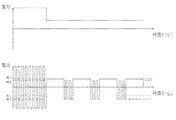
図5に調光機能を有する点灯装置で高圧放電ランプを点灯させたときの電流波形の一例を示す。
同図に示すように、定格電力点灯をしているときに調光電力点灯指令信号がオンになると、電極を定格電力点灯の60−80%程度に低下させて、ランプを点灯させる。
On the other hand, as projectors have become smaller and used in general households in recent years, it is necessary to consider that the screen does not become too bright according to the brightness of the usage environment and the type of image to be projected. It has become. In order to meet such a demand, a projector having a so-called dimming function has been devised (for example, Patent Document 3). Here, the dimming function refers to a function of adjusting the brightness of the lamp, reducing power consumption, and the like by turning on the high-pressure discharge lamp with power lower than the rated power. Hereinafter, lighting with power lower than the rated power is referred to as “dimming power lighting”.
Current high-pressure discharge lamp lighting devices are generally equipped with both "rated power lighting" and "dimming power lighting". In this specification, "rated power lighting" and "dimming power lighting" It is defined that the lamp is lit in the steady power lighting mode. Further, the “dimming power lighting” is generally operated with 60 to 80% of the power of the “rated power lighting”.
FIG. 5 shows an example of a current waveform when a high pressure discharge lamp is lit by a lighting device having a dimming function.
As shown in the figure, when the dimming power lighting command signal is turned on while the rated power is on, the electrode is lowered to about 60-80% of the rated power lighting to light the lamp.
更には最近において画面への投射そのものを必要としない場合には一時的に投射させない、例えばAVミュートといった機能を持ったプロジェクタも考案されている。
こういった機能は放電ランプが消灯直後は内部圧力が高いために再点灯が出来ないため、機械的にシャッターする場合や液晶パネルに印可される電圧を調整し、スクリーンに投射される光を遮断するなどして対応している。以下、画面を意図的に投射させない状態でランプを点灯させることを小電力点灯モードと規定する。
Furthermore, recently, a projector having a function such as an AV mute has been devised which is not temporarily projected when projection onto the screen itself is not required.
These functions cannot be re-lighted immediately after the discharge lamp is extinguished, because the internal pressure is high, so the light applied to the screen is blocked by mechanically shuttering or adjusting the voltage applied to the liquid crystal panel. It corresponds by doing. Hereinafter, turning on the lamp without intentionally projecting the screen is defined as a low power lighting mode.
小電力点灯において電力は極限まで低い電力であることが望ましい。なぜならば、極限まで低い電力で点灯することにより、ランプからの発熱が激減し、プロジェクタからの騒音の主原因である冷却ファンの駆動を停止、または、低下することができ、プロジェクタからの騒音を極限まで小さくすることが出来るからである。更には低い電力で点灯させることでランプの熱的な負荷を軽減することが出来るため、投射が必要な場合と必要としない場合を組み合わせることで実質的なランプ寿命を伸ばすことが可能である。ここでランプの熱的な負荷とは発光管及び電極に対する熱的な負荷であり、これらは投入電力が低いほど小さくすることが出来る。 In low power lighting, it is desirable that the power be as low as possible. This is because by turning on the lamp with extremely low power, the heat generated from the lamp is drastically reduced, and the drive of the cooling fan, which is the main cause of noise from the projector, can be stopped or reduced, reducing the noise from the projector. This is because it can be made as small as possible. Furthermore, since the thermal load of the lamp can be reduced by lighting at low power, it is possible to extend the substantial lamp life by combining the case where projection is necessary and the case where projection is not necessary. Here, the thermal load of the lamp is a thermal load on the arc tube and the electrode, and these can be made smaller as the input power is lower.
また、プロジェクタの性能の一つにコントラスト比がある。これは投影された画面が白の状態(明状態)と黒の状態(暗状態)で画面上の輝度を比較し、その比率を指すものである。コントラスト比が高いことで明暗のはっきりした画像を投影することが出来るため、明るさとともにプロジェクタの重要な性能とされている。現在、コントラスト比を高くするために前述した機械的なシャッター機能などを取り付けて黒の状態を作り出す技術(アイリス機能)が採用されている。
上記のように定格電力では一定以上の明るさが必要であるとともに調光電力点灯が可能であり、更に調光電力を究極に絞った小電力点灯が可能な高圧水銀ランプが求められている。
Further, one of the performances of the projector is a contrast ratio. It compares the brightness on the screen by projected screen is white state (bright state) and a black state (dark state), it is intended to refer to the ratio. Since the contrast ratio is high, it is possible to project a bright and dark image, which is regarded as an important performance of the projector as well as the brightness. Currently, techniques to produce a black state by attaching a like mechanical shutter functions described above in order to increase the contrast ratio (iris function) is employed.
As described above, there is a need for a high-pressure mercury lamp that requires a certain level of brightness at the rated power, can be lit with dimming power, and can be lit with low power with the dimming power ultimately reduced.
上述したように、電力を究極に絞った小電力点灯が可能な高圧水銀ランプが求められているが、矩形波交流電流を供給した状態でそのまま大きく電力を下げて使用した場合、下記の問題が発生した。
この種の高圧水銀ランプは、点灯中、電極先端部に突起を形成させて、当該突起を起点として安定なアーク放電を形成させることが例えば特許文献4に記載されている。
特許文献4によれば、ランプ電圧に応じて或いはランプ点灯電力に応じて定常周波数及び間欠的(周期的)に挿入する低周波の周波数や波の数を変化させることでアーク起点となる突起を維持することで安定した動作が出来ると記載されている。
As described above, there is a demand for a high-pressure mercury lamp that can be operated with low power with the power reduced to the minimum. However, when the rectangular power supply is supplied and the power is greatly reduced, the following problems occur. Occurred.
In this type of high-pressure mercury lamp, for example,
According to
しかしながら、上記技術によって、高圧放電ランプを例えば定格電力180Wのランプを90Wで点灯した場合、如何なる周波数を組み合わせた場合においてもアーク輝点が安定せず、いわゆるフリッカー現象および立ち消えが多々発生した。特に定格電力180Wに対して70W以下では顕著にフリッカーが発生し、30W以下では立ち消えが発生した。
この発明が解決しようとする課題は、ランプ点灯電力が極めて低い、定格消費電力に対して50%以下の電力値でランプ駆動する小電力点灯モードの場合においても放電ランプのアーク輝点を位置的に安定させて、いわゆるフリッカーの発生を防止し、更には電極の変形を抑制することで画面投射モードでの点灯動作に影響を与えることの無く、極めて低い電力においても安定して動作させることができ、小電力モードから定常電力点灯モードに移行する際に立ち消えることなく点灯することができる点灯装置および当該高圧放電ランプ点灯装置を搭載したプロジェクタを提供することである。
However, when the high-pressure discharge lamp is lit at 90 W, for example, with the above-mentioned technique, the arc bright spot is not stable regardless of the combination of frequencies, and so-called flicker phenomenon and disappearance often occur. In particular, flicker was noticeably generated at 70 W or less with respect to the rated power of 180 W, and disappearance was observed at 30 W or less.
The problem to be solved by the present invention is that the arc luminescent spot of the discharge lamp is positioned even in the low power lighting mode in which the lamp driving power is extremely low and the lamp is driven at a power value of 50% or less of the rated power consumption. To prevent the occurrence of so-called flicker, and further suppress the deformation of the electrodes, so that the lighting operation in the screen projection mode is not affected and can be operated stably even at extremely low power. It is possible to provide a lighting device that can be turned on without going off when shifting from the low power mode to the steady power lighting mode, and a projector equipped with the high pressure discharge lamp lighting device.
まず、本願発明者らは、上記した従来の調光点灯電力よりも更に低い電力で動作させた場合について交流駆動動作でフリッカー現象が発生する様子を観察する為、電力を徐々に低下させた場合のアーク輝点部分を観察した。例えば180Wで定格動作しているランプを徐々に電力を変化させていくと定格動作と同じ周波数(これを定格周波数と呼ぶ)であれば、140Wでアーク輝点部を形成している突起部分が変形していくことを見出した。更には特許文献4に基づき、調光時の動作周波数(これを調光周波数)を定格動作周波数よりも低い周波数を選択し、更には間欠的に低周波を挿入することで130Wまでは安定して動作する周波数を見出すことが出来たが、更に電力を下げた場合にはどの周波数を選択しても突起部分が変形していくことが判明した。
First, the inventors of the present application have observed that the flicker phenomenon occurs in the AC drive operation when operating at a power lower than the above-described conventional dimming lighting power. The arc bright spot part of was observed. For example, if the power of a lamp that is rated at 180 W is gradually changed, and the frequency is the same as that of the rated operation (this is referred to as the rated frequency), the protrusion that forms the arc bright spot at 140 W I found out that it would transform. Furthermore, based on
この突起部分の変形について図3を用いて説明する。図3は高圧放電ランプの発光管部分を模式的に示したものであり、20は電極、Aは電極20間に形成されているアークである。高圧放電ランプを定格電力で点灯する場合においては、電極材料であるタングステンが点灯時の熱で蒸発し、発光管の管壁に付着することによる発光管黒化現象を抑制するため、ハロゲンサイクルを促進すべく発光管内にハロゲン物質を封入している。蒸発したタングステンはハロゲンと化合し、対流でアークプラズマに戻ってきたときに解離してプラスイオンとなる。プラスイオンとなったタングステンは、陰極フェーズ側の電極先端の電界集中点であるアークスポットを中心とする領域に引き寄せられ、そこへ堆積する。次に、この電極が陽極フェーズに反転すると、電極先端の全体に電子が衝突し、電極温度は上昇し、陰極フェーズで堆積したタングステンは再び蒸発する。
The deformation of the protruding portion will be described with reference to FIG. FIG. 3 schematically shows the arc tube portion of the high-pressure discharge lamp, in which 20 is an electrode and A is an arc formed between the
定格電力点灯時は、この堆積と蒸発のバランスが、電極先端に適度な突起を維持できるレベルで安定している(図3(a))。しかしながら、調光動作時、即ち定格電力よりも低い電力で点灯している場合には、陰極フェーズ状態の電極先端部の温度が定格電力点灯時よりも低くなるため、電極先端の電界集中点であるアークスポットが突起先端の一部分に限定されるようになる(図3(b))。即ち、突起部の中でも特に電界集中しやすいポイントとそうではないポイントが生じる。アークスポット部分は極めて高温であるため、陰極フェーズであるがタングステンが蒸発し、形状が変形する(図3(c))。変形した形状によってはアークスポット部分の温度が低下し、次にアークスポットを形成しやすい場所へと移動する(図3(d))。こういった現象を繰り返すことで突起全体が台形状に変形し、アークジャンプを繰り返すことが投射画面上のフリッカーとして認識されるものと考えられる。 When the rated power is turned on, the balance between deposition and evaporation is stable at a level that can maintain an appropriate protrusion on the tip of the electrode (FIG. 3A). However, at the time of dimming operation, that is, when lighting at a power lower than the rated power, the temperature at the tip of the electrode in the cathode phase state is lower than that at the time of lighting at the rated power. An arc spot is limited to a part of the tip of the protrusion (FIG. 3B). That is, there are points in the protrusions that are particularly likely to concentrate electric fields and points that are not. Since the arc spot portion is extremely high temperature, in the cathode phase, tungsten evaporates and the shape is deformed (FIG. 3C). Depending on the deformed shape, the temperature of the arc spot portion decreases, and then moves to a place where an arc spot can be easily formed (FIG. 3D). By repeating such a phenomenon, the entire protrusion is deformed into a trapezoidal shape, and it is considered that repeating the arc jump is recognized as flicker on the projection screen.
こういった現象を回避する為には、そういった観点から低周波を間欠的に挿入することは電極先端の温度を上昇させることは有効であり、挿入する波の数を増やすことでより電極温度を上昇させることが出来るのは容易に想像される。しかしながら、交流駆動の場合、必ず電極温度が上昇する陽極フェーズと低下する陰極フェーズが交互に発生することから温度上昇量にも限界があることが推測される。更には低周波の周波数を低くしすぎた場合、例えば10Hz程度とした場合、極性が反転するときの電流の変化が視認されることで投影した画面が明滅したように見える別事象のフリッカー現象が発生してしまう。 In order to avoid such a phenomenon, it is effective to raise the temperature at the tip of the electrode by intermittently inserting a low frequency from such a viewpoint, and the electrode temperature can be increased by increasing the number of waves to be inserted. It is easily imagined that it can be raised. However, in the case of AC driving, the anode phase in which the electrode temperature rises and the cathode phase in which the electrode temperature rises alternately occur, so it is estimated that there is a limit to the amount of temperature rise. Furthermore, if the frequency of the low frequency is made too low, for example, about 10 Hz, the flicker phenomenon of another event in which the projected screen appears to flicker by visually recognizing the change in current when the polarity is reversed. Will occur.
電力を30W程度まで絞ったときに立ち消え現象がどのように発生するかを確認した。電力を定常電力点灯から小点灯に切り替えた直後は問題なく点灯するが、およそ10秒程度で立ち消えが発生した。ランプ電圧を確認するとランプ電圧が200V程度まで上昇し、その結果、バラストが異常電圧と判断してランプを消灯していることが分かった。一方、電極の様子を観察すると電極温度が極めて低くなることで熱電子放出できず、電極全体で放電する所謂グロー放電が持続していることが分かった。一般的に電極先端部の突起で放電するアーク放電に比べてグロー放電はランプ電圧が高くなり、およそ150〜200V程度に至ることが分かっている。 It was confirmed how the phenomenon disappeared when the power was reduced to about 30 W. Immediately after the power was switched from steady-state lighting to small lighting, it turned on without any problem, but it disappeared in about 10 seconds. When the lamp voltage was confirmed, the lamp voltage increased to about 200 V. As a result, it was found that the ballast was judged to be an abnormal voltage and the lamp was turned off. On the other hand, when the state of the electrode was observed, it was found that since the temperature of the electrode was extremely low, thermionic emission could not be performed, and so-called glow discharge that discharges the entire electrode continued. In general, it has been found that the glow discharge has a higher lamp voltage than the arc discharge that is discharged at the protrusion at the tip of the electrode, and reaches approximately 150 to 200V.
次に、小電力点灯モードから定常電力点灯モードに移行する際の立ち消え現象がどのように発生するかを確認した。定常電力点灯モードから移行して、5分程度の短時間であれば、陽極動作している側の電極突起に大きな変化は観られない、この様子を(図4(a))に現す。時間が5分を超え1時間を過ぎる頃には(図4(b))のように、突起が損耗していき小さく丸くなってくる。更に放置し、20時間以上経過すると(図4(c))のように突起が消滅してしまう。意図的に、長時間に渡り小電力点灯モードで放置しない限り、(図4(c))の状態にはならい。即ち、小電力点灯モードから定常電力点灯モードに移行する際の立ち消えは、(図4(c))の電極状態で発生していることになる。
これから、小電力点灯モードから定常電力点灯モードに移行する際の立ち消えは、電極突起の損耗と陽極動作における温度低下が原因となり、移行時に陰極動作に切り替わったとき電極突起の温度が低すぎ放電電流を維持できず立ち消えると考えに至った。
本願発明者らは、以上のように調光電力が非常に低い場合に発生するフリッカー現象及び立ち消えの原因を解明し、加えて、小電力点灯モードから定常電力モードに移行する際の立ち消え、更にこれらの問題を解決する方法について鋭意検討した結果、本願発明に係る高圧放電ランプの点灯方法等に到達したものである。
Next, it was confirmed how the disappearing phenomenon occurred when shifting from the low power lighting mode to the steady power lighting mode. If it is a short time of about 5 minutes after shifting from the steady power lighting mode, a large change is not observed in the electrode protrusion on the anode operating side, and this state is shown in FIG. 4 (a). When the time exceeds 5 minutes and exceeds 1 hour (FIG. 4B), the protrusions wear out and become small and round. Further, the projection disappears as shown in FIG. 4 (c) after 20 hours or more. Unless it is intentionally left in the low power lighting mode for a long time, the state shown in FIG. That is, the extinction at the time of shifting from the low power lighting mode to the steady power lighting mode occurs in the electrode state of FIG. 4 (c).
From this point, the disappearance when shifting from the low power lighting mode to the steady power lighting mode is due to the wear of the electrode protrusion and the temperature drop during anode operation, and the temperature of the electrode protrusion is too low when switching to cathode operation during the transition. It was thought that it could not be maintained and disappeared.
The inventors of the present application have elucidated the flicker phenomenon and the cause of extinction that occur when the dimming power is very low as described above, and in addition, disappeared when shifting from the low power lighting mode to the steady power mode. As a result of intensive studies on a method for solving these problems, the present inventors have reached a lighting method for a high-pressure discharge lamp according to the present invention.
即ち、上記目的を達成するために、本願発明に係る第1の高圧放電ランプの点灯方法は、石英ガラスからなる放電容器に体積のほぼ等しい一対の電極を電極間距離2mm以下で対向配置して、この放電容器に0.15 mg/mm3以上の水銀と、10 − 6 μ mol/mm3〜10−2μ mol/mm3の範囲のハロゲンと所定量の希ガスが封入される高圧放電ランプと、この放電ランプに対して矩形波交流電流を供給して点灯させる給電装置とから構成される高圧放電ランプ点灯装置において、始動直後の初期点灯期間を除いた定格消費電力に対して50%以下の電力値でランプ駆動する小電力点灯モードで動作させる場合、矩形波交流電流の第一の時間単位と第二の時間単位で構成され、交互に繰り返して前記放電ランプを駆動し、第一の時間単位は時間幅t1であるとともに、第二の時間単位は時間幅t2の繰り返しで構成され、且つ5回以上繰り返すことで構成されることを特徴としている。 That is, in order to achieve the above object, a first high-pressure discharge lamp lighting method according to the present invention includes a discharge vessel made of quartz glass and a pair of electrodes having substantially the same volume disposed opposite each other with a distance of 2 mm or less between the electrodes. , and 0.15 mg / mm 3 of mercury in the discharge vessel, 10 - 6 mu pressure discharge mol / mm 3 ~10 -2 μ ranging mol / mm 3 halogen and a predetermined amount of the rare gas is enclosed In a high-pressure discharge lamp lighting device composed of a lamp and a power feeding device that supplies a rectangular wave alternating current to the discharge lamp to light it, 50% of the rated power consumption excluding the initial lighting period immediately after starting When operating in the low power lighting mode in which the lamp is driven at the following power value, the first and second time units of the rectangular wave alternating current are configured, and the discharge lamp is driven alternately and repeatedly. Time unit is hours With a t1, a second time unit is composed of repetition of a time width t2, it is characterized by being constituted by repeating and 5 times or more.
本願の高圧放電ランプには0.15mg/mm3以上の水銀が封入されている。このような高圧放電ランプにおいて定格点灯の50%以下の電力では仮に全く冷却を行なわなかったとしても蒸発できない水銀即ち、未蒸発水銀が発生する。これは本来、照度寿命、明るさといった性能を引き出すために定常電力点灯に耐えうる発光管設計が決まるが、50%以下の電力では冷却が無い環境下においても水銀を蒸発させるに足る発光管温度にはならないためである。従来、未蒸発水銀は放電アークや放電起点を絞るといった作用の働きも低く、動作圧力も低下する結果、光出力を低下させるために好ましくないものと考えられていた。しかしながら、定格点灯の50%以下の電力で動作させたときには放電アーク及び放電起点を絞らない為、一定の電極温度を保つ役割に寄与するため、陰極動作する電極の熱電子放出させ易くしていると推測される。 The high-pressure discharge lamp of the present application contains 0.15 mg / mm 3 or more of mercury. In such a high-pressure discharge lamp, mercury that cannot be vaporized, that is, non-evaporated mercury, is generated even if cooling is not performed at all at an electric power of 50% or less of the rated lighting. Originally, the arc tube design that can withstand steady power lighting is determined in order to bring out the performance such as illuminance life and brightness, but the arc tube temperature is sufficient to evaporate mercury even in an environment where there is no cooling at power of 50% or less. It is because it does not become. Conventionally, non-evaporated mercury has been considered to be unfavorable in order to reduce the light output as a result of the low action of reducing the discharge arc and the starting point of the discharge and the operating pressure. However, since the discharge arc and the discharge starting point are not restricted when operated with power of 50% or less of the rated lighting, it contributes to the role of maintaining a constant electrode temperature, so that thermionic emission of the cathode-operating electrode is facilitated. It is guessed.
ここで一定の時間、極性が固定される点灯方法として直流点灯が考えられる。特にはランプ調光方法として電流が低い場合には直流点灯とすることが特許文献5に記載されている。
Here, DC lighting is considered as a lighting method in which the polarity is fixed for a certain time. In particular,
特許文献5によれば、直流点灯の場合、ランプが消灯してしまうことなく、充分低い電流まで動作が可能であることが記載されている。そこで本願の高圧放電ランプを定格消費電力に対して50%以下の電力値で直流点灯駆動させて確認をした。この場合、30分程度は安定して動作をするものの陰極側の電極先端が変形し、そのあと定常動作に切り替えたときに電圧が大幅に上昇し、スクリーン照度が大きく低下していることが確認された。また、定常動作に切り替える際に立ち消える事も確認された。
ここでこの現象が如何にして生じるのか推察してみた。直流点灯の場合、陰極側の電極先端の温度が交流駆動する定常動作時の温度に比べると著しく低いために電極先端の一部でのみ放電する所謂スポットモードで動作することが特許文献5にも記載されている。安定してスポットモードで動作するため、交流駆動とは違い、アークスポットが移動することは無い。しかしながら、アークスポットとなる部分は非常に狭い領域で溶融しており、非常に高温となっている。数秒といった短時間の動作であれば、大きな影響は無いが、暫く点灯を継続するとアークスポットとなっていた部分が変形する。次に定常動作として例えば定格点灯した場合、変形した電極先端が定格点灯時の電流に耐えられず、更に変形して電圧が大きく上昇する。
このような現象は電極間距離が長く、また水銀密度が低い種類のHIDランプでは発生し得ないかもしれない。しかしながら、本願のように電極間距離が2mm以下と短く、また、0.15mg/mm3以上の水銀が封入された高圧放電ランプの場合、未蒸発水銀があるもののアークは絞られており、定常動作時に比べると低いとしても電極先端部の電流密度は無視できないため、アークスポットの集中が電極の変形を招くと推察される。
また、特許文献6によれば、特許文献5に有るDC型電圧を供給するには、フルブリッジ回路を実現するために半導体デバイスが使用されている、一般的なAC型電圧を供給する駆動ユニットでは、DC型電圧供給を無理に続けると誤動作がもたらせる旨が記載されている。更には、この一般的なAC型電圧を供給する駆動ユニットであっても、DC型電圧供給を行い、放電ランプを安定して点灯できると記載されている。しかしながら、特許文献5で確認された“照度不安定”、“立ち消え”は、依然として残されているのを確認した。
According to
I guessed how this phenomenon occurs. In the case of DC lighting, since the temperature of the electrode tip on the cathode side is remarkably lower than the temperature at the time of steady operation in which AC driving is performed, it is also disclosed in
Such a phenomenon may not occur in a type of HID lamp having a long distance between electrodes and a low mercury density. However, in the case of a high pressure discharge lamp in which the distance between the electrodes is as short as 2 mm or less and mercury of 0.15 mg / mm 3 or more is enclosed as in the present application, the arc is constrained although there is un-evaporated mercury. Even if it is lower than that during operation, the current density at the tip of the electrode is not negligible, so it is assumed that the concentration of the arc spot causes deformation of the electrode.
Further, according to
一方、本願のように交流駆動の矩形波交流電流の第一の時間単位は時間幅t1であるとともに、第二の時間単位は時間幅t2の繰り返しで構成され、且つ5回以上繰り返すことで構成されることで、陰極動作する電極先端のアークスポットが固定されるとともに適当な期間、極性が反転されることで陽極動作する電極先端温度を適正に保つことができるため、長時間安定した動作ができるとともに、小電力点灯モードから定常電力点灯モードに移行する際に立ち消えることが抑制される。 On the other hand, as in the present application, the first time unit of the AC-driven rectangular wave alternating current is the time width t1, and the second time unit is configured by repeating the time width t2, and is configured by repeating five times or more. As a result, the arc spot at the tip of the electrode that operates as a cathode is fixed, and the polarity of the electrode is inverted for an appropriate period, so that the temperature at the tip of the electrode that operates as an anode can be maintained appropriately. In addition, it can be prevented from disappearing when shifting from the low power lighting mode to the steady power lighting mode.
第一の時間幅t1は20ms〜500msで、かつ第二の時間単位の時間幅t2は0.01ms〜5msであった場合、定格消費電力に対して50%以下の電力値でランプ駆動する小電力点灯モードであってもフリッカーの発生を抑制し、安定して動作させることができる。しかしながら、長時間に亘って点灯した場合、僅かながら電極先端が変形し、先端部の突起の位置が変化(ずれ)する場合がある。特に第一の時間幅t1は20ms〜500msで、かつ第二の時間単位の第二の時間幅t2は0.01ms〜5msであってもt1およびt2の期間が長い場合、例えばt2が5ms、t2が500msの場合などは突起部は非常に狭い領域で溶融するものの、溶融部はある大きさを有しており、長時間の点灯の中で僅かながら突起の先端部が変形し、狭い領域で徐々に突起の位置が変化(ずれ)していく。わずかな突起位置のずれは電極間距離が2.0mmよりも長い場合はその変形量の問題は相対的に大きくない。しかしながら、電極間距離が2.0mm以下の極めて短い電極間距離の場合、突起の位置がずれることが、スクリーン照度に影響を及ぼし始める。特にはLCDパネルやDMD(デジタルミラーデバイス)の小型化により、このような僅かな変形も長時間の使用に影響することが分かった。このような結果から、更に長寿命を確保するためにt1,t2の時間を更に厳密に調査した。その結果、第一の時間幅t1は30ms〜100msで、かつ第二の時間単位の第二の時間幅t2は0.05ms〜1msであれば、僅かな突起の位置ずれもなく、長時間に亘って安定して電極先端部を保つことが出来ることが分かった。
また、小電力点灯モードから定常電力点灯モードに移行する際の立ち消えと第二の時間単位の第二の時間幅t2の繰り返し回数について調査を行った。その結果、1回、3回の場合では、立ち消えを完全に抑える事ができなかった。繰り返し回数を5回以上にすることで、立ち消えを完全に抑制出来る事が確認できた。
When the first time width t1 is 20 ms to 500 ms and the time width t2 of the second time unit is 0.01 ms to 5 ms, the lamp is driven at a power value of 50% or less of the rated power consumption. Even in the power lighting mode, it is possible to suppress the occurrence of flicker and to operate stably. However, when the lamp is lit for a long time, the tip of the electrode is slightly deformed, and the position of the protrusion at the tip may change (shift). In particular, the first time width t1 is 20 ms to 500 ms, and the second time width t2 of the second time unit is 0.01 ms to 5 ms, but the period of t1 and t2 is long, for example, t2 is 5 ms, When t2 is 500 ms or the like, the protrusion melts in a very narrow region, but the melted portion has a certain size, and the tip of the protrusion slightly deforms during long-time lighting, resulting in a narrow region. The position of the protrusion gradually changes (shifts). When the distance between the electrodes is longer than 2.0 mm, the problem of the amount of deformation is not relatively large. However, when the interelectrode distance is an extremely short interelectrode distance of 2.0 mm or less, the position of the protrusion starts to affect the screen illuminance. In particular, it has been found that such slight deformation affects long-time use due to miniaturization of LCD panels and DMDs (digital mirror devices). From these results, the times t1 and t2 were investigated more strictly in order to ensure a longer life. As a result, if the first time width t1 is 30 ms to 100 ms and the second time width t2 of the second time unit is 0.05 ms to 1 ms, there is no slight misalignment of the protrusions, and a long time. It was found that the tip of the electrode can be maintained stably over the entire time.
In addition, investigation was made on the number of repetitions of the disappearance and the second time width t2 of the second time unit when shifting from the low power lighting mode to the steady power lighting mode. As a result, the disappearance could not be completely suppressed in the first and third cases. It was confirmed that the disappearance could be completely suppressed by setting the number of repetitions to 5 times or more.
以下に基づき、本発明においては、以下のようにして上記目的を達成する。
(1)石英ガラスからなる放電容器に第一の電極と第二の電極が電極間距離2mm以下で対向配置して、この放電容器に0.15mg/mm3以上の水銀と、10 − 6 μ mol/mm3〜10−2μ mol/mm3の範囲のハロゲンと所定量の希ガスが封入される高圧放電ランプと、この高圧放電ランプに対して矩形波交流電流を供給して点灯させる給電装置とから構成される高圧放電ランプ点灯装置において、前記給電装置は、前記高圧放電ランプに対して、定常電力点灯モードと、定格消費電力に対して50%以下の電力値でランプ駆動する小電力点灯モードとを切り替え可能に駆動するものであって、前記高圧放電ランプに対して100Hz〜5kHzの範囲から選択された定常電力点灯周波数の第一の極性と第二の極性が交互に繰り返す交流電流IHによって駆動される前記定常電力点灯モードと、前記高圧放電ランプに対して、定常電力点灯モードの定格消費電力に対して50%以下の交流電流ILによって駆動される小電力モードで構成され、前記交流電流ILは、第一の時間単位と第二の時間単位で構成され、交互に繰り返して前記放電ランプを駆動し、第一の時間単位は時間幅t1で第一の極性または第二の極性のどちらか一方の極性を持ち、第二の時間単位は、時間幅t2で第一の極性と第二の極性が交互に5回以上繰り返されて動作させる。
(2)上記(1)において、時間幅t1は20ms〜500msであるとともに、かつ第二の時間単位の時間幅t2は0.01ms〜5msとする。
(3)上記(1)において、小電力点灯モードでの駆動時の電流は、第一の時間単位 ≦ 第二の時間単位の関係にある。
(4)上記(1)〜(3)のいずれかの高圧放電ランプ点灯装置を画像を投影する機能を備えたプロジェクタに搭載する。
(5)上記(4)のプロジェクタにおいて、定常電力点灯モードで一定の期間、プロジェクタの画像信号に変化が無い場合に小電力点灯モードに移行する機能を具備する。
(6)上記(4)のプロジェクタにおいて、小電力点灯モードで一定の期間、プロジェクタの画像信号に変化が無い場合に自動的に高圧放電ランプを消灯する機能を具備する。
(7)上記(4)のプロジェクタにおいて、小電力点灯モードで一定の期間動作させた後、検知手段と連動して定常電力点灯動作に移行する機能を具備する。
Based on the following, in the present invention, the above object is achieved as follows.
(1) a discharge vessel made of quartz glass is first electrode and a second electrode disposed opposite the following
(2) In the above (1), the time width t1 is 20 ms to 500 ms, and the time width t2 of the second time unit is 0.01 ms to 5 ms.
(3) In the above (1), the current at the time of driving in the low power lighting mode has a relationship of first time unit ≦ second time unit.
(4) The high pressure discharge lamp lighting device according to any one of (1) to (3) is mounted on a projector having a function of projecting an image.
(5) The projector of (4) above has a function of shifting to the low power lighting mode when there is no change in the image signal of the projector for a certain period in the steady power lighting mode.
(6) The projector of (4) above has a function of automatically turning off the high-pressure discharge lamp when there is no change in the image signal of the projector for a certain period in the low power lighting mode.
(7) The projector of the above (4) has a function of shifting to a steady power lighting operation in conjunction with the detecting means after being operated for a certain period in the low power lighting mode.
本発明においては、以下の効果を得ることができる。
(1)定格消費電力に対して50%以下の電力値でランプ駆動するとき、矩形波交流電流の第一の時間単位と第二の時間単位で構成され、交互に繰り返して前記放電ランプを駆動し、第一の時間単位は時間幅t1であるとともに、第二の時間単位は時間幅t2の繰り返しで構成され、且つ5回以上繰り返すとように動作させたので、放電ランプのアーク輝点を位置的に安定させて、いわゆるフリッカーの発生を防止することができ、極めて低い電力でも立ち消えることなく、安定して点灯させることができる。
(2)矩形波交流電流の時間幅t1は20ms〜500msであるとともに、かつ第二の時間単位の時間幅t2は0.01ms〜5msなるように動作させたので、電極に対する熱的な負荷に偏りが生じるのを防止することで、電極先端部の突起の位置ずれを防止でき、長時間に亘り小電力で動作させても、照度寿命特性を確保することができる。
(3)本発明の高圧放電ランプ点灯装置をプロジェクタに搭載し、定格消費電力に対して50%以下の電力値で前記放電ランプを点灯中に、一定の期間、プロジェクタの画像信号に変化が無い場合に定格消費電力に対して50%以下の電力値でランプ駆動する小電力点灯モードに移行させることにより、無駄な電力の消費を防ぎ、省電力化を図ることができる。
(4)本発明の高圧放電ランプ点灯装置をプロジェクタに搭載し、定格消費電力に対して50%以下の電力値でランプ駆動する小電力点灯モードで前記放電ランプを点灯中に、一定の期間、プロジェクタの画像信号に変化が無い場合に自動的に高圧放電ランプを消灯することにより、プロジェクタの消し忘れを防止することができる。
(5)本発明の高圧放電ランプ点灯装置をプロジェクタに搭載し、定格消費電力に対して50%未満の電力値で前記放電ランプを点灯中に、検知手段と連動してプロジェクタを点灯させることで無駄な電力の消費を防ぎ、省電力化を図ることができる。
In the present invention, the following effects can be obtained.
(1) When the lamp is driven at a power value of 50% or less with respect to the rated power consumption, the discharge lamp is driven by being alternately constituted by a first time unit and a second time unit of a rectangular wave alternating current. The first time unit is the time width t1, and the second time unit is composed of repetition of the time width t2, and is operated so as to be repeated five times or more. It is possible to prevent the occurrence of so-called flicker by being stabilized in position, and can be lit stably without being extinguished even with extremely low power.
(2) Since the time width t1 of the rectangular wave alternating current is 20 ms to 500 ms, and the time width t2 of the second time unit is 0.01 ms to 5 ms, the thermal load on the electrode is reduced. By preventing the occurrence of bias, it is possible to prevent the positional deviation of the protrusions at the tip of the electrode, and it is possible to ensure the illuminance life characteristics even when operated with low power for a long time.
(3) When the high-pressure discharge lamp lighting device of the present invention is mounted on a projector and the discharge lamp is lit at a power value of 50% or less of the rated power consumption, there is no change in the image signal of the projector for a certain period. In this case, by switching to the low power lighting mode in which the lamp is driven with a power value of 50% or less with respect to the rated power consumption, wasteful power consumption can be prevented and power saving can be achieved.
(4) The high-pressure discharge lamp lighting device of the present invention is mounted on a projector, and the discharge lamp is lit in a low power lighting mode in which the lamp is driven at a power value of 50% or less of the rated power consumption. By automatically turning off the high-pressure discharge lamp when there is no change in the image signal of the projector, forgetting to turn off the projector can be prevented.
(5) By mounting the high pressure discharge lamp lighting device of the present invention on a projector and lighting the discharge lamp at a power value of less than 50% of the rated power consumption, the projector is turned on in conjunction with the detection means. It is possible to prevent wasteful power consumption and save power.
以下、本発明の実施の形態について説明する。
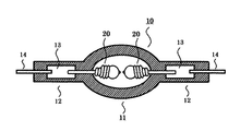
図1に本発明の対象となる高圧放電ランプを示す。
高圧放電ランプ10は、石英ガラスからなる放電容器によって形成された概略球形の発光部11を有する。この発光部11の中には一対の電極20が2mm以下の間隔で対向配置している。また、発光部11の両端部には封止部12が形成される。この封止部12には、モリブデンよりなる導電用金属箔13が、例えばシュリンクシールにより気密に埋設される。金属箔13の一端には電極20の軸部が接合しており、また、金属箔13の他端には外部リード14が接合して外部の給電装置から給電が行なわれる。
発光部11には、水銀と、希ガスと、ハロゲンガスが封入されている。水銀は、必要な可視光波長、例えば、波長360〜780nmの放射光を得るためのもので、0.15mg/mm3以上封入されている。この封入量は、温度条件によっても異なるが、点灯時200 気圧以上で極めて高い蒸気圧となる。また、水銀をより多く封入することで点灯時の水銀蒸気圧250気圧以上、300気圧以上という高い水銀蒸気圧の放電ランプを作ることができ、水銀蒸気圧が高くなるほどプロジェクタ装置に適した光源を実現できる。
Embodiments of the present invention will be described below.
FIG. 1 shows a high-pressure discharge lamp which is an object of the present invention.
The high-
The light emitting unit 11 is filled with mercury, rare gas, and halogen gas. Mercury is used to obtain a necessary visible light wavelength, for example, radiation having a wavelength of 360 to 780 nm, and 0.15 mg / mm 3 or more is enclosed. Although the amount of the sealing varies depending on the temperature condition, the vapor pressure becomes extremely high at 200 atm or more at the time of lighting. In addition, by enclosing more mercury, it is possible to make a discharge lamp with a high mercury vapor pressure of 250 atm or more and 300 atm or more at the time of lighting, and the higher the mercury vapor pressure, the more suitable the light source suitable for the projector device. realizable.
希ガスは、例えば、アルゴンガスが約13kPa封入される。その機能は点灯始動性を改善することにある。ハロゲンは、沃素、臭素、塩素などが水銀あるいはその他の金属と化合物の形態で封入される。ハロゲンの封入量は、10−6μmol/mm3〜10−2μmol/mm3の範囲から選択される。ハロゲンの機能は、いわゆるハロゲンサイクルを利用した長寿命化であるが、本発明の高圧放電ランプのように極めて小型できわめて高い点灯蒸気圧のものは、放電容器の失透防止をいう作用もある。
高圧放電ランプの数値例を示すと、例えば、発光部の最大外径9.4mm、電極間距離1.0mm、発光管内容積55mm3、定格電圧70V、定格電力180Wであり交流点灯される。
As the rare gas, for example, argon gas is sealed at about 13 kPa. Its function is to improve the lighting startability. As for halogen, iodine, bromine, chlorine and the like are enclosed in the form of mercury or other metals and compounds. The amount of halogen encapsulated is selected from the range of 10 −6 μmol / mm 3 to 10 −2 μmol / mm 3 . The function of the halogen is to extend the life by using a so-called halogen cycle. However, an extremely small and extremely high lighting vapor pressure such as the high-pressure discharge lamp of the present invention also has an effect of preventing devitrification of the discharge vessel. .
As an example of numerical values of the high-pressure discharge lamp, for example, the maximum outer diameter of the light emitting part is 9.4 mm, the distance between the electrodes is 1.0 mm, the inner volume of the arc tube is 55 mm 3 , the rated voltage is 70 V, and the rated power is 180 W.
また、この種の放電ランプは、小型化するプロジェクタ装置に内蔵されるものであり、全体寸法として極めて小型化が要請させる一方で高い発光光量も要求される。このため、発光部内の熱的影響は極めて厳しいものとなる。ランプの管壁負荷値は0.8〜2.5W/mm2、具体的には2.4W/mm2となる。
このような高い水銀蒸気圧や管壁負荷値を有することがプロジェクタ装置やオーバーヘッドプロジェクタのようなプレゼンテーション用機器に搭載された場合に、演色性の良い放射光を提供することができる。
In addition, this type of discharge lamp is built in a projector apparatus that is miniaturized, and requires a large amount of light emission while requiring an extremely small overall size. For this reason, the thermal influence in the light emitting part is extremely severe. The lamp wall load value of the lamp is 0.8 to 2.5 W / mm 2 , specifically 2.4 W / mm 2 .
When such a high mercury vapor pressure or tube wall load value is mounted on a presentation device such as a projector device or an overhead projector, emitted light with good color rendering can be provided.
図2は電極先端と突起を示すことを目的として、図1に示す電極20の先端を模式化して表したものである。電極20は、それぞれ球部20aと軸部20bから構成され、球部20aの先端に突起21が形成されている。
ここで、上記突起21は、本発明に係る放電ランプのように電極間距離2 m m 以下であって発光部に0.15mg / mm 3 以上の水銀を含むプロジェクタ装置の光源として用いられる場合は不可欠となる。なぜなら、発光部に0.15mg / mm 3 以上の水銀を含み、動作圧力が200気圧以上に達する放電ランプにおいては、高い蒸気圧によって、アーク放電が小さく絞られ、結果として放電起点も小さく絞られるからである。
また、電極先端に突起21が形成されることで、そこを起点としてアーク放電が発生するため、アークからの光が電極の球部2 0 a によって遮られにくくなる。このため、光の利用効率が向上し、より明るい映像が得られるという利点も生じる。なお、図2 は模式化した図面ではあるが、通常、軸部2 0 b の先端には、軸径より大きい径を有する球部に相当する要素を有している。
FIG. 2 schematically shows the tip of the
Here, when the
In addition, since the
次に上記放電ランプを点灯させる給電装置を図5示す。
点灯装置は放電ランプ10と給電装置から構成される。給電装置は、直流電圧が供給される降圧チョッパ回路1と、降圧チョッパ回路1の出力側に接続され直流電圧を交流電圧に変化させて放電ランプ10に供給するフルブリッジ型インバータ回路2(以下、「フルブリッジ回路」ともいう)と、放電ランプに直列接続されたコイルL1、コンデンサC1、およびスタータ回路3と、上記フルブリッジ回路2のスイッチング素子Q1〜Q4を駆動するドライバ4と、制御部5から構成される。
制御部5は例えばマイクロプロセッサ等の処理装置で構成することができ、図5ではその機能構成をブロック図で示している。
Next, FIG. 5 shows a power supply device for lighting the discharge lamp.
The lighting device includes a
The
図5において、降圧チョッパ回路1は、直流電圧が供給される+側電源端子に接続されたスイッチング素子QxとリアクトルLxと、スイッチング素子QxとリアクトルLxの接続点と−側電源端子間にカソード側が接続されたダイオードDxと、リアクトルLxの出力側に接続された平滑コンデンサCxと、平滑コンデンサCxの−側端子とダイオードDxのアノード側の間に接続された電流検出用の抵抗Rxから構成される。
上記スイッチング素子Qxを所定のデューティで駆動することにより、入力直流電圧Vdcをこのデューティに応じた電圧に降圧する。降圧チョッパ回路1の出力側には、電圧検出用の抵抗R1,R2の直列回路が設けられている。
フルブリッジ回路2は、ブリッジ状に接続したスイッチング素子Q1〜Q4から構成され、スイッチング素子Q1、Q4、スイッチング素子Q2、Q3を交互にオンにすることにより、スイッチング素子Q1、Q2の接続点と、スイッチング素子Q3、Q4の接続点間に矩形波状の交流電圧が発生する。
スタータ回路3は、抵抗R3とスイッチング素子Q5の直列回路と、コンデンサC2とトランスT1から構成される。
スイッチング素子Q5をオンにすると、コンデンサC2に充電されていた電荷がスイッチング素子Q5、トランスT1の一次側巻線を介して放電し、トランスT1の二次側にパルス状の高電圧が発生する。この高電圧は、放電ランプ10の補助電極Etに印加され、ランプを点灯する。
In FIG. 5, the step-down chopper circuit 1 includes a switching element Qx and a reactor Lx connected to a + side power supply terminal to which a DC voltage is supplied, and a cathode side between a connection point of the switching element Qx and the reactor Lx and a minus side power supply terminal. It comprises a connected diode Dx, a smoothing capacitor Cx connected to the output side of the reactor Lx, and a current detection resistor Rx connected between the negative side terminal of the smoothing capacitor Cx and the anode side of the diode Dx. .
By driving the switching element Qx with a predetermined duty, the input DC voltage Vdc is stepped down to a voltage corresponding to the duty. On the output side of the step-down chopper circuit 1, a series circuit of voltage detection resistors R1 and R2 is provided.
The
The starter circuit 3 includes a series circuit of a resistor R3 and a switching element Q5, a capacitor C2, and a transformer T1.
When the switching element Q5 is turned on, the electric charge charged in the capacitor C2 is discharged via the switching element Q5 and the primary side winding of the transformer T1, and a pulsed high voltage is generated on the secondary side of the transformer T1. This high voltage is applied to the auxiliary electrode Et of the
上記回路において、第一の時間単位は時間幅t1であるとともに、第二の時間単位は時間幅t2の繰り返しで構成され、且つ5回以上繰り返すことで構成されるように動作させるにはフルブリッジ回路2のスイッチング素子Q1〜Q4のスイッチング周期を調整することで達成でき、また、出力電圧は降圧チョッパ回路1のスイッチング素子Qxの動作デューティを調整することで達成できる。
降圧チョッパ回路1のスイッチング素子Qxは、ゲート信号Gxのデューティに応じてオン/オフし、ランプ10に供給される電力が変化する。すなわち、電力アップならQxのデューティを下げるなどして、その入力された電力調整信号値に合致する電力値になるようにゲート信号Gxの制御を行う。
これにより、出力される電流波形を図7に示す。
In the above circuit, the first time unit is the time width t1, and the second time unit is configured by repeating the time width t2 and is operated by being repeated five times or more. This can be achieved by adjusting the switching period of the switching elements Q1 to Q4 of the
The switching element Qx of the step-down chopper circuit 1 is turned on / off according to the duty of the gate signal Gx, and the power supplied to the
Thus, the output current waveform is shown in FIG.
制御部5は、駆動信号発生手段51とコントローラ52から構成される。
駆動信号発生手段51は、例えば交流信号発生部51a〜51c、第一の時間単位は時間幅t1であるとともに、第二の時間単位は時間幅t2の繰り返しで構成され、且つ5回以上繰り返すことで構成されるように駆動期間が非対称な矩形波を発生させる非対称矩形波信号発生部51cと、これらの出力を選択するセレクタ51dから構成される、交流信号発生部51a〜51b、非対称矩形波発生部51cの出力を選択的に出力し、フルブリッジ回路2のスイッチング素子Q1〜Q4を駆動するための駆動信号を発生する。
コントローラ52は、ランプ10の点灯動作を制御する点灯動作制御部52aと、外部からの点灯電力指令に応じて、降圧チョッパ回路1のスイッチング素子Qxを設定されたデューティで駆動し、ランプ電力を制御する電力制御部52cを備える。
また、上記スイッチング素子Q1〜Q4の駆動信号を設定するため、定常電力点灯か、0.5×P(W)以下の電力で動作させる小電力点灯かに応じて上記駆動信号発生手段51のセレクタに周波数選択指令を送出する周波数選択部52bを備える。
The
The drive signal generating means 51 is, for example, AC
The
Further, in order to set the drive signals for the switching elements Q1 to Q4, the selector of the drive signal generating means 51 according to whether steady power lighting or low power lighting operated with power of 0.5 × P (W) or less. Includes a
電力制御部52 cは、電流検出用の抵抗Rxの両端電圧と、電圧検出用の抵抗R1、R2により検出された電圧から、ランプ電流I、ランプ電圧Vを求めてランプ電力を演算し、この電力が点灯電力指令に一致するような降圧チョッパ回路1のスイッチング素子Qxのデューティを制御する。
セレクタ51dは、周波数選択部52bからの指令に応じて、交流信号発生部51a〜51b、非対称矩形波信号発生部51cの出力を選択的にドライバ4に送出する。
なお、周波数選択部52bから出力される非対称比率増減信号に応じて、非対称矩形波信号発生部51cから出力される矩形波の時間幅t1を第二の時間単位の時間幅t2の値に応じて増減してもよい。
更には、第一の時間単位における放電ランプ点灯電力と第二の時間単位における放電ランプ点灯電力を
第一の時間単位 ≦ 第二の時間単位
となるように変化させても良い。これは、陽極として動作している電極突起部の温度上昇を改善することになる。
ここで定常電力点灯から小電力点灯に移行する際には定格消費電力に対して50%以下の電力から徐々に電力を低下させながら小点灯電力に移行しても良い。そうすることで電極温度の急激な変化を更に抑えることが出来る。この場合には降圧チョッパ回路1のスイッチング素子Qxのデューティを制御して電力を徐々に減じながら、小電力点灯に移行することで実現される。
また、後述するように、小電力点灯から定常電力点灯に移行する際、徐々に動作電力を増大させたり、陽極動作していた電極側の陽極駆動期間を徐々に小さくしながら(Tb/Taを変化させながら)、定常電力点灯に移行させる場合には、電力制御部52cでランプに供給する電力を徐々に増加させたり、非対称矩形波信号発生部51cに送出される非対称比率増減信号により、矩形波の非対称率を制御する。
The
The selector 51d selectively sends the outputs of the
In addition, according to the asymmetric ratio increase / decrease signal output from the
Furthermore, the discharge lamp lighting power in the first time unit and the discharge lamp lighting power in the second time unit may be changed so that the first time unit ≦ the second time unit. This will improve the temperature rise of the electrode protrusion acting as the anode.
Here, when shifting from steady power lighting to low power lighting, the power may be shifted to low lighting power while gradually decreasing the power from 50% or less of the rated power consumption. By doing so, a rapid change in the electrode temperature can be further suppressed. In this case, it is realized by controlling the duty of the switching element Qx of the step-down chopper circuit 1 to shift to low power lighting while gradually reducing the power.
As will be described later, when shifting from low power lighting to steady power lighting, the operating power is gradually increased or the anode driving period on the electrode side where the anode has been operated is gradually decreased (Tb / Ta is reduced). In the case of shifting to steady power lighting, the
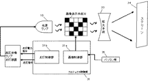
ここで本実施例に係る高圧放電ランプ点灯装置を搭載したプロジェクタの構成例を図6に示す。
プロジェクタは、上述した高圧放電ランプ点灯装置30及び高圧放電ランプ10と、プロジェクタ制御部31と、液晶表示装置等から構成される画像表示装置32と、画像表示装置32に表示された画像を拡大表示する拡大装置33から構成され、拡大装置33により拡大された画像は、スクリーン32に投影表示される。
プロジェクタ制御部31は、パソコン35あるいはテレビなどの外部装置から与えられる画像信号を処理する画像制御部31aと、上述した高圧放電ランプ点灯装置30に、点灯指令及び点灯電力指令を送出する点灯制御部31bを備える。
FIG. 6 shows a configuration example of a projector equipped with the high pressure discharge lamp lighting device according to the present embodiment.
The projector displays the high-pressure discharge lamp lighting device 30 and the high-
The projector control unit 31 includes an
次に、定常電力点灯動作モードから本実施例の小電力モードへの切り替え制御について説明する。ここで定常電力点灯モードとは、「定格電力」、「調光電力」で動作させる場合を指す。なお、「調光電力」の点灯電力は高圧放電ランプ及び給電装置の設計によって決まるものであるが、「調光電力」とは「定格電力」に対しておよそ60〜80%程度の電力で動作させることである。
制御部5に与えられる点灯電力指令信号により、小電力モードが選択されると、図5に示す制御部5は第一の時間単位は時間幅t1であるとともに、第二の時間単位は時間幅t2の繰り返しで構成され、且つ5回以上繰り返す構成となるような駆動期間が非対称な矩形波を発生させる、非対称矩形波を選択する。すなわち、周波数選択部52bは、セレクタ51dにより非対称矩形波信号発生部51cの出力を選択させ、ドライバ4は、スイッチング阻止Q1〜Q4に非対称矩形波の駆動信号を与え、Q1、Q4、或いはQ3、Q2を交互にオンする時間を非対称にすることで、高圧放電ランプ10を非対称矩形波駆動する。
また、点灯電力指令信号が定常電力点灯モードを選択した場合には、矩形波交流点灯で点灯動作する。すなわち、周波数選択部52bは、セレクタ51dにより交流信号発生部51a、51bの出力を選択させ、ドライバ4は、スイッチング素子Q1〜Q4に交流駆動信号を与え、スイッチング素子Q1、Q4、或いはQ3、W2を交互にオンにして高圧放電ランプ10に交流矩形波電流を供給する。
Next, switching control from the steady power lighting operation mode to the low power mode of this embodiment will be described. Here, the steady power lighting mode refers to the case of operating with “rated power” and “dimming power”. The lighting power of “Dimming power” is determined by the design of the high-pressure discharge lamp and the power supply device, but “Dimming power” operates at a power of about 60 to 80% of the “rated power”. It is to let you.
When the low power mode is selected by the lighting power command signal given to the
When the lighting power command signal selects the steady power lighting mode, the lighting operation is performed with rectangular wave AC lighting. That is, the
図7で示す電流波形で駆動した実際の評価結果を表1に示す。点灯回路の条件は、
t1=50ms,2=0.1ms,t2を5回繰り返す,前記180Wランプを使用し、定格ランプ入力;180Wで評価を行った。
評価結果を表1に示す。表1は、小電力点灯モードである100W〜140Wの範囲で変化させ、各電力値における点灯の可否、電極損耗、フリッカー及び突起の位置ずれ有無を調べたものである。ここで表中の判定基準は以下のとおりとしている。◎とは点灯可能な状態でフリッカーがなく、かつ電極先端部の損耗が無いだけでなく、突起の位置ずれもんく、長時間に亘って安定して動作が可能なことを示す。○とは点灯可能な状態でフリッカーがなく、かつ電極先端部の損耗は無いが、長時間の点灯では突起の位置ずれを生じ、4000時間超の照度維持特性が必要な長寿命ランプへの適用が困難であることを示す。×は点灯そのもの不可能な状態、または点灯可能な状態であっても電極損耗が大きい、フリッカーなどの現象により正常な使用ができないことを示す。
表1に示されるように、定格電力の11%よりも低い電力では、点灯を持続することができなかった。これは極性が陰極側でどうさする側の電極温度が極端に低くなるために、十分な熱電子放出ができないために放電を維持できなくなり、グロー放電となることで異常電圧と検知され保護回路が働いたと考えられる。また、定格電力の50%よりも高い電力では、長時間、陽極側で動作し電極温度が高くなりすぎたため突起が消失した。このため本件発明の範囲を11%〜50%から選択した電力で点灯させる場合のみフリッカーもなく、電極先端部の突起の消失もなく、小電力点灯モードから定常電力点灯モードへの移行時の立ち消えもなく良好な点灯状態を構成することができた。
Table 1 shows the actual evaluation results driven with the current waveform shown in FIG. The condition of the lighting circuit is
T1 = 50 ms, 2 = 0.1 ms, t2 was repeated five times, the 180 W lamp was used, and the rated lamp input was evaluated at 180 W.
The evaluation results are shown in Table 1. Table 1 shows changes in the range of 100 W to 140 W in the low power lighting mode, and examines whether or not lighting is possible, electrode wear, flicker and protrusion misalignment at each power value. Here, the criteria in the table are as follows. The symbol “◎” indicates that the lamp can be lit and has no flicker, the electrode tip is not worn, and the protrusions are not misaligned. ○ is applicable to long-life lamps that can be lit and have no flicker and no electrode tip wear, but long-time lighting results in misalignment of protrusions and requires illuminance maintenance characteristics of over 4000 hours Is difficult. X indicates that lighting cannot be performed normally, or even when lighting is possible, electrode wear is large, and normal use cannot be performed due to a phenomenon such as flicker.
As shown in Table 1, lighting could not be continued with power lower than 11% of the rated power. This is because the electrode temperature on the side where the polarity is on the cathode side becomes extremely low, so it is impossible to maintain the discharge because sufficient thermionic emission is not possible, and it is detected as an abnormal voltage due to glow discharge and a protection circuit Seems to have worked. Further, when the power was higher than 50% of the rated power, the protrusions disappeared because the electrode temperature was too high due to the operation on the anode side for a long time. For this reason, there is no flicker, no loss of protrusions at the tip of the electrode, and extinction at the time of transition from the low power lighting mode to the steady power lighting mode only when the range of the present invention is turned on with power selected from 11% to 50%. It was possible to construct a good lighting state.

ところで、小電力点灯時には、ランプに非対称な矩形波電流を供給する必要があり、図5に示したフルブリッジ回路2のスイッチング素子Q1〜Q4に非対称矩形波の駆動信号を与え、Q1、Q4、或いはQ3、Q2を交互にオンする時間を非対称にする必要がある。
実際の回路構成においては、例えばコンデンサを充電することで、スイッチング素子Q1、Q2へのハイレベルのゲート駆動信号を生成している。この場合、上記コンデンサが放電してしまうので、長時間に亘り、スイッチング素子Q1、Q3をオン状態に保つことは難しく、周期的にコンデンサを充電する必要がある。このようなコンデンサを用いた駆動回路を用いた場合、コンデンサを充電する期間、スイッチング素子Q1、Q3は一時的にオフとなり、周期的な極性反転動作が行われることとなる。ここでコンデンサが充電される期間はコンデンサの容量にもよるが、およそ0.1ms程度である。したがって、極性反転期間、即ち駆動期間Tbはおよそ0.1ms程度が望ましい。
仮に直流点灯駆動をしようとした場合には、図5に示したフルブリッジ回路2のスイッチング素子Q1〜Q4に直流の駆動信号を与え、スイッチング素子Q1、Q4、或いはQ3、Q2をオン状態に保つ必要がある。
そのため、スイッチング素子Q1、Q4のゲートG1、G4、或いはQ3、Q2のゲートG3、G2にハイレベルの信号を継続的に与える必要があり、スイッチング素子Q1、Q3のゲート駆動信号には、スイッチング素子Q2、Q4のゲート駆動信号より、ハイレベルの電圧を印加する必要がある。
スイッチング素子Q1、Q3のゲートG1、G3に供給するハイレベルの駆動信号は、別電源を用いるか、或いは、チャージポンプ回路などを用いて生成することも考えられるが、部品点数も増加し、コストも増加する。
したがって、第一の時間単位は時間幅t1であるとともに、第二の時間単位は時間幅t2の繰り返しで構成され、且つ5回以上繰り返すことで構成される矩形波点灯駆動させることは、実際の回路構成においても、特別に部品点数を増やすことなく、安価に点灯回路を構成することができる。
By the way, at the time of low power lighting, it is necessary to supply an asymmetric rectangular wave current to the lamp, and an asymmetric rectangular wave driving signal is given to the switching elements Q1 to Q4 of the
In an actual circuit configuration, for example, a high-level gate drive signal to the switching elements Q1 and Q2 is generated by charging a capacitor. In this case, since the capacitor is discharged, it is difficult to keep the switching elements Q1 and Q3 on for a long time, and it is necessary to charge the capacitor periodically. When such a driving circuit using a capacitor is used, the switching elements Q1 and Q3 are temporarily turned off during the period of charging the capacitor, and a periodic polarity inversion operation is performed. Here, the period during which the capacitor is charged is approximately 0.1 ms, although it depends on the capacitance of the capacitor. Therefore, the polarity inversion period, that is, the driving period Tb is preferably about 0.1 ms.
If direct current lighting drive is to be performed, a direct current drive signal is given to the switching elements Q1 to Q4 of the
Therefore, it is necessary to continuously give a high level signal to the gates G1 and G4 of the switching elements Q1 and Q4, or the gates G3 and G2 of Q3 and Q2, and the gate drive signals of the switching elements Q1 and Q3 It is necessary to apply a high level voltage from the gate drive signals of Q2 and Q4.
The high-level drive signal supplied to the gates G1 and G3 of the switching elements Q1 and Q3 may be generated using a separate power supply or a charge pump circuit, but the number of parts increases and the cost increases. Will also increase.
Accordingly, the first time unit is the time width t1, and the second time unit is configured by repetition of the time width t2, and the rectangular wave lighting driving configured by repeating five times or more is actually Also in the circuit configuration, the lighting circuit can be configured at low cost without specially increasing the number of parts.
一般的に高圧放電ランプに使用される電極は主にタングステンで構成されており、照度寿命特性を改善する目的で99.999%以上の極めて高純度のタングステンが使用される。高純度のタングステンは不純物が少ないという意味で長寿命を期待できる半面、結晶粒が粗大化するため、脆いという欠点を有している。特に先端部は極めて高温になることから結晶粒が粗大化しやすい。熱的なストレスが急激に加わることで熱応力により結晶粒界間で割れが生じるなどの不具合が生じる。従って、定常電力点灯に移行する場合は交流駆動に移行してから電力を移行させることが望ましい。 In general, an electrode used for a high-pressure discharge lamp is mainly composed of tungsten, and tungsten having an extremely high purity of 99.999% or more is used for the purpose of improving illuminance life characteristics. High-purity tungsten can be expected to have a long life in terms of few impurities, but has the disadvantage of being brittle because the crystal grains become coarse. In particular, since the tip portion is extremely hot, the crystal grains are likely to become coarse. The abrupt application of thermal stress causes problems such as cracking between crystal grain boundaries due to thermal stress. Therefore, when shifting to steady power lighting, it is desirable to shift power after shifting to AC driving.
上記のように制御することで、例えば、パソコンなどの外部信号を通じてプロジェクタからスクリーン面に画像を投影している状態で、画面に変化が無い状態が継続された際などに自動的に小電力モードに移行させることができ、省電力化を図ることができる。
更には、小電力モードへ移行すると共に、高圧水銀ランプの冷却を止めるなどにより、更に省電力を図ることが出来る。また、短い点灯時間で繰り返し使用される環境の場合、始動時のダメージにより高圧放電ランプの寿命時間に悪影響を及ぼすことがある。小電力モードを利用することで高圧放電ランプを消すことなく、連続点灯動作させることで実質的に寿命特性を改善されると共に瞬時に画面を投影することが出来るなどの利点が考えられる。
By controlling as described above, for example, when the image is projected from the projector to the screen surface through an external signal such as a personal computer, the low power mode is automatically activated when the screen remains unchanged. The power can be saved.
Furthermore, it is possible to further save power by shifting to the low power mode and stopping the cooling of the high pressure mercury lamp. In an environment where the lamp is repeatedly used with a short lighting time, the life time of the high-pressure discharge lamp may be adversely affected due to damage at the start. By using the low power mode, there are advantages such that the life characteristics can be substantially improved and the screen can be projected instantaneously by performing the continuous lighting operation without turning off the high pressure discharge lamp.
ここで小電力点灯は画面に投射しないことを主としているが、これに限ったことではない。即ち、投射モードにおいて暗い画面をより暗く映し出すために定格点灯電力の50%未満の電力で動作させることは非常に有効である。所謂コントラスト比の改善効果も期待できる。 Here, the low power lighting is mainly not projected onto the screen, but is not limited to this. That is, it is very effective to operate with less than 50% of the rated lighting power in order to project a dark screen darker in the projection mode. A so-called contrast ratio improving effect can also be expected.
小電力点灯のもう一つの効果として前述したコントラスト比の改善も挙げられる。ここでコントラスト比が高いということはそれだけくっきりとした画像を表現することが出来ることからスクリーン照度と併せてプロジェクタの重要な性能である。例えば画像表示手段として液晶素子を使用した場合、液晶素子の性能にもよるが概ねコントラスト比は500:1程度である。ここで500:1とは白画面を投影したときのスクリーン面の照度と黒画面を投影したときのスクリーン面の照度の比率で表される。例えば、黒画面投影時に小電力点灯として定格点灯の25%の電力で動作させることで実質的に2000:1のコントラスト比を達成することが可能となる。実際には前述したように水銀の未蒸発による動作圧力の低下に伴って電力比以上に光量が低下することから2000:1を上回るコントラスト比を実現することが出来る。 Another effect of low power lighting is the above-described improvement in contrast ratio. Here, the high contrast ratio is an important performance of the projector in addition to the screen illuminance because it can express a clearer image. For example, when a liquid crystal element is used as the image display means, the contrast ratio is about 500: 1 depending on the performance of the liquid crystal element. Here, 500: 1 is represented by the ratio of the illuminance on the screen surface when the white screen is projected to the illuminance on the screen surface when the black screen is projected. For example, it is possible to achieve a contrast ratio of substantially 2000: 1 by operating with 25% power of rated lighting as low power lighting when projecting a black screen. Actually, as described above, the amount of light decreases more than the power ratio as the operating pressure decreases due to non-evaporation of mercury, so that a contrast ratio exceeding 2000: 1 can be realized.
請求項3にある小電力点灯モードでの駆動時の電流は、第一の時間単位 ≦ 第二の時間単位の関係にある他の実施例を図8、図9及び図10に示す。
図8に示した実施例では、第一の時間単位で陰極動作している電極突起の温度を下げずに、第二の時間単位に移行させるものである。
図9に示した実施例では、第一の時間単位において陽極動作側電極突起温度を上昇させるため陽極側電極の電流を増やしているものである。
図10に示した実施例では、第一の時間単位に供給する電力と第二の時間単位に供給する電力を同じとなるようにし、第一の時間単位で陽極動作する電極側突起により多くの電流が流れるよう非対称にしたものである。
尚、ここで増加させた第二の時間単位の電力は、投射装置の画面におけるちらつきが発生しない範囲に留めることが望ましい。
FIG. 8, FIG. 9 and FIG. 10 show other embodiments in which the current during driving in the low power lighting mode according to claim 3 is in the relationship of first time unit ≦ second time unit.
In the embodiment shown in FIG. 8, the temperature is shifted to the second time unit without lowering the temperature of the electrode protrusion that is operating as a cathode in the first time unit.
In the embodiment shown in FIG. 9, the anode side electrode current is increased in order to increase the anode operating side electrode protrusion temperature in the first time unit.
In the embodiment shown in FIG. 10, the power supplied in the first time unit and the power supplied in the second time unit are made the same, and more electrode side protrusions that operate as anodes in the first time unit are used. It is asymmetric so that a current flows.
Note that it is desirable that the second time unit of power increased here be within a range where no flickering occurs on the screen of the projection apparatus.
以上の実施例では、画像表示手段として液晶素子の例を示したが、DMD(デジタルミラーデバイス) を使ったDLP(デジタルライトプロセッサ)を使用しても良い。DLPプロジェクタの場合、概ね液晶素子を使用したプロジェクタに比べてコントラスト比を大きくすることが出来るが、本発明と組み合わせることで更なるコントラスト比の改善が可能となる。 In the above embodiment, an example of the liquid crystal element is shown as the image display means, but a DLP (digital light processor) using a DMD (digital mirror device) may be used. In the case of a DLP projector, the contrast ratio can be made larger than that of a projector using a liquid crystal element, but the contrast ratio can be further improved by combining with the present invention.
1 降圧チョッパー回路
2 フルブリッジ回路
3 スタータ回路
4 ドライバ
5 制御部
51 駆動信号発生手段
51a、51b 交流信号発生部
51c 非対称矩形波信号発生部
51d セレクタ
52 コントローラ
52a 点灯動作制御部
52b 周波数選択部
52c 電力制御部
10 高圧放電ランプ
11 発光部
12 封止部
13 導電用金属箔
14 外部リード
20 電極
20a 球部
20b 軸部
21 突起
30 高圧放電ランプ点灯装置
31 プロジェクタ制御部
31a 画像制御部
31b 点灯制御部
32 画像表示装置
33 拡大装置
34 スクリーン
35 パソコン
Cx、C2 コンデンサ
Dx ダイオード
Lx リアクトル
R1、R2、R3、Rx 抵抗
Q1〜Q4、Q5、Qx スイッチング素子
T1 トランス
Et 補助電極
DESCRIPTION OF SYMBOLS 1 Step-down
Claims (7)
前記給電装置は、前記高圧放電ランプに対して、定常電力点灯モードと、定格消費電力に対して50%以下の電力値でランプ駆動する小電力点灯モードとを切り替え可能に駆動するものであって、
前記高圧放電ランプに対して100Hz〜5kHzの範囲から選択された定常電力点灯周波数の第一の極性と第二の極性が交互に繰り返す交流電流IHによって駆動される前記定常電力点灯モードと、
前記高圧放電ランプに対して、定常電力点灯モードの定格消費電力に対して50%以下の交流電流ILによって駆動される小電力モードで構成され、
前記交流電流ILは、第一の時間単位と第二の時間単位で構成され、交互に繰り返して前記放電ランプを駆動し、
第一の時間単位は時間幅t1で第一の極性または第二の極性のどちらか一方の極性を持ち、第二の時間単位は、時間幅t2で第一の極性と第二の極性が交互に5回以上繰り返されて成ることを特徴とする高圧放電ランプ点灯装置。 A discharge vessel made of quartz glass is first electrode and a second electrode disposed opposite the following electrode distance 2 mm, and 0.15 mg / mm 3 of mercury in the discharge vessel, 10 - 6 μ mol / mm From a high-pressure discharge lamp in which halogen in a range of 3 to 10 −2 μmol / mm 3 and a predetermined amount of a rare gas are enclosed, and a power supply device that supplies the rectangular-wave alternating current to the high-pressure discharge lamp for lighting. In the configured high pressure discharge lamp lighting device,
The power supply device is configured to drive the high-pressure discharge lamp in a switchable manner between a steady power lighting mode and a low power lighting mode in which the lamp is driven with a power value of 50% or less of the rated power consumption. ,
The steady power lighting mode driven by an alternating current IH in which a first polarity and a second polarity of a steady power lighting frequency selected from a range of 100 Hz to 5 kHz are alternately repeated with respect to the high pressure discharge lamp;
The high-pressure discharge lamp is configured in a low power mode driven by an AC current IL of 50% or less with respect to the rated power consumption in the steady power lighting mode.
The alternating current IL is composed of a first time unit and a second time unit, and alternately and repeatedly drives the discharge lamp,
The first time unit has either the first polarity or the second polarity with a time width t1, and the second time unit has the first polarity and the second polarity alternately with the time width t2. The high pressure discharge lamp lighting device is characterized by being repeated five times or more.
第一の時間単位 ≦ 第二の時間単位
の関係にある請求項1に記載の高圧放電ランプ点灯装置。 The current when driving in the low power lighting mode is
The high pressure discharge lamp lighting device according to claim 1, wherein the first time unit ≦ the second time unit.
Priority Applications (5)
| Application Number | Priority Date | Filing Date | Title |
|---|---|---|---|
| JP2009210250A JP4983877B2 (en) | 2009-09-11 | 2009-09-11 | High pressure discharge lamp lighting device and projector |
| TW099123654A TWI479950B (en) | 2009-09-11 | 2010-07-19 | High pressure discharge lamp lighting device and projector |
| KR1020100075842A KR101373994B1 (en) | 2009-09-11 | 2010-08-06 | High-voltage discharge lamp lighting apparatus and projector |
| CN201010275875.4A CN102026454B (en) | 2009-09-11 | 2010-09-07 | High pressure discharge lamp lighting apparatus and projector |
| US12/923,185 US8342695B2 (en) | 2009-09-11 | 2010-09-08 | High pressure discharge lamp lighting apparatus and projector |
Applications Claiming Priority (1)
| Application Number | Priority Date | Filing Date | Title |
|---|---|---|---|
| JP2009210250A JP4983877B2 (en) | 2009-09-11 | 2009-09-11 | High pressure discharge lamp lighting device and projector |
Publications (2)
| Publication Number | Publication Date |
|---|---|
| JP2011060641A JP2011060641A (en) | 2011-03-24 |
| JP4983877B2 true JP4983877B2 (en) | 2012-07-25 |
Family
ID=43730228
Family Applications (1)
| Application Number | Title | Priority Date | Filing Date |
|---|---|---|---|
| JP2009210250A Expired - Fee Related JP4983877B2 (en) | 2009-09-11 | 2009-09-11 | High pressure discharge lamp lighting device and projector |
Country Status (5)
| Country | Link |
|---|---|
| US (1) | US8342695B2 (en) |
| JP (1) | JP4983877B2 (en) |
| KR (1) | KR101373994B1 (en) |
| CN (1) | CN102026454B (en) |
| TW (1) | TWI479950B (en) |
Families Citing this family (17)
| Publication number | Priority date | Publication date | Assignee | Title |
|---|---|---|---|---|
| JP5565584B2 (en) * | 2010-12-15 | 2014-08-06 | セイコーエプソン株式会社 | projector |
| JP5516893B2 (en) * | 2010-12-20 | 2014-06-11 | セイコーエプソン株式会社 | projector |
| US8894218B2 (en) * | 2011-02-15 | 2014-11-25 | Seiko Epson Corporation | Projector with a plurality of drive power modes |
| JP5365882B2 (en) | 2011-05-25 | 2013-12-11 | ウシオ電機株式会社 | Discharge lamp lighting device |
| JP6155563B2 (en) * | 2011-08-08 | 2017-07-05 | セイコーエプソン株式会社 | Light source apparatus, discharge lamp driving method, and projector |
| JP6149351B2 (en) * | 2011-08-22 | 2017-06-21 | セイコーエプソン株式会社 | Light source apparatus, discharge lamp driving method, and projector |
| JP5849587B2 (en) * | 2011-10-06 | 2016-01-27 | セイコーエプソン株式会社 | Projector and projector system |
| JP5877061B2 (en) * | 2011-12-28 | 2016-03-02 | ミネベア株式会社 | Light source control device and light source control method |
| JP5811998B2 (en) * | 2012-12-21 | 2015-11-11 | ウシオ電機株式会社 | Discharge lamp lighting device |
| US9380660B2 (en) * | 2013-08-07 | 2016-06-28 | Panasonic Intellectual Property Management Co., Ltd. | Electronic ballast and luminaire with the same |
| JP5568192B1 (en) * | 2014-04-10 | 2014-08-06 | フェニックス電機株式会社 | High pressure discharge lamp and its lighting method |
| JP6086253B2 (en) * | 2014-08-28 | 2017-03-01 | ウシオ電機株式会社 | Long arc type discharge lamp |
| US9638990B2 (en) * | 2014-09-04 | 2017-05-02 | Panasonic Intellectual Property Management Co., Ltd. | Projector device with luminous tube having a pair of electrodes in a vertical direction |
| US10237521B2 (en) * | 2015-03-09 | 2019-03-19 | Seiko Epson Corporation | Discharge lamp driving device, projector, and discharge lamp driving method |
| JP6477048B2 (en) | 2015-03-09 | 2019-03-06 | セイコーエプソン株式会社 | Discharge lamp driving device, light source device, projector, and discharge lamp driving method |
| US9785041B2 (en) * | 2015-05-01 | 2017-10-10 | Seiko Epson Corporation | Discharge lamp driving device, projector, and discharge lamp driving method |
| JP6868842B2 (en) * | 2016-10-25 | 2021-05-12 | パナソニックIpマネジメント株式会社 | Wavelength conversion device, light source device, lighting device, and projection type image display device |
Family Cites Families (12)
| Publication number | Priority date | Publication date | Assignee | Title |
|---|---|---|---|---|
| DE3813421A1 (en) | 1988-04-21 | 1989-11-02 | Philips Patentverwaltung | HIGH PRESSURE MERCURY VAPOR DISCHARGE LAMP |
| JP3517899B2 (en) * | 1993-05-26 | 2004-04-12 | 松下電工株式会社 | Power supply |
| JP2000131668A (en) | 1998-10-26 | 2000-05-12 | Hitachi Ltd | Light source adjusting device for liquid crystal projector |
| WO2002098186A1 (en) * | 2001-05-25 | 2002-12-05 | Matsushita Electric Works, Ltd. | Electronic ballast for a high intensity discharge lamp |
| EP1459608B1 (en) | 2001-11-30 | 2006-10-18 | Koninklijke Philips Electronics N.V. | Method and device for driving a gas discharge lamp |
| JP2003330115A (en) * | 2002-05-17 | 2003-11-19 | Seiko Epson Corp | Control over projector corresponding to no-input-signal state |
| JP4098062B2 (en) * | 2002-10-31 | 2008-06-11 | 日本セイフティー株式会社 | Video projection system |
| US7023144B2 (en) * | 2004-03-18 | 2006-04-04 | Ushiodenki Kabushiki Kaisha | Device for operation of a high pressure discharge lamp |
| JP4297091B2 (en) * | 2004-08-02 | 2009-07-15 | ウシオ電機株式会社 | High pressure discharge lamp lighting device |
| DE602007012057D1 (en) * | 2006-02-20 | 2011-03-03 | Philips Intellectual Property | METHOD AND DRIVE DEVICE FOR OPERATING A GAS DISCHARGE LAMP |
| JP5145787B2 (en) * | 2007-06-20 | 2013-02-20 | ウシオ電機株式会社 | Discharge lamp lighting device and projector |
| JP4968052B2 (en) * | 2007-12-26 | 2012-07-04 | パナソニック株式会社 | High pressure discharge lamp lighting device, high pressure discharge lamp device using the same, projector using the high pressure discharge lamp device, and method for lighting the high pressure discharge lamp |
-
2009
- 2009-09-11 JP JP2009210250A patent/JP4983877B2/en not_active Expired - Fee Related
-
2010
- 2010-07-19 TW TW099123654A patent/TWI479950B/en not_active IP Right Cessation
- 2010-08-06 KR KR1020100075842A patent/KR101373994B1/en active IP Right Grant
- 2010-09-07 CN CN201010275875.4A patent/CN102026454B/en not_active Expired - Fee Related
- 2010-09-08 US US12/923,185 patent/US8342695B2/en not_active Expired - Fee Related
Also Published As
| Publication number | Publication date |
|---|---|
| JP2011060641A (en) | 2011-03-24 |
| KR20110028215A (en) | 2011-03-17 |
| US20110063584A1 (en) | 2011-03-17 |
| KR101373994B1 (en) | 2014-03-12 |
| TWI479950B (en) | 2015-04-01 |
| TW201119510A (en) | 2011-06-01 |
| US8342695B2 (en) | 2013-01-01 |
| CN102026454A (en) | 2011-04-20 |
| CN102026454B (en) | 2014-11-26 |
Similar Documents
| Publication | Publication Date | Title |
|---|---|---|
| JP4983877B2 (en) | High pressure discharge lamp lighting device and projector | |
| JP5153003B2 (en) | High pressure discharge lamp lighting device and projector | |
| JP4692611B2 (en) | High pressure discharge lamp lighting device and projector | |
| JP4857683B2 (en) | Discharge lamp lighting device | |
| JP4297091B2 (en) | High pressure discharge lamp lighting device | |
| JP4416125B2 (en) | High pressure discharge lamp lighting device | |
| JP4636169B2 (en) | High pressure discharge lamp lighting device | |
| US8164266B2 (en) | High pressure discharge lamp lighting apparatus | |
| JP4186578B2 (en) | High pressure discharge lamp lighting device | |
| JP2011138742A (en) | Lighting apparatus for high-pressure discharge lamp and projector | |
| US8258717B2 (en) | High pressure discharge lamp light source device | |
| JP2004296427A (en) | Super high pressure mercury lamp lighting device | |
| JP4389623B2 (en) | High pressure discharge lamp lighting device | |
| JP2006048931A (en) | High-pressure discharge lamp lighting apparatus | |
| JP6548039B2 (en) | Discharge lamp lighting device | |
| JP2008293934A (en) | High pressure discharge lamp device |
Legal Events
| Date | Code | Title | Description |
|---|---|---|---|
| A977 | Report on retrieval |
Free format text: JAPANESE INTERMEDIATE CODE: A971007 Effective date: 20110624 |
|
| A131 | Notification of reasons for refusal |
Free format text: JAPANESE INTERMEDIATE CODE: A131 Effective date: 20110705 |
|
| TRDD | Decision of grant or rejection written | ||
| A01 | Written decision to grant a patent or to grant a registration (utility model) |
Free format text: JAPANESE INTERMEDIATE CODE: A01 Effective date: 20120327 |
|
| A01 | Written decision to grant a patent or to grant a registration (utility model) |
Free format text: JAPANESE INTERMEDIATE CODE: A01 |
|
| A61 | First payment of annual fees (during grant procedure) |
Free format text: JAPANESE INTERMEDIATE CODE: A61 Effective date: 20120409 |
|
| R150 | Certificate of patent or registration of utility model |
Free format text: JAPANESE INTERMEDIATE CODE: R150 Ref document number: 4983877 Country of ref document: JP Free format text: JAPANESE INTERMEDIATE CODE: R150 |
|
| FPAY | Renewal fee payment (event date is renewal date of database) |
Free format text: PAYMENT UNTIL: 20150511 Year of fee payment: 3 |
|
| R250 | Receipt of annual fees |
Free format text: JAPANESE INTERMEDIATE CODE: R250 |
|
| R250 | Receipt of annual fees |
Free format text: JAPANESE INTERMEDIATE CODE: R250 |
|
| R250 | Receipt of annual fees |
Free format text: JAPANESE INTERMEDIATE CODE: R250 |
|
| R250 | Receipt of annual fees |
Free format text: JAPANESE INTERMEDIATE CODE: R250 |
|
| R250 | Receipt of annual fees |
Free format text: JAPANESE INTERMEDIATE CODE: R250 |
|
| LAPS | Cancellation because of no payment of annual fees |