JP4983847B2 - Audio signal transmission device, audio signal reception device, and audio signal transmission system - Google Patents
Audio signal transmission device, audio signal reception device, and audio signal transmission system Download PDFInfo
- Publication number
- JP4983847B2 JP4983847B2 JP2009100825A JP2009100825A JP4983847B2 JP 4983847 B2 JP4983847 B2 JP 4983847B2 JP 2009100825 A JP2009100825 A JP 2009100825A JP 2009100825 A JP2009100825 A JP 2009100825A JP 4983847 B2 JP4983847 B2 JP 4983847B2
- Authority
- JP
- Japan
- Prior art keywords
- prediction
- data
- channel
- audio signal
- channels
- Prior art date
- Legal status (The legal status is an assumption and is not a legal conclusion. Google has not performed a legal analysis and makes no representation as to the accuracy of the status listed.)
- Expired - Fee Related
Links
Images


Description
本発明は、マルチチャネル音声信号の音声信号伝送装置、音声信号受信装置及び音声信号伝送システムに関する。 The present invention relates to an audio signal transmission device, an audio signal reception device, and an audio signal transmission system for multi-channel audio signals.
音声信号を可変長で圧縮する方法として、本発明者は先の出願(特願平9−2
89159号)において1チャネルの原デジタル音声信号に対して、特性が異な
る複数の予測器により時間領域における過去の信号から現在の信号の複数の線形
予測値を算出し、原デジタル音声信号と、この複数の線形予測値から予測器毎の
予測残差を算出し、予測残差の最小値を選択する予測符号化方法を提案している
。
As a method of compressing an audio signal with a variable length, the present inventor has proposed an earlier application (Japanese Patent Application No. 9-2
89159), for a single channel original digital audio signal, a plurality of linear prediction values of the current signal are calculated from past signals in the time domain by using a plurality of predictors having different characteristics. A prediction encoding method is proposed in which a prediction residual for each predictor is calculated from a plurality of linear prediction values and a minimum value of the prediction residual is selected.
なお、上記方法では原デジタル音声信号がサンプリング周波数=96kHz、
量子化ビット数=20ビット程度の場合にある程度の圧縮効果を得ることができ
るが、近年のDVDオーディオディスクではこの2倍のサンプリング周波数(=
192kHz)が使用され、また、量子化ビット数も24ビットが使用される傾
向がある。また、マルチチャネルにおけるサンプリング周波数と量子化ビット数
はチャネル毎に異なることもある。
In the above method, the original digital audio signal has a sampling frequency of 96 kHz,
A certain degree of compression effect can be obtained when the number of quantization bits is about 20 bits, but in recent DVD audio discs, the sampling frequency (=
192 kHz) is used, and the number of quantization bits tends to be 24 bits. In addition, the sampling frequency and the number of quantization bits in multichannel may be different for each channel.
ところで、マルチチャネルの音声信号を伝送する場合、著作権者がオーディオソースに依っては圧縮を希望するものとそうでないものがあり、また、ユーザがマルチチャネルをステレオ2チャネルにダウンミクスして再生することを望まないものとそうでないものとの2通りがある。したがって、このように圧縮又は非圧縮で選択的に伝送する2通りと、再生側のダウンミクスを選択的に許可、禁止する2通りの合計4通りで伝送した場合には、再生側でこれを識別して選択的に再生する必要がある。
そこで本発明は、再生側のダウンミクスを選択的に許可又は禁止しても再生側が正常に再生することができる音声信号伝送装置、音声信号受信装置及び音声信号伝送システムを提供することを目的とする。
By the way, when transmitting multi-channel audio signals, the copyright holder may or may not want to compress depending on the audio source, and the user down-mixes the multi-channel to 2 stereo channels for playback. There are two ways: what you don't want to do and what you don't. Therefore, in the case of transmission in a total of four ways, such as two ways of selectively transmitting with compression or non-compression and two ways of selectively permitting and prohibiting down-mixing on the playback side, this is transmitted on the playback side. It is necessary to identify and selectively play back.
Accordingly, an object of the present invention is to provide an audio signal transmission device, an audio signal reception device, and an audio signal transmission system that can be normally reproduced by the reproduction side even if the reproduction side downmix is selectively permitted or prohibited. To do.
本発明は上記目的を達成するために、以下の1)〜3)の手段より成る。
すなわち、
1)3以上のマルチチャネルの音声信号を、ダウンミクスして得た2チャネル間で互いに相関をとって得たチャネルである2チャネルのダウンミクス処理チャネルと、複数のチャネル間で相関をとって得たチャネルとに変換し、それぞれのチャネル毎に、入力される音声信号に応答して先頭サンプル値を所定時間のフレーム単位で得ると共に、特性が異なる複数の予測部により時間領域の過去から現在の信号の線形予測値がそれぞれ予測され、その予測される線形予測値と前記音声信号とから得られる予測残差が最小となるような線形予測値を得る予測部を、前記フレームを更に分割したサブフレーム単位に選択して予測符号化し、
SCR情報を含むパックヘッダと、圧縮PCMアクセスユニットを含むユーザデータと、を含んだデータ構造にすると共に、前記圧縮PCMアクセスユニットは、前記フレーム中に複数設けられ、前記選択されたサブフレーム毎の各チャネルの予測部を示す予測部選択情報と予測残差とを含む予測符号化データを、前記圧縮PCMアクセスユニット内に配置される前記2チャネルのダウンミクス処理チャネルを含む第1のビットストリームとその他のチャネルを含む第2のビットストリームからなるサブパケットに前記予測残差を指定されたビット情報に基づいたビット数でパッキングして格納し、さらに前記サブパケット内のデータが可変ビットレート圧縮された圧縮データであることを示すVBR識別子と、再生側において元のアナログ音声信号に復元される際に用いられるサンプリング周波数及び量子化ビット数とを含む同期情報部を設けると共に、さらに、前記先頭サンプル値を前記圧縮PCMアクセスユニット内の前記サブパケットに収納するようにした音声符号化方法により符号化されたデータを伝送する音声信号伝送装置であって、
前記先頭サンプル値と前記選択された予測部を示す予測部選択情報と予測残差とを含む予測符号化データと前記SCR情報とをパケット化して伝送することを特徴とする音声信号伝送装置。
2)3以上のマルチチャネルの音声信号を、ダウンミクスして得た2チャネル間で互いに相関をとって得たチャネルである2チャネルのダウンミクス処理チャネルと、複数のチャネル間で相関をとって得たチャネルとに変換し、それぞれのチャネル毎に、入力される音声信号に応答して先頭サンプル値を所定時間のフレーム単位で得ると共に、特性が異なる複数の予測部により時間領域の過去から現在の信号の線形予測値がそれぞれ予測され、その予測される線形予測値と前記音声信号とから得られる予測残差が最小となるような線形予測値を得る予測部を、前記フレームを更に分割したサブフレーム単位に選択して予測符号化し、
SCR情報を含むパックヘッダと、圧縮PCMアクセスユニットを含むユーザデータと、を含んだデータ構造にすると共に、前記圧縮PCMアクセスユニットは、前記フレーム中に複数設けられ、前記選択されたサブフレーム毎の各チャネルの予測部を示す予測部選択情報と予測残差とを含む予測符号化データを、前記圧縮PCMアクセスユニット内に配置される前記2チャネルのダウンミクス処理チャネルを含む第1のビットストリームとその他のチャネルを含む第2のビットストリームからなるサブパケットに前記予測残差を指定されたビット情報に基づいたビット数でパッキングして格納し、さらに前記サブパケット内のデータが可変ビットレート圧縮された圧縮データであることを示すVBR識別子と、再生側において元のアナログ音声信号に復元される際に用いられるサンプリング周波数及び量子化ビット数とを含む同期情報部を設けると共に、さらに、前記先頭サンプル値を前記圧縮PCMアクセスユニット内の前記サブパケットに収納するようにした音声符号化方法により符号化されたデータがパケット化され伝送されたパケットを受信する受信手段と、
前記受信したパケットに基づき元のデータを復元する復元手段と、
前記復元したデータの圧縮PCMアクセスユニットをSCR情報により時間管理する時間管理手段と、
前記同期情報部からVBR識別子を抽出して、この抽出された識別子に基づいて前記サブパケットから先頭サンプル値を取り出すと共に各サブパケットから予測残差と予測部を示す予測部選択情報とを取り出し、この予測残差を前記ビット情報に基づいたビット数で復号し、この復号した予測残差と前記先頭サンプル値と前記予測部選択情報により選択される予測部とに基づいて前記サブフレーム毎に予測値を算出する手段と、
この算出された予測値から、前記2チャネルのダウンミクス処理チャネルを取得して前記ダウンミクスして得た2チャネルの音声データを復元するとともに、前記マルチチャネルの音声データを復元し、この復元した2チャネルの音声データとマルチチャネルの音声データを前記サンプリング周波数及び量子化ビット数に基づいてアナログ音声信号に変換する手段とを、
有する音声信号受信装置。
3)3以上のマルチチャネルの音声信号を、ダウンミクスして得た2チャネル間で互いに相関をとって得たチャネルである2チャネルのダウンミクス処理チャネルと、複数のチャネル間で相関をとって得たチャネルとに変換し、それぞれのチャネル毎に、入力される音声信号に応答して先頭サンプル値を所定時間のフレーム単位で得ると共に、特性が異なる複数の予測部により時間領域の過去から現在の信号の線形予測値がそれぞれ予測され、その予測される線形予測値と前記音声信号とから得られる予測残差が最小となるような線形予測値を得る予測部を、前記フレームを更に分割したサブフレーム単位に選択して予測符号化し、
SCR情報を含むパックヘッダと、圧縮PCMアクセスユニットを含むユーザデータと、を含んだデータ構造にすると共に、前記圧縮PCMアクセスユニットは、前記フレーム中に複数設けられ、前記選択されたサブフレーム毎の各チャネルの予測部を示す予測部選択情報と予測残差とを含む予測符号化データを、前記圧縮PCMアクセスユニット内に配置される前記2チャネルのダウンミクス処理チャネルを含む第1のビットストリームとその他のチャネルを含む第2のビットストリームからなるサブパケットに前記予測残差を指定されたビット情報に基づいたビット数でパッキングして格納し、さらに前記サブパケット内のデータが可変ビットレート圧縮された圧縮データであることを示すVBR識別子と、再生側において元のアナログ音声信号に復元される際に用いられるサンプリング周波数及び量子化ビット数とを含む同期情報部を設けると共に、さらに、前記先頭サンプル値を前記圧縮PCMアクセスユニット内の前記サブパケットに収納するようにした音声符号化方法により符号化されたデータをパケット化して伝送する音声信号伝送装置と、
音声信号伝送装置でパケット化され伝送されたパケットを受信する受信手段と、
前記受信したパケットに基づき元のデータを復元する復元手段と、
前記復元したデータの圧縮PCMアクセスユニットをSCR情報により時間管理する時間管理手段と、
前記同期情報部からVBR識別子を抽出して、この抽出された識別子に基づいて前記サブパケットから先頭サンプル値を取り出すと共に各サブパケットから予測残差と予測部を示す予測部選択情報とを取り出し、この予測残差を前記ビット情報に基づいたビット数で復号し、この復号した予測残差と前記先頭サンプル値と前記予測部選択情報により選択される予測部とに基づいて前記サブフレーム毎に予測値を算出する手段と、
この算出された予測値から、前記2チャネルのダウンミクス処理チャネルを取得して前記ダウンミクスして得た2チャネルの音声データを復元するとともに、前記マルチチャネルの音声データを復元し、この復元した2チャネルの音声データとマルチチャネルの音声データを前記サンプリング周波数及び量子化ビット数に基づいてアナログ音声信号に変換する手段とを、
有する音声信号受信装置と、
からなる音声信号伝送システム。
In order to achieve the above object, the present invention comprises the following means 1) to 3).
That is,
1) Correlation between two channels of downmix processing channels, which are channels obtained by correlating two or more multi-channel audio signals obtained by downmixing, and a plurality of channels For each channel, the first sample value is obtained in units of frames for a predetermined time in response to the input audio signal, and a plurality of prediction units having different characteristics are used to obtain the current sample from the past in the time domain. A prediction unit that obtains a linear prediction value such that a prediction residual obtained from the predicted linear prediction value and the speech signal is minimized by further predicting a linear prediction value of each of the signals. Select by subframe and predictively encode,
The data structure includes a pack header including SCR information and user data including a compressed PCM access unit, and a plurality of the compressed PCM access units are provided in the frame. A first bitstream including the two-channel downmix processing channels arranged in the compressed PCM access unit, and prediction encoded data including prediction unit selection information indicating a prediction unit of each channel and a prediction residual; The predicted residual is packed and stored in a sub-packet composed of a second bit stream including other channels with the number of bits based on the designated bit information, and the data in the sub-packet is compressed with a variable bit rate. VBR identifier indicating that it is compressed data and the original analog on the playback side A synchronization information part including a sampling frequency and the number of quantization bits used for restoration to a voice signal is provided, and the head sample value is stored in the subpacket in the compressed PCM access unit. An audio signal transmission apparatus for transmitting data encoded by an audio encoding method,
An audio signal transmission apparatus characterized in that the encoded encoded data including the head sample value, prediction unit selection information indicating the selected prediction unit, and prediction residual and the SCR information are packetized and transmitted.
2) Correlation between two channels of downmix processing channels, which are channels obtained by correlating each other between two channels obtained by downmixing three or more multichannel audio signals, and a plurality of channels For each channel, the first sample value is obtained in units of frames for a predetermined time in response to the input audio signal, and a plurality of prediction units having different characteristics are used to obtain the current sample from the past in the time domain. A prediction unit that obtains a linear prediction value such that a prediction residual obtained from the predicted linear prediction value and the speech signal is minimized by further predicting a linear prediction value of each of the signals. Select by subframe and predictively encode,
The data structure includes a pack header including SCR information and user data including a compressed PCM access unit, and a plurality of the compressed PCM access units are provided in the frame. A first bitstream including the two-channel downmix processing channels arranged in the compressed PCM access unit, and prediction encoded data including prediction unit selection information indicating a prediction unit of each channel and a prediction residual; The predicted residual is packed and stored in a sub-packet composed of a second bit stream including other channels with the number of bits based on the designated bit information, and the data in the sub-packet is compressed with a variable bit rate. VBR identifier indicating that it is compressed data and the original analog on the playback side A synchronization information part including a sampling frequency and the number of quantization bits used for restoration to a voice signal is provided, and the head sample value is stored in the subpacket in the compressed PCM access unit. Receiving means for receiving a packet in which data encoded by a voice encoding method is packetized and transmitted;
Restoring means for restoring original data based on the received packet;
Time management means for managing the compressed PCM access unit of the restored data by SCR information;
Extracting a VBR identifier from the synchronization information part, taking a leading sample value from the subpacket based on the extracted identifier and taking out a prediction residual and a prediction part selection information indicating a prediction part from each subpacket, The prediction residual is decoded with the number of bits based on the bit information, and prediction is performed for each subframe based on the decoded prediction residual, the leading sample value, and a prediction unit selected by the prediction unit selection information. Means for calculating a value;
From the calculated predicted value, the two-channel down-mix processing channel is acquired and the two-channel audio data obtained by the down-mixing is restored, and the multi-channel audio data is restored and restored. Means for converting 2-channel audio data and multi-channel audio data into an analog audio signal based on the sampling frequency and the number of quantization bits;
An audio signal receiving apparatus.
3) Correlation between two channels of downmix processing channels, which are channels obtained by correlating two channels obtained by downmixing three or more multi-channel audio signals, and a plurality of channels For each channel, the first sample value is obtained in units of frames for a predetermined time in response to the input audio signal, and a plurality of prediction units having different characteristics are used to obtain the current sample from the past in the time domain. A prediction unit that obtains a linear prediction value such that a prediction residual obtained from the predicted linear prediction value and the speech signal is minimized by further predicting a linear prediction value of each of the signals. Select by subframe and predictively encode,
The data structure includes a pack header including SCR information and user data including a compressed PCM access unit, and a plurality of the compressed PCM access units are provided in the frame. A first bitstream including the two-channel downmix processing channels arranged in the compressed PCM access unit, and prediction encoded data including prediction unit selection information indicating a prediction unit of each channel and a prediction residual; The predicted residual is packed and stored in a sub-packet composed of a second bit stream including other channels with the number of bits based on the designated bit information, and the data in the sub-packet is compressed with a variable bit rate. VBR identifier indicating that it is compressed data and the original analog on the playback side A synchronization information part including a sampling frequency and the number of quantization bits used for restoration to a voice signal is provided, and the head sample value is stored in the subpacket in the compressed PCM access unit. An audio signal transmission apparatus for packetizing and transmitting data encoded by the audio encoding method;
Receiving means for receiving packets packetized and transmitted by the audio signal transmission device;
Restoring means for restoring original data based on the received packet;
Time management means for managing the compressed PCM access unit of the restored data by SCR information;
Extracting a VBR identifier from the synchronization information part, taking a leading sample value from the subpacket based on the extracted identifier and taking out a prediction residual and a prediction part selection information indicating a prediction part from each subpacket, The prediction residual is decoded with the number of bits based on the bit information, and prediction is performed for each subframe based on the decoded prediction residual, the leading sample value, and a prediction unit selected by the prediction unit selection information. Means for calculating a value;
From the calculated predicted value, the two-channel down-mix processing channel is acquired and the two-channel audio data obtained by the down-mixing is restored, and the multi-channel audio data is restored and restored. Means for converting 2-channel audio data and multi-channel audio data into an analog audio signal based on the sampling frequency and the number of quantization bits;
An audio signal receiving device comprising:
An audio signal transmission system consisting of
以上説明したように本発明によれば、例えば、元のマルチチャネルの音声信号をステレオ2チャネルの音声信号に変換すると共に、得られたステレオ2チャネルを含む第1のグループと他のチャネルを含む第2のグループに分類して、少なくとも前記第2のグループのチャネルの音声信号を相関性のある音声信号に変換して各チャネルを予測符号化するようにしたので、マルチチャネルの音声信号を予測符号化する場合に圧縮率を改善することができるとともに、第1のグループのみを用いて復号してステレオ2チャンネルを再生することができる。 As described above, according to the present invention, for example, the original multi-channel audio signal is converted into a stereo 2-channel audio signal, and the obtained first group including the stereo 2-channel and other channels are included. Since it is classified into the second group and at least the audio signals of the channels of the second group are converted into correlated audio signals and each channel is predictively encoded, the multi-channel audio signals are predicted. In the case of encoding, the compression rate can be improved, and decoding can be performed using only the first group to reproduce two stereo channels.
以下、図面を参照して本発明の実施の形態を説明する。図1〜図4は本発明が
適用されるマルチチャネル伝送形態を実現する音声符号化装置の処理を示す説明
図である。
Embodiments of the present invention will be described below with reference to the drawings. 1 to 4 are explanatory diagrams showing processing of a speech coding apparatus that realizes a multi-channel transmission mode to which the present invention is applied.
ここで、マルチチャネル方式としては、例えば次の4つの方式が知られている
。
(1)4チャネル方式 ドルビーサラウンド方式のように、前方L、C、R
の3チャネル+後方Sの1チャネルの合計4チャネル
(2)5チャネル方式 ドルビーAC−3方式のSWチャネルなしのように
、前方L、C、Rの3チャネル+後方SL、SRの2チャネルの合計5チャネル
(3)6チャネル方式 DTS(Digital Theater System)方式や、ドルビ
ーAC−3方式のように6チャネル(L、C、R、SW(Lfe)、SL、SR
)
(4)8チャネル方式 SDDS(Sony Dynamic Digital Sound)方式のよ
うに、前方L、LC、C、RC、R、SWの6チャネル+後方SL、SRの2チ
ャネルの合計8チャネル
Here, as the multi-channel method, for example, the following four methods are known.
(1) 4-channel method Forward L, C, R like Dolby Surround method
3 channels + 1 channel in the
)
(4) 8-channel system Like the SDDS (Sony Dynamic Digital Sound) system, a total of 8 channels including 6 channels of forward L, LC, C, RC, R, and SW + 2 channels of backward SL and SR
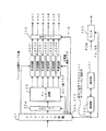
図1は第1の例の伝送形態として、マルチチャネルを圧縮するとともに再生側
のダウンミクスを禁止する場合を示している。符号化側の6チャネル(ch)ミク
ス&マトリクス回路1’は、マルチチャネル信号の一例としてフロントレフト(
Lf)、センタ(C)、フロントライト(Rf)、サラウンドレフト(Ls)、
サラウンドライト(Rs)及びLfe(Low Frequency Effect)の6chのPCM
データを次式(1−1)により6ch「1」〜「6」分の相関信号に変換し、符号
化部2’に出力する。
「1」=Lf+Rf−C
「2」=Lf−Rf−C
「3」=C−(Ls+Rs)/2
「4」=Ls+Rs
「5」=Ls−Rs
「6」=Lfe−a×C
ただし、0≦a≦1 …(1−1)
このような6チャネル(ch)ミクス&マトリクス回路1’による相関式と符
号化部2’の符号化方式は選択手段7’で選択される。以下説明する図2、図3
、図4、図5及び図6でも同様であるので、これらの図では選択手段7’を略す
ことにする。
FIG. 1 shows a case where a multi-channel is compressed and playback side downmixing is prohibited as a transmission form of the first example. The 6-channel (ch) mix & matrix circuit 1 'on the encoding side is a front left (an example of a multi-channel signal).
Lf), center (C), front right (Rf), surround left (Ls),
6ch PCM with surround light (Rs) and Lfe (Low Frequency Effect)
The data is converted into correlation signals for 6ch “1” to “6” by the following equation (1-1), and output to the
“1” = Lf + Rf−C
“2” = Lf−Rf−C
“3” = C− (Ls + Rs) / 2
“4” = Ls + Rs
“5” = Ls−Rs
“6” = Lfe−a × C
However, 0 ≦ a ≦ 1 (1-1)
The correlation equation by the 6-channel (ch) mix &
4, 5 and 6, the selection means 7 ′ is omitted in these drawings.
第1と第2の符号化部2’−1、2’−2を有する符号化部2’は図7に詳し
く示すようにこの6ch「1」〜「6」のPCMデータを予測符号化し、予測符号
化データを図8に示すようなビットストリームで記録媒体5や通信媒体6を介し
て復号側に伝送する。復号側では第1と第2の復号化部3’−1、3’−2を有
する復号化部3’により、図14に詳しく示すように6ch「1」〜「6」の予測
符号化データをPCMデータに復号し、次いでミクス&マトリクス回路4’によ
り式(1−1)に基づいて元の6ch(Lf、C、Rf、Ls、Rs、Lfe)の
みを復元する。
The
図2は第2の例の伝送形態として、マルチチャネルを圧縮するとともに再生側
のダウンミクスを許可する場合を示している。符号化側の6chミクス&マトリク
ス回路1’は、元の6ch(Lf、C、Rf、Ls、Rs、Lfe)と係数mij(
i=1,2,j=1,2〜6)により次式(2)のようにステレオ2chデータ(
L、R)を生成(ダウンミクス)する。
L=m11・Lf+m12・Rf+m13・C
+m14・Ls+m15・Rs+m16・Lfe
R=m21・Lf+m22・Rf+m23・C
+m24・Ls+m25・Rs+m26・Lfe …(2)
FIG. 2 shows a case where the multi-channel is compressed and down-mixing on the reproduction side is permitted as a transmission form of the second example. The 6-channel mix &
i = 1, 2, j = 1, 2 to 6), the stereo 2ch data (
L, R) is generated (downmixed).
L = m11 ・ Lf + m12 ・ Rf + m13 ・ C
+ M14 ・ Ls + m15 ・ Rs + m16 ・ Lfe
R = m21 ・ Lf + m22 ・ Rf + m23 ・ C
+ M24 · Ls + m25 · Rs + m26 · Lfe (2)
そして、式(2)と次式(1−2)により次のような第1グループの2チャネ
ル分の相関信号「1」、「2」と第2グループの4チャネル分の相関信号「3」
〜「6」に変換し、それぞれ第1符号化部2’−1、第2符号化部2’−2に出
力する。
「1」=L+R
「2」=L−R
「3」〜「6」は式(1−1)と同じ …(1−2)
Then, the correlation signals “1” and “2” for the two channels of the first group and the correlation signals “3” for the four channels of the second group as shown below by the equation (2) and the following equation (1-2):
To “6” and output to the
“1” = L + R
“2” = LR
“3” to “6” are the same as in formula (1-1) (1-2)
第1、第2符号化部2’−1、2’−2はそれぞれ第1グループチャネル「1
」、「2」と第2グループチャネル「3」〜「6」のPCMデータを予測符号化
し、各チャネルの予測符号化データを記録媒体5や通信媒体6を介して復号側に
伝送する。復号側では第1、第2復号化部3’−1、3’−2により、それぞれ
第1グループチャネル「1」、「2」と第2グループチャネル「3」〜「6」の
予測符号化データをPCMデータに復号し、次いでミクス&マトリクス回路4’
により式(1−2)、(2)に基づいて元の6ch(Lf、C、Rf、Ls、Rs
、Lfe)を復元するとともに、第1グループチャネル「1」、「2」を加算、
減算することによりそれぞれステレオ2chデータ(L、R)を生成する。
The first and
”,“ 2 ”and PCM data of the second group channels“ 3 ”to“ 6 ”are predictively encoded, and the predictive encoded data of each channel is transmitted to the decoding side via the
Based on the equations (1-2) and (2), the original 6ch (Lf, C, Rf, Ls, Rs
, Lfe) and the first group channels “1” and “2” are added,
Stereo 2ch data (L, R) is generated by subtraction.
図3は第3の例の伝送形態として、マルチチャネルを圧縮しないで伝送すると
ともに再生側のダウンミクスを禁止する場合を示している。この場合には、非圧
縮であるので、符号化側では相関信号も生成することなく元の6ch(Lf、C、
Rf、Ls、Rs、Lfe)のPCMデータをそのまま伝送し(ただし、フォー
マット化する)、復号化側ではデフォーマット化した後、元の6ch(Lf、C、
Rf、Ls、Rs、Lfe)のみを復元する。
FIG. 3 shows a case where the multi-channel is transmitted without compression and the reproduction side down-mixing is prohibited as a third example of transmission form. In this case, since there is no compression, the encoding side does not generate a correlation signal, and the original 6ch (Lf, C,
Rf, Ls, Rs, Lfe) PCM data is transmitted as it is (however, it is formatted), and after decoding on the decoding side, the original 6ch (Lf, C,
Rf, Ls, Rs, Lfe) only.
図4は第4の例の伝送形態として、マルチチャネルを圧縮しないで伝送すると
ともに再生側のダウンミクスを許可する場合を示している。この場合にも、非圧
縮であるので、符号化側では圧縮率を高めるための相関信号も生成することなく
元の6ch(Lf、C、Rf、Ls、Rs、Lfe)のPCMデータをそのまま伝
送する(ただし、フォーマット化する)。復号化側ではデフォーマット化した後
、元の6ch(Lf、C、Rf、Ls、Rs、Lfe)を復元するとともに、式(
2)によりステレオ2chデータ(L、R)を生成(ダウンミクス)する。
FIG. 4 shows a transmission example of the fourth example in which multi-channel transmission is performed without compression and down-mixing on the reproduction side is permitted. Also in this case, since the data is not compressed, the encoding side transmits the original 6ch (Lf, C, Rf, Ls, Rs, Lfe) PCM data without generating a correlation signal for increasing the compression rate. (But format). On the decoding side, after deformatting, the original 6ch (Lf, C, Rf, Ls, Rs, Lfe) is restored and the expression (
The stereo 2ch data (L, R) is generated (downmixed) by 2).
図5は図1においてマルチチャネルを圧縮するとともに再生側のダウンミクス
を禁止する場合の変形例を示している。この場合には、符号化側では次式(1−
3)により6ch(1)〜(6)分の相関信号に変換し、符号化部2’はこれを予
測符号化する。そして、復号化側では式(1−2)により元の6ch(Lf、C、
Rf、Ls、Rs、Lfe)のみを復元する。
「1」=Lf−C
「2」=Rf−C
「3」〜「6」は式(1−1)と同じ …(1−3)
このように再生側のダウンミクスを禁止する場合は、これに対応して式(2)の
ダウンミクス係数を符号化に加えないとともに、符号化側で式(2)によりステ
レオ2chデータ(L、R)を生成(ダウンミクス)することが禁じられる。
FIG. 5 shows a modification in the case where the multi-channel is compressed in FIG. 1 and down-mixing on the reproduction side is prohibited. In this case, on the encoding side, the following equation (1-
3) is converted into correlation signals for 6ch (1) to (6), and the
Rf, Ls, Rs, Lfe) only.
“1” = Lf−C
“2” = Rf−C
“3” to “6” are the same as in formula (1-1) (1-3)
Thus, when the reproduction side down-mixing is prohibited, the down-mix coefficient of the equation (2) is not added to the encoding correspondingly, and the stereo 2ch data (L, It is forbidden to generate (downmix) R).
図6は図2においてマルチチャネルを圧縮するとともに再生側のダウンミクス
を許可する場合の変形例を示している。この場合には、符号化側では式(2)に
よりステレオ2chデータ(L、R)を生成(ダウンミクス)し、次いで次式(1
−4)により次のような第1グループの2チャネル「1」、「2」と第2グルー
プの4チャネル分の相関信号「3」〜「6」に変換し、第1、第2符号化部2’
−1、2’−2はこの各グループチャネルを予測符号化する。そして、復号化側
では式(1−4)、(2)により元の6ch(Lf、C、Rf、Ls、Rs、Lf
e)を復元するとともにステレオ2chデータ(L、R)をそのまま出力する。
「1」=L
「2」=R
「3」〜「6」は式(1−1)と同じ …(1−4)
FIG. 6 shows a modification in the case of compressing the multi-channel in FIG. 2 and allowing down-mixing on the reproduction side. In this case, on the encoding side, stereo 2ch data (L, R) is generated (downmixed) by equation (2), and then the following equation (1)
-4) is converted into correlation signals “3” to “6” for the two channels “1” and “2” of the first group and the four channels of the second group as follows, and the first and second encodings are performed.
-1 and 2'-2 predictively encode each group channel. Then, on the decoding side, the original 6ch (Lf, C, Rf, Ls, Rs, Lf are obtained by the equations (1-4) and (2).
e) is restored and stereo 2ch data (L, R) is output as it is.
“1” = L
“2” = R
“3” to “6” are the same as in formula (1-1) (1-4)
図7を参照して符号化部2’−1、2’−2について詳しく説明する。各ch「1
」〜「6」のPCMデータは1フレーム毎に1フレームバッファ10に格納され
る。そして、1フレームの各ch「1」〜「6」のサンプルデータがそれぞれ予測
回路13D1、13D2、15D1〜15D4に印加されるとともに、各ch「1
」〜「6」の各フレームの先頭サンプルデータがフォーマット化回路19に印加
される。予測回路13D1、13D2、15D1〜15D4はそれぞれ、各ch「
1」〜「6」のPCMデータに対して、特性が異なる複数の予測器(不図示)に
より時間領域における過去の信号から現在の信号の複数の線形予測値を算出し、
次いで原PCMデータと、この複数の線形予測値から予測器毎の予測残差を算出
する。続くバッファ・選択器14D1、14D2、16D1〜16D4はそれぞ
れ、予測回路13D1、13D2、15D1〜15D4により算出された各予測
残差を一時記憶して、選択信号/DTS(デコーディング・タイム・スタンプ)
生成器17により指定されたサブフレーム毎に予測残差の最小値を選択する。
The
The PCM data of “6” to “6” are stored in the 1-
The first sample data of each frame from “6” to “6” is applied to the
For the PCM data of “1” to “6”, a plurality of linear prediction values of the current signal are calculated from past signals in the time domain by a plurality of predictors (not shown) having different characteristics,
Next, a prediction residual for each predictor is calculated from the original PCM data and the plurality of linear prediction values. The subsequent buffer / selectors 14D1, 14D2, 16D1 to 16D4 temporarily store the prediction residuals calculated by the prediction circuits 13D1, 13D2, and 15D1 to 15D4, respectively, and select signals / DTS (decoding time stamps).
The minimum value of the prediction residual is selected for each subframe designated by the
選択信号/DTS生成器17は予測残差のビット数フラグをパッキング回路1
8とフォーマット化回路19に対して印加し、また、予測残差が最小の予測器を
示す予測器選択フラグと、相関係数aと、復号化側が入力バッファ22a(図1
4)からストリームデータを取り出す時間を示すDTSをフォーマット化回路1
9に対して印加する。パッキング回路18はバッファ・選択器14D1、14D
2、16D1〜16D4により選択された6ch分の予測残差を、選択信号/DT
S生成器17により指定されたビット数フラグに基づいて指定ビット数でパッキ
ングする。またPTS生成器17cは、復号化側が出力バッファ110(図14
)からPCMデータを取り出す時間を示すPTS(プレゼンテーション・タイム
・スタンプ)を生成してフォーマット化回路19に出力する。フォーマット化回
路19にはまた、圧縮/非圧縮などを示す符号化モードと、ダウンミクス許可/
禁止を示す識別子が印加される。
The selection signal /
8 and the
4) DTS indicating the time to extract stream data from 4)
9 is applied. The
2, the prediction residual for 6ch selected by 16D1 to 16D4 is selected as a selection signal / DT
Packing is performed with the designated number of bits based on the bit number flag designated by the
PTS (Presentation Time Stamp) indicating the time for extracting the PCM data from) is generated and output to the
An identifier indicating prohibition is applied.
続くフォーマット化回路19は図8〜図13に示すようなユーザデータにフォ
ーマット化する。図8に示すユーザデータ(サブパケット)は、前方グループに
関する2ch「1」、「2」の予測符号化データを含む可変レートビットストリー
ム(サブストリーム)BS0と、他のグループに関する4ch「3」〜「6」の予
測符号化データを含む可変レートビットストリーム(サブストリーム)BS1と
、サブストリームBS0、BS1の前に設けられたビットストリームヘッダ(リ
スタートヘッダ)により構成されている。
The
また、サブストリームBS0、BS1の1フレーム分は
・フレームヘッダと、
・各ch「1」〜「6」の1フレームの先頭サンプルデータと、
・各ch「1」〜「6」のサブフレーム毎の予測器選択フラグと、
・各ch「1」〜「6」のサブフレーム毎のビット数フラグと、
・各ch「1」〜「6」の予測残差データ列(可変ビット数)と、
・ch「6」の係数aとが、
多重化されている。このような予測符号化によれば、原信号が例えばサンプリ
ング周波数=96kHz、量子化ビット数=24ビット、6チャネルの場合、7
1%の圧縮率を実現することができる。
Also, one frame of substream BS0, BS1 is a frame header,
・ First sample data of one frame of each channel “1” to “6”,
A predictor selection flag for each subframe of each channel “1” to “6”;
A bit number flag for each subframe of each channel “1” to “6”;
-Predictive residual data string (number of variable bits) of each ch "1" to "6",
The coefficient a of ch “6” is
Multiplexed. According to such predictive coding, when the original signal is, for example, sampling frequency = 96 kHz, quantization bit number = 24 bits, 6 channels, 7
A compression rate of 1% can be realized.
図7に示す符号化部2’−1、2’−2により予測符号化された可変レートビ
ットストリームデータを、記録媒体の一例としてDVDオーディオディスクに記
録する場合には、図9に示すオーディオ(A)パックにパッキングされる。この
パックは2034バイトのユーザデータ(Aパケット、Vパケット)に対して4
バイトのパックスタート情報と、6バイトのSCR(System Clock Reference:
システム時刻基準参照値)情報と、3バイトのMux レート(rate)情報と1バイ
トのスタッフィングの合計14バイトのパックヘッダが付加されて構成されてい
る(1パック=合計2048バイト)。この場合、タイムスタンプであるSCR
情報を、先頭パックでは「1」として同一タイトル内で連続とすることにより同
一タイトル内のAパックの時間を管理することができる。
When the variable rate bit stream data predictively encoded by the
Byte pack start information and 6 byte SCR (System Clock Reference:
A system time base reference value) information, a 3-byte Mux rate information, and a 1-byte stuffing total 14-byte pack header are added (1 pack = total 2048 bytes). In this case, the time stamp SCR
By making the information continuous in the same title as “1” in the first pack, the time of the A pack in the same title can be managed.
圧縮PCMのAパケットは図10に詳しく示すように、19又は14バイトの
パケットヘッダと、圧縮PCMのプライベートヘッダと、図11に示すフォーマ
ットの1ないし2011バイトのオーディオデータ(圧縮PCM)により構成さ
れている。そして、DTSとPTSは図5のパケットヘッダ内に(具体的にはパ
ケットヘッダの10〜14バイト目にPTSが、15〜19バイト目にDTSが
)セットされる。圧縮PCMのプライベートヘッダは、
・1バイトのサブストリームIDと、
・2バイトのUPC/EAN−ISRC(Universal Product Code/European Ar
ticle Number-International Standard Recording Code)番号、及びUPC/E
AN−ISRCデータと、
・1バイトのプライベートヘッダ長と、
・2バイトの第1アクセスユニットポインタと、
・8バイトのオーディオデータ情報(ADI)と、
・0〜7バイトのスタッフィングバイトとに、
より構成されている。
As shown in FIG. 10, the compressed PCM A packet is composed of a 19 or 14 byte packet header, a compressed PCM private header, and 1 to 2011 byte audio data (compressed PCM) in the format shown in FIG. ing. The DTS and PTS are set in the packet header of FIG. 5 (specifically, the PTS is in the 10th to 14th bytes of the packet header and the DTS is in the 15th to 19th bytes). The compressed PCM private header is
A 1-byte substream ID,
・ 2-byte UPC / EAN-ISRC (Universal Product Code / European Ar
ticle Number-International Standard Recording Code) number and UPC / E
AN-ISRC data,
-1 byte private header length,
A 2-byte first access unit pointer;
8 bytes of audio data information (ADI)
・ With stuffing byte of 0-7 bytes,
It is made up of.
また、ADI内に1秒後のアクセスユニットをサーチするための前方アクセス
ユニット・サーチポインタと、1秒前のアクセスユニットをサーチするための後
方アクセスユニット・サーチポインタがともに1バイトでセットされる。具体的
にはADIの7バイト目に前方アクセスユニット・サーチポインタが、8バイト
目に後方アクセスユニット・サーチポインタがセットされる。
In addition, a front access unit search pointer for searching for an access unit after one second and a rear access unit search pointer for searching for an access unit one second before are both set in one byte in the ADI. Specifically, the forward access unit / search pointer is set in the seventh byte of the ADI, and the backward access unit / search pointer is set in the eighth byte.
図10に示す圧縮PCM(PPCMともいう)のオーディオパケットにおける
オーディオデータエリアは、図11に示すようにサブパケットと複数のPPCM
アクセスユニットにより構成され、PPCMアクセスユニットはPPCMシンク
情報とサブパケットにより構成されている。最初のPPCMアクセスユニット内
のサブパケットは、ディレクトリと、サブストリーム「0」と、CRCと、サブ
ストリーム「1」と、CRCとエクストラ情報により構成され、サブストリーム
「0」、「1」はPPCMブロックのみにより構成されている。2番目以降のP
PCMアクセスユニット内のサブパケットは、ディレクトリを除いてサブストリ
ーム「0」と、CRCと、サブストリーム「1」と、CRCとエクストラ情報に
より構成され、サブストリーム「0」、「1」はリスタートヘッダとPPCMブ
ロックにより構成されている。
The audio data area in the audio packet of the compressed PCM (also referred to as PPCM) shown in FIG. 10 includes a sub-packet and a plurality of PPCMs as shown in FIG.
The PPCM access unit is composed of PPCM sync information and subpackets. The subpacket in the first PPCM access unit is composed of a directory, a substream “0”, a CRC, a substream “1”, a CRC, and extra information. The substreams “0” and “1” are PPCM. It consists only of blocks. P after the second
The subpacket in the PCM access unit is composed of substream “0”, CRC, substream “1”, CRC and extra information except for the directory, and substreams “0” and “1” are restarted. It consists of a header and a PPCM block.
PPCMシンク情報(以下、同期情報ともいう)は次の情報を含む。
・1パケット当たりのサンプル数:サンプリング周波数fsに応じて40、80
又は160が選択される。
・データレート:VBRの場合には「0」(サブパケット内のデータが圧縮デー
タであることを示す識別子)
・サンプリング周波数fs及び量子化ビット数Qb
・チャネル割り当て情報
The PPCM sync information (hereinafter also referred to as synchronization information) includes the following information.
-Number of samples per packet: 40, 80 depending on the sampling frequency fs
Or 160 is selected.
Data rate: “0” in the case of VBR (an identifier indicating that the data in the subpacket is compressed data)
-Sampling frequency fs and number of quantization bits Qb
・ Channel allocation information
フォーマット化回路19はまた、図8〜図11に示すオーディオパックを管理
するために図12、図13に示すような管理情報を含むATSI(オーディオ・
タイトル・セット・インフォーメーション)をフォーマット化する。図12はA
OTT−AOB−ATR(オーディオオンリタイトル・オーディオオブジェクト
セット・アトリビュート)を示し、このAOTT−AOB−ATR(b127〜
b0)は、MSB側から順に
・8ビット(b127〜b120)のオーディオ符号化モードと、
・8ビット(b119〜b112)の保留領域と、
・4ビット(b111〜b108)のチャネルグループ「1」の量子化ビット数
Q1と、
・4ビット(b107〜b104)のチャネルグループ「2」の量子化ビット数
Q2と、
・4ビット(b103〜b100)のチャネルグループ「1」のサンプリング周
波数fs1と、
・4ビット(b99〜b96)のチャネルグループ「2」のサンプリング周波数
fs2と、
・3ビット(b95〜b93)のマルチチャネル構造のタイプと、
・5ビット(b92〜b88)のチャネル割り当てと、
・8ビット×11(b87〜b0)の保留領域により構成されている。
The
(Title Set Information). FIG.
OTT-AOB-ATR (audio only title / audio object set attribute) is indicated, and this AOTT-AOB-ATR (b127-
b0) is an audio encoding mode of 8 bits (b127 to b120) in order from the MSB side;
An 8-bit (b119 to b112) reserved area;
A quantization bit number Q1 of a channel group “1” of 4 bits (b111 to b108);
A quantization bit number Q2 of a channel group “2” of 4 bits (b107 to b104);
A sampling frequency fs1 of a channel group “1” of 4 bits (b103 to b100);
A sampling frequency fs2 of a 4-bit (b99 to b96) channel group “2”;
3 bit (b95 to b93) multi-channel structure type;
-Channel assignment of 5 bits (b92 to b88);
-It is composed of a reserved area of 8 bits x 11 (b87 to b0).
上記データを以下に詳しく示す。
(1)オーディオ符号化モード(b127〜b120)
00000000b:リニアPCMモード
00000001b:圧縮PCMモード
その他 :その他の符号化モード用に保留
The above data is shown in detail below.
(1) Audio encoding mode (b127 to b120)
00000000b: Linear PCM mode 00000001b: Compressed PCM mode Others: Reserved for other encoding modes
(2)チャネルグループ1の量子化ビット数Q1(b111〜b108)
0000b:16ビット
0001b:20ビット
0010b:24ビット
その他 :保留
(3)チャネルグループ2の量子化ビット数Q2(b107〜b104)
・チャネルグループ1の量子化ビット数Q1が「0000b」の場合には「0
000b」
・チャネルグループ1の量子化ビット数Q1が「0001b」の場合には「0
000b」又は「0001b」
・チャネルグループ1の量子化ビット数Q1が「0010b」の場合には「0
000b」、「0001b」又は「0010b」
ただし、0000b:16ビット
0001b:20ビット
0010b:24ビット
その他 :保留
(2) Quantization bit number Q1 (b111 to b108) of
0000b: 16 bits 0001b: 20 bits 0010b: 24 bits Others: Reserved (3) Quantization bit number Q2 of channel group 2 (b107 to b104)
When the quantization bit number Q1 of the
000b "
When the quantization bit number Q1 of the
000b "or" 0001b "
When the quantization bit number Q1 of the
000b "," 0001b "or" 0010b "
However, 0000b: 16 bits
0001b: 20 bits
0010b: 24 bits
Other: Hold
(4)チャネルグループ1のサンプリング周波数fs1(b103〜b100)
0000b:48kHz
0001b:96kHz
0010b:192kHz
1000b:44.1kHz
1001b:88.2kHz
1010b:176.4kHz
その他 :保留
(4) Sampling frequency fs1 (b103 to b100) of
0000b: 48 kHz
0001b: 96 kHz
0010b: 192 kHz
1000b: 44.1 kHz
1001b: 88.2 kHz
1010b: 176.4 kHz
Other: Hold
(5)チャネルグループ2のサンプリング周波数fs2(b99〜b96)
・チャネルグループ1のサンプリング周波数fs1が「0000b」の場合に
は「0000b」
・チャネルグループ1のサンプリング周波数fs1が「0001b」の場合に
は「0000b」又は「0001b」
・チャネルグループ1のサンプリング周波数fs1が「0010b」の場合に
は「0000b」、「0001b」又は「0010b」
・チャネルグループ1のサンプリング周波数fs1が「1000b」の場合に
は「1000b」
・チャネルグループ1のサンプリング周波数fs1が「1001b」の場合に
は「1000b」又は「1001b」
・チャネルグループ1のサンプリング周波数fs1が「1010b」の場合に
は「1000b」、「1001b」又は「1010b」
(5) Sampling frequency fs2 of channel group 2 (b99 to b96)
“0000b” when the sampling frequency fs1 of
When the sampling frequency fs1 of the
When the sampling frequency fs1 of the
“1000b” when the sampling frequency fs1 of
When the sampling frequency fs1 of the
When the sampling frequency fs1 of the
(6)マルチチャネル構造のタイプ(b95〜b93)
000b:タイプ1
その他 :保留
(7)チャネル割り当て(b92〜b88)
1チャネル(モノラル)から6チャネルまでのグループ「1」、「2」のチャ
ネル割り当て情報
(6) Type of multi-channel structure (b95 to b93)
000b:
Other: Reserved (7) Channel allocation (b92 to b88)
Channel assignment information for groups “1” and “2” from 1 channel (monaural) to 6 channels
図13はATS−PG−CNT(オーディオタイトルセット・プログラム・コ
ンテンツ)を示し、これは先頭から順に
・1ビット(b31)の、前回と今回のPGの関係(R/A)と、
・1ビット(b30)のSTC不連続性フラグ(STC−F)と、
・3ビット(b29〜b27)のアトリビュート数(ATRN)と、
・3ビット(b26〜b24)のチャネルグループ(ChGr)「2」のビット
シフトデータと、
・2ビット(b23、b22)の保留領域と、
・1ビット(b21)のダウンミックスモード(D−M)と、
・1ビット(b20)のダウンミックス係数の有効性(図示※)と、
・4ビット(b19〜b16)のダウンミックス係数テーブル番号(DM−CO
EFTN)と、
・各々が1ビット、合計16ビット(b15〜b0)のRTIフラグF15〜F
0により構成されている。
そして、ビット(b21)のダウンミクスモード(D−M)が「1」の場合に
「ダウンミクス禁止」、「0」の場合に「ダウンミクス許可」を表す。
FIG. 13 shows ATS-PG-CNT (audio title set / program / content), which is, in order from the top, 1 bit (b31), the relationship between the previous and current PG (R / A),
1-bit (b30) STC discontinuity flag (STC-F);
・ The number of attributes (ATRN) of 3 bits (b29 to b27),
3 bit (b26 to b24) channel group (ChGr) “2” bit shift data;
A 2-bit (b23, b22) reserved area;
1-bit (b21) downmix mode (D-M),
・ Effectiveness of 1-bit (b20) downmix coefficient (shown *),
-4-bit (b19 to b16) downmix coefficient table number (DM-CO
EFTN)
・ Each RTI flags F15 to F of 1 bit each and 16 bits in total (b15 to b0)
0 is configured.
When the downmix mode (DM) of the bit (b21) is “1”, “downmix prohibition” is indicated, and when it is “0”, “downmix permission” is indicated.
次に図14を参照して復号化部3’(3’−1、3’−2)について説明する
。なお、この復号化部3’(3’−1、3’−2)とミクス&マトリクス回路4
’は、ハードウエアの他にコンピュータプログラムよっても実現することができ
る。上記フォーマットの可変レートビットストリームデータBS0、BS1は、
デフォーマット化回路21により分離される。そして、各ch「1」〜「6」の
1フレームの先頭サンプルデータと予測器選択フラグはそれぞれ予測回路24D
1、24D2、23D1〜23D4に印加され、各ch「1」〜「6」のビット
数フラグはアンパッキング回路22に印加される。また、SCRと、DTSと予
測残差データ列は入力バッファ22aに印加され、PTSは出力バッファ110
に印加される。また、圧縮/非圧縮などを示す符号化モードと、ダウンミクス許
可/禁止を示す識別子は制御部100に印加され、サンプリング周波数fs及び
量子化ビット数QbはD/A変換器102に印加される。ここで、予測回路24
D1、24D2、23D1〜23D4内の複数の予測器(不図示)はそれぞれ、
符号化側の予測回路13D1、13D2、15D1〜15D4内の複数の予測器
と同一の特性であり、予測器選択フラグにより同一特性のものが選択される。
Next, the
'Can also be realized by a computer program in addition to hardware. The variable rate bit stream data BS0, BS1 of the above format is
They are separated by the deformatting circuit 21. Then, the first sample data of one frame of each channel “1” to “6” and the predictor selection flag are set in the prediction circuit 24D
1, 24D2, 23D1 to 23D4, and the bit number flags of each channel “1” to “6” are applied to the unpacking
To be applied. An encoding mode indicating compression / non-compression and an identifier indicating permission / prohibition of downmixing are applied to the
A plurality of predictors (not shown) in D1, 24D2, 23D1 to 23D4 are respectively
The same characteristics as those of the plurality of predictors in the encoding-side prediction circuits 13D1, 13D2, and 15D1 to 15D4, and the same characteristics are selected by the predictor selection flag.
デフォーマット化回路21により分離されたストリームデータ(予測残差デー
タ列)は、図15に示すようにSCRによりアクセスユニット毎に入力バッファ
22aに取り込まれて蓄積される。ここで、1つのアクセスユニットのデータ量
は、例えばfs=96kHzの場合には(1/96kHz)秒分であるが、図1
6、図17(a)に詳しく示すように可変長である。そして、入力バッファ22
aに蓄積されたストリームデータはDTSに基づいてFIFOで読み出されてア
ンパッキング回路22に印加される。
The stream data (predictive residual data string) separated by the deformatting circuit 21 is taken in and stored in the input buffer 22a for each access unit by the SCR as shown in FIG. Here, the data amount of one access unit is, for example, (1/96 kHz) seconds when fs = 96 kHz.
6. Variable length as shown in detail in FIG. The
The stream data stored in a is read out by the FIFO based on the DTS and applied to the unpacking
アンパッキング回路22は各ch「1」〜「6」の予測残差データ列をビット
数フラグ毎に基づいて分離してそれぞれ予測回路24D1、24D2、23D1
〜23D4に出力する。予測回路24D1、24D2、23D1〜23D4では
それぞれ、アンパッキング回路22からの各ch「1」〜「6」の今回の予測残
差データと、内部の複数の予測器の内、予測器選択フラグにより選択された各1
つにより予測された前回の予測値が加算されて今回の予測値が算出され、次いで
1フレームの先頭サンプルデータを基準として各サンプルのPCMデータが算出
されて出力バッファ110に蓄積される。出力バッファ110に蓄積されたPC
MデータはPTSに基づいて読み出されて出力され、したがって、図17(a)
に示す可変長のアクセスユニットが伸長されて、図17(b)に示す一定長のプ
レゼンテーションユニットが出力される。
The unpacking
To 23D4. Each of the prediction circuits 24D1, 24D2, 23D1 to 23D4 uses the current prediction residual data of each channel “1” to “6” from the unpacking
The previous predicted value predicted by the two is added to calculate the current predicted value, and then the PCM data of each sample is calculated and stored in the
The M data is read out and output based on the PTS, and accordingly, FIG.
The variable-length access unit shown in FIG. 17 is expanded to output a fixed-length presentation unit shown in FIG.
また、PPCMシンク情報内のサンプリング周波数fs及び量子化ビット数Q
bに基づいて、PCMデータがD/A変換器102によりアナログ信号に変換さ
れる。ここで、操作部101を介してサーチ再生が指示された場合には、制御部
100により図5に示す前方アクセスユニット・サーチポインタ(1秒先)と後
方アクセスユニット・サーチポインタ(1秒前)に基づいてアクセスユニットを
再生する。このサーチポインタとしては、1秒先、1秒前の代わりに2秒先、2
秒前のものでよい。
Also, the sampling frequency fs and the quantization bit number Q in the PPCM sync information
Based on b, the PCM data is converted into an analog signal by the D /
The one a second ago may be used.
符号化部2’(2’−1、2’−2)により予測符号化された可変レートビッ
トストリームデータをネットワークを介して伝送する場合には、符号化側では図
18に示すように伝送用にパケット化し(ステップS41)、次いでパケットヘ
ッダを付与し(ステップS42)、次いでこのパケットをネットワーク上に送り
出す(ステップS43)。
When the variable rate bit stream data that has been predictively encoded by the
復号側では図19(A)に示すようにヘッダを除去し(ステップS51)、次
いでデータを復元し(ステップS52)、次いでこのデータをメモリに格納して
復号を待つ(ステップS53)。そして、復号を行う場合には図19(B)に示
すように、デフォーマット化を行い(ステップS61)、次いで入力バッファ2
2aの入出力制御を行い(ステップS62)、次いでアンパッキングを行う(ス
テップS63)。なお、このとき、サーチ再生指示がある場合にはサーチポイン
タをデコードする。次いで予測器をフラグに基づいて選択してデコードを行い(
ステップS64)、次いで出力バッファ110の入出力制御を行い(ステップS
65)、次いで元のマルチチャネルを復元し(ステップS66)、次いでこれを
出力し(ステップS67)、以下、これを繰り返す。
As shown in FIG. 19A, the decoding side removes the header (step S51), then restores the data (step S52), then stores this data in the memory and waits for decoding (step S53). When decoding is performed, as shown in FIG. 19B, deformatting is performed (step S61), and then the
Input / output control of 2a is performed (step S62), and then unpacking is performed (step S63). At this time, if there is a search reproduction instruction, the search pointer is decoded. The predictor is then selected based on the flag and decoded (
Next, input / output control of the
65) Next, the original multi-channel is restored (step S66), then this is output (step S67), and this is repeated thereafter.
次に図20、図21を参照して第2の実施形態について説明する。上記の実施
形態では、1グループの相関性の信号「1」〜「6」を予測符号化するように構
成されているが、この第4の実施形態では複数グループの相関性のある信号を生
成して予測符号化し、圧縮率が最も高いグループの予測符号化データを選択する
ように構成されている。このため図20に示す符号化部では、第1〜第nの相関
回路1−1〜1−nが設けられ、このn個の相関回路1−1〜1−nは例えば6
ch(Lf、C、Rf、Ls、Rs、Lfe)のPCMデータを、相関性が異なる
n種類の6ch信号「1」〜「6」に変換する。
Next, a second embodiment will be described with reference to FIGS. In the above embodiment, a group of correlated signals “1” to “6” is configured to be predictively encoded. In the fourth embodiment, a plurality of groups of correlated signals are generated. Thus, the prediction coding is performed, and the prediction coding data of the group having the highest compression rate is selected. For this reason, the encoding unit shown in FIG. 20 includes first to nth correlation circuits 1-1 to 1-n, and the n correlation circuits 1-1 to 1-n are, for example, 6
The PCM data of ch (Lf, C, Rf, Ls, Rs, Lfe) is converted into n types of 6ch signals “1” to “6” having different correlations.
例えば第1の相関回路1−1は以下のように変換し、
(1)=Lf
(2)=C−(Ls+Rs)/2
(3)=Rf−Lf
(4)=Ls−a×Lfe
(5)=Rs−b×Rf
(6)=Lfe
また、第nの相関回路1−nは以下のように変換する。
(1)=Lf+Rf
(2)=C−Lf
(3)=Rf−Lf
(4)=Ls−Lf
(5)=Rs−Lf
(6)=Lfe−C
For example, the first correlation circuit 1-1 converts as follows:
(1) = Lf
(2) = C− (Ls + Rs) / 2
(3) = Rf−Lf
(4) = Ls−a × Lfe
(5) = Rs−b × Rf
(6) = Lfe
The n-th correlation circuit 1-n converts as follows.
(1) = Lf + Rf
(2) = C-Lf
(3) = Rf−Lf
(4) = Ls−Lf
(5) = Rs−Lf
(6) = Lfe-C
また、相関回路1−1〜1−n毎に予測回路15とバッファ・選択器16が設
けられ、グループ毎の予測残差の最小値のデータ量に基づいて圧縮率が最も高い
グループが相関選択信号生成器17bにより選択される。このとき、フォーマッ
ト化回路19はその選択フラグ(相関回路選択フラグ、その相関回路の相関係数
a、b)を追加して多重化する。
Further, a
また、図21に示す復号化側では、符号化側の相関回路1−1〜1−nに対し
てn個の相関回路4−1〜4−n(又は係数a、bが変更可能な1つの相関回路
4)が設けられる。なお、図20に示すnグループの予測回路が同一の構成であ
る場合、復号装置では図21に示すようにnグループ分の予測回路を設ける必要
はなく、1つのグループ分の予測回路でよい。そして、符号化装置から伝送され
た選択フラグに基づいて相関回路4−1〜4−nの1つを選択、又は係数a、b
を設定して元の6ch(Lf、C、Rf、Ls、Rs、Lfe)を復元し、また、
式(2)によりマルチチャネルをダウンミクスしてステレオ2chデータ(L、R
)を生成する。
Further, on the decoding side shown in FIG. 21, n correlation circuits 4-1 to 4-n (or coefficients a and b can be changed to 1 with respect to the correlation circuits 1-1 to 1-n on the encoding side. Two correlation circuits 4) are provided. When the n groups of prediction circuits shown in FIG. 20 have the same configuration, the decoding device does not need to have n groups of prediction circuits as shown in FIG. 21, and only one group of prediction circuits may be used. Then, one of the correlation circuits 4-1 to 4-n is selected based on the selection flag transmitted from the encoding device, or the coefficients a and b
To restore the original 6ch (Lf, C, Rf, Ls, Rs, Lfe),
Stereo 2ch data (L, R
) Is generated.
また、上記の第1の実施形態では、1種類の相関性の信号「1」〜「6」を予
測符号化するように構成されているが、この信号「1」〜「6」のグループと原
信号(Lf、C、Rf、Ls、Rs、Lfe)のグループを予測符号化し、圧縮
率が高い方のグループを選択するようにしてもよい。
本発明によれば、特許請求の範囲に記載した発明の他に、次のような発明が提
供される。
マルチチャネルの音声信号が圧縮されたデータ又は圧縮されないデータを選択
的にオーディオパケットに配置するフォーマット化手段と、
前記オーディオパケット内のマルチチャネルデータが圧縮されているか否か、
あるいは、前記オーディオパケット内のマルチチャネルデータをステレオ2チャ
ネルにダウンミクスすることを許可するか又は禁止するかによってあらかじめダ
ウンミクスして符号化するか否か、あるいはダウンミクス係数を符号化するか否
かを選択する手段とを、
有する音声符号化装置。
In the first embodiment described above, one type of correlation signal “1” to “6” is configured to be predictively encoded. The group of signals “1” to “6” A group of original signals (Lf, C, Rf, Ls, Rs, Lfe) may be predictively encoded, and a group with a higher compression rate may be selected.
According to the present invention, in addition to the invention described in the claims, the following invention is provided.
Formatting means for selectively placing compressed or uncompressed data in a multi-channel audio signal in an audio packet;
Whether multi-channel data in the audio packet is compressed,
Alternatively, whether or not the multi-channel data in the audio packet is down-mixed in advance depending on whether the multi-channel data in the audio packet is allowed or prohibited to be down-mixed, or whether or not the down-mix coefficient is encoded. And a means for selecting
A speech encoding apparatus having the same.
1’ 6chミクス&マトリクス回路
13D1,13D2,15D1〜15D4 予測回路(バッファ・選択器14
D1,14D2,16D1〜16D4と共に圧縮手段を構成する。)
14D1,14D2,16D1〜16D4 バッファ・選択器
17 選択信号/DTS生成器
17c PTS生成器
19 フォーマット化回路
21 デフォーマット化回路(分離手段)
22 アンパッキング回路
22a 入力バッファ
24D1,24D2,23D1〜23D4 予測回路(伸長手段)
100 制御部(再生手段)
102 D/A変換器
110 出力バッファ
1 '6ch mix & matrix circuit 13D1, 13D2, 15D1-15D4 Prediction circuit (buffer / selector 14)
The compression means is configured together with D1, 14D2, 16D1 to 16D4. )
14D1, 14D2, 16D1 to 16D4 Buffer /
22 Unpacking circuit 22a Input buffer 24D1, 24D2, 23D1 to 23D4 Prediction circuit (expanding means)
100 Control unit (reproducing means)
102 D /
Claims (3)
SCR情報を含むパックヘッダと、圧縮PCMアクセスユニットを含むユーザデータと、を含んだデータ構造にすると共に、前記圧縮PCMアクセスユニットは、前記フレーム中に複数設けられ、前記選択されたサブフレーム毎の各チャネルの予測部を示す予測部選択情報と予測残差とを含む予測符号化データを、前記圧縮PCMアクセスユニット内に配置される前記2チャネルのダウンミクス処理チャネルを含む第1のビットストリームとその他のチャネルを含む第2のビットストリームからなるサブパケットに前記予測残差を指定されたビット情報に基づいたビット数でパッキングして格納し、さらに前記サブパケット内のデータが可変ビットレート圧縮された圧縮データであることを示すVBR識別子と、再生側において元のアナログ音声信号に復元される際に用いられるサンプリング周波数及び量子化ビット数とを含む同期情報部を設けると共に、さらに、前記先頭サンプル値を前記圧縮PCMアクセスユニット内の前記サブパケットに収納するようにした音声符号化方法により符号化されたデータを伝送する音声信号伝送装置であって、The data structure includes a pack header including SCR information and user data including a compressed PCM access unit, and a plurality of the compressed PCM access units are provided in the frame. A first bitstream including the two-channel downmix processing channels arranged in the compressed PCM access unit, and prediction encoded data including prediction unit selection information indicating a prediction unit of each channel and a prediction residual; The predicted residual is packed and stored in a sub-packet composed of a second bit stream including other channels with the number of bits based on the designated bit information, and the data in the sub-packet is compressed with a variable bit rate. VBR identifier indicating that it is compressed data and the original analog on the playback side A synchronization information part including a sampling frequency and the number of quantization bits used for restoration to a voice signal is provided, and the head sample value is stored in the subpacket in the compressed PCM access unit. An audio signal transmission apparatus for transmitting data encoded by an audio encoding method,
前記先頭サンプル値と前記選択された予測部を示す予測部選択情報と予測残差とを含む予測符号化データと前記SCR情報とをパケット化して伝送することを特徴とする音声信号伝送装置。An audio signal transmission apparatus characterized in that the encoded encoded data including the head sample value, prediction unit selection information indicating the selected prediction unit, and prediction residual and the SCR information are packetized and transmitted.
SCR情報を含むパックヘッダと、圧縮PCMアクセスユニットを含むユーザデータと、を含んだデータ構造にすると共に、前記圧縮PCMアクセスユニットは、前記フレーム中に複数設けられ、前記選択されたサブフレーム毎の各チャネルの予測部を示す予測部選択情報と予測残差とを含む予測符号化データを、前記圧縮PCMアクセスユニット内に配置される前記2チャネルのダウンミクス処理チャネルを含む第1のビットストリームとその他のチャネルを含む第2のビットストリームからなるサブパケットに前記予測残差を指定されたビット情報に基づいたビット数でパッキングして格納し、さらに前記サブパケット内のデータが可変ビットレート圧縮された圧縮データであることを示すVBR識別子と、再生側において元のアナログ音声信号に復元される際に用いられるサンプリング周波数及び量子化ビット数とを含む同期情報部を設けると共に、さらに、前記先頭サンプル値を前記圧縮PCMアクセスユニット内の前記サブパケットに収納するようにした音声符号化方法により符号化されたデータがパケット化され伝送されたパケットを受信する受信手段と、The data structure includes a pack header including SCR information and user data including a compressed PCM access unit, and a plurality of the compressed PCM access units are provided in the frame. A first bitstream including the two-channel downmix processing channels arranged in the compressed PCM access unit, and prediction encoded data including prediction unit selection information indicating a prediction unit of each channel and a prediction residual; The predicted residual is packed and stored in a sub-packet composed of a second bit stream including other channels with the number of bits based on the designated bit information, and the data in the sub-packet is compressed with a variable bit rate. VBR identifier indicating that it is compressed data and the original analog on the playback side A synchronization information part including a sampling frequency and the number of quantization bits used for restoration to a voice signal is provided, and the head sample value is stored in the subpacket in the compressed PCM access unit. Receiving means for receiving a packet in which data encoded by a voice encoding method is packetized and transmitted;
前記受信したパケットに基づき元のデータを復元する復元手段と、Restoring means for restoring original data based on the received packet;
前記復元したデータの圧縮PCMアクセスユニットをSCR情報により時間管理する時間管理手段と、Time management means for managing the compressed PCM access unit of the restored data by SCR information;
前記同期情報部からVBR識別子を抽出して、この抽出された識別子に基づいて前記サブパケットから先頭サンプル値を取り出すと共に各サブパケットから予測残差と予測部を示す予測部選択情報とを取り出し、この予測残差を前記ビット情報に基づいたビット数で復号し、この復号した予測残差と前記先頭サンプル値と前記予測部選択情報により選択される予測部とに基づいて前記サブフレーム毎に予測値を算出する手段と、Extracting a VBR identifier from the synchronization information part, taking a leading sample value from the subpacket based on the extracted identifier and taking out a prediction residual and a prediction part selection information indicating a prediction part from each subpacket, The prediction residual is decoded with the number of bits based on the bit information, and prediction is performed for each subframe based on the decoded prediction residual, the leading sample value, and a prediction unit selected by the prediction unit selection information. Means for calculating a value;
この算出された予測値から、前記2チャネルのダウンミクス処理チャネルを取得して前記ダウンミクスして得た2チャネルの音声データを復元するとともに、前記マルチチャネルの音声データを復元し、この復元した2チャネルの音声データとマルチチャネルの音声データを前記サンプリング周波数及び量子化ビット数に基づいてアナログ音声信号に変換する手段とを、From the calculated predicted value, the two-channel down-mix processing channel is acquired and the two-channel audio data obtained by the down-mixing is restored, and the multi-channel audio data is restored and restored. Means for converting 2-channel audio data and multi-channel audio data into an analog audio signal based on the sampling frequency and the number of quantization bits;
有する音声信号受信装置。An audio signal receiving apparatus.
SCR情報を含むパックヘッダと、圧縮PCMアクセスユニットを含むユーザデータと、を含んだデータ構造にすると共に、前記圧縮PCMアクセスユニットは、前記フレーム中に複数設けられ、前記選択されたサブフレーム毎の各チャネルの予測部を示す予測部選択情報と予測残差とを含む予測符号化データを、前記圧縮PCMアクセスユニット内に配置される前記2チャネルのダウンミクス処理チャネルを含む第1のビットストリームとその他のチャネルを含む第2のビットストリームからなるサブパケットに前記予測残差を指定されたビット情報に基づいたビット数でパッキングして格納し、さらに前記サブパケット内のデータが可変ビットレート圧縮された圧縮データであることを示すVBR識別子と、再生側において元のアナログ音声信号に復元される際に用いられるサンプリング周波数及び量子化ビット数とを含む同期情報部を設けると共に、さらに、前記先頭サンプル値を前記圧縮PCMアクセスユニット内の前記サブパケットに収納するようにした音声符号化方法により符号化されたデータをパケット化して伝送する音声信号伝送装置と、The data structure includes a pack header including SCR information and user data including a compressed PCM access unit, and a plurality of the compressed PCM access units are provided in the frame. A first bitstream including the two-channel downmix processing channels arranged in the compressed PCM access unit, and prediction encoded data including prediction unit selection information indicating a prediction unit of each channel and a prediction residual; The predicted residual is packed and stored in a sub-packet composed of a second bit stream including other channels with the number of bits based on the designated bit information, and the data in the sub-packet is compressed with a variable bit rate. VBR identifier indicating that it is compressed data and the original analog on the playback side A synchronization information part including a sampling frequency and the number of quantization bits used for restoration to a voice signal is provided, and the head sample value is stored in the subpacket in the compressed PCM access unit. An audio signal transmission apparatus for packetizing and transmitting data encoded by the audio encoding method;
音声信号伝送装置でパケット化され伝送されたパケットを受信する受信手段と、Receiving means for receiving packets packetized and transmitted by the audio signal transmission device;
前記受信したパケットに基づき元のデータを復元する復元手段と、Restoring means for restoring original data based on the received packet;
前記復元したデータの圧縮PCMアクセスユニットをSCR情報により時間管理する時間管理手段と、Time management means for managing the compressed PCM access unit of the restored data by SCR information;
前記同期情報部からVBR識別子を抽出して、この抽出された識別子に基づいて前記サブパケットから先頭サンプル値を取り出すと共に各サブパケットから予測残差と予測部を示す予測部選択情報とを取り出し、この予測残差を前記ビット情報に基づいたビット数で復号し、この復号した予測残差と前記先頭サンプル値と前記予測部選択情報により選択される予測部とに基づいて前記サブフレーム毎に予測値を算出する手段と、Extracting a VBR identifier from the synchronization information part, taking a leading sample value from the subpacket based on the extracted identifier and taking out a prediction residual and a prediction part selection information indicating a prediction part from each subpacket, The prediction residual is decoded with the number of bits based on the bit information, and prediction is performed for each subframe based on the decoded prediction residual, the leading sample value, and a prediction unit selected by the prediction unit selection information. Means for calculating a value;
この算出された予測値から、前記2チャネルのダウンミクス処理チャネルを取得して前記ダウンミクスして得た2チャネルの音声データを復元するとともに、前記マルチチャネルの音声データを復元し、この復元した2チャネルの音声データとマルチチャネルの音声データを前記サンプリング周波数及び量子化ビット数に基づいてアナログ音声信号に変換する手段とを、From the calculated predicted value, the two-channel down-mix processing channel is acquired and the two-channel audio data obtained by the down-mixing is restored, and the multi-channel audio data is restored and restored. Means for converting 2-channel audio data and multi-channel audio data into an analog audio signal based on the sampling frequency and the number of quantization bits;
有する音声信号受信装置と、An audio signal receiving device comprising:
からなる音声信号伝送システム。An audio signal transmission system consisting of
Priority Applications (1)
| Application Number | Priority Date | Filing Date | Title |
|---|---|---|---|
| JP2009100825A JP4983847B2 (en) | 2009-04-17 | 2009-04-17 | Audio signal transmission device, audio signal reception device, and audio signal transmission system |
Applications Claiming Priority (1)
| Application Number | Priority Date | Filing Date | Title |
|---|---|---|---|
| JP2009100825A JP4983847B2 (en) | 2009-04-17 | 2009-04-17 | Audio signal transmission device, audio signal reception device, and audio signal transmission system |
Related Parent Applications (1)
| Application Number | Title | Priority Date | Filing Date |
|---|---|---|---|
| JP2006187739A Division JP4378712B2 (en) | 2006-07-07 | 2006-07-07 | Speech encoding method and speech decoding method |
Publications (2)
| Publication Number | Publication Date |
|---|---|
| JP2009211080A JP2009211080A (en) | 2009-09-17 |
| JP4983847B2 true JP4983847B2 (en) | 2012-07-25 |
Family
ID=41184224
Family Applications (1)
| Application Number | Title | Priority Date | Filing Date |
|---|---|---|---|
| JP2009100825A Expired - Fee Related JP4983847B2 (en) | 2009-04-17 | 2009-04-17 | Audio signal transmission device, audio signal reception device, and audio signal transmission system |
Country Status (1)
| Country | Link |
|---|---|
| JP (1) | JP4983847B2 (en) |
Family Cites Families (4)
| Publication number | Priority date | Publication date | Assignee | Title |
|---|---|---|---|---|
| JPS623535A (en) * | 1985-06-28 | 1987-01-09 | Fujitsu Ltd | Encodeding transmission equipment |
| JPS6444499A (en) * | 1987-08-12 | 1989-02-16 | Fujitsu Ltd | Forecast encoding system for voice |
| JPH06133252A (en) * | 1992-10-16 | 1994-05-13 | Hitachi Ltd | Signal conversion system and signal inverse conversion system |
| JPH1064199A (en) * | 1996-04-27 | 1998-03-06 | Victor Co Of Japan Ltd | Optical disk for audio, and encoding device/decoding device |
-
2009
- 2009-04-17 JP JP2009100825A patent/JP4983847B2/en not_active Expired - Fee Related
Also Published As
| Publication number | Publication date |
|---|---|
| JP2009211080A (en) | 2009-09-17 |
Similar Documents
| Publication | Publication Date | Title |
|---|---|---|
| JP4983845B2 (en) | Audio signal transmission device, audio signal reception device, and audio signal transmission system | |
| JP4983852B2 (en) | Audio signal transmission device, audio signal reception device, and audio signal transmission system | |
| JP4399832B2 (en) | Speech coding method, speech decoding method, and speech signal transmission method | |
| JP4399828B2 (en) | Speech encoding method and speech decoding method | |
| JP4983847B2 (en) | Audio signal transmission device, audio signal reception device, and audio signal transmission system | |
| JP4983841B2 (en) | Audio signal transmission device, audio signal reception device, and audio signal transmission system | |
| JP4983846B2 (en) | Audio signal transmission device, audio signal reception device, and audio signal transmission system | |
| JP4983848B2 (en) | Audio signal transmission device, audio signal reception device, and audio signal transmission system | |
| JP4983842B2 (en) | Audio signal transmission device, audio signal reception device, and audio signal transmission system | |
| JP4985696B2 (en) | Audio signal transmission device, audio signal reception device, and audio signal transmission system | |
| JP4985694B2 (en) | Audio signal transmission device, audio signal reception device, and audio signal transmission system | |
| JP4983843B2 (en) | Audio signal transmission device, audio signal reception device, and audio signal transmission system | |
| JP4983839B2 (en) | Audio signal transmission device, audio signal reception device, and audio signal transmission system | |
| JP4983844B2 (en) | Audio signal transmission device, audio signal reception device, and audio signal transmission system | |
| JP4983850B2 (en) | Audio signal transmission device, audio signal reception device, and audio signal transmission system | |
| JP4983840B2 (en) | Audio signal transmission device, audio signal reception device, and audio signal transmission system | |
| JP4983838B2 (en) | Audio signal transmission device, audio signal reception device, and audio signal transmission system | |
| JP4983851B2 (en) | Audio signal transmission device, audio signal reception device, and audio signal transmission system | |
| JP4985695B2 (en) | Audio signal transmission device, audio signal reception device, and audio signal transmission system | |
| JP4983837B2 (en) | Audio signal transmission device, audio signal reception device, and audio signal transmission system | |
| JP4983849B2 (en) | Audio signal transmission device, audio signal reception device, and audio signal transmission system | |
| JP4378724B2 (en) | Speech coding method, speech decoding method, and speech signal transmission method | |
| JP4399831B2 (en) | Speech coding method, speech decoding method, and speech signal transmission method | |
| JP4367456B2 (en) | Audio signal encoding method, audio decoding method, and audio signal transmission method | |
| JP4399833B2 (en) | Speech coding method, speech decoding method, and speech signal transmission method |
Legal Events
| Date | Code | Title | Description |
|---|---|---|---|
| A711 | Notification of change in applicant |
Free format text: JAPANESE INTERMEDIATE CODE: A712 Effective date: 20111012 |
|
| A131 | Notification of reasons for refusal |
Free format text: JAPANESE INTERMEDIATE CODE: A131 Effective date: 20111206 |
|
| A521 | Request for written amendment filed |
Free format text: JAPANESE INTERMEDIATE CODE: A523 Effective date: 20120206 |
|
| TRDD | Decision of grant or rejection written | ||
| A01 | Written decision to grant a patent or to grant a registration (utility model) |
Free format text: JAPANESE INTERMEDIATE CODE: A01 Effective date: 20120327 |
|
| A01 | Written decision to grant a patent or to grant a registration (utility model) |
Free format text: JAPANESE INTERMEDIATE CODE: A01 |
|
| A61 | First payment of annual fees (during grant procedure) |
Free format text: JAPANESE INTERMEDIATE CODE: A61 Effective date: 20120409 |
|
| R150 | Certificate of patent or registration of utility model |
Free format text: JAPANESE INTERMEDIATE CODE: R150 |
|
| FPAY | Renewal fee payment (event date is renewal date of database) |
Free format text: PAYMENT UNTIL: 20150511 Year of fee payment: 3 |
|
| LAPS | Cancellation because of no payment of annual fees |