JP4979428B2 - Image processing apparatus and control method thereof - Google Patents
Image processing apparatus and control method thereof Download PDFInfo
- Publication number
- JP4979428B2 JP4979428B2 JP2007077158A JP2007077158A JP4979428B2 JP 4979428 B2 JP4979428 B2 JP 4979428B2 JP 2007077158 A JP2007077158 A JP 2007077158A JP 2007077158 A JP2007077158 A JP 2007077158A JP 4979428 B2 JP4979428 B2 JP 4979428B2
- Authority
- JP
- Japan
- Prior art keywords
- data
- image
- color
- information
- image data
- Prior art date
- Legal status (The legal status is an assumption and is not a legal conclusion. Google has not performed a legal analysis and makes no representation as to the accuracy of the status listed.)
- Expired - Fee Related
Links
Images


Classifications
-
- H—ELECTRICITY
- H04—ELECTRIC COMMUNICATION TECHNIQUE
- H04N—PICTORIAL COMMUNICATION, e.g. TELEVISION
- H04N1/00—Scanning, transmission or reproduction of documents or the like, e.g. facsimile transmission; Details thereof
- H04N1/40—Picture signal circuits
- H04N1/40012—Conversion of colour to monochrome
Landscapes
- Engineering & Computer Science (AREA)
- Multimedia (AREA)
- Signal Processing (AREA)
- Color Image Communication Systems (AREA)
- Image Processing (AREA)
- Facsimile Image Signal Circuits (AREA)
Description
本発明は、画像処理技術、特に、画像データを色情報を復元可能な2値化データ・グレースケールデータに変換する技術に関するものである。 The present invention relates to an image processing technique, and more particularly to a technique for converting image data into binarized data / grayscale data from which color information can be restored.
従来より、コピー機能を具備する情報処理装置において、入力された画像データを印刷のために記憶する記憶機能(以下、BOX機能)、および、外部の情報処理装置に送信するためのデータ送信機能を有する装置がある。ここで、画像データは、例えば、リーダーで読み取ったデータ、または、当該情報処理装置にネットワーク接続されたホストコンピュータからプリンタドライバを介して送られるデータ(以下、PDLデータ)である。 2. Description of the Related Art Conventionally, in an information processing apparatus having a copy function, a storage function (hereinafter referred to as a BOX function) for storing input image data for printing and a data transmission function for transmitting to an external information processing apparatus are provided. There are devices that have. Here, the image data is, for example, data read by a reader or data (hereinafter referred to as PDL data) sent from a host computer connected to the information processing apparatus via a printer driver.
そして、特許文献1に開示されるBOX機能では、カラー原稿の画像データをモノクロデータ、または、グレースケールデータとしてBOX格納する記載がある。このとき、当該モノクロデータを、モノクロ印刷、または、ユーザの指定する単色(R/G/B/C/M/Y)カラーでモノカラー印刷することが可能である。また、当該モノクロデータをモノクロデータとして外部の情報処理装置に送信することが可能である。
しかしながら、上述の特許文献1の技術では、オリジナルが単色カラー画像である場合、自動的に当該単色カラーで色再現して印刷することはできなかった。また、オリジナルが2色カラー画像である場合も同様、自動的に当該2色で色再現して印刷・送信することはできなかった。すなわち、色再現して印刷・送信をするためには、ユーザが手動で正しい色を指定する必要があった。
However, with the technique of the above-mentioned
なお、上述の単色カラー画像または2色カラー画像をフルカラーデータとしてBOX格納した場合には、当該フルカラーデータに基づいて自動的に単色カラーあるいは2色カラーで色再現して印刷・送信することは可能である。しかし、フルカラーデータは、データ容量が大きい(例えば、24ビット(=各色8bit×3色)/画素)ためデータ格納のためには大量の記憶領域が必要となるという問題点があった。 When the above-mentioned single color image or two color image is stored as BOX as full color data, it is possible to automatically reproduce and print / transmit single color or two color based on the full color data. It is. However, full-color data has a large data capacity (for example, 24 bits (= 8 bits for each color × 3 colors) / pixel), so that a large amount of storage area is required for data storage.
本発明は上記問題点に鑑みなされたものであり、上述の少なくとも1つを解決する技術を提供することを目的とする。 The present invention has been made in view of the above problems, and an object thereof is to provide a technique for solving at least one of the above.
上述の問題点の1つ以上を解決するために、本発明の画像処理装置は以下の構成を備える。すなわち、画像処理装置において、原稿画像を読取って画像データとして入力する画像入力手段と、前記画像入力手段によって入力された画像データに含まれる代表色と該画像データの画像種別とを判定する判定手段と、前記画像データを、色情報を含まない2値化データへ変換する2値化データ生成手段と、前記2値化データ生成手段によって生成された2値化データに対応する有彩/無彩色情報と、前記判定手段によって判定された画像種別及び代表色の情報と、を含む付加データを生成する付加データ生成手段と、前記2値化データと前記付加データとを記憶する記憶手段と、を備える。 In order to solve one or more of the problems described above, the image processing apparatus of the present invention has the following configuration. That is, in the image processing apparatus, an image input unit that reads a document image and inputs it as image data, and a determination unit that determines a representative color included in the image data input by the image input unit and an image type of the image data And binarized data generating means for converting the image data into binarized data not including color information, and chromatic / achromatic colors corresponding to the binarized data generated by the binarized data generating means Additional data generation means for generating additional data including information and information on the image type and representative color determined by the determination means; and storage means for storing the binarized data and the additional data. Prepare.
本発明によれば、データ容量を抑えつつ、色再現可能な形式で画像データを格納することを可能とする技術を提供することが出来る。 According to the present invention, it is possible to provide a technique capable of storing image data in a color reproducible format while suppressing the data capacity.
以下に、図面を参照して、この発明の好適な実施の形態を詳しく説明する。なお、以下の実施の形態はあくまで例示であり、本発明の範囲を限定する趣旨のものではない。 Hereinafter, preferred embodiments of the present invention will be described in detail with reference to the drawings. The following embodiments are merely examples, and are not intended to limit the scope of the present invention.
(第1実施形態)
本発明に係る画像処理装置の第1実施形態として、BOX機能を備えた多機能プリンタ(MFP)を例に挙げて以下に説明する。なお、以下の説明の中において、画像を構成する色に基づいて以下のように各用語を定義する。
(First embodiment)
As a first embodiment of an image processing apparatus according to the present invention, a multi-function printer (MFP) having a BOX function will be described as an example. In the following description, each term is defined as follows based on the colors constituting the image.
モノクロ:2つの無彩色から構成される2値画像(白黒ともいう)
モノカラー:1つの有彩色および白色から構成される2値画像(単色カラーともいう)
2色カラー:2つの色(モノクロ/モノカラーを除く)から構成される2値画像
フルカラー:3色以上から構成される多値画像(以下、カラーともいう)
<装置構成>
図1は、第1実施形態に係るMFPを使用して原稿を読み込み、データを保存し、出力する概念を示す図である。
Monochrome: Binary image composed of two achromatic colors (also called black and white)
Mono color: Binary image composed of one chromatic color and white color (also called single color)
Two-color color: Binary image composed of two colors (except monochrome / monocolor) Full color: Multi-value image composed of three or more colors (hereinafter also referred to as color)
<Device configuration>
FIG. 1 is a diagram showing a concept of reading a document, storing data, and outputting it using the MFP according to the first embodiment.
モノクロ原稿102、モノカラー原稿103、2色原稿104、カラー原稿105は、MFP101のスキャン機能により読み取られる。そして、後述するMFP101内部のハードウェア、ソフトウェア群により、データ変換され、モノクロデータ107、及び付加情報108としてBOX106に格納される。これらのデータは、モノクロ画像109、モノカラー画像110、2色画像111として、プリントあるいは送信がなされる。
The monochrome original 102, the
ここで、送信とは、ネットワーク接続されたホストコンピュータに対して、イメージデータを汎用的なフォーマット、例えば、JPEG、PDF、TIFF等に変換して送信することを意味する。 Here, transmission means that image data is converted into a general-purpose format, for example, JPEG, PDF, TIFF, etc., and transmitted to a host computer connected to the network.
図2は、第1実施形態に係るMFPの内部構成を示す図である。 FIG. 2 is a diagram showing an internal configuration of the MFP according to the first embodiment.
MFP101は、画像入力デバイスであるスキャナ部201と画像出力デバイスであるプリンタ部202を備える。また、CPU205や後述する各処理部により構成される制御ユニット(Controller Unit)204、ユーザインタフェースである操作部203を有する。
The MFP 101 includes a
制御ユニット204は、スキャナ部201、プリンタ部202、操作部203と接続する。一方で、LAN219や一般の電話回線網である公衆回線(WAN)220と接続することで、画像情報やデバイス情報の入出力を行う。
The
CPU205はシステム全体を制御するコントローラである。RAM206はCPU205が動作するためのシステムワークメモリであり、画像データを一時記憶するための画像メモリでもある。ROM210はブートROMであり、システムのブートプログラムが格納されている。HDD211はハードディスクドライブで、システム制御ソフトウェア、画像データを格納する。操作部I/F207は操作部(UI)203とのインターフェース部で、操作部203に表示するための画像データを操作部203に対して出力する。また、操作部203から本画像処理装置の使用者が入力した情報を、CPU205に伝える役割をする。ネットワーク(Network)208は本画像処理装置をLAN219に接続し、パケット形式の情報の入出力を行う。モデム(MODEM)209は本画像処理装置を公衆回線220に接続し、情報の復調・変調を行い入出力を行う。以上のデバイスがシステムバス221上に配置される。
A
イメージバスインターフェース(Image Bus I/F)212はシステムバス221と画像データを高速で転送する画像バス222とを接続し、データ構造を変換するバスブリッジである。画像バス222は、例えば、PCIバスやIEEE1394で構成される。
An image bus interface (Image Bus I / F) 212 is a bus bridge that connects a
画像バス222上には以下のデバイスが配置される。ラスターイメージプロセッサ(RIP)213はPDLコードを解析し、ビットマップイメージに展開する。デバイスI/F部214は、信号線223を介して画像入出力デバイスであるスキャナ部201、信号線224を介してプリンタ部202、をそれぞれ制御ユニット204に接続し、画像データの同期系/非同期系の変換を行う。スキャナ画像処理部215は、入力画像データに対し補正、加工、編集を行う。プリンタ画像処理部216は、プリンタ部202に出力すべきプリント出力画像データに対して、プリンタ部202に応じた補正、解像度変換等を行う。画像回転部217は入力された画像データの回転を行い出力する。画像圧縮部218は、多値画像データに対してはJPEG圧縮伸長処理、または、デバイス固有の圧縮伸長処理を行い、2値画像データに対してはJBIG、MMR、MHの圧縮伸長処理を行う。
The following devices are arranged on the
図3は、第1実施形態に係るMFPの制御ユニットに実装されるソフトウェア機能構成を示す図である。 FIG. 3 is a diagram showing a software function configuration implemented in the control unit of the MFP according to the first embodiment.
301はユーザーインターフェース(以下、UI)であり、オペレータが操作部203を用いてMFPに対する各種操作・設定を行う際の、機器とユーザ操作との仲介を行うモジュールである。本モジュールは、オペレータの操作に従い、後述の各種モジュールに入力情報を転送して処理の依頼、或いはデータの設定等を行う。
A user interface (hereinafter referred to as UI) 301 is a module that mediates between a device and a user operation when the operator performs various operations / settings on the MFP using the
302はアドレスブック、即ちデータの送付先、通信先等を管理するデータベースモジュールである。アドレスブック302の内容は操作部203からの操作を、UI301で検知し、データの追加、削除、取得が行われ、オペレータの操作により後述の各モジュールにデータの送付・通信先情報を与えるものとして使用されるものである。
303はWebサーバモジュールであり、Webクライアントからの要求により、本MFPの管理情報を通知するために使用される。この管理情報は、後述の統合送信部(Universal−Sendモジュール)304、後述のリモートコピースキャンモジュール(Remote−Copy−Scanモジュール)309により読み取られる。また、後述のリモートコピープリントモジュール(Remote−Copy−Printモジュール)310、後述の制御API(Control−API)318を介して読み取られる。そして、後述のHTTPモジュール312、TCP/IP通信モジュール316、ネットワークドライバ317を介してWebクライアントに通知される。Webサーバモジュール303はWebクライアントに渡すべき情報を、HTML形式等のいわゆるWebページ形式のデータとして作成する。必要に応じてJava(登録商標)やCGIプログラム等が用いられる。
A
304は統合送信部(Universal−Sendモジュール)、即ちデータの配信を司るモジュールであり、UI301を介してオペレータによって指定されたデータを、指示された通信(出力)先に配布するものである。また、オペレータにより、本MFPのスキャナ機能を使用して配布データの生成が指示された場合は、後述の制御API318を介して本MFPのスキャナ201を動作させ、データの生成を行う。
305は統合送信部304内で出力先にプリンタが指定された際に実行されるモジュールである。306は統合送信部304内で通信先にE−mailアドレスが指定された際に実行されるモジュールである。307は統合送信部304内で出力先にデータベースが指定された際に実行されるモジュールである。308は統合送信部304内で出力先に本MFPと同様のMFPが指定された際に実行されるモジュールである。
A
309はリモートコピースキャン(Remote−Copy−Scan)モジュールである。これは、MFP101のスキャナ機能を使用してスキャナ201で読み取った画像情報の出力先をネットワーク等で接続された他のMFPのプリンタで出力し、本MFP101単体で実現しているコピー機能と同等の処理を行うモジュールである。
310はリモートコピープリント(Remote−Copy−Print)モジュールである。本モジュールは、ネットワーク等で接続された他のMFPのスキャナで読み取った画像情報を入力元として得られた画像情報をMFP101のプリンタ機能を使用して出力する。そのようにすることにより、同様にMFP101単体で実現しているコピー機能と同等の処理を行うモジュールである。
ボックスモジュール311はスキャン画像もしくはPDLプリント画像をHDD(記憶部)に格納する。そして、格納した画像のプリンタ機能による印刷、統合送信(Universal−Send)機能による送信を行う。また、HDDに格納した文書の削除、グルーピング(個別BOXへの格納)、BOX間移動、BOX間コピーなどの管理機能を提供する。なお、ボックスモジュール311は、HTTPモジュール312及びTCP/IPモジュール316によって通信機能が提供される。
The
312はHTTPモジュールであり、本MFPがHTTPにより通信する際に使用される。そして、後述のTCP/IP通信モジュール316により前述のWebサーバモジュール303、Webプルプリントモジュール311に通信機能を提供する。313はlprモジュールであり、後述のTCP/IP通信モジュール316により前述の統合送信部304内のプリンタモジュール305に通信機能を提供する。314はSMTPモジュールであり、後述のTCP/IP通信モジュール316により統合送信部304内のE−mailモジュール306に通信機能を提供する。315はSLM、即ちSalutation−Managerモジュールである。本モジュールは、後述のTCP/IP通信316モジュールにより前述の統合送信部304内のデータベースモジュール317、DPモジュール318に通信機能を提供する。さらに、リモートコピースキャンモジュール309、リモートコピープリントモジュール310に通信機能を提供する。
316はTCP/IP通信モジュールであり、後述のネットワークドライバ316を用いて、前述の各種モジュールにネットワーク通信機能を提供する。317はネットワークドライバであり、ネットワークに物理的に接続される部分を制御するものである。
A TCP /
318は制御APIである。そして、統合送信部304等の上流モジュールに対し、後述のジョブマネージャ(Job−Manager)319等の下流モジュールとのインターフェースを提供する。このようにして、上流及び下流のモジュール間の依存関係を軽減し、それぞれの流用性を高めるものである。319はジョブマネージャである。前述の各種モジュールより制御API318を介して指示される処理を解釈し、後述の各モジュール(320、324、326)に指示を与えるものである。また、ジョブマネージャ319は、FAXジョブの制御も含め本MFP内で実行される種々のジョブを一元管理するものである。
320はコーデックマネージャ(CODEC−Manager)である。ジョブマネージャ319が指示する処理の中でデータの各種圧縮・伸長を管理・制御するものである。321はFBEエンコーダモジュール(FBE−Encoder)であr。ジョブマネージャ319、後述のスキャンマネージャ(Scan−Manager)324により実行されるスキャン処理により読み込まれたデータをFBEフォーマットにより圧縮するものである。322はJPEGコーデックモジュール(JPEG−CODEC)である。ジョブマネージャ319、スキャンマネージャ324により実行されるスキャン処理、及びプリントマネージャ(Print−Manager)326により実行される印刷処理において使用される。具体的には、読み込まれたデータのJPEG圧縮及び印刷データのJPEG展開処理を行うものである。323はMMRコーデック(MMR−CODEC)である。これは、ジョブマネージャ319、スキャンマネージャ324により実行されるスキャン処理、及びプリントマネージャ326により実行される印刷処理において使用される。具体的には、スキャナから読み込まれたデータのMMR圧縮及びプリンタへ出力すべき印刷データのMMR伸長処理を行うものである。
324はスキャンマネージャ(Scan−Manager)であり、ジョブマネージャ319が指示するスキャン処理を管理・制御するものである。325はSCSIドライバであり、スキャンマネージャ324と本MFPが内部的に接続しているスキャナ部201との通信を行うものである。326はプリントマネージャ(Print−Manager)であり、ジョブマネージャ319が指示する印刷処理を管理・制御するものである。327はエンジンインターフェース(Engine−I/F)であり、プリントマネージャ326とプリンタ部202とのI/Fを提供する。328はパラレルポートドライバであり、Webプルプリント311がパラレルポートを介して不図示の出力機器にデータを出力する際のI/Fを提供する。
次にここでアドレスブック302の詳細について説明する。このアドレスブック302は、MFP101内の不揮発性の記憶装置(不揮発性メモリやハードディスクなど)に保存されており、この中には、ネットワークに接続された他の機器の特徴が記載されている。例えば、以下に列挙するようなものが含まれている。
Next, details of the
・機器の正式名やエイリアス名
・機器のネットワークアドレス
・機器の処理可能なネットワークプロトコル
・機器の処理可能なドキュメントフォーマット
・機器の処理可能な圧縮タイプ
・機器の処理可能なイメージ解像度
・プリンタ機器の場合の給紙可能な紙サイズ、給紙段情報
・サーバ(コンピュータ)機器の場合のドキュメントを格納可能なフォルダ名
アドレスブック302を参照することにより、MFP101はデータを送信することができる。例えば、リモートコピーアプリケーションは、配信先に指定された機器の処理可能な解像度情報を前記アドレスブック302により判別する。判別結果に従い、スキャナにより読み込まれた画像2値画像を公知のMMR圧縮を用いて圧縮する。例えば、公知のTIFF(Tagged Image File Format)化を実行し、SLM303に通して、ネットワーク上のプリンタ機器に送信する。SLM(Salutation−Manager)303は、機器制御情報などを含んだネットワークプロトコルの一種である。
-Device official name or alias name-Device network address-Device processable network protocol-Device processable document format-Device processable compression type-Device processable image resolution-Printer device Paper size that can be fed, paper feed stage information Folder name that can store documents in the case of a server (computer) device By referring to the
<装置の動作>
次に、紙原稿102〜105をMFP101のスキャナで読み取り、モノクロデータ107及び付加情報108をBOX106に格納するまでの流れについて図4、5を参照して説明する。
<Operation of the device>
Next, a flow from reading the
図4は、第1実施形態に係るMFPのユーザインタフェース(UI)画面の例を示す図である。UI画面は操作部203に表示され、ここでは、操作部203はタッチパネルディスプレイで構成されている。
FIG. 4 is a view showing an example of a user interface (UI) screen of the MFP according to the first embodiment. The UI screen is displayed on the
図4(a)の401〜403に示すメニューは、各々、読み取り原稿をコピーする場合、送信する場合、BOXに格納する場合にユーザが指定するメニューである。また、404〜408に示すメニューは、印刷時に使用する色をユーザが指定するメニューである。
The
なお、404に示す「自動カラー選択」が選択されている場合、ユーザは、原稿に使用されている色を意識する必要がなく、MFPが自動で色を認識する。また、原稿で使用されている色が3色以上でありフルカラー画像データであると認識された場合は、フルカラー印刷が行われる。そして、無彩色のみから構成されるモノクロ画像と判定した場合は、モノクロ印刷が行われる。 If “automatic color selection” shown in 404 is selected, the user does not need to be aware of the color used in the document, and the MFP automatically recognizes the color. When the color used in the document is three or more and is recognized as full-color image data, full-color printing is performed. If it is determined that the image is a monochrome image composed only of achromatic colors, monochrome printing is performed.
その他の405〜408に示す「フルカラー」「白黒」「単色カラー」「2色カラー」を手動で選択することも可能である。「単色カラー」「2色カラー」を手動で選択した場合のMFP101のUI画面を図4(b)(c)に示す。「単色カラー」を選択した場合、409に示すように当該単色としてレッド、グリーン、ブルー、イエロー、マゼンダ、シアン等の印刷時の色を予め設定することが可能である。また、「2色カラー」を選択した場合、410に示すように黒と組み合わせる単色としてレッド、グリーン、ブルー、イエロー、マゼンダ、シアン等の印刷時の色を予め設定することが可能である。例えば、ユーザが「単色カラー」指定でレッドを指定した場合、赤インク/トナーのみを用いて印字出力される。
It is also possible to manually select “full color”, “monochrome”, “single color”, and “two-color” shown in 405 to 408. FIGS. 4B and 4C show UI screens of the
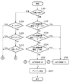
図5は、第1実施形態に係るMFPが原稿の色判別を行い、画像データをBOXに格納する際のフローチャートである。 FIG. 5 is a flowchart when the MFP according to the first embodiment determines the color of the document and stores the image data in the BOX.
まず、UIの操作を簡単に説明する。ユーザは、MFPの原稿台に原稿を置き、コピーメニュー401、または、ボックスメニュー403を選択する。ここで、コピーメニュー401を選択した場合、読み取り原稿をコピー出力すると共に、画像データはBOXに格納される。一方、ボックスメニュー403を選択した場合、画像データのBOXへの格納のみが実行される。
First, a UI operation will be briefly described. The user places a document on the document table of the MFP and selects the
そして、ユーザは404に示す「自動カラー選択」または405〜408に示す「フルカラー」「白黒」「単色カラー」「2色カラー」の手動カラー選択の何れかを選択する。その後、MFP101の原稿台に原稿を置き、操作部203のスタートボタン(不図示)を押下すると、原稿画像がスキャナ部201により読み込まれる(入力される)。なお、以下の各ステップはMFP101の制御ユニット204により実行される。
Then, the user selects either “automatic color selection” indicated by 404 or manual color selection “full color”, “monochrome”, “single color”, or “two color” indicated by 405 to 408. Thereafter, when an original is placed on the original platen of the
ステップS501では、ユーザにより自動/手動の何れのカラー選択がされているかを判別する。404に示す「自動カラー選択」が選択されている場合、ステップS502〜S504を実行し、原稿の種別の判定を行う。なお、この処理(ASC判定)の詳細については後述する。その他の405〜408に示す「フルカラー」「白黒」「単色カラー」「2色カラー」が選択されている場合、ステップS508〜S510で、ユーザにより選択されたカラーの判定を行う。 In step S501, it is determined which color is selected automatically or manually by the user. If “automatic color selection” shown in 404 is selected, steps S502 to S504 are executed to determine the type of document. The details of this process (ASC determination) will be described later. When “full color”, “monochrome”, “single color”, and “two-color” shown in 405 to 408 are selected, the color selected by the user is determined in steps S508 to S510.
自動/手動のカラー選択により、「カラー(フルカラー)」の原稿であると判定した場合はステップS505に進み、スキャナ部201で読み込んだ画像データ(以下、読取画像データ)のフルカラー処理を行う。一方、「白黒」「単色カラー」「2色カラー」の原稿であると判定した場合はステップS506に進み、読取画像データのモノクロ処理を実行する。 If it is determined by automatic / manual color selection that the document is “color (full color)”, the process advances to step S505 to perform full color processing of image data read by the scanner unit 201 (hereinafter, read image data). On the other hand, if it is determined that the document is “monochrome”, “single color”, or “two-color”, the process proceeds to step S506, and monochrome processing of the read image data is executed.
ステップS507では、ステップS505で生成したフルカラー画像データ、あるいは、ステップS506で生成したモノクロ画像データをBOX保存する。 In step S507, the full color image data generated in step S505 or the monochrome image data generated in step S506 is stored in a BOX.
<動作の詳細>
『ACS判定』
上述の通り、ステップS501で「自動カラー選択」が選択されている場合、ステップS502〜S504におけるデータ判別により、読取画像データが、モノクロ、モノカラー、2色カラーの何れかであるかの判定が行われる。ここでは、この判定処理をAuto Color Select判定(以下、ACS判定)と呼ぶ。
<Details of operation>
"ACS judgment"
As described above, when “automatic color selection” is selected in step S501, it is determined whether the read image data is monochrome, monocolor, or two-color color by data discrimination in steps S502 to S504. Done. Here, this determination process is referred to as Auto Color Select determination (hereinafter, ACS determination).
ステップS502では、読取画像データがモノクロか否かを判定する。無彩色のみの場合はモノクロと判定されステップS506に進み、有彩色を含む場合はカラーと判定されステップS503に進む。 In step S502, it is determined whether the read image data is monochrome. If it is only an achromatic color, it is determined to be monochrome, and the process proceeds to step S506. If it includes a chromatic color, it is determined to be a color, and the process proceeds to step S503.
ステップS503では、読取画像データがモノカラーか否かを判定する。有彩色が1色である場合はモノカラーと判定されステップS506に進み、有彩色を2色以上含む場合はステップS504に進む。 In step S503, it is determined whether the read image data is monochromatic. When the chromatic color is one color, it is determined as a mono color and the process proceeds to step S506, and when two or more chromatic colors are included, the process proceeds to step S504.
ステップS504では、読取画像データが2色カラーか否かを判定する。有彩色が2色である場合は2色カラーと判定されステップS506に進み、有彩色を3色以上含む場合はフルカラーと判定されステップS505に進む。 In step S504, it is determined whether the read image data is two-color. If there are two chromatic colors, it is determined as two colors and the process proceeds to step S506. If three or more chromatic colors are included, it is determined as full color and the process proceeds to step S505.
次に、ACS判定について図9〜12を参照しさらに詳細に説明する。 Next, ACS determination will be described in more detail with reference to FIGS.
図9は、読込画像データをACS判定する際の処理フローの一例を示す。 FIG. 9 shows an example of a processing flow when the read image data is ACS-determined.
ステップS901では、原稿画像をスキャナ部201で読み込み読取画像データを生成する。
In step S901, a document image is read by the
ステップS902では、ステップS901で生成した読取画像データに対して、スキャナ画像特有の画像処理、例えば各種フィルタ処理、ガンマ変換や色空間変換を実行する。 In step S902, image processing unique to the scanner image, such as various filter processes, gamma conversion, and color space conversion, is performed on the read image data generated in step S901.
ステップS903では、ステップS902で処理した読取画像データに対して、色分布を導出する。図10は、原稿の一例を示す図である。また、図11、図12は、導出される色分布の例を示す図である。図11、12において、記号“×”は各画素に対応する色の対応位置を示す。図11、図12においては、色分布として、”色相”および”明度”を基準とした分布図を利用しているが、色に関する他の量(色差、彩度など)を利用しても良い。 In step S903, a color distribution is derived for the read image data processed in step S902. FIG. 10 is a diagram illustrating an example of a document. 11 and 12 are diagrams illustrating examples of the derived color distribution. In FIGS. 11 and 12, the symbol “x” indicates the corresponding position of the color corresponding to each pixel. In FIGS. 11 and 12, distribution diagrams based on “hue” and “brightness” are used as the color distribution, but other amounts (color difference, saturation, etc.) relating to colors may be used. .
ステップS904では、ステップS903で導出した色分布に基づいてACS判定(画像種別判定)を行う。 In step S904, ACS determination (image type determination) is performed based on the color distribution derived in step S903.
・ACSモノカラー判定
図11は、図10における領域1001および1002が共に赤の場合に、ステップS503で作成される色分布の一例を示す図である。ACS判定においては、まず、図11に示す全領域の分布状況を確認する。そして、その結果に基づいて読取画像データに含まれる色の出現頻度の順位を決定する。図11に示す色分布においては、”R”の位置に分布が集中する。その他の位置に関しても分布の状況を確認するが、“R”の位置における出現頻度と比較して極端に少ない。そのため、”R”以外の位置にある分布は、原稿上にあるノイズと判断して無視する。そのため、図11の色分布に対しては、色の順位は“R”が第1位(代表色)になり、その他の色は無視される。つまり、原稿は赤一色で構成されている(すなわちモノカラー画像データ)と判定する。
ACS Monocolor Determination FIG. 11 is a diagram illustrating an example of the color distribution created in step S503 when both the
・ACS2色カラー判定
図12は、図10における領域1001が赤、1002が黒の場合に、ステップS503で作成される色分布の一例を示す図である。この場合、図12の“R”と“BK”の位置に分布が集中する。その他の位置に関しても、分布の状況を確認するが、“R”と“BK” と比較して極端に少ない場合は、原稿上にあるノイズと判断して、無視する。この結果から、色の順位は“R”が第1位(代表色)、“BK”が第2位(代表色)になり、その他の色は無視される。つまり、原稿は赤と黒の二色で構成されている(すなわち2色カラー画像データ)と判定する。
ACS Two-Color Determination FIG. 12 is a diagram illustrating an example of the color distribution created in step S503 when the
・ACSモノクロ判定
なお、上述のACSモノカラー判定の説明において“BK”が第1位になり、その他の色が無視された場合にはモノクロ画像データと判定される。
ACS monochrome determination Note that in the above description of the ACS monocolor determination, “BK” is ranked first, and when other colors are ignored, it is determined as monochrome image data.
『モノクロ処理』
図6は、ステップS506におけるモノクロ処理に関する動作フローチャートである。当該モノクロ処理は、前述したように、手動カラー選択において、白黒406、単色カラー407、2色カラー408が選択されていると判定された場合に実行される。および、自動カラー選択において、「モノクロ」「モノカラー」「2色カラー」と判別された場合に実行される。なお、以下の各ステップはMFP101の制御ユニット204により実行される。
"Monochrome processing"
FIG. 6 is an operation flowchart regarding the monochrome processing in step S506. As described above, the monochrome processing is executed when it is determined in the manual color selection that the monochrome 406, the
ステップS601では、読取画像データに対してモノクロ変換を行う。具体的には、スキャナによって読み取られた読取画像データ(24bit(RGB各色8bit)/画素)をモノクロデータ(1bit/画素 2値化データ)に変換する(2値化データ生成する)。なお、後述するように、グレースケールデータ(8bit/画素)のような多値データとしても良い。以下ではモノクロデータに変換する場合を説明する。なお、モノクロデータへの変換自体に関しては既知の任意の手法が利用可能である。本発明では次に述べる付加情報を生成する点が異なる。 In step S601, monochrome conversion is performed on the read image data. Specifically, the read image data (24 bits (8 bits for each color of RGB) / pixel) read by the scanner is converted into monochrome data (1 bit / pixel binary data) (binary data is generated). As will be described later, multi-value data such as gray scale data (8 bits / pixel) may be used. Hereinafter, a case of converting to monochrome data will be described. It should be noted that any known method can be used for the conversion to monochrome data itself. The present invention is different in that additional information described below is generated.
ステップS602では、付加情報(付加データ)1を生成(付加データ生成)する。付加情報1は、ステップS601において生成されたモノクロデータに対応する有彩/無彩色情報である。つまり、付加情報1は、モノクロデータ全画素に対して各々与えられる1bit/画素の情報であり、ここでは、値が”1”の場合は有彩色、”0”の場合は無彩色とする。
In step S602, additional information (additional data) 1 is generated (additional data generation). The
ステップS603では、付加情報2を生成する。付加情報2は、原稿が「モノクロ」「モノカラー」「2色カラー」のいずれであったかを示す属性情報と、ステップ601において生成されたモノクロデータに対応する色情報から構成される。ここでは、属性情報の値が、”0”の場合モノクロ、”1”の場合モノカラー、”2”の場合2色カラーであるとする。また、色情報としては、「自動カラー選択」の場合、ステップS503、S504で抽出された代表色が設定される。また、手動カラー選択の場合は、図4(b)または図4(c)の設定画面で指定した色が設定される。
In step S603,
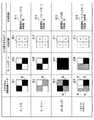
図8は、モノクロ処理およびフルカラー処理により生成されるデータを例示的に示す図である。ここでは、説明を簡単にするため、画像の2x2画素分のみを示している。 FIG. 8 is a diagram exemplarily showing data generated by monochrome processing and full-color processing. Here, for simplification of description, only 2 × 2 pixels of the image are shown.
ここで、801〜804は、読取画像データ(24bit(RGB各色8bit)/画素)である。また、805〜807は、モノクロ処理後のモノクロデータ(1bit/画素)、808は、カラー処理後のカラーデータ(24bit(RGB各色8bit)/画素)である。そして、809〜812、は、付加情報1(有彩/無彩色情報)、813〜816は、付加情報2(属性情報、色情報)である。
Here,
例えば、モノカラー画像802に対しては、モノクロ処理後のモノクロデータは、806に示すモノクロ1bitのデータとなる。また、付加情報1は、806の赤色の画素が有彩色と判断され、それ以外の画素は、無彩色と判断されるため、810に示すデータとなる。また、付加情報2は、属性情報=1(モノカラー)、色情報=赤を示す814のデータとなる。
For example, for a
このようにして生成された、モノクロデータ、付加情報1(有彩/無彩色情報)、付加情報2(属性情報、色情報)は、ステップS507において、BOXに保存される。なお、これらのデータを公知の可逆圧縮(例えば、MMR圧縮、ZIP圧縮など)で圧縮することにより、BOX領域へのデータ格納効率が向上する。なお、ここでは生成される3種類のデータを分けて説明しているが、保存されるときのデータとしては単一のファイルであっても良い。例えば、付加情報をモノクロデータの先頭(ヘッダ)部分などに付与するよう構成しても良い。また、ステップS505におけるカラー処理においては、一般にはJPEG方式で圧縮され、ステップ507において、BOXに保存される。
The monochrome data, additional information 1 (chromatic / achromatic color information), and additional information 2 (attribute information, color information) generated in this way are stored in the BOX in step S507. It should be noted that the data storage efficiency in the BOX area is improved by compressing these data using known lossless compression (for example, MMR compression, ZIP compression, etc.). Here, the three types of data to be generated are described separately, but a single file may be used as the data when saved. For example, the additional information may be added to the head (header) portion of the monochrome data. In the color processing in step S505, the image is generally compressed by the JPEG method and stored in the BOX in
このようにして、「モノクロ」「モノカラー」「2色カラー」である原稿をMFP101のスキャナで読み取り、モノクロデータ107、及び付加情報1および2としてBOX106に格納することが出来る。なお、ここではスキャナ部201による読取画像について説明を行ったが、MFP101にネットワーク接続されたホストコンピュータからプリンタドライバを介して送られる画像データ(PDLデータなど)に対し同様の処理を行っても良い。
In this way, a document of “monochrome”, “monocolor”, and “two-color” can be read by the scanner of the
<モノクロデータの出力>
図7は、BOXに保存されたモノクロデータを出力(プリント、送信)する際のフローチャートである。また、図13は、BOXメニュー選択時の設定画面の例を示す図である。
<Monochrome data output>
FIG. 7 is a flowchart for outputting (printing or transmitting) monochrome data stored in a BOX. FIG. 13 is a diagram showing an example of a setting screen when the BOX menu is selected.
ユーザによりボックスメニュー403が選択されると図13(a)の画面が表示される。当該画面で、ユーザは所望の画像が格納されているボックス番号00に対応するボタン411を指定する。すると、ボックス番号00に対応する図13(a)の画面が表示される。次に、所望の画像412を選択し、該画像をプリントしたい場合は、プリントボタン413、送信したい場合は、送信ボタン414を押下する。
When the user selects the
ステップS701では、ユーザから、自動カラー選択または手動のカラー選択を受け付ける。ここで、ユーザは、404に示す「自動カラー選択」、または、その他の405〜408に示す「フルカラー」「白黒」「単色カラー」「2色カラー」を選択する。図4の404〜408は、コピーメニュー401画面上のメニューであるが、同様のメニューがボックスメニュー403画面上にもあるものとする。「自動カラー選択」が選択されたときはステップS702に進み、「フルカラー」「白黒」「単色カラー」「2色カラー」が選択されたときはステップS708に進む。なお、手動による出力(ステップS708からS710)については、モノクロデータを出力(プリント、送信)する際の色を手動で指定する。つまり、付加情報に格納されたじょうほうにかかわらず、強制的に色指定を行う。ただし、この処理については従来とほぼ同様であるため説明は省略する。
In step S701, automatic color selection or manual color selection is received from the user. Here, the user selects “automatic color selection” indicated by 404 or “full color”, “monochrome”, “monochromatic color”, and “two-color color” indicated by 405 to 408.
ステップS702〜S704では、MFP101は、BOXに格納されている付加情報1、2を用いてモノクロデータの色再現処理を行う。ステップS702〜S704では、付加情報2に基づいて、出力が指定されたモノクロデータが、モノクロか、モノカラーか、2色カラーかの判別を行う。
In steps S702 to S704, the
これにより、指定されたモノクロデータが、モノクロか、モノカラーか、2色カラーであると判定された場合は、ステップS706に進む。一方、モノクロか、モノカラーか、2色カラーの何れでもないと判定された場合は、フルカラーと判定し、ステップS705に進む。なお、ステップS705では、出力色処理(2)として、通常の公知のフルカラーデータ処理を実行する。 As a result, if it is determined that the designated monochrome data is monochrome, monocolor, or two-color, the process proceeds to step S706. On the other hand, if it is determined that the image is not monochrome, mono color, or two-color, it is determined as full color, and the process proceeds to step S705. In step S705, a normal well-known full color data process is executed as the output color process (2).
ステップS706では、出力色処理(1)を実行する。具体的には、付加情報1および付加情報2に格納された色情報に基づいて、指定されたモノクロデータを、モノクロ、モノカラー、2色カラーの何れかに対応する画像データに変換する。ここで、色再現処理とは、有彩色の画素である場合、付加情報2を利用した色情報を割り当て(置換)、無彩色の画素である場合、白、または、黒の色情報を割り当てる処理を意味する。また、出力色処理(1)では、RGB色空間からプリンタデバイス色空間への色処理、RGB色空間からモニタRGB色空間への色変換なども含まれる。つまり、プリント出力、及びデータ送信出力に最低限必要な出力画像処理も含んでいるものとする。
In step S706, output color processing (1) is executed. Specifically, based on the color information stored in the
また、データ送信出力の場合は、ステップS705、S706、または、Sステップ707において、解像度変換処理、圧縮処理を行うことが一般的である。 In the case of data transmission output, in step S705, S706, or Sstep 707, resolution conversion processing and compression processing are generally performed.
以上説明したように第1実施形態に係るMFPによる画像処理を行うことにより、データ容量を抑えつつ、色再現可能な形式で画像データをBOX格納することが可能となる。 As described above, by performing image processing by the MFP according to the first embodiment, it is possible to store image data in a box in a color reproducible format while suppressing the data capacity.
つまり、原稿がフルカラーである場合に、ユーザが、モノクロでBOX格納時に有彩/無彩フラグを同時に格納する。2色プリントを希望する場合は、有彩/無彩フラグを使用し、UIからの指定色を有彩箇所に黒を無彩箇所に使用する。一方、原稿が2色、モノカラーである場合に、原稿を読み取って2色原稿もしくはモノカラー原稿の場合には、BOXにグレースケールデータとして格納し、さらに有彩/無彩判定フラグと色成分データを格納する。上記データをプリント出力、もしくは送信時には、有彩/無彩フラグを元に有彩色部分には、色成分データの色を無彩色成分には、黒を用いて2色、もしくは、モノカラー出力を実現する。 That is, when the original is full color, the user stores the chromatic / achromatic flag at the same time when storing the BOX in monochrome. When two-color printing is desired, the chromatic / achromatic flag is used, and the designated color from the UI is used for the chromatic portion and black is used for the achromatic portion. On the other hand, when the original is a two-color or mono-color original, and the original is read and stored as a two-color original or a mono-color original, it is stored in the BOX as grayscale data, and further a chromatic / achromatic determination flag and a color component Store the data. When printing or sending the above data, the color component data is used for the chromatic part based on the chromatic / achromatic flag, and the color component data is black for the achromatic component. Realize.
例えば、A4の原稿用紙サイズ、600dpiである場合、フルカラーデータは、非圧縮状態で約100Mbyteであり、これを圧縮して数10Mbyteである。また、一般的にJPEGなどの非可逆圧縮が用いられるため画像劣化が生じる。これに対して、第1実施形態で説明した方法においては、モノクロデータ(約4Mbyte)+付加情報1(約4Mbyte)+付加情報2(数バイト)である。これを圧縮して数Mbyte〜8Mbyte、かつ通常可逆圧縮が用いられるため、画像劣化は生じない。 For example, in the case of an A4 original paper size of 600 dpi, the full-color data is about 100 Mbytes in an uncompressed state, and is compressed to several tens of Mbytes. In addition, image loss occurs because lossy compression such as JPEG is generally used. In contrast, in the method described in the first embodiment, monochrome data (about 4 Mbytes) + additional information 1 (about 4 Mbytes) + additional information 2 (several bytes). Since this is compressed and several Mbytes to 8 Mbytes and usually reversible compression is used, image degradation does not occur.
(変形例)
第1実施形態においては、BOXに格納する付加情報1(有彩/無彩色情報)は、各画素を1bitのデータで表現するとして説明を行った。しかし、各画素を2bit以上のデータ(Nビット値:Nは2以上の自然数)で表現しても良い。その場合、4色以上の画像データとして色を再現することが可能となる。具体的には、各画素を2bitとする場合、有彩色1〜3、無彩色という4通りの情報を原稿読み取り時に抽出しておき、これらを付加情報1として保存する。また、付加情報2の色情報を色情報1〜3として保存する。これにより、4色の色再現が可能となる。
(Modification)
In the first embodiment, the additional information 1 (chromatic / achromatic information) stored in the BOX has been described as representing each pixel as 1-bit data. However, each pixel may be expressed by data of 2 bits or more (N bit value: N is a natural number of 2 or more). In that case, colors can be reproduced as image data of four or more colors. Specifically, when each pixel is set to 2 bits, four types of information,
(他の実施形態)
以上、本発明の実施形態について詳述したが、本発明は、複数の機器から構成されるシステムに適用しても良いし、また、一つの機器からなる装置に適用しても良い。
(Other embodiments)
Although the embodiments of the present invention have been described in detail above, the present invention may be applied to a system constituted by a plurality of devices or may be applied to an apparatus constituted by one device.
なお、本発明は、前述した実施形態の機能を実現するプログラムを、システム或いは装置に直接或いは遠隔から供給し、そのシステム或いは装置が、供給されたプログラムコードを読み出して実行することによっても達成される。従って、本発明の機能処理をコンピュータで実現するために、コンピュータにインストールされるプログラムコード自体も本発明の技術的範囲に含まれる。 The present invention can also be achieved by supplying a program that realizes the functions of the above-described embodiments directly or remotely to a system or apparatus, and the system or apparatus reads and executes the supplied program code. The Accordingly, the program code itself installed in the computer in order to realize the functional processing of the present invention by the computer is also included in the technical scope of the present invention.
その場合、プログラムの機能を有していれば、オブジェクトコード、インタプリタにより実行されるプログラム、OSに供給するスクリプトデータ等、プログラムの形態を問わない。 In this case, the program may be in any form as long as it has a program function, such as an object code, a program executed by an interpreter, or script data supplied to the OS.
プログラムを供給するための記録媒体としては、例えば、フロッピー(登録商標)ディスク、ハードディスク、光ディスク(CD、DVD)、光磁気ディスク、磁気テープ、不揮発性のメモリカード、ROMなどがある。 Examples of the recording medium for supplying the program include a floppy (registered trademark) disk, a hard disk, an optical disk (CD, DVD), a magneto-optical disk, a magnetic tape, a nonvolatile memory card, and a ROM.
その他、プログラムの供給方法としては、クライアントコンピュータのブラウザを用いてインターネットのホームページに接続し、ホームページから本発明のコンピュータプログラムそのものを供給できる。もしくは圧縮され自動インストール機能を含むファイルをハードディスク等の記録媒体にダウンロードすることによっても供給できる。また、本発明のプログラムを構成するプログラムコードを複数のファイルに分割し、それぞれのファイルを異なるホームページからダウンロードすることによっても実現可能である。つまり、本発明の機能処理をコンピュータで実現するためのプログラムファイルを複数のユーザに対してダウンロードさせるWWWサーバも、本発明のクレームに含まれるものである。 As another program supply method, the browser of a client computer can be used to connect to a home page on the Internet, and the computer program itself of the present invention can be supplied from the home page. Alternatively, it can be supplied by downloading a compressed file including an automatic installation function to a recording medium such as a hard disk. It can also be realized by dividing the program code constituting the program of the present invention into a plurality of files and downloading each file from a different homepage. That is, a WWW server that allows a plurality of users to download a program file for realizing the functional processing of the present invention on a computer is also included in the claims of the present invention.
また、本発明のプログラムを暗号化してCD−ROM等の記憶媒体に格納してユーザに配布する。そして、所定の条件をクリアしたユーザに対し、インターネットを介してホームページから暗号化を解く鍵情報をダウンロードさせる。その鍵情報を使用することにより暗号化されたプログラムを実行してコンピュータにインストールさせて実現することも可能である。 Further, the program of the present invention is encrypted, stored in a storage medium such as a CD-ROM, and distributed to users. Then, the user who has cleared the predetermined condition is allowed to download key information for decryption from the homepage via the Internet. By using the key information, an encrypted program can be executed and installed in a computer.
また、コンピュータが、読み出したプログラムを実行することによって、前述した実施形態の機能が実現される。その他、そのプログラムの指示に基づき、コンピュータ上で稼動しているOSなどが、実際の処理の一部または全部を行い、その処理によっても前述した実施形態の機能が実現され得る。 Further, the functions of the above-described embodiments are realized by the computer executing the read program. In addition, based on the instructions of the program, an OS or the like running on the computer performs part or all of the actual processing, and the functions of the above-described embodiments can also be realized by the processing.
さらに、記録媒体から読み出されたプログラムが、コンピュータに挿入された機能拡張ボードやコンピュータに接続された機能拡張ユニットに備わるメモリに書き込まれる。その後、そのプログラムの指示に基づき、その機能拡張ボードや機能拡張ユニットに備わるCPUなどが実際の処理の一部または全部を行い、その処理によっても前述した実施形態の機能が実現される。 Further, the program read from the recording medium is written in a memory provided in a function expansion board inserted into the computer or a function expansion unit connected to the computer. Thereafter, the CPU of the function expansion board or function expansion unit performs part or all of the actual processing based on the instructions of the program, and the functions of the above-described embodiments are realized by the processing.
Claims (6)
前記画像入力手段によって入力された画像データに含まれる代表色と該画像データの画像種別とを判定する判定手段と、
前記画像データを、色情報を含まない2値化データへ変換する2値化データ生成手段と、
前記2値化データ生成手段によって生成された2値化データに対応する有彩/無彩色情報と、前記判定手段によって判定された画像種別及び代表色の情報と、を含む付加データを生成する付加データ生成手段と、
前記2値化データと前記付加データとを記憶する記憶手段と、
を備えることを特徴とする画像処理装置。 Image input means for reading a document image and inputting it as image data;
Determining means for determining a representative color included in the image data input by the image input means and an image type of the image data ;
Binarized data generating means for converting the image data into binarized data not including color information;
Addition for generating additional data including chromatic / achromatic color information corresponding to the binarized data generated by the binarized data generating unit and information on the image type and representative color determined by the determining unit Data generation means;
Storage means for storing the binarized data and the additional data;
An image processing apparatus comprising:
前記判定手段は、前記操作部によるユーザの指示入力に基づいて前記代表色を設定することを特徴とする請求項1または2に記載の画像処理装置。 Furthermore, an operation unit for receiving an instruction input from the user is provided,
The image processing apparatus according to claim 1, wherein the determination unit sets the representative color based on a user instruction input from the operation unit.
前記画像データが、無彩色のみから構成されるモノクロ画像データ、1つの無彩色および1つの有彩色から構成されるモノカラー画像データ、および、2つの有彩色から構成される2色カラー画像データの何れであるかを示すことを特徴とする請求項1乃至3の何れか一項に記載の画像処理装置。 The image type is
The image data includes monochrome image data composed only of achromatic colors, monocolor image data composed of one achromatic color and one chromatic color, and two-color color image data composed of two chromatic colors. the image processing apparatus according to any one of claims 1 to 3, wherein the indicating whether it.
前記画像入力手段によって入力された画像データに含まれる代表色と該画像データの画像種別とを判定する判定手段と、
前記画像データを、色情報を含まず、各画素がNビット値(Nは前記画像データの各画素の色深度以下の自然数)で表現されるデータに変換するデータ生成手段と、
前記データ生成手段によって生成されたデータに対応する有彩/無彩色情報と、前記判定手段によって判定された画像種別及び代表色の情報と、を含む付加データを生成する付加データ生成手段と、
前記Nビット値で表現されるデータと前記付加データとを記憶する記憶手段と、
を備えることを特徴とする画像処理装置。 Image input means for reading a document image and inputting it as image data;
Determining means for determining a representative color included in the image data input by the image input means and an image type of the image data ;
Data generating means for converting the image data into data that does not include color information and each pixel is represented by an N-bit value (N is a natural number equal to or less than the color depth of each pixel of the image data );
Additional data generation means for generating additional data including chromatic / achromatic information corresponding to the data generated by the data generation means, and information on the image type and representative color determined by the determination means;
Storage means for storing the data represented by the N-bit value and the additional data;
An image processing apparatus comprising:
原稿画像を読取って画像データとして入力する画像入力工程と、
前記画像入力工程によって入力された画像データに含まれる代表色と該画像データの画像種別とを判定する判定工程と、
前記画像データを、色情報を含まない2値化データへ変換する2値化データ生成工程と、
前記2値化データ生成工程によって生成された2値化データに対応する有彩/無彩色情報と、前記判定工程によって判定された画像種別及び代表色の情報と、を含む付加データを生成する付加データ生成工程と、
前記2値化データと前記付加データとを記憶する記憶工程と、
を備えることを特徴とする画像処理装置の制御方法。 A control method for an image processing apparatus, comprising:
An image input step of inputting an image data by reading an original manuscript image,
A determination step of determining the image type of the representative color and the image data included in the image data input by the previous SL image input step,
The pre Symbol image data, and binary data generating step of converting the binary data does not include color information,
Generating additional data including previous SL and binary data generating step chromatic / achromatic information corresponding to the binary data generated by, and an image type and the representative color of the information determined by said determination step Additional data generation process;
A storage step of storing a before and Symbol binary data the additional data,
An image processing apparatus control method comprising:
Priority Applications (2)
| Application Number | Priority Date | Filing Date | Title |
|---|---|---|---|
| JP2007077158A JP4979428B2 (en) | 2007-03-23 | 2007-03-23 | Image processing apparatus and control method thereof |
| US12/051,489 US20080231903A1 (en) | 2007-03-23 | 2008-03-19 | Image processing apparatus and control method thereof |
Applications Claiming Priority (1)
| Application Number | Priority Date | Filing Date | Title |
|---|---|---|---|
| JP2007077158A JP4979428B2 (en) | 2007-03-23 | 2007-03-23 | Image processing apparatus and control method thereof |
Publications (3)
| Publication Number | Publication Date |
|---|---|
| JP2008236668A JP2008236668A (en) | 2008-10-02 |
| JP2008236668A5 JP2008236668A5 (en) | 2010-05-06 |
| JP4979428B2 true JP4979428B2 (en) | 2012-07-18 |
Family
ID=39774380
Family Applications (1)
| Application Number | Title | Priority Date | Filing Date |
|---|---|---|---|
| JP2007077158A Expired - Fee Related JP4979428B2 (en) | 2007-03-23 | 2007-03-23 | Image processing apparatus and control method thereof |
Country Status (2)
| Country | Link |
|---|---|
| US (1) | US20080231903A1 (en) |
| JP (1) | JP4979428B2 (en) |
Families Citing this family (3)
| Publication number | Priority date | Publication date | Assignee | Title |
|---|---|---|---|---|
| JP4865771B2 (en) * | 2008-08-27 | 2012-02-01 | シャープ株式会社 | Image processing apparatus, image forming apparatus, image processing method, image processing program, and computer-readable recording medium |
| JP5678584B2 (en) * | 2009-12-16 | 2015-03-04 | 株式会社リコー | Image processing apparatus, image processing method, and program |
| JP2023013472A (en) * | 2021-07-16 | 2023-01-26 | セイコーエプソン株式会社 | printer |
Family Cites Families (17)
| Publication number | Priority date | Publication date | Assignee | Title |
|---|---|---|---|---|
| US5128748A (en) * | 1989-02-15 | 1992-07-07 | Hitachi, Ltd. | Image processing system and apparatus for processing color documents |
| DE69030178T2 (en) * | 1989-12-15 | 1997-08-14 | Hitachi Ltd | DEVICE AND METHOD FOR STORING IMAGES |
| JPH05145778A (en) * | 1991-11-15 | 1993-06-11 | Ricoh Co Ltd | Color image transmission system |
| US5343311A (en) * | 1992-04-14 | 1994-08-30 | Electronics For Imaging, Inc. | Indexed processing of color image data |
| JPH08214171A (en) * | 1995-02-01 | 1996-08-20 | Canon Inc | Image communication equipment and its method |
| US5680526A (en) * | 1995-06-06 | 1997-10-21 | Apple Computer, Inc. | Method and system for selectively rendering image data in a bi-level or multi-level format |
| JPH09163169A (en) * | 1995-12-04 | 1997-06-20 | Minolta Co Ltd | Digital color copying machine |
| US6518981B2 (en) * | 1997-11-12 | 2003-02-11 | Canon Kabushiki Kaisha | Generating and using a color palette |
| JP2002019200A (en) * | 2000-07-10 | 2002-01-23 | Fuji Xerox Co Ltd | Imaging apparatus |
| US6847333B2 (en) * | 2000-10-13 | 2005-01-25 | Edward Bokhour | Method of and system for low-bandwidth transmission of color video |
| JP4164225B2 (en) * | 2000-11-07 | 2008-10-15 | 理想科学工業株式会社 | Image forming system, image forming apparatus, and image forming program |
| JP2002314825A (en) * | 2001-04-09 | 2002-10-25 | Sharp Corp | Color adjustment device and method therefor |
| JP2003051951A (en) * | 2001-08-06 | 2003-02-21 | Canon Inc | Image input output device and control method therefor |
| JP4071701B2 (en) * | 2003-11-11 | 2008-04-02 | 富士通株式会社 | Color image compression method and color image compression apparatus |
| EP1555804A3 (en) * | 2004-01-19 | 2006-08-16 | Ricoh Company, Ltd. | Image processing apparatus, image processing program and storage medium |
| US7991238B2 (en) * | 2004-04-30 | 2011-08-02 | Neiversan Networks Co. Llc | Adaptive compression of multi-level images |
| JP2005245025A (en) * | 2005-04-08 | 2005-09-08 | Kyocera Mita Corp | Image processing apparatus |
-
2007
- 2007-03-23 JP JP2007077158A patent/JP4979428B2/en not_active Expired - Fee Related
-
2008
- 2008-03-19 US US12/051,489 patent/US20080231903A1/en not_active Abandoned
Also Published As
| Publication number | Publication date |
|---|---|
| JP2008236668A (en) | 2008-10-02 |
| US20080231903A1 (en) | 2008-09-25 |
Similar Documents
| Publication | Publication Date | Title |
|---|---|---|
| US8259345B2 (en) | Image processing apparatus, control method of image processing apparatus, program, and storage medium | |
| US8339627B2 (en) | Image processing apparatus, method and program | |
| JP5145965B2 (en) | Image processing apparatus, image processing method, and program | |
| JP5164368B2 (en) | Image processing apparatus and image processing method | |
| US20070139704A1 (en) | Image communication apparatus and image communication method | |
| KR20060043202A (en) | Printing information processing device, printing device, printing information processing method and printing system | |
| JP2006094475A (en) | Image filing apparatus and method | |
| JP2009272774A (en) | Image processor, image forming apparatus, image processing method, and computer program | |
| KR20080039206A (en) | Image processing apparatus and control method for image processing apparatus | |
| JP4979428B2 (en) | Image processing apparatus and control method thereof | |
| JP5335305B2 (en) | Image processing apparatus, image processing method, and program | |
| JP4815311B2 (en) | Image processing apparatus and image processing method | |
| JP2003234866A (en) | Method and system for transmitting image and image data matching device | |
| JP2004266470A (en) | Apparatus and method for processing image | |
| JP2006229386A (en) | Image processor | |
| US8115963B2 (en) | Image processing apparatus, image processing method, and computer program product | |
| JP2006211003A (en) | Image processor | |
| US8780374B2 (en) | Image processing apparatus and image processing method | |
| JP4990340B2 (en) | Image processing apparatus, image forming apparatus, image processing method, image processing program, and recording medium | |
| JP2011229074A (en) | Image processing device, image processing method, and image processing system | |
| JP2007166510A (en) | Image processing apparatus, control method of image processing apparatus, program, and storage medium | |
| JP2006166134A (en) | Image communication equipment, its control method, program, and storage medium | |
| US8170353B2 (en) | Information processing apparatus and control method thereof | |
| JP2006041938A (en) | Image processing unit | |
| JP2010074424A (en) | Image processing system and image processing method |
Legal Events
| Date | Code | Title | Description |
|---|---|---|---|
| A521 | Request for written amendment filed |
Free format text: JAPANESE INTERMEDIATE CODE: A523 Effective date: 20100323 |
|
| A621 | Written request for application examination |
Free format text: JAPANESE INTERMEDIATE CODE: A621 Effective date: 20100323 |
|
| A977 | Report on retrieval |
Free format text: JAPANESE INTERMEDIATE CODE: A971007 Effective date: 20110914 |
|
| A131 | Notification of reasons for refusal |
Free format text: JAPANESE INTERMEDIATE CODE: A131 Effective date: 20110922 |
|
| A521 | Request for written amendment filed |
Free format text: JAPANESE INTERMEDIATE CODE: A523 Effective date: 20111118 |
|
| TRDD | Decision of grant or rejection written | ||
| A01 | Written decision to grant a patent or to grant a registration (utility model) |
Free format text: JAPANESE INTERMEDIATE CODE: A01 Effective date: 20120413 |
|
| A01 | Written decision to grant a patent or to grant a registration (utility model) |
Free format text: JAPANESE INTERMEDIATE CODE: A01 |
|
| A61 | First payment of annual fees (during grant procedure) |
Free format text: JAPANESE INTERMEDIATE CODE: A61 Effective date: 20120417 |
|
| FPAY | Renewal fee payment (event date is renewal date of database) |
Free format text: PAYMENT UNTIL: 20150427 Year of fee payment: 3 |
|
| LAPS | Cancellation because of no payment of annual fees |