JP4977534B2 - Sensor network system and sensor node - Google Patents
Sensor network system and sensor node Download PDFInfo
- Publication number
- JP4977534B2 JP4977534B2 JP2007151866A JP2007151866A JP4977534B2 JP 4977534 B2 JP4977534 B2 JP 4977534B2 JP 2007151866 A JP2007151866 A JP 2007151866A JP 2007151866 A JP2007151866 A JP 2007151866A JP 4977534 B2 JP4977534 B2 JP 4977534B2
- Authority
- JP
- Japan
- Prior art keywords
- time
- sensor node
- sensor
- base station
- network system
- Prior art date
- Legal status (The legal status is an assumption and is not a legal conclusion. Google has not performed a legal analysis and makes no representation as to the accuracy of the status listed.)
- Expired - Fee Related
Links
Images


Classifications
-
- G—PHYSICS
- G06—COMPUTING; CALCULATING OR COUNTING
- G06F—ELECTRIC DIGITAL DATA PROCESSING
- G06F1/00—Details not covered by groups G06F3/00 - G06F13/00 and G06F21/00
- G06F1/04—Generating or distributing clock signals or signals derived directly therefrom
- G06F1/14—Time supervision arrangements, e.g. real time clock
-
- H—ELECTRICITY
- H04—ELECTRIC COMMUNICATION TECHNIQUE
- H04J—MULTIPLEX COMMUNICATION
- H04J3/00—Time-division multiplex systems
- H04J3/02—Details
- H04J3/06—Synchronising arrangements
- H04J3/0635—Clock or time synchronisation in a network
- H04J3/0638—Clock or time synchronisation among nodes; Internode synchronisation
-
- H—ELECTRICITY
- H04—ELECTRIC COMMUNICATION TECHNIQUE
- H04W—WIRELESS COMMUNICATION NETWORKS
- H04W74/00—Wireless channel access, e.g. scheduled or random access
- H04W74/04—Scheduled or contention-free access
- H04W74/06—Scheduled or contention-free access using polling
-
- H—ELECTRICITY
- H04—ELECTRIC COMMUNICATION TECHNIQUE
- H04W—WIRELESS COMMUNICATION NETWORKS
- H04W88/00—Devices specially adapted for wireless communication networks, e.g. terminals, base stations or access point devices
- H04W88/08—Access point devices
-
- H—ELECTRICITY
- H04—ELECTRIC COMMUNICATION TECHNIQUE
- H04W—WIRELESS COMMUNICATION NETWORKS
- H04W88/00—Devices specially adapted for wireless communication networks, e.g. terminals, base stations or access point devices
- H04W88/16—Gateway arrangements
Description
本発明は、省電力化のために一定時間間隔で起動状態と停止状態を繰り返す間欠動作を行うセンサノードの利用システムに関し、特に、システム全体で時刻同期を取る技術に関する。 The present invention relates to a sensor node utilization system that performs an intermittent operation in which a start state and a stop state are repeated at regular time intervals for power saving, and more particularly, to a technique for synchronizing time in the entire system.
従来、センサネットワークで用いられる無線通信方式として、ZIGBEE(登録商標)があった(例えば、非特許文献1参照)。
Conventionally, there has been ZIGBEE (registered trademark) as a wireless communication method used in sensor networks (for example, see Non-Patent Document 1).
また、従来、地震による震源位置特定の手法として、グリッドサーチ法があった(例えば、非特許文献2参照)。 Conventionally, there has been a grid search method as a method for specifying an epicenter location due to an earthquake (see, for example, Non-Patent Document 2).
近年、センサ機能を搭載した小型無線センサノード(以下、センサノード)、中継機、基地局、及びセンサネット管理サーバ(以下、管理サーバ)から構成されるセンサネットシステムの開発が進められている。センサノードは、人又は場所の状態等(センサデータ)を観測し、観測したセンサデータを中継機によりマルチホップに中継し、基地局を経由して管理サーバに送信する。管理サーバは、受信したセンサデータに基づいて、各種処理を実行する。 In recent years, development of a sensor network system including a small wireless sensor node (hereinafter referred to as a sensor node) equipped with a sensor function, a relay station, a base station, and a sensor network management server (hereinafter referred to as a management server) has been promoted. The sensor node observes the state of a person or a place (sensor data), relays the observed sensor data in a multi-hop by a relay, and transmits it to the management server via the base station. The management server executes various processes based on the received sensor data.
センサネットシステムにおけるキーデバイスは、小型、低電力を特徴とするセンサノードである。小型であるが故に環境や人を含むあらゆるモノへ付けることが可能となり、低電力であるが故に外部給電することなく電池で数年間稼動させることができる。さらに無線で通信するが故に、基地局または中継機を介して広範囲へ配置することが可能である。 A key device in the sensor network system is a sensor node characterized by small size and low power. Because it is small in size, it can be attached to everything including the environment and people, and because of its low power, it can be operated for several years with a battery without external power supply. Furthermore, since it communicates by radio | wireless, it is possible to arrange | position to a wide range via a base station or a relay machine.
センサノードにおける特徴的な動作として、間欠動作がある。これは、センシングやデータ送信のようなタスクを実行する時のみ必要なハードウェアを駆動し、実行すべきタスクがない時はセンサ、高周波回路(RF)等の周辺ハードウェアは完全に停止し、マイコンも低電力モードで休眠させるという動作である。間欠動作を行うことにより、センサノードは、限られたバッテリの下で長時間動作が可能となる。 As a characteristic operation in the sensor node, there is an intermittent operation. This drives the necessary hardware only when performing tasks such as sensing and data transmission, and when there are no tasks to be performed, peripheral hardware such as sensors and high-frequency circuits (RF) are completely stopped. The microcomputer also sleeps in the low power mode. By performing the intermittent operation, the sensor node can operate for a long time under a limited battery.
マイコンが所定の休眠時間を満了すると、タイマ部が割り込みを発生させることにより、マイコンは通常動作モードへ復帰する。そして所定の手順に従い、センシングを実行し、センシングしたデータを送信し、自分宛のデータがある場合にはポーリング(Polling)により受信し、該データの処理を行う。その時点で実行すべき全てのタスクが終了すれば、再び所定時間の休眠に入る。休眠期間の合間のタスク処理期間の長さは数10ミリ秒から長くても1秒程度なので、センサノードはほとんどその時間は休眠状態にあることになる。 When the microcomputer expires a predetermined sleep time, the timer unit generates an interrupt, so that the microcomputer returns to the normal operation mode. Then, in accordance with a predetermined procedure, sensing is performed, the sensed data is transmitted, and if there is data addressed to itself, it is received by polling, and the data is processed. When all the tasks to be executed at that time are completed, the computer enters sleep for a predetermined time again. Since the length of the task processing period between the sleep periods is about 1 second at the longest from several tens of milliseconds, the sensor node is almost in the sleep state for that time.
なお、間欠動作の基本的な特徴は「タスクを実行する必要がない時は休眠する」ことであるので、タスクのスケジューリングの方法によって間欠動作の実施方法には多様な変化が考えられる。例えばセンサノードが複数のセンサを搭載する場合には、センサ毎に別々のセンシング周期を持たせてもかまわない。また、センシング、データ送信、データ受信の各々は、本来的には独立のタスクであるので、各々のタスク毎に独立の動作周期を持たせても構わない。 Since the basic feature of intermittent operation is “sleep when there is no need to execute a task”, various methods can be considered for the method of performing intermittent operation depending on the task scheduling method. For example, when a sensor node is equipped with a plurality of sensors, different sensing cycles may be provided for each sensor. In addition, since sensing, data transmission, and data reception are inherently independent tasks, each task may have an independent operation cycle.
このように間欠動作を行うセンサノードにおける管理サーバからの指示(コマンド)の受信方法として、定期的に自分宛のコマンドがあるかどうかを送信元へ問い合わせる、Polling方式がある。この場合、センサノード自身がPollingしない限りコマンドが送信されてくることは無いため、センサノードは自身の間欠動作周期に従い動作することが可能である。センサネットワークで用いられる無線通信方式であるZigBee(非特許文献1)の場合、Pollingの際の問い合わせパケットの送信と、それに対する応答を受信するまでの時間は合わせて10ミリ秒程度であるので、たとえデータが無い状況でPollingを実施したとしても、それに伴う電力消費の増大はごくわずかである。 As a method of receiving an instruction (command) from the management server in the sensor node that performs intermittent operation in this way, there is a Polling method that periodically inquires of the transmission source whether there is a command addressed to itself. In this case, since the command is not transmitted unless the sensor node itself polls, the sensor node can operate according to its intermittent operation cycle. In the case of ZigBee (Non-Patent Document 1), which is a wireless communication method used in sensor networks, the time taken to send an inquiry packet during Polling and the response to it is about 10 milliseconds, Even if polling is performed in the absence of data, the accompanying increase in power consumption is negligible.
上述の間欠動作方式は、センサノードの低電力化、長寿命化のために必須の技術であるが、一方で不都合も発生する。無線が一時的に遮断されデータが届かない時や、管理サーバが停止していて送信できないなど、何らかの原因でデータが管理サーバに届かない場合でもセンシングを続ける必要があり、その際に観測時刻が必要である。また、通信経路において遅延した場合、観測時刻と管理サーバにて受信した時刻が一致しない場合がありうる。しかし、センシングした時刻を正確に知るためには、センサノードにおいて観測時刻を付与するのが理想であり、センサノードに時計を持たせて、且、基準時刻と正確に合わせる必要がある。しかし、センサノードが複数ある場合は、コマンドにより時刻を設定することが理想であるが、センサノードが間欠動作を行っている故、常時コマンドを送付することができない。そのため、センサノードがPollingを行ったタイミングで、管理サーバが随時コマンドを発行することが考えられるが、センサノードは管理サーバからの返戻を受信するまで待機する必要があるため、長時間起動している必要があるため、エネルギー効率が悪い。 The intermittent operation method described above is an indispensable technique for reducing the power consumption and extending the life of the sensor node. It is necessary to continue sensing even if the data does not reach the management server for some reason, such as when the radio is temporarily interrupted and the data does not reach, or when the management server is stopped and cannot send data. is necessary. In addition, when there is a delay in the communication path, the observation time may not match the time received by the management server. However, in order to know the sensed time accurately, it is ideal to give the observation time at the sensor node, and it is necessary to provide a clock at the sensor node and accurately match the reference time. However, when there are a plurality of sensor nodes, it is ideal to set the time by a command. However, since the sensor node performs an intermittent operation, a command cannot be sent constantly. Therefore, it is possible that the management server issues commands at any time when the sensor node polls, but the sensor node needs to wait until it receives a return from the management server. It is necessary to be so energy efficient.
本発明は、このような従来の間欠動作方式における問題点を解決し、エネルギー効率の良い、間欠動作方式を用いたセンサネットシステムを提供することを目的とする。 An object of the present invention is to solve such problems in the conventional intermittent operation method and provide an energy efficient sensor network system using the intermittent operation method.
上記従来の課題を解決するために、本発明においては、基地局と中継機とセンサノードが持つ時計の時刻設定をする場合、中継機がセンサノードからコマンド送信要求されたタイミングにおいて該中継機の最新時刻を取得し、時刻設定コマンドを発行することにより、コマンド送信要求を発行したセンサノードの時刻設定を行う。 In order to solve the above-described conventional problems, in the present invention, when setting the clock time of the base station, the repeater, and the sensor node, the repeater of the repeater is transmitted at the timing when the repeater requests a command transmission from the sensor node. By obtaining the latest time and issuing a time setting command, the time of the sensor node that issued the command transmission request is set.
また、本発明のセンサネットシステムは、中継機は配下の全てのセンサノード毎に対応した時刻設定要フラグを持ち、該中継機が基地局より時刻設定コマンドを受信し、該中継機の持つ時計の時刻設定をしたタイミングでこの時刻設定要フラグをオン状態(ON)にし、該中継機はセンサノードからのコマンド送信要求を受信した時に、時刻設定フラグの状態を確認し、フラグがONの時のみ時刻設定コマンドを送信し、該中継機がこの時刻設定コマンドの返戻を受信したタイミングでこの時刻設定フラグをオフ状態(OFF)にすることにより、時刻設定を行う。 In the sensor network system of the present invention, the relay has a time setting required flag corresponding to every subordinate sensor node, the relay receives a time setting command from the base station, and the relay has a clock. When this time setting is set, this time setting required flag is turned on (ON), and when the relay receives a command transmission request from the sensor node, it checks the state of the time setting flag, and when the flag is ON Only the time setting command is transmitted, and the time setting is performed by setting the time setting flag to the OFF state (OFF) at the timing when the repeater receives the return of the time setting command.
更に、本発明のセンサネットシステムは、基地局は複数の中継機およびセンサノードを配下に持ち、該配下のノードを管理する管理テーブルを持つシステムであり、管理サーバから基地局に対して時刻設定コマンドを送付すると、該基地局は管理テーブルを参照し、該基地局の配下の中継機全てに対して直ちに時刻設定コマンドを展開することにより、中継機の時刻同期を行う。 Furthermore, the sensor network system of the present invention is a system in which a base station has a plurality of relay stations and sensor nodes under its control, and has a management table for managing the subordinate nodes. When the command is sent, the base station refers to the management table, and immediately deploys the time setting command to all the repeaters under the base station, thereby performing time synchronization of the repeaters.
また更に、本発明のセンサネットシステムは、センサノードが基地局に接続したタイミングないし定期的に時刻要求コマンドを発行し、基地局から時刻要求コマンドに対する返戻を受信した時点でタイマを起動する。基地局は時刻要求コマンドを受信した時点で基準時刻を取得し、センサノードのコマンド要求を受信したタイミングで該基準時刻をセンサノードに送信する。センサノードは基地局から基準時刻を受信するとタイマを停止し、タイマ停止時刻とタイマ起動時刻の差分からタイマ起動時間を算出し、該基準時刻に該タイマ起動時間を足すことで時刻設定を行う。 Furthermore, the sensor network system of the present invention issues a time request command at the timing when the sensor node is connected to the base station or periodically, and starts a timer when a return for the time request command is received from the base station. The base station acquires the reference time when the time request command is received, and transmits the reference time to the sensor node at the timing when the command request of the sensor node is received. When the sensor node receives the reference time from the base station, the sensor node stops the timer, calculates the timer start time from the difference between the timer stop time and the timer start time, and sets the time by adding the timer start time to the reference time.
本発明によれば、センサネットワークシステムの消費電力の低減、特に、センサノードが電池駆動の場合はその電池寿命を延ばすことが可能となる。 According to the present invention, it is possible to reduce the power consumption of the sensor network system, and in particular, to extend the battery life when the sensor node is battery driven.
以下、本発明の実施形態を添付図面に基づいて説明する。 Hereinafter, embodiments of the present invention will be described with reference to the accompanying drawings.
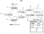
図1は第一の実施例のセンサネットシステムのシステム構成の全体を表す。センサネットシステムは、センサノードの制御や関連付けなどの管理を行うミドルウェアが搭載されている管理サーバ4、複数の基地局1、複数の中継機2および複数のセンサノード3から構成されている。基地局4と中継機2とセンサノード3は無線で接続されており、 パーソナル・エリア・ネットワーク(Personal Area Network、PAN)を構築している。基地局1と管理サーバ4はイーサ(Ether)ないしユーエスビー(Universal Serial Bus、 USB)などにより接続されている。
FIG. 1 shows the entire system configuration of the sensor network system of the first embodiment. The sensor network system includes a
図2は図1のセンサネットシステムで用いられるセンサノード3のハードウェア構成の一具体例を示した図である。
FIG. 2 is a diagram showing a specific example of the hardware configuration of the
センサノード3は無線送受信を行う無線送受信部(RF Transceiver)201、表示部(Display)202、ボタン(Button)203、センサ(Sensor(s))204、処理部であるマイコン(MicroProcessor)205、絶対時刻を持つリアル・タイム・クロック(Real-time Clock)206、記憶部である揮発性メモリ(Volatile Memory)207と不揮発性メモリ(Nonvolatile Memory)208と読み出し専用メモリ(Read-Only Memory)209、及びノードの各部に電力を供給するバッテリ(Battery)210とから構成される。
The
センサノード3は、そのハードウェアにおいてReal-Time Clock206以外の電源をOFF状態にする休眠状態と、全ての回路の電源をON状態にする起動状態の2つの動作を一定周期ごとに使い分ける。センサノード3は起動状態において、様々なセンサSensor(s)204を用いてセンシングを行う。センシングされた情報はReal-Time Clock206の時刻情報と共にMicroProcessor205にてパケットに格納され、RF Transceiver201から基地局及び中継機に無線で送信されると共に、Nonvolatile Memory208へ格納される。
The
操作ボタンButton203は、ユーザの操作を受け付ける入力デバイスであり、特定のボタン操作により、センサノード3の特定の動作を起動したり、動作パラメータを設定したりすることができる。
The
表示部Display202は、ユーザに対して情報を表示するための出力デバイスである。例えば、センサノード3が環境計測用に室内または室外に設置する用途である場合には、センサ部Sensor(s)204により計測した最新の測定値を表示することができる。その際、低電力化のために、通常時は何も表示せず、特定のボタン操作を行った時のみ、該最新測定値を表示するといった活用が好適である。また、センサノード3が名札型や腕時計型等の携帯センサノードである場合には、通常時は時刻情報を表示し、管理サーバ4からテキストメッセージを受信した場合には該メッセージを表示したり、音声メッセージを受信した際には該着信情報を表示したりするといった活用が好適である。また、ユーザのボタン操作に連動して、階層化された操作メニューを表示することができる。該操作メニューに従ってボタン操作を行うことにより、アプリケーションユーザ(Application User)やシステム管理者(System Manager)は、センサノードの動作パラメータを設定したり、通信失敗時のエラー情報を確認したりすることができる。
The
図3は図1のセンサネットシステムの中継機2のハードウェア構成の一具体例を示した図である。中継機は無線送受信を行う無線送受信部(RF Transceiver)301、表示部(Display)302、ボタン(Button)303、センサ(Sensor(s))304、マイコン(MicroProcessor)305、絶対時刻を持つリアル・タイム・クロック(Real-time Clock)306、揮発性メモリ(Volatile Memory)307、不揮発性メモリ(Nonvolatile Memory)308、読み出し専用メモリ(Read-Only Memory)309とから構成される。
FIG. 3 is a diagram showing a specific example of the hardware configuration of the
中継機は揮発性メモリ307に記憶された時刻設定要管理テーブル311を用いて配下のセンサノードに対する経路を把握している。基地局から無線で配信されたセンサノードへのコマンドをRF Transceiver301にて受信し、テーブル311に存在するセンサノードに対し無線で配送する。また、センサノードから無線で送信されたセンシング情報を受信し、受信したセンシング情報を基地局へ無線で送信する。
The repeater uses the time setting necessity management table 311 stored in the
中継機RT1は、いつ送信されてくるか分からない、センサノードや基地局からのデータを常時待ち受けていなければならないので、センサノードと異なり、バッテリではなく外部給電により動作する。電源線(Power Line)より供給される電力を、電源回路(Power Supply Circuit)310により整流等を行った上で各機能部へ供給する。
The relay RT1 must always wait for data from a sensor node or a base station, which does not know when it will be transmitted, and therefore operates by external power supply instead of a battery, unlike the sensor node. Power supplied from a power line is rectified by a
消費電力の心配をする必要がないため、中継機2のマイコン305はセンサノード3の場合のように休眠状態に入る必要はない。そのため割り込み制御部(Interrupt Controllerやタイマ部(Timer)は図中では省略してあるが、これらの機能は一般的なデータ送受信アルゴリズムの範囲内で活用される。
Since there is no need to worry about power consumption, the
図4は図1のセンサネットシステムにおける基地局1のハードウェア構成の一具体例を示した図である。
FIG. 4 is a diagram showing a specific example of the hardware configuration of the
基地局は、IPネットワーク(IP Network)を介して管理サーバ(Middleware Server)4と通信を行うためのLAN通信インタフェース(LAN I/F)412を備える以外は、中継機2の構成と同様であるため、説明を省略する。なお、同図において、数番401〜410は図3における数番301〜310に対応する。なお、揮発性メモリ407中には後述するバインディング・テーブル(Binding Table)411が記憶される。
The base station has the same configuration as the
図5は図1のセンサネットシステムの管理サーバ4のハードウェア構成の一具体例を示したブロック図である。
FIG. 5 is a block diagram showing a specific example of the hardware configuration of the
センサネット管理サーバ4は、処理部(CPU)501、外部通信部502、電源503、ハードディスクドライブ504、ユーザからの命令をするための入力装置であるキーボード505、表示装置であるディスプレイ506、メモリ507からなる。
The sensor
センサネット管理サーバ4は、外部通信部502を経由し、基地局1が中継機2を介してセンサノード1から収集したデータの受信、および基地局1へコマンドの送信を行う。CPU501はメモリ507に記憶されたミドルウェア等のプログラムを読み込み、プログラムの指示に従って通信部502を通じて取得した観測値などのデータの加工を行い、ハードディスクドライブ504へデータを蓄積したり、ディスプレイ506に表示したりする。この管理サーバ4で実行される加工・表示の具体例は後で詳述する。またCPU501は、キーボード505から入力されたユーザコマンドの解釈を行い、通信部502を通じて基地局1へと配信する。
The sensor
次に、図6は本実施例におけるセンサノード3の機能を示すブロック図である。
Next, FIG. 6 is a block diagram showing the function of the
センサノード3の機能は、時刻を管理するReal-Time Clock206と、観測や観測値蓄積やイベント発行やPolling発行を管理するMain部601と、センサを用いて観測を行う観測部602と、観測値などのイベントを発行するイベント発行部604と、親中継機2ないし親基地局1に対しコマンドの有無の確認であるPollingの発行を行うPolling発行部605と、イベントないしPollingの送信を行う送信部606と、観測値の蓄積を管理する観測値蓄積管理部(イベント蓄積部)607と、観測値を蓄積し観測値テーブル613により管理する観測値蓄積部603と、観測値テーブル613内の時刻未確定フラグがONの観測値に対してタイムスタンプの補正を行う観測値タイムスタンプ補正部608と、Real-Time Clockの設定ないし修正を行うRTC設定部609と、親中継機ないし親基地局よりコマンドを受信する受信部610と、受信したコマンドを解析するコマンド解析部611と、時刻設定以外のコマンドを処理する他コマンド処理部612とがある。
The function of
観測値蓄積部603に蓄積される観測値テーブル613には、観測値の通し番号であるシーケンス番号614と、観測値が時刻設定済みか否かを記憶している時刻未確定フラグ615と、観測値616と、該観測値の時刻617が保存される。なお、図2に示したセンサノード3のハードウェア構成上、観測値蓄積部603は不揮発性メモリ203に形成される。
In the observation value table 613 accumulated in the observation
また、図6の送信部606、受信部610は図2におけるRF Transceiver201に相当する。その他Main部601、観測部602、イベント発行部604〜RTC設定部609、コマンド解析部611、及び他コマンド処理部612は、図2のMicroProcessor205において実行されるプログラム機能であり、通常これらのプログラムはROM209などの記憶部に記憶されている。
Also, the
図7は本実施例における中継機2の機能を示すブロック図である。
FIG. 7 is a block diagram showing the function of the
中継機2はコマンド受信部701、時刻設定処理部1101、コマンド送信処理部1401、コマンド要求受信部707、コマンド発行部708、コマンド発行部708、Real-Time Clock206からなる。また、時刻設定処理部1301は、時刻設定要ノード管理部703および時刻設定管理部702がある。コマンド送信処理部1401には、時刻設定状況確認部706、および時刻取得部705がある。また、図3のVolatile Memory307に時刻設定要ノード管理テーブル311を持つ。この時刻設定要ノード管理テーブル311には、センサノード毎に別々に割り振られるセンサノードID709と、ノードID709のセンサノードが時刻設定済みか否かを判定するための時刻設定要フラグ710が保存される。
The
中継機2は管理サーバ4から配送されたコマンドを、コマンド受信部701にて受信する。受信したコマンドが時刻合わせ(setTime)コマンドの場合に、Real-time Clock306の時刻を設定あるいは修正を行う時刻設定部702、時刻設定要ノード管理テーブル311に登録されているセンサノードの時刻設定要フラグをONにする時刻設定要ノード管理部703が機能する。
The
また、センサノード3からのPollingは、コマンド要求受信部707にて受信する。時刻設定状況確認部706は、時刻設定要ノード管理テーブル311内のセンサノードからPollingを受信した際、当該センサノードの時刻設定要フラグ710を確認する。時刻取得部705は、Real-Time Clock306から時刻を取得する。コマンド発行部708は、センサノード3へコマンドを発行する。これらの機能は、例えば図3に示したMicroProcessor305で順次実行されるプログラムであることは言うまでもなく、以下同様である。
Polling from the
図8は本実施例における基地局1の機能を示すブロック図である。
FIG. 8 is a block diagram showing functions of the
基地局1の機能は、管理サーバ4と通信を行う有線通信部801と、管理サーバ4からのコマンドの処理を行うコマンド処理部805と、基地局1のReal-Time Clock806を設定するための時刻設定部806と、setTimeコマンドを受信した際にBindingTable411を参照し、setTimeコマンドを処理するためのsetTime処理部807と、BindingTable411に存在する配下の中継機2ないしセンサノード3に対しコマンドを発行するコマンド発行部804と、中継機2ないしセンサノード4と無線通信を行う無線通信部803と、中継機2ないしセンサノード4から受信したイベントの処理を行うイベント処理部802とからなる。BindingTable808は、登録されているノードが中継機かセンサノードかを記憶していく種類記憶域809と、ノード毎に個別に与えられるノードID810が保存されている。
The functions of the
図9は本実施例におけるセンサネット管理サーバ4のネット管理機能を示すブロック図である。
FIG. 9 is a block diagram showing the network management function of the sensor
管理サーバ4のネット管理機能は、時刻設定管理部902と、ユーザコマンド910を受信し時刻設定管理部902やコマンド作成部(Action Manager)906に伝達するためや外部へ返戻を送信を行う外部要求受付部901と、NTP(Network Time Protocol)などの基準時刻903と同期を取り任意の時間毎にsetTimeコマンドを発行するよう管理を行うタイマ904と、setTimeコマンドの発行を行う時刻合わせ(setTime)コマンド発行部905と、基地局1との通信を行う通信部502に該当するセンサネット通信部907(Profiled Adapter & ZigBee Adapter)と、基地局1ないし中継機2ないしセンサノード3からのイベントの配送を行うイベント配送部(Event Publisher)908と、センサノード3の観測値を保存する観測値蓄積部909とからなる。この観測蓄積部908は、図5のおけるハードディスクドライブ504やメモリ507などの記憶部に形成されることは言うまでもなく、この蓄積部909と通信部907を除いた機能は、図5に示した処理部(CPU)501の処理機能として構成される。
The network management function of the
続いて、本実施例のセンサネットシステムにおいて、各装置の構成・機能を用いてシステム全体の時刻同期を取る動作について説明する。 Subsequently, in the sensor network system of the present embodiment, an operation for synchronizing the time of the entire system using the configuration and function of each device will be described.
図10はセンサノード3(センサ#1)が10分間を周期とする間欠動作を行う際の、中継機2・センサノード(センサ#1)3間の時刻設定シーケンス図である。なお、本図は時刻設定シーケンスを表す図のため、観測など時刻設定以外の動作は省略している。
FIG. 10 is a time setting sequence diagram between the
さて、センサ#1が休眠期間1012から復帰し起動期間1006に入ると、センサ#1は親中継機2に対してPolling1007を行う。この時点では中継機2はsetTimeを受信しておらず、時刻設定要ノード管理テーブル311内の時刻設定要フラグ710がOFF(同図でホワイト表示)のため、中継機がセンサ#1に対し、Polling1007の応答としてコマンド無し1008を送信する。該応答を受信したセンサ#1は直ちに休眠期間1013に移行する。ここで、起動期間1006の長さは、Pollingと応答の受信を含めても数ミリ秒から数10ミリ秒程度である。
Now, when the
その後、中継機2は、管理サーバ4が発行する基準時刻1001を取得すると、該中継機自身のReal-time Clock306を設定ないし修正し、時刻設定要ノード管理テーブル311に登録されている配下のセンサノード3の時刻設定要フラグ710をON(同図でグレー表示)にする。中継器2は、時刻設定要ノード管理テーブル311に登録されている配下のセンサノード(センサ#1)から、コマンド要求であるPolling1007を受信した際、時刻設定要フラグ710を確認し、該フラグがONの時はコマンド有り1009を返戻し、且、該中継機自身のReal-time Clock306より時刻を取得し(S1006)、該センサ#1へとsetTimeコマンド1010として取得した時刻(T2)を配送する。その後、中継機3は該センサノードの該時刻設定要フラグ710をOFFにする。該センサ#1は、コマンド有り1009の返戻を受け取ると、しばらく受信待ち状態を維持し、受信した時刻(T2)を基に該センサノード自身のReal-Time Clock206の時刻を修正する。このとき、センサ#1の起動期間1014は、setTimeコマンドを受信し時刻設定を行うため起動期間1006より長くなるが、合計で10ミリ秒から50ミリ秒程度と、休眠期間の長さである10分間と比較すると一瞬である。
After that, when the
図11は管理サーバ4と基地局1と中継機2と2台のセンサノード3との間の時刻設定シーケンス図である。なお、センサノード3が3台以上の場合も同様なシーケンスとなる。
FIG. 11 is a time setting sequence diagram among the
まず、センサ#1が休眠期間1106から復帰し起動期間1107に入ると、センサ#1は親中継機2に対してPolling1007を行う。この時点では中継機2はsetTimeを受信しておらず、時刻設定要ノード管理テーブル1111内の時刻設定要フラグ710が全てOFFのため、中継機2がセンサ#1に対しPolling1007の応答としてコマンド無し1008を送信する。該応答を受信したセンサ#1は直ちに休眠期間1108に移行する。ここで、起動期間1107の長さは、Pollingと応答の受信を含めても数ミリ秒から数10ミリ秒程度である。センサ#2も同様に、復帰後に起動期間1111に入ると、親中継機2に対してPolling1103を行う。中継機は、センサ#1同様にコマンド無し1104を返戻し、該返戻を受信したセンサ#2は直ちに休眠期間1112へと移行する。
First, when the
管理サーバ4は上述の通り、NTPにより基準時刻と同期を行っている。管理サーバは定期的、あるいはユーザが指定したタイミングにおいて基地局1に対しsetTimeコマンドとして時刻(T1)を送信する。該基地局1は、受信した時刻(T1)を用いて自身のReal-Time Clock406を設定ないし修正する(1101)。該基地局3は、Real-Time Clock設定1101と同時に、該基地局が通信可能なノードの管理テーブルであるBindingTable808を確認し、該テーブルに登録されている配下の中継機に対しsetTimeコマンドとして管理サーバ4から取得した時刻(T1)を送信する。図11では中継機2を1つしか記載していないが、テーブルに登録されている中継機が複数ある場合は、全ての中継機に同じように時刻(T1)を送信することにより、時刻同期を行なう。
As described above, the
中継機2は、前記基地局から受信した時刻(T1)を基に該中継機自身のReal-Time Clock306を設定ないし修正し(1301)、時刻設定要ノード管理テーブル311に登録されている配下の全てのセンサノードに対し、時刻設定要フラグ710をONにする。センサノード3a(センサ#1)は、休眠期間1108から復帰後にただちに観測(1102)を行い、親中継2に対しコマンド要求であるPolling1107を行う。センサ#1の親中継機2は、時刻設定要ノード管理テーブル311に登録されている配下のセンサノードから、コマンド要求であるPolling1107を受信すると、該センサノードの時刻設定要フラグ710を確認し、該フラグがONの時はコマンド有り1009を返戻し、且、該中継機2自身のReal-Time Clock306より時刻を取得し(S1406)、setTimeコマンドとして時刻(T2)を送信する。その後、該センサ#1からsetTimeコマンド応答であるAckを受信すると、該センサノードの時刻設定要フラグ710をOFFにする。このとき、センサ#1の起動期間1109は、setTimeコマンドを受信し時刻設定を行うため起動期間1107より長くなるが、Pollingと時刻設定受信とObservedイベント送信(1105)と返戻(Ack)の受信を行う処理時間の合計で10ミリ秒から50ミリ秒程度と、休眠期間の長さである10分間と比較すると一瞬である。
The
センサノード3b(センサ#1)は、コマンド有り1009の返戻を受け取ると、しばらく受信待ち状態を維持し、受信した時刻(T2)を基に該センサノード自身のReal-Time Clock206の時刻を修正する。該センサ#1は、自身のReal-Time Clock206から時刻を取得し、観測値に付与しObservedイベント(1105)として中継機2に送信する。センサノード3b(センサ#2)に関しても、センサ#1の時刻設定シーケンスと同様のシーケンスである。
When the
なお、図11には示していないが、基地局1に直接センサノード3が複数接続されている場合もあり得る。その場合は、基地局1とセンサノード3間のシーケンスは、中継機2とセンサノード3間のシーケンスにおいて中継機2を基地局1に置き換えたシーケンスで、基地局1とセンサノード3がそれぞれ同様に振舞うことは言うまでもない。
Although not shown in FIG. 11, a plurality of
続いて、図12に本実施例における中継機2の動作PAD図を示す。
Next, FIG. 12 shows an operation PAD diagram of the
中継機2は、受信したデータがセンサノード3からの観測値などのイベントの場合は基地局1へ転送を行うイベント転送1203と、センサノード3からのPollingの場合に行うコマンド送信1401と、基地局1からのsetTimeコマンドを受信した際に行う時刻設定処理1301と、時刻設定以外のコマンドを受信した際に行うコマンド蓄積処理1204とを行う。
The
図13は中継機2の時刻設定処理部1301における時刻設定処理シーケンスを表す図である。中継機2は管理サーバ4から基地局1を介してsetTimeコマンドをコマンド受信部701において受信する(ステップS1302)。そして、時刻設定部702はsetTimeコマンド内の時刻に、中継機自身のReal-Time Clock306を設定する(ステップS1303)。その後、時刻設定要ノード管理部703において時刻設定テーブル311にて管理されている配下の子ノードの時刻設定要フラグ710を全てONにし(ステップS1304)、終了する(ステップS1305)。
FIG. 13 is a diagram illustrating a time setting processing sequence in the time setting
図14は中継機2のコマンド送信シーケンスを表す図である。中継機2は、センサノード3からコマンド要求であるPollingをコマンド要求受信部707にて受信すると、蓄積しているコマンドが存在するかを判定し(S1402)、コマンドが存在する場合はセンサノードに対しコマンド有りを送信する(ステップS1404)。その後、時刻設定状況確認部706において時刻設定要ノード管理テーブル311の該センサノードの時刻設定要フラグ710を確認し(ステップS1405)、該フラグがONの場合は時刻取得部705において中継機2のReal-Time Clock306より現在時刻を取得し(ステップS1406)、コマンド発行部708よりsetTimeコマンドを送信し(S1407)、該センサノードの時刻設定要フラグをOFFにし(ステップS1408)、他の蓄積しているコマンドがあるかを確認する(S1402)。時刻設定要フラグ710がOFFの場合、蓄積されている他のコマンドを送信し(S1409)、更に他の蓄積しているコマンドがあるかを確認する(S1402)。該センサノードに対する蓄積しているコマンドが無い場合、該センサノードに対しコマンド無しを送信(S1403)し、終了する(S1410)。
FIG. 14 is a diagram illustrating a command transmission sequence of the
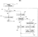
図15は本実施例におけるセンサノード3の動作フローチャートである。
FIG. 15 is an operation flowchart of the
センサノード3は一定間隔で起動状態に入る起動(S1501)と休眠状態に入る休眠(S1514)を繰り返す間欠動作を行っている。この起動間隔はセンサノードに複数のセンサ204が搭載されている場合、センサ毎に個別の間隔を設定することができる。センサノード3は起動すると図6に示した観測部602において観測(S1502)を行い、Polling発行部605よりPollingを発行し、親中継機2に対して送信部606よりPollingを送信する(S1503)。中継機2からの返戻を受信部610で受信し、コマンド有りか無しかの判断を行い(S1504)、コマンドが有りの場合は該コマンドを受信する(S1505)。コマンド解析部611において受信した該コマンドがsetTimeコマンドか否かを判定し(S1506)、setTimeコマンドの場合はRTC設定部609において自身のReal-Time Clock206の設定ないし修正を行い(S1507)、観測値テーブル613内の過去の観測値のうち、時刻未確定フラグがONの観測値のタイムスタンプを観測値タイムスタンプ補正部608にて補正する(S1508)。受信した該コマンドがsetTimeコマンドでは無い場合、他コマンド処理部612にて該コマンドの処理を行う(S1509)。
The
コマンドの処理を終えると、センサノード3は自身が時刻設定済みであるかを判定し(S1510)、時刻設定済みである場合、現在時刻を観測値にタイムスタンプとして付与したイベントをイベント発行部604より発行し、送信部606より観測イベントを親中継機2ないし親基地局1へと送信する(S1512)。センサノード3が時刻設定済みでない場合においては、観測値は送信しないが、センサノード3の生存を知らせるため、親中継機2ないし親基地局1へHeartBeatイベントを送信する(S1511)。
When the command processing is completed, the
イベント送信後、センサノード3は観測値をシーケンス番号、時刻未確定フラグ、Real-Time Clockの時刻と共にメモリに蓄積し(S1513)、休眠する(S1514)。
After transmitting the event, the
図16は、上述した図15におけるセンサノード3の観測値テーブル613のタイムスタンプ補正(S1508)を説明するための図である。同図(a)、(b)はそれぞれタイムスタンプ補正前後のセンサノード3中の観測値テーブル613内のデータの一例を示している。
FIG. 16 is a diagram for explaining the time stamp correction (S1508) of the observation value table 613 of the
センサノード3は、親中継機2ないし親基地局1からsetTimeコマンドを受信し時刻設定を行ったタイミングで、最新の観測値のタイムスタンプとsetTimeコマンドの時刻の差分を算出する。その後、該センサノードの観測値テーブル613を参照し、時刻未確定フラグがONの観測値のタイムスタンプに、この差分を足し合わせることにより時刻を修正し、該時刻未確定フラグをOFFにすることで、観測値のタイムスタンプを補正する。
The
前述の差分は、setTimeコマンド内の時刻と、setTimeコマンドを受信した時点でのReal-Time Clock206補正前の時刻との差分でも良い。また、タイムスタンプの補正のタイミングは、この差分の計算後、任意のタイミングで行うことができる。
The difference described above may be a difference between the time in the setTime command and the time before correction of the Real-
なお、センサノード3の送信部606より親中継機2ないし親基地局1へ送信された観測値データを含む観測イベントは、全て管理サーバ4に送信され、図5、図9の記憶部中の観測値蓄積部909に蓄積され、後でその具体例を詳述するように、適宜加工処理される。
Note that all observation events including observation value data transmitted from the
次に第二の実施例として、図17に示す他の時刻同期方式を採用するセンサネットシステムを説明する。 Next, as a second embodiment, a sensor network system employing another time synchronization method shown in FIG. 17 will be described.
図17はセンサノード3(センサ)が基地局1へと直接接続している際に、センサノード3が要求したタイミングで時刻同期を実施するセンサノード主導型時刻設定シーケンスを示している。センサノード3は基地局1と接続時、あるいは定期的に基地局1に対し時刻設定要求(1701)を送信する。基地局1は該時刻設定要求の応答(Ack)1702を送信すると同時に、基準時刻情報を取得する(1703)。該基地局が該時刻設定要求を受信してから該時刻情報の取得に要する時間は、1ミリ秒程度である。
FIG. 17 shows a sensor node initiative time setting sequence in which time synchronization is performed at a timing requested by the
センサノード3は該時刻設定要求への応答(Ack)を受信した時点で内部のタイマを起動する(1704)。基地局1が該応答を送信し、センサノード3が受信を行うまでの処理時間は1ミリ程度であるため、基地局1が時刻設定要求を受信し時刻を設定するのに要した時間と近似的に同じと見なすことができる。
The
ここで、タイマとはセンサノード3の内部のマイコンに内蔵されているタイマで、例えばルネサステクノロジ社のH8S/2215の場合、時間精度は1ppmであるため、時刻設定による誤差は無視できる。しかし、割り込みにより時刻設定以外の処理を行う必要があるため、時間精度は10ミリ秒である。なお。休眠期間においては、マイコンは低電力モードで休眠しているが、タイマ動作は実行される。
Here, the timer is a timer built in the microcomputer inside the
そして、センサノード3は次に起動した際にコマンド要求であるPollingコマンドを送信(1704)すると、基地局1は応答として、第2のsetTimeコマンドとして取得した時刻をセンサノード3に送信する(1705)。該センサノード3は該基地局1からの第2のsetTimeコマンドを受信した時点でタイマを停止し(1708)、第2のsetTimeコマンドと同時に受信した時刻にタイマにて計測した時間を足した時刻を、現在時刻として自分自身の時計であるReal-Time Clock206に設定する(1709)。
Then, when the
この時刻設定により、基地局1と時刻同期した各センサノード3は、第一の実施例の図11に示したと同様、蓄積した観測値を観測イベントとして直接、基地局1へ送信するが、説明が重複するためここでは省略する。
By this time setting, each
図18は、上述してきた時刻同期方式に基づくセンサノードシステムを用い、管理サーバ4が、その観測値蓄積部909にて蓄積した観測値データを用い、センサノードを装着する複数の人物間の影響力を求める応用システムの機能を説明する図である。図18(a)に示すように、2人以上の人物1801と人物1802が、センサノード3aと3bを所持・装着しているとする。例えば、人物1801と人物1802が対話中に人物1801の重要な発話に同意して、人物1802が首を縦に振ることや、人物1801の発話に同意してうなり声を上げる、発言を書き留めるといった何かしらのジェスチャを行うことは、人物1802は人物1801の影響を受けていると言える。また、相手が近づいてきたら立ち去るという、負の影響もある。これらの動作や発話はランダムではなく、図18(c)のブロック1803に示す通り、人物1801の加速度ないし音声の観測値波形による発話や動作の観測から1秒以内の遅延をして、人物1802の加速度ないし音声の観測値波形に現れる。
FIG. 18 shows the influence between a plurality of persons wearing sensor nodes using the observation value data accumulated in the observation
このことから、図18(b)のセンサノード3間において、例えば100ms精度で同期されたセンサノード3a、3bのセンサ信号から対話者同士の時間軸における動作の相関を求めることにより、対話者同士の意思疎通を求めることができるため、センサノード3間の同期された観測値が重要となり、この同期方式として上述した時刻同期方式が採用される。よって、以下の応用システムの説明においては、上述した時刻同期方式が採用され、各センサノードは必要な精度の時刻同期を取ることとなる。
From this, between the
図19a、図19b、図19cは、本応用システムにおいて意思疎通を求める処理を実行し、組織ダイナミクス解析を実行する処理の全体の流れを示す説明図である。 FIG. 19a, FIG. 19b, and FIG. 19c are explanatory diagrams showing the overall flow of processing for executing communication dynamics analysis and executing processing for obtaining communication in this application system.
具体的には、図19a、図19b、図19cは、複数のセンサノード3による組織ダイナミクスデータの取得から、組織アクティビティとして人物間の関係性と現在の組織の評価(パフォーマンス)を図示するまでの一連の流れを示す。
Specifically, FIG. 19a, FIG. 19b, and FIG. 19c show the relationship between the acquisition of organization dynamics data by a plurality of
本実施例では、組織ダイナミクスデータ取得(BMA)、パフォーマンス入力(BMP)、組織ダイナミクスデータ収集(BMB)、相互データ整列(BMC)、相関係数の学習(BMD)、組織アクティビティ解析(BME)及び組織アクティビティ表示(BMF)の各処理が適切な順序で実行される。 In this example, tissue dynamics data acquisition (BMA), performance input (BMP), tissue dynamics data collection (BMB), mutual data alignment (BMC), correlation coefficient learning (BMD), tissue activity analysis (BME) and Each process of the organization activity display (BMF) is executed in an appropriate order.
まず、組織ダイナミクスデータ取得(BMA)について説明する。図19cに示すセンサノード3A(TRa)は、加速度センサ(TRAC)、赤外線送受信器(TRIR)、マイクロホン(TRMI)等のセンサ類、マイクロコンピュータ(図示省略)及び無線送信機能を有する。センサ類は、種々の物理量を検出し、検出された物理量を示す観測値データを取得する。例えば、加速度センサ(TRAC)は、センサノード3A(TRa)の加速度(すなわち、センサノード3A(TRa)を装着している人物A(図示省略)の加速度)を検出する。赤外線送受信器(TRIR)は、センサノード3A(TRa)の対面状態(すなわち、センサノード3A(TRa)が他のセンサノード3と対面している状態)を検出する。なお、センサノード3A(TRa)が他のセンサノード3と対面していることは、センサノード3A(TRa)を装着した人物Aが、他のセンサノード3を装着した人物と対面していることを示す。マイクロホン(TRMI)は、センサノード3A(TRa)の周囲の音声を検出する。センサノード3A(TRa)は、上記以外のセンサ(例えば、温度センサ、照度センサ等)を備えてもよい。
First, tissue dynamics data acquisition (BMA) will be described. A sensor node 3A (TRa) shown in FIG. 19c has sensors such as an acceleration sensor (TRAC), an infrared transceiver (TRIR), a microphone (TRMI), a microcomputer (not shown), and a wireless transmission function. The sensors detect various physical quantities and obtain observation value data indicating the detected physical quantities. For example, the acceleration sensor (TRAC) detects the acceleration of the sensor node 3A (TRa) (that is, the acceleration of the person A (not shown) wearing the sensor node 3A (TRa)). The infrared transmitter / receiver (TRIR) detects the facing state of the sensor node 3A (TRa) (that is, the state where the sensor node 3A (TRa) is facing another sensor node 3). The sensor node 3A (TRa) faces another
本応用例のシステムは、複数のセンサノード3(図19cのセンサノード3A(TRa)〜センサノード3J(TRj)を備える。各センサノード3は、それぞれ、一人の人物に装着される。例えば、センサノード3A(TRa)は人物Aに、センサノード3B(TRb)は人物B(図示省略)に装着される。各センサノードを装着する人物(装着者)間の関係性を解析し、さらに、組織のパフォーマンスを図示するためである。
The system of this application example includes a plurality of sensor nodes 3 (sensor nodes 3A (TRa) to 3J (TRj) in FIG. 19c. Each
なお、センサノード3B(TRb)〜センサノード3J(TRj)も、センサノード3A(TRa)と同様、センサ類、マイクロコンピュータ及び無線送信機能を備える。以下の説明において、センサノード3A(TRa)〜センサノード3J(TRj)のいずれにも当てはまる説明をする場合、及び、それらのセンサノード3を特に区別する必要がない場合、センサノード3(TR)と記載する。
Note that the sensor node 3B (TRb) to the sensor node 3J (TRj) also have sensors, a microcomputer, and a wireless transmission function, like the sensor node 3A (TRa). In the following description, when a description that applies to any of sensor node 3A (TRa) to sensor node 3J (TRj) is given, and when it is not necessary to distinguish between these
各センサノード3(TR)は、常時(又は短い間隔で繰り返し)センサ類によるセンシングを実行する。そして、各センサノード3(TR)は、取得したデータ(センシングデータ)を、所定の間隔で無線によって送信する。データを送信する間隔は、センシング間隔と同じであってもよいし、センシング間隔より大きい間隔であってもよい。このとき送信されるデータには、センシングした時刻と、センシングしたセンサノード3(TR)の固有のIDが付与されている。データの無線送信をまとめて実行するのは、送信による電力消費を抑えることによって、人が装着したままで、センサノード3(TR)の使用可能状態を長時間維持するためである。また、全てのセンサノード3(TR)において同一のセンシング間隔が設定されていることが、後の解析のためには望ましい。 Each sensor node 3 (TR) performs sensing by sensors at all times (or repeatedly at short intervals). Each sensor node 3 (TR) transmits the acquired data (sensing data) wirelessly at a predetermined interval. The interval at which data is transmitted may be the same as the sensing interval or may be larger than the sensing interval. The data transmitted at this time is given a sensing time and a unique ID of the sensed sensor node 3 (TR). The reason why the wireless transmission of data is collectively performed is to maintain the usable state of the sensor node 3 (TR) for a long time while being worn by a person by suppressing the power consumption by the transmission. In addition, it is desirable for the later analysis that the same sensing interval is set in all the sensor nodes 3 (TR).
図19cに示すパフォーマンス入力(BMP)は、パフォーマンスを示す値を入力する処理である。ここで、パフォーマンスとは、何らかの基準に基づいて判定される主観的又は客観的な評価である。例えば、所定のタイミングで、センサノード3(TR)を装着した人物は、その時点における業務の達成度、組織に対する貢献度及び満足度等、何らかの基準に基づく主観的な評価(パフォーマンス)の値を入力する。所定のタイミングとは、例えば、数時間に一度、一日に一度、又は、会議等のイベントが終了した時点であってもよい。センサノード3(TR)を装着した人物は、そのセンサノード3(TR)を操作して、又は、クライアント(CL)のようなPC(Personal Computer)を操作して、パフォーマンスの値を入力することができる。あるいは、手書きで記入された値が後にまとめてPCで入力されてもよい。なお、入力されたパフォーマンス値は、相関係数を学習するために用いられる。このため、ある程度の学習を行うために十分な量のパフォーマンス値が取得できていれば、必ずしもさらに値を入力する必要はない。 The performance input (BMP) shown in FIG. 19c is a process for inputting a value indicating performance. Here, the performance is a subjective or objective evaluation determined based on some criterion. For example, a person wearing sensor node 3 (TR) at a predetermined timing has a subjective evaluation (performance) value based on some criteria such as the degree of achievement of business, the degree of contribution to the organization, and the degree of satisfaction. input. The predetermined timing may be, for example, once every several hours, once a day, or when an event such as a meeting ends. The person wearing the sensor node 3 (TR) operates the sensor node 3 (TR) or operates a PC (Personal Computer) such as a client (CL) and inputs a performance value. Can do. Alternatively, values entered by handwriting may be collectively input later on a PC. The input performance value is used for learning the correlation coefficient. For this reason, it is not always necessary to input a value if a sufficient amount of performance value is obtained for performing a certain amount of learning.
組織に関するパフォーマンスは、個人のパフォーマンスから算出されてもよい。売上高又はコスト等の客観的なデータ、及び、顧客のアンケート結果等の既に数値化されているデータが、パフォーマンスとして定期的に入力されてもよい。生産管理等におけるエラー発生率等のように、自動で数値が得られる場合、得られた数値が自動的にパフォーマンスの値として入力されてもよい。 Organizational performance may be calculated from individual performance. Objective data such as sales or cost, and already digitized data such as customer questionnaire results may be periodically input as performance. When a numerical value is automatically obtained, such as an error occurrence rate in production management, the obtained numerical value may be automatically input as a performance value.
無線によって各センサノード3(TR)から送信されたデータは、図19cの組織ダイナミクスデータ収集(BMB)において収集され、データベースに格納される。例えば、センサノード3(TR)ごとに、言い換えるとセンサノード3(TR)を装着した人物ごとに、データテーブルが作成される。収集されたデータは、固有のIDに基づいて分類され、センシングされた時刻の順にデータテーブルに格納される。テーブルをセンサノード3(TR)ごとに作成しない場合、データテーブルの中にセンサノード3のID情報又は人物を示すカラムが必要になる。なお、図中のデータテーブルA(DTBa)は、データテーブルの例を簡略化して表現したものである。
The data transmitted from each sensor node 3 (TR) by radio is collected in the organization dynamics data collection (BMB) of FIG. 19c and stored in the database. For example, a data table is created for each sensor node 3 (TR), in other words, for each person wearing the sensor node 3 (TR). The collected data is classified based on the unique ID and stored in the data table in the order of the sensed time. When a table is not created for each sensor node 3 (TR), a column indicating ID information or a person of the
また、パフォーマンス入力(BMP)において入力されたパフォーマンスの値は、パフォーマンスデータベース(PDB)に時刻情報と共に格納される。なお、組織ダイナミクスデータ収集(BMB)で収集されるデータテーブル・データベースは、図5の記憶部に順次蓄積される。 The performance value input in the performance input (BMP) is stored together with time information in the performance database (PDB). Note that the data table / database collected by the organization dynamics data collection (BMB) is sequentially stored in the storage unit of FIG.
続いて、図19cに示す相互データ整列(BMC)では、任意の二人の人物に関するデータ(言い換えると、それらの人物が装着したセンサノード3(TR)が取得したデータ)を比較するために、時刻情報に基づいて二人の人物に関するデータが整列(アライアンス)される。整列されたデータは、テーブルに格納される。このとき、二人の人物に関するデータのうち、同じ時刻のデータが同じレコード(行)に格納される。同じ時刻のデータとは、同じ時刻に二つのセンサノード3(TR)によって検出された物理量を含む二つのデータである。二人の人物に関するデータが、同じの時刻のデータを含まない場合、最も近い時刻のデータが近似的に同じ時刻のデータとして使用されてもよい。この場合、最も近い時刻のデータが同じレコードに格納される。このとき、同じレコードに格納されたデータの時刻を、例えば、最も近い時刻の平均値によってそろえることが望ましい。なお、これらのデータは、時系列によるデータの比較ができるように格納されていればよく、必ずしもテーブルに格納されなくてもよい。 Subsequently, in the mutual data alignment (BMC) shown in FIG. 19c, in order to compare data about any two persons (in other words, data acquired by the sensor node 3 (TR) worn by those persons), Based on the time information, the data related to the two persons is aligned (alliance). The sorted data is stored in a table. At this time, the data at the same time among the data related to the two persons is stored in the same record (row). The data at the same time is two data including physical quantities detected by the two sensor nodes 3 (TR) at the same time. When the data regarding two persons does not include the data at the same time, the data at the closest time may be used approximately as the data at the same time. In this case, the data at the nearest time is stored in the same record. At this time, it is desirable to align the times of the data stored in the same record by, for example, the average value of the nearest times. Note that these data need only be stored so that the data can be compared in time series, and are not necessarily stored in the table.
なお、図19cの結合テーブル(CTBab)はデータテーブルA(DTBa)とデータテーブルB(DTBb)を結合したテーブルの例を簡略化して表現したものである。ただし、データテーブルB(DTBb)の詳細は、図示が省略されている。結合テーブル(CTBab)は、加速度、赤外線及び音声のデータを含む。しかし、データの種類ごとの結合テーブル、例えば、加速度データのみを含む結合テーブル、又は、音声のみの結合テーブルが作成されてもよい。 Note that the combined table (CTBab) in FIG. 19c is a simplified representation of an example of a table in which the data table A (DTBa) and the data table B (DTBb) are combined. However, details of the data table B (DTBb) are not shown. The combined table (CTBab) includes acceleration, infrared and audio data. However, a connection table for each type of data, for example, a connection table including only acceleration data or a connection table including only sound may be created.
続いて、本応用例では、組織ダイナミクスデータから関係性を計算したり、パフォーマンスを予測したりするために、相関係数の学習(BMD)を実行する(図19b参照)。 Subsequently, in this application example, learning of correlation coefficient (BMD) is executed in order to calculate the relationship from the organization dynamics data and to predict the performance (see FIG. 19b).
相関係数の学習(BMD)は、意思疎通を求める処理である。例えば、対話中に相手の重要な発話に対して、首を縦に振るなどの何かしらのジェスチャを行なう場合が多い。これらの動作はランダムではなく、あるタイミングに沿って行なっている。そのタイミングとは、相手の発話やジェスチャをした直後である。 Correlation coefficient learning (BMD) is a process for obtaining communication. For example, it is often the case that some gestures such as shaking the head vertically are performed on an important utterance of the other party during the conversation. These operations are not random, but are performed at a certain timing. The timing is immediately after the other person's speech or gesture.
このことから、センサノード3間において、同期された観測値であるセンサ信号から、センサノード装着者である対話者同士の時間軸における動作の相関を求めることにより、対話者同士の意思疎通を求めることができるため、センサノード3間の同期された観測値データが重要となること明らかである。
From this, between the
対話者1801がセンサノード3a(センサ#1)を、対話者1802がセンサノード3b(センサ#2)を所有している。この時、基地局1から前記2台のセンサノードのそれぞれに対しsetTimeコマンドを送付し、例えば10ミリ秒(ms)以下の誤差にて同期を行う。図18では対話者は2名であるが、対話者が複数人いる場合もあり得る。この場合、全ての対話者の中から全員を網羅する組みを指定し、それぞれの組みに対して処理を行う。
The
次に、図18のシステムを用いて相関係数の学習を行うための処理フローを図19bの相関係数の学習(BMD)に示す。このプロセスは、定期的に新規なデータを用いて計算し直すことによって相関係数を更新するとより効果的である。以下の説明は、加速度データから相関係数を算出する例である。しかし、加速度データの代わりに音声データ等の時系列データを用いても、同様の手順で相関係数を算出することができる。 Next, a processing flow for performing correlation coefficient learning using the system of FIG. 18 is shown in correlation coefficient learning (BMD) of FIG. 19B. This process is more effective if the correlation coefficient is updated by periodically recalculating with new data. The following description is an example of calculating a correlation coefficient from acceleration data. However, the correlation coefficient can be calculated in the same procedure even when time series data such as voice data is used instead of the acceleration data.
なお、本応用例では、図19bに示す相関係数の学習(BMD)は、先に図5、図9を用いて説明した管理サーバ4、特にその処理部(CPU)501によって実行される。しかし、実際には、相関係数の学習(BMD)は管理サーバ4以外の装置によって実行されてもよい。
In this application example, the correlation coefficient learning (BMD) shown in FIG. 19B is executed by the
始めに、管理サーバ4は、相関係数を計算するために用いるデータの幅Tを数日から数週間程度に設定し、その期間のデータを選択する。
First, the
次に、管理サーバ4は、加速度周波数計算(BMDA)を実行する。加速度周波数計算(BMDA)は、時系列に並んだ加速度データから周波数を求める処理である。周波数は、一秒間の波の振動数と定義され、つまり振動の激しさを表している指標である。しかし、正確な周波数を算出するにはフーリエ変換を行うことが必要であり、計算量に負担がかかる。フーリエ変換によって周波数を堅実に計算してもよいが、本応用例では、計算を簡略化するために、周波数に相当するものとして、ゼロクロス値を用いる。
Next, the
ゼロクロス値とは、一定の期間内における時系列データの値がゼロとなった回数、より正確には、時系列データが正の値から負の値へ、又は負の値から正の値へと変化した回数を計数したものである。例えば、加速度の値が正から負に変化してから、次にその値が再び正から負に変化するまでの期間を1周期とみなすと、計数されたゼロクロスの回数から、1秒間当たりの振動数を算出することができる。このようにして算出された一秒間当たりの振動数を、加速度の近似的な周波数として使用することができる。 The zero-cross value is the number of times the time-series data value becomes zero within a certain period, more precisely, the time-series data is changed from a positive value to a negative value, or from a negative value to a positive value. The number of changes is counted. For example, when the period from when the acceleration value changes from positive to negative until the value changes again from positive to negative is regarded as one cycle, the vibration per second is calculated from the counted number of zero crossings. A number can be calculated. The vibration frequency per second calculated in this way can be used as an approximate frequency of acceleration.
さらに、本応用例のセンサノード3(TR)は、三軸方向の加速度センサを備えているため、同じ期間の三軸方向のゼロクロス値を合計することによって一つのゼロクロス値が算出される。これによって、特に左右及び前後方向の細かい振り子運動を検出し、振動の激しさを表す指標として用いることができる。 Furthermore, since the sensor node 3 (TR) of this application example includes a triaxial acceleration sensor, one zero cross value is calculated by summing the zero cross values in the same triaxial direction. Thereby, in particular, a fine pendulum motion in the left-right and front-back directions can be detected and used as an index representing the intensity of vibration.
ゼロクロス値を計数する「一定の期間」として、連続したデータの間隔(つまり元のセンシング間隔)よりも大きな値が、秒又は分単位で設定される。 As a “certain period” for counting the zero-cross value, a value larger than a continuous data interval (that is, the original sensing interval) is set in units of seconds or minutes.
分析に用いる観測値は、対話者1801および対話者1802で同じ時間幅が望ましく、例えば、1日(24時間)がある。さらに、観測値は、連続ないし周期的に値が代入されていることが望ましく、もし観測値が欠損している場合には、欠損を示す値、例えばNULLを代入する。
The observation value used for the analysis preferably has the same time width for the
フレーム化処理(BMDB)では、観測値の時間幅を単一的な幅に分割する処理である。例えば、1日(24時間)分の観測値時間幅の場合には、1時間程度が良い。分割の幅のサイズをフレーム長という。入力センサ信号は複数のセンサ信号あるが、フレームの分割するタイミングと幅(フレーム長)は全て同じである。
また、フレームとフレームとの間隔を必ずしもフレーム分割した時間に合わせる必要はない。例えば、フレームとフレームとの区間(フレーム区間)を6分とした場合には、最初のフレームの開始時間と次のフレームの開始時間の間隔が6分ということを意味している。
In the framing process (BMDB), the time width of the observation value is divided into a single width. For example, in the case of observation time width for one day (24 hours), about one hour is good. The size of the division width is called the frame length. The input sensor signal has a plurality of sensor signals, but the timing and width (frame length) for dividing the frame are all the same.
Further, it is not always necessary to adjust the interval between frames to the time of frame division. For example, if the interval between frames (frame interval) is 6 minutes, it means that the interval between the start time of the first frame and the start time of the next frame is 6 minutes.
次に、入力観測値をフレーム毎に相互相関係数を求める(BMDC)。相互相関は2つのセンサ信号の時間変化の相互関係を表す。二つの観測値の相互相関係数は、 Next, the cross-correlation coefficient of the input observation value is obtained for each frame (BMDC). The cross-correlation represents the correlation between the time changes of the two sensor signals. The cross-correlation coefficient between the two observations is

さらに、相互相関係数を求める前に、相互相関係数の精度を高めるために、フレーム内に含まれる観測値の値をチェックする。相互相関処理に用いる同時期の2つのセンサ信号の両方とも欠損していない数を数え、欠損率を求め、欠損率が高いフレームの相互相関処理を行なわない。欠損率の閾値は別途指定することが可能である。 Further, before obtaining the cross-correlation coefficient, the value of the observed value included in the frame is checked in order to increase the accuracy of the cross-correlation coefficient. The number of missing two sensor signals at the same time used for the cross-correlation process is counted to obtain the defect rate, and the cross-correlation process is not performed for a frame with a high defect rate. The threshold for the defect rate can be specified separately.
最後に、相互相関係数では多数の値が出力されてしまうため、全体を俯瞰した値が必要となる。そこで、入力観測値におけるフレーム毎に求めた相互相関係数の平均を求めることで俯瞰処理BMDDを行い、相関Matrix(BMDE)を求める。次に、相関Matrix(BMDE)を用い、加速度データから6つのパフォーマンスが予測される。 Finally, since a large number of values are output in the cross-correlation coefficient, a value overlooking the whole is required. Therefore, the overhead processing BMDD is performed by obtaining the average of the cross-correlation coefficients obtained for each frame in the input observation value, and the correlation Matrix (BMDE) is obtained. Next, using the correlation Matrix (BMDE), six performances are predicted from the acceleration data.
図19aに示された組織アクティビティ解析(BME)は、結合テーブルにおける任意の二人の人物に関する加速度、音声、対面等のデータから人物間の関係性を求め、さらに組織のパフォーマンスを計算する処理である。この処理も、基本的は管理サーバ4、特にその処理部(CPU)501によって実行される。
The organization activity analysis (BME) shown in FIG. 19a is a process for obtaining the relationship between persons from data such as acceleration, voice, face-to-face, etc. regarding arbitrary two persons in the combined table, and further calculating the performance of the organization. is there. This processing is also basically executed by the
これによって、データを取得しながらリアルタイムで組織のパフォーマンスを予測してユーザに提示し、悪い予測であれば良い方向に行動を変化させるように促すことができる。つまり短いサイクルでフィードバックすることが可能になる。 Thereby, it is possible to predict the performance of the organization in real time while acquiring the data and present it to the user, and to prompt the user to change the behavior in a good direction if the prediction is bad. In other words, it is possible to feed back in a short cycle.
図19aを用い、まず、加速度データを用いた計算について説明する。加速度周波数計算(EA12)、個人特徴量抽出(EA13)、人物間の相互相関計算(EA14)及び組織特徴量計算(EA15)は、それぞれ、相関係数の学習(BMD)における加速度周波数計算(BMDA)、個人特徴量抽出(BMDB)、相互相関計算(BMDC)及び組織特徴量計算(BMDD)と同様の手順であるため、これらの説明を省略する。これらの手順によって、組織特徴量(x1、…、xm)が算出される。 First, calculation using acceleration data will be described with reference to FIG. 19a. Acceleration frequency calculation (EA12), individual feature amount extraction (EA13), cross-correlation calculation between persons (EA14), and tissue feature amount calculation (EA15) are respectively acceleration frequency calculation (BMDA) in correlation coefficient learning (BMD). ), Personal feature amount extraction (BMDB), cross-correlation calculation (BMDC), and tissue feature amount calculation (BMDD), and thus the description thereof is omitted. Through these procedures, tissue feature amounts (x1,..., Xm) are calculated.
そして、管理サーバ4は、ステップEA15において算出された組織特徴量(x1、…、xm)、及び、相関係数の学習(BMD)によって算出された各パフォーマンスに関する相関係数(A1、…、A6)を取得し(EA16)、これらを用いて各パフォーマンスの指標の値、
Then, the
![]()
![]()
後述するように、組織パフォーマンスを示す六つの指標の最新値が、バランス表示される。さらに、ある一つの指標の値の履歴が、指標予測履歴として時系列グラフとして表示される。 As will be described later, the latest values of the six indicators indicating the organizational performance are displayed in a balanced manner. Furthermore, the history of the value of a certain index is displayed as a time series graph as the index prediction history.
また、人物間の相互相関値から求められる任意の人物間の距離(EK41)は、組織構造を表示するためのパラメータ(組織構造パラメータ)を決定するために用いられる。ここで、人物間の距離とは、地理的な距離ではなく、人物間の関係性を示す指標である。例えば、人物間の関係が強い(例えば、人物間の相互相関が強い)ほど、人物間の距離が短くなる。また、人物間の距離に基づいてグループ化(EK42)を実行することによって、表示におけるグループが決定される。 In addition, the distance (EK41) between arbitrary persons obtained from the cross-correlation value between persons is used to determine a parameter (organization structure parameter) for displaying the organization structure. Here, the distance between persons is not a geographical distance but an index indicating the relationship between persons. For example, the stronger the relationship between persons (for example, the stronger the cross-correlation between persons), the shorter the distance between persons. Further, the group in the display is determined by performing grouping (EK42) based on the distance between the persons.
グループ化とは、特に密接な関係にある少なくとも二人の人物AとBを一組のグループとし、また別の密接な関係にある少なくとも二人の人物CとDを一組のグループとし、さらにそれらの人物A、B、C及びDを大きなグループとするように、密接な関係にある人物同士の組を作るための処理を指す。 Grouping is a group of at least two persons A and B that are particularly closely related, and a group of at least two persons C and D that are closely related, This refers to a process for creating a set of closely related persons so that these persons A, B, C, and D are in a large group.
なお、人物間の相互相関計算(EA14)から任意の人物間における関係性の距離を求め(EK41)、その距離を表示する方法の一例については後述する(図8参照)。 Note that an example of a method of obtaining a relationship distance between arbitrary persons from the cross-correlation calculation (EA14) between persons (EK41) and displaying the distance will be described later (see FIG. 8).
次に、赤外線データに基づく計算について説明する。赤外線データには、いつ、誰と誰が対面したかを示す情報が含まれている。管理サーバ4は、赤外線データを用いて対面履歴を分析する(EI22)。そして、管理サーバ4は、対面履歴に基づいて、組織構造を表示するためのパラメータを決定する(EK43)。このとき、管理サーバ4は、対面履歴から任意の人物間の距離を算出し、その距離に基づいてパラメータを決定してもよい。例えば、二人の人物が所定の期間に対面した回数が多いほど、それらの人物間の距離が短く(すなわち、関係が強く)なるように、距離が算出される。
Next, calculation based on infrared data will be described. The infrared data includes information indicating when and who met each other. The
例えば、管理サーバ4は、一人の人物における全対面回数の合計をノードの大きさに反映させ、人物間の短期的な対面回数をノード間の距離に反映させ、任意の人物間の長期的な対面回数をリンクの太さに反映させるようにパラメータを決定してもよい。ここでノードとは、クライアント(CL)のディスプレイ(CLOD)に、各人物を示すために表示される図形である。リンクとは、二つのノード間を結合するように表示される線である。その結果、現在までに、相手が誰であれ、多くの人物と対面している人物ほど、大きいノードによって表示される。最近多く対面している人物の組み合わせほど、近接した二つのノードによって表示される。長期にわたって多く対面している人物の組み合わせほど、太いリンクによって結合された二つのノードによって表示される。
For example, the
また、管理サーバ4は、センサノード3を身に着けているユーザの属性情報を組織構造の表示に反映させることができる。例えば、人物の年齢によって、その人物を示すノードの色を決定してもよいし、役職によってノードの形を決定してもよい。
Further, the
次に、音声データに基づく計算について説明する。既に説明したように、音声データを加速度データの代わりに用いることによって、加速度データを用いた場合と同様、人物間の相互相関を算出することもできる。しかし、音声データから音声の特徴量を抽出し(EV32)、その特徴量を対面データと合わせて解析することで、会話特徴量を抽出することもできる(EV33)。会話特徴量とは、例えば、会話における声のトーン、やり取りのリズム又は会話のバランスを示す量である。会話のバランスとは、二人の人物の一方が一方的に話しているのか、二人が対等にやり取りしているのか、を示す量であり、二人の人物の声に基づいて抽出される。 Next, calculation based on audio data will be described. As already described, by using voice data instead of acceleration data, the cross-correlation between persons can be calculated as in the case of using acceleration data. However, it is also possible to extract the conversation feature value by extracting the voice feature value from the voice data (EV32) and analyzing the feature value together with the face-to-face data (EV33). The conversation feature amount is, for example, an amount indicating a voice tone, a rhythm of exchange, or a conversation balance in the conversation. Conversation balance is an amount that indicates whether one of two people is talking unilaterally or whether they are communicating equally, and is extracted based on the voices of the two people. .
例えば、管理サーバ4は、その会話のバランスがノード間の角度に反映されるように表示のパラメータを決定してもよい。具体的には、例えば、二人が対等に会話している場合、その二人を示すノードが水平に表示されてもよい。二人のうち一方が話すばかりである場合、話している人物を示すノードが、もう一方の人物のノードより上方に表示されてもよい。一人が一方的に話す傾向が強いほど、二人の人物を示すノードを結ぶ線と基準線とがなす角度(図19の組織構造表示(FC31)の例において、角度θAB又はθCD)が大きくなるように表示されてもよい。ここで基準線とは、例えば、ディスプレイの横方向(すなわち水平方向)に設定される線である。基準線はディスプレイに表示されなくてもよい。
For example, the
組織アクティビティ表示(BMF)は、以上に説明した処理によって計算された組織パフォーマンス予測及び組織構造パラメータから、指標バランス表示(FA11)、指標予測履歴(FB21)及び組織構造表示(FC31)等を作成し、それらをクライアント(CL)のディスプレイ(CLOD)等に表示する処理である。 The organization activity display (BMF) creates an index balance display (FA11), an index prediction history (FB21), an organization structure display (FC31), etc. from the organization performance prediction and the organization structure parameters calculated by the processing described above. This is a process of displaying them on the display (CLOD) of the client (CL).
図19aの組織アクティビティ(FD41)は、クライアント(CL)のディスプレイ(CLOD)に表示される画面の一例である。 The organization activity (FD41) in FIG. 19a is an example of a screen displayed on the display (CLOD) of the client (CL).
図19aの例では、はじめに、選択された表示期間、及び、表示したいユニット又は複数のメンバーが表示される。ここで、ユニットとは、複数の人物からなる組織を意味する。一つのユニットに属するメンバー全員が表示されてもよいし、ユニットの一部である複数のメンバーが表示されてもよい。図19aの例では、上記の表示期間及びユニット等に示される条件に基づいて解析された結果が、三種類の図として表示される。 In the example of FIG. 19a, first, a selected display period and a unit or a plurality of members to be displayed are displayed. Here, the unit means an organization composed of a plurality of persons. All members belonging to one unit may be displayed, or a plurality of members that are part of the unit may be displayed. In the example of FIG. 19a, the results analyzed based on the conditions shown in the above display period and unit are displayed as three types of diagrams.
指標予測履歴(FB21)の図では、例として「成長」のパフォーマンスの予測結果の履歴を表している。これによって、メンバーのどのような行動が組織の成長にプラスとなるのか、さらに、マイナスからプラスに転換させるには何が効果的なのか、を過去の行動履歴と照らし合わせて分析することが可能となる。 In the figure of index prediction history (FB21), a history of prediction results of “growth” performance is shown as an example. With this, it is possible to analyze what members' behaviors are positive for the growth of the organization, and what is effective for converting from negative to positive against the past behavior history It becomes.
組織構造表示(FC31)では、組織を構成する小グループの状況、各人物が組織において実質担っている役割、及び、任意の人物間のバランス等が可視化される。 In the organization structure display (FC31), the status of small groups constituting the organization, the role that each person plays in the organization, the balance between arbitrary people, and the like are visualized.
指標バランス表示(FA11)は、設定された6つの組織パフォーマンス予測のバランスを示す。これによって、現在の組織の長所と短所を見極めることができる。 The indicator balance display (FA11) indicates the balance of the six set organizational performance predictions. This allows us to identify the strengths and weaknesses of the current organization.
続いて、時刻同期方式を用いたセンサネットシステムの第三の実施例を説明する。 Subsequently, a third embodiment of the sensor network system using the time synchronization method will be described.
図20は、センサネットネットシステムを用いて地震の震源2001を検知する応用システムである。地震による震源位置特定の手法として、グリッドサーチ法(例えば、非特許文献2参照。)が用いられる。グリッドサーチ法を用いて100m以下の精度で震源位置を特定する場合、加速度センサまたは振動センサを持つセンサノードが3台以上必要であり、各センサノードを100m間隔で配置し、20ミリ秒の精度で時刻同期を行う必要がある。
FIG. 20 shows an application system that detects an
図21は、センサネットシステムを用いて配管の振動を観測するシステムである。該センサネットシステムを用いて配管2101を伝わる波動2102の位相差を算出することにより、配管を伝わる波動の節および腹の位置を算出する。これにより、波動の発生位置の特定や、応力の計算を行うことができる。以上のことを実現するためには、配管を200Hzで伝播する波動の位相差を知る必要があり、各センサノードを数ミリ秒の精度で時刻同期を行う必要がある。
FIG. 21 shows a system for observing piping vibration using a sensor network system. By calculating the phase difference of the
この様なシステムの時刻同期精度を実現する時刻同期方式の第三の実施例を述べる。 A third embodiment of the time synchronization method for realizing the time synchronization accuracy of such a system will be described.
図22はセンサノード3が中継機2を経由して基地局1へとマルチホップで接続している際、時刻のずれを低減する第三の実施例の時刻同期方式を説明するシーケンス図である。
FIG. 22 is a sequence diagram for explaining the time synchronization method of the third embodiment for reducing the time lag when the
基地局は自身のReal-Time Clock406より時刻t1を取得し(2201)、中継機に対しt1を送信する。中継機は前記時刻t1を受信すると、直ちに自身のReal-Time Clock306より時刻t2を取得し(2202)、t2とt1の差分(ΔT1 = t2 - t1 )を計算する(2203)。次に、該中継機は自身のReal-Time Clock306より時刻t3を取得し(2204)、前記ΔT1とt3を基地局へと送付する。ΔT1およびt3を受信した前記基地局は、直ちに自身のReal-Time Clock406より時刻t4を取得し(2205)、前記ΔT1とt3とt4を用いて遅延( 2×Δt = t4 t3 + ΔT1)を計算する(2206)。以上により計算したΔtが、基地局および中継機の時刻設定時の遅延である。前記遅延Δtが測定毎に変化する場合、Δtを複数回測定して平均を算出することにより、精度を向上させることができる。中継機に中継機が接続している場合には、該中継機間で遅延の算出を行っても良い。 The base station acquires time t1 from its own Real-Time Clock 406 (2201), and transmits t1 to the repeater. When the repeater receives the time t1, it immediately obtains the time t2 from its own Real-Time Clock 306 (2202), and calculates the difference (ΔT1 = t2−t1) between t2 and t1 (2203). Next, the repeater acquires time t3 from its own Real-Time Clock 306 (2204), and sends ΔT1 and t3 to the base station. The base station that has received ΔT1 and t3 immediately obtains the time t4 from its own Real-Time Clock 406 (2205), and calculates the delay (2 × Δt = t4 t3 + ΔT1) using the ΔT1, t3, and t4. (2206). Δt calculated as described above is a delay at the time setting of the base station and the relay station. When the delay Δt changes for each measurement, the accuracy can be improved by measuring Δt a plurality of times and calculating the average. When a repeater is connected to the repeater, a delay may be calculated between the repeaters.
次に、基地局は定期的あるいはユーザが指定したタイミングにおいて、自身のReal-Time Clock406より時刻を取得し(2207)、setTimeコマンドを送信する(2208)。この時、自身のReal-Time Clock406より取得した現在時刻t5と遅延Δtを同時にsetTimeコマンドとして送信する。該setTimeコマンドを受信した中継機は、setTimeコマンドに含まれる該時刻t5および遅延Δtの差分( T2 = t5 Δt )を用いて自身のReal-Time Clockを設定ないし修正する(2209)。該中継機は、センサノードからのPolling(2210)を受信したタイミングにおいて、該中継機のReal-Time Clockより時刻t6を取得し(2211)、該時刻t6および遅延ΔtをsetTimeコマンドとして送信する(2212)。該setTimeコマンドを受信した該センサノードは、該時刻t6と遅延Δtの差分(T3 = t6 Δt)を用いて自身のReal-Time Clockを設定ないし修正を行う。
Next, the base station acquires time from its own Real-
本手法による遅延の要因は、基地局および中継機のファームウェアがReal-Time Clockより時刻を取得しRF Transceiverにて送信するまでの処理時間、およびRF Transceiverにてデータを受信してからReal-Time Clockより時刻を取得するまでの処理時間であり、前期処理内に割り込み処理が入らない場合は数10ミリ秒程度である。基地局と中継機とセンサノードのReal-Time Clockと、マイコンと、RF Transceiverにて同じ回路を使用している。従って、中継機とセンサノード間の遅延は、基地局と中継機間の遅延と同じであると見なして良い。 The cause of the delay by this method is the processing time from when the firmware of the base station and the relay station acquires the time from the Real-Time Clock and transmits it by the RF Transceiver, and the Real-Time after the data is received by the RF Transceiver. This is the processing time until the time is acquired from the clock, and it is about several tens of milliseconds when interrupt processing does not enter in the previous period processing. The same circuit is used in the base station, repeater, real-time clock of the sensor node, microcomputer, and RF Transceiver. Therefore, the delay between the relay station and the sensor node may be regarded as the same as the delay between the base station and the relay station.
基地局に中継機が複数接続している場合、基地局と全ての中継機間で同様の遅延Δtの算出を行い、平均を算出することにより、個体差による遅延のばらつきを低減することができる。 When multiple repeaters are connected to the base station, delay variation due to individual differences can be reduced by calculating the same delay Δt between the base station and all repeaters and calculating the average. .
無線によるデータ送信が成功しない場合、送信時間間隔が数ミリ秒で3回まで再送を繰り返す。したがって、本手法による誤差は、無線再送による誤差であり、数ミリ秒から10ミリ秒程度である。 If wireless data transmission is not successful, the retransmission is repeated up to 3 times with a transmission time interval of several milliseconds. Therefore, the error due to this technique is an error due to wireless retransmission, and is about several milliseconds to 10 milliseconds.
メッシュ型マルチホップのセンサネットの特長として、通信経路を自由に選択することができる。これを利用し、遅延の多い経路を回避して時刻設定を行うことで、時刻精度を向上することができる。具体的には、前記遅延Δtを中継機が記憶しておき、中継機がsetTimeコマンドを受信する度にΔtの分散σΔtを算出する。該σΔtは、通信コストと見なすことができる。時刻設定の際は、該σΔtの低い経路を優先的に使用し時刻設定を行うことで、高精度な時刻設定を行うことができる。 As a feature of the mesh type multi-hop sensor network, a communication path can be freely selected. By using this and performing time setting while avoiding routes with many delays, time accuracy can be improved. More specifically, the relay Δ stores the delay Δt, and calculates the variance σ Δt of Δt every time the relay receives a setTime command. The σ Δt can be regarded as a communication cost. When setting the time, it is possible to set the time with high accuracy by preferentially using the route with the low σ Δt and setting the time.
以上、本発明の各実施例によれば、センサノードは間欠動作を維持したまま時刻合わせを行うことができ、また、中継機の時刻が基準時刻と同期している場合にのみ時刻合わせを行うため、時刻のずれを最小限に抑えることができ、且つ無駄な待機時間を削減でき、結果的に消費電力の低減、特に、センサノードが電池駆動の場合はその電池寿命を延ばすことが可能となる。 As described above, according to each embodiment of the present invention, the sensor node can perform time adjustment while maintaining intermittent operation, and performs time adjustment only when the time of the repeater is synchronized with the reference time. Therefore, it is possible to minimize time lag and reduce unnecessary standby time, resulting in reduction of power consumption, especially when the sensor node is battery-operated, thereby extending its battery life. Become.
1…基地局、2…中継機、3…センサノード、4…管理サーバ、311…時刻設定要ノード管理テーブル、710…時刻設定要フラグ、1001…基準時刻、1005…時刻取得、1007…Polling、1010…時刻合わせ(setTime)、1012、1013、1015…休眠期間、1006、1014…起動期間、1301…時刻設定。 1 ... Base station, 2 ... Repeater, 3 ... Sensor node, 4 ... Management server, 311 ... Time setting required node management table, 710 ... Time setting required flag, 1001 ... Reference time, 1005 ... Time acquisition, 1007 ... Polling, 1010: Time adjustment (setTime), 1012, 1013, 1015 ... Dormant period, 1006, 1014 ... Start-up period, 1301 ... Time setting.
Claims (18)
前記中継機は、
前記基地局と前記中継機と前記センサノードが持つ時計の時刻設定をする場合、前記センサノードからコマンド送信要求されたタイミングにおいて、前記中継機の最新時刻に基づく時刻設定コマンドを、前記コマンド送信要求した前記センサノードに送信し、
前記センサノードは、
前記中継機の前記最新時刻を受信した際、前記中継機の前記最新時刻に基づき、内部時刻の設定を行い、
前記中継機は、
配下の全ての前記センサノード毎に対応した時刻設定要フラグを保持する記憶部を有し、前記基地局からの時刻設定コマンドを受信し、前記中継機の前記最新時刻を設定したタイミングで、前記記憶部に保持する前記時刻設定要フラグをオン状態にし、
前記センサノードから前記コマンド送信要求を受信した時に、前記時刻設定要フラグのオン・オフ状態を確認し、前記時刻設定要フラグがオン状態の場合のみ、前記コマンド送信要求を送信した前記センサノードに、前記中継機の前記最新時刻に基づく前記時刻設定コマンドを送信し、
当該時刻設定コマンドの返戻を受信したタイミングで前記記憶部に保持された前記時刻設定フラグをオフ状態にする
センサネットシステム。 A base station, a relay station that is wirelessly connected to the base station, and a sensor node that is wirelessly connected to the base station or the relay station, and the base station and the relay station always operate, and the sensor A sensor network system in which nodes operate intermittently,
The repeater is
When setting the time of the clock possessed by the base station, the repeater, and the sensor node, the time setting command based on the latest time of the repeater at the timing when the command transmission is requested from the sensor node, the command transmission request Sent to the sensor node,
The sensor node is
When receiving the latest time of the relay device, based on the latest time of said repeater, Set preferences of the internal time,
The repeater is
It has a storage unit that holds a time setting required flag corresponding to every subordinate sensor node, receives a time setting command from the base station, and at the timing when the latest time of the repeater is set, Turn on the time setting required flag held in the storage unit,
When the command transmission request is received from the sensor node, the on / off state of the time setting required flag is confirmed, and only when the time setting required flag is on, the sensor node that has transmitted the command transmission request , Sending the time setting command based on the latest time of the repeater,
The sensor network system , wherein the time setting flag held in the storage unit is turned off at the timing when the return of the time setting command is received .
前記基地局は、
複数の前記中継機および前記センサノードを配下に持ち、配下の前記中継機及び前記センサノードを管理する管理テーブルを有し、
ネットワークを介して接続された管理サーバからの時刻設定コマンドを受信すると、前記管理テーブルを参照し、配下の前記中継機全てに対して直ちに時刻設定コマンドを展開することにより前記中継機の時刻同期を行う
センサネットシステム。 The sensor network system according to claim 1,
The base station
Having a plurality of the relay machine and the sensor node under control, having a management table for managing the relay machine and the sensor node under control,
When a time setting command is received from a management server connected via a network, the time synchronization of the relay device is synchronized by referring to the management table and immediately deploying the time setting command to all the relay devices under its control. Sensor network system to perform.
前記センサノードは、
前記中継機からの前記時刻設定コマンドに基づき設定された前記センサノードの前記内部時刻に基づき、保持する観測値に時刻を付与した後、前記中継機に当該観測値を送信するセンサノードシステム。 The sensor network system according to claim 1,
The sensor node is
A sensor node system that, based on the internal time of the sensor node set based on the time setting command from the repeater, assigns a time to the observed value to be held and then transmits the observed value to the repeater .
前記センサノードは、
前記中継機からの前記時刻設定コマンドに基づき設定された前記センサノードの前記内部時刻に基づき、保持する観測値に時刻を付与した後、前記中継機に当該観測値を送信するセンサノードシステム。 The sensor network system according to claim 2,
The sensor node is
A sensor node system that, based on the internal time of the sensor node set based on the time setting command from the repeater, assigns a time to the observed value to be held and then transmits the observed value to the repeater .
前記センサノードは、
前記観測値を前記中継機に送信後、前記時刻が付与された前記観測値を前記センサノードの記憶部に記憶した後、前記間欠動作の休眠状態となる
センサネットシステム。 The sensor network system according to claim 3,
The sensor node is
The sensor network system , after transmitting the observation value to the repeater, storing the observation value given the time in a storage unit of the sensor node, and then entering a sleep state of the intermittent operation .
前記センサノードは、
前記観測値を前記中継機に送信後、前記時刻が付与された前記観測値を前記センサノードの記憶部に記憶した後、前記間欠動作の休眠状態となる
センサネットシステム。 The sensor network system according to claim 4,
The sensor node is
The sensor network system , after transmitting the observation value to the repeater, storing the observation value given the time in a storage unit of the sensor node, and then entering a sleep state of the intermittent operation .
前記基地局にネットワークを介して接続され、前記ネットワークに接続する通信部、処理部、及び観測値蓄積部から構成される管理サーバを更に有し、
前記管理サーバは、
前記中継機が受信した前記観測値を前記基地局経由で受信し、前記観測値蓄積部
に蓄積する
センサノードシステム。 The sensor network system according to claim 3 ,
A management server connected to the base station via a network and configured to include a communication unit, a processing unit, and an observation value storage unit connected to the network;
The management server
The observation value received by the repeater is received via the base station, and the observation value storage unit
Sensor node system that accumulates in
前記管理サーバは、
前記ネットワークに接続する通信部、処理部、及び観測値蓄積部から構成され、
前記中継機が受信した前記観測値を前記基地局経由で受信し、前記観測値蓄積部
に蓄積する
センサノードシステム。 The sensor network system according to claim 4 ,
The management server
Consists of a communication unit, a processing unit, and an observation value storage unit connected to the network,
The observation value received by the repeater is received via the base station, and the observation value storage unit
Sensor node system that accumulates in
前記管理サーバの前記処理部は、
前記観測値蓄積部に記憶された、第1の前記センサノードから送信された第1の前記観測値、及び第2の前記センサノードから送信された第2の前記観測値に基づいて、第1の前記センサノードを装着した第1の装着者と、第2の前記センサノードを装着した第2の装着者との間の影響力を算出する
センサネットシステム。 The sensor network system according to claim 7 ,
The processing unit of the management server includes:
Based on the first observation value transmitted from the first sensor node and the second observation value transmitted from the second sensor node stored in the observation value storage unit, the first A sensor network system for calculating an influence force between a first wearer wearing the sensor node and a second wearer wearing the second sensor node .
前記管理サーバの前記処理部は、
前記観測値蓄積部に記憶された、第1の前記センサノードから送信された第1の前記観測値、及び第2の前記センサノードから送信された第2の前記観測値に基づいて、第1の前記センサノードを装着した第1の装着者と、第2の前記センサノードを装着した第2の装着者との間の影響力を算出する
センサネットシステム。 The sensor network system according to claim 8 ,
The processing unit of the management server includes:
Based on the first observation value transmitted from the first sensor node and the second observation value transmitted from the second sensor node stored in the observation value storage unit, the first A sensor network system for calculating an influence force between a first wearer wearing the sensor node and a second wearer wearing the second sensor node .
第1、第2の前記センサノードは、それぞれ加速度センサを有し、
第1、第2の前記センサノードは、前記加速度センサの出力データをそれぞれ第1、第2の前記観測値として送信し、
前記管理サーバの前記処理部は、
前記加速度センサの出力データに基づき、第1、第2の前記装着者の動作の相関を求めることにより、前記影響力を算出する
センサネットシステム。 The sensor network system according to claim 9,
Each of the first and second sensor nodes has an acceleration sensor,
The first and second sensor nodes transmit the output data of the acceleration sensor as the first and second observation values, respectively.
The processing unit of the management server includes:
The sensor network system that calculates the influence by obtaining a correlation between the first and second wearer movements based on output data of the acceleration sensor .
第1、第2の前記センサノードは、それぞれ加速度センサを有し、
第1、第2の前記センサノードは、前記加速度センサの出力データをそれぞれ第1、第2の前記観測値として送信し、
前記管理サーバの前記処理部は、
前記加速度センサの出力データに基づき、第1、第2の前記装着者の動作の相関を求めることにより、前記影響力を算出する
センサネットシステム。 The sensor network system according to claim 10,
Each of the first and second sensor nodes has an acceleration sensor,
The first and second sensor nodes transmit the output data of the acceleration sensor as the first and second observation values, respectively.
The processing unit of the management server includes:
The sensor network system that calculates the influence by obtaining a correlation between the first and second wearer movements based on output data of the acceleration sensor .
前記センサノードは、
前記休眠状態に先立つ起動状態において、定期的、或いは前記基地局に接続したタイミングで時刻要求コマンドを発行し、前記基地局から前記時刻要求コマンドに対する返戻を受信した時点で、内部タイマを起動し、
前記休眠状態に続く起動状態において、コマンド送信要求を前記基地局に送信し、
前記基地局は、
前記センサノードからの前記時刻要求コマンドを受信した時点で基準時刻を取得し、前記センサノードから前記コマンド送信要求を受信した時点で、前記基準時刻を前記センサノードに送信し、
前記センサノードは、
前記基準時刻を受信した時点で前記内部タイマを停止し、タイマ停止時刻とタイマ起動時刻の差分から前記内部タイマの起動時間を算出し、受信した前記基準時刻に前記内部タイマの前記起動時間を足すことで現在時刻設定を行う
センサネットシステム。 A sensor network comprising a base station and a sensor node that is wirelessly connected to the base station, wherein the base station is constantly operating, and the sensor node performs an intermittent operation that repeats a start state and a sleep state for a predetermined period. A system,
The sensor node is
In the activation state prior to the sleep state, a time request command is issued periodically or at the timing of connection to the base station, and when a return for the time request command is received from the base station, an internal timer is activated,
In the activation state following the sleep state, a command transmission request is transmitted to the base station,
The base station
A reference time is acquired when the time request command from the sensor node is received, and the reference time is transmitted to the sensor node when the command transmission request is received from the sensor node.
The sensor node is
The internal timer is stopped when the reference time is received, the start time of the internal timer is calculated from the difference between the timer stop time and the timer start time, and the start time of the internal timer is added to the received reference time To set the current time . <br/> Sensor network system.
前記センサノードは、
前記現在時刻設定の後、前記センサノードが蓄積した観測値を前記基地局に送信する
センサネットシステム。 The sensor network system according to claim 13 ,
The sensor node is
A sensor network system for transmitting observation values accumulated by the sensor node to the base station after setting the current time.
前記基地局にネットワークを介して接続され、前記ネットワークに接続する通信部、処理部、及び記憶部から構成される管理サーバを更に有し、
前記管理サーバは、
前記基地局が前記センサノードから受信した前記観測値を前記基地局から受信し、前記記憶部の観測値蓄積部に蓄積する
センサノードシステム。 The sensor network system according to claim 14, wherein
A management server connected to the base station via a network and configured to include a communication unit, a processing unit, and a storage unit connected to the network;
The management server
The sensor node system , wherein the base station receives the observation value received from the sensor node from the base station and accumulates the observation value in the observation value accumulation unit of the storage unit .
前記管理サーバの前記処理部は、
前記観測値蓄積部に記憶された、第1の前記センサノードから送信された第1の前記観測値、及び第2の前記センサノードから送信された第2の前記観測値に基づいて、第1の前記センサノードを装着した第1の装着者と、第2の前記センサノードを装着した第2の装着者との間の影響力を算出する
センサネットシステム。 The sensor network system according to claim 15,
The processing unit of the management server includes:
Based on the first observation value transmitted from the first sensor node and the second observation value transmitted from the second sensor node stored in the observation value storage unit, the first A sensor network system for calculating an influence force between a first wearer wearing the sensor node and a second wearer wearing the second sensor node .
処理部と、記憶部と、無線送受信部と、リアル・タイム・クロックとを有し、A processing unit, a storage unit, a wireless transmission / reception unit, and a real time clock;
前記処理部は、The processor is
休眠状態に先立つ起動状態において、定期的、或いは前記基地局に接続したタイミングで前記基地局に時刻要求コマンドを発行し、前記基地局から前記時刻要求コマンドに対する返戻を受信した時点で、内部タイマを起動し、In the activated state prior to the sleep state, a time request command is issued to the base station periodically or at the timing of connection to the base station, and when a return for the time request command is received from the base station, an internal timer is set. Start
前記休眠状態に続く次の起動状態において、コマンド送信要求を前記基地局に送信し、前記センサノードからの前記時刻要求コマンドを受信した時点で前記基地局が取得した基準時刻を受信し、In the next activation state following the sleep state, a command transmission request is transmitted to the base station, and the reference time acquired by the base station when the time request command is received from the sensor node is received,
前記基準時刻を受信した時点で前記内部タイマを停止し、タイマ停止時刻とタイマ起動時刻の差分から前記内部タイマの起動時間を算出し、前記基準時刻に前記内部タイマの前記起動時間を足すことで前記リアル・タイム・クロックの時刻設定を行うThe internal timer is stopped when the reference time is received, the internal timer start time is calculated from the difference between the timer stop time and the timer start time, and the start time of the internal timer is added to the reference time. Set the time of the real time clock
センサノード。Sensor node.
前記処理部は、
低消費電力モードで動作可能なタイマを内蔵するマイクロプロセッサであり、前記マイクロプロセッサが内蔵する前記タイマを、前記起動時間が算出される前記内部タイマとして用いるセンサノード。 The sensor node according to claim 17, wherein
The processor is
A microprocessor having a built-in timer operable in a low power consumption mode, and using the timer built in the microprocessor as the internal timer for calculating the activation time .
Priority Applications (3)
| Application Number | Priority Date | Filing Date | Title |
|---|---|---|---|
| JP2007151866A JP4977534B2 (en) | 2007-06-07 | 2007-06-07 | Sensor network system and sensor node |
| US12/068,704 US8438249B2 (en) | 2007-06-07 | 2008-02-11 | Sensor-Net system and sensor node |
| CNA2008100058632A CN101321180A (en) | 2007-06-07 | 2008-02-15 | Sensor-net system and sensor node |
Applications Claiming Priority (1)
| Application Number | Priority Date | Filing Date | Title |
|---|---|---|---|
| JP2007151866A JP4977534B2 (en) | 2007-06-07 | 2007-06-07 | Sensor network system and sensor node |
Publications (3)
| Publication Number | Publication Date |
|---|---|
| JP2008306472A JP2008306472A (en) | 2008-12-18 |
| JP2008306472A5 JP2008306472A5 (en) | 2010-07-15 |
| JP4977534B2 true JP4977534B2 (en) | 2012-07-18 |
Family
ID=40096880
Family Applications (1)
| Application Number | Title | Priority Date | Filing Date |
|---|---|---|---|
| JP2007151866A Expired - Fee Related JP4977534B2 (en) | 2007-06-07 | 2007-06-07 | Sensor network system and sensor node |
Country Status (3)
| Country | Link |
|---|---|
| US (1) | US8438249B2 (en) |
| JP (1) | JP4977534B2 (en) |
| CN (1) | CN101321180A (en) |
Families Citing this family (48)
| Publication number | Priority date | Publication date | Assignee | Title |
|---|---|---|---|---|
| KR100937872B1 (en) * | 2007-12-17 | 2010-01-21 | 한국전자통신연구원 | Method and Apparatus for dynamic management of sensor module on sensor node in wireless sensor network |
| TWI387283B (en) * | 2008-04-25 | 2013-02-21 | Univ Nat Taiwan | Wireless smart controlling display panel |
| KR101179919B1 (en) * | 2008-05-30 | 2012-09-05 | 경북대학교 산학협력단 | Method for multipath source routing in sensor network |
| JP2010200203A (en) | 2009-02-27 | 2010-09-09 | Sony Corp | Method of remote control, and remote controller |
| JP5425614B2 (en) * | 2009-12-25 | 2014-02-26 | 三洋電機株式会社 | Time synchronization method, control system, and measuring apparatus |
| US8588192B2 (en) * | 2010-01-27 | 2013-11-19 | Infosys Limited | System and method for forming application dependent dynamic data packet in wireless sensor networks |
| US8509923B2 (en) * | 2010-06-30 | 2013-08-13 | Motorola Solutions, Inc. | Methods for managing power consumption in a sensor network |
| WO2012003847A1 (en) * | 2010-07-08 | 2012-01-12 | Nec Europe Ltd. | Method of supporting power control in a communication network |
| CN101945495B (en) * | 2010-08-13 | 2013-03-27 | 深圳市杰曼科技有限公司 | Difference frequency subnetwork communication system and method |
| CN102006670B (en) * | 2010-11-16 | 2013-06-12 | 西安电子科技大学 | Dynamic polling medium access control method of emergency response supported sensor network |
| CN102480465B (en) * | 2010-11-24 | 2014-10-22 | 富士通株式会社 | Self-adaptive adjusting method, sensor node and sensor network |
| JP5760579B2 (en) * | 2011-03-25 | 2015-08-12 | 株式会社大林組 | Wireless measurement control system and wireless measurement control method |
| FR2977419B1 (en) | 2011-06-28 | 2013-08-09 | Univ Paris Sud 11 | METHOD FOR EXTINTING ROUTERS IN A COMMUNICATIONS NETWORK AND ROUTER USING THE SAME |
| CN103096387B (en) * | 2011-10-28 | 2016-06-01 | 上海交通大学 | Based on the cognitive transmission method of high priority data classification in intelligent grid |
| US20130201316A1 (en) | 2012-01-09 | 2013-08-08 | May Patents Ltd. | System and method for server based control |
| NL2009316C2 (en) * | 2012-08-13 | 2014-02-18 | Innovius B V | DATA COLLECTION SYSTEM. |
| WO2013112050A1 (en) | 2012-01-24 | 2013-08-01 | Innovius B.V. | Data collecting system |
| NL2010179C2 (en) * | 2012-01-24 | 2013-08-14 | Innovius B V | DATA COLLECTION SYSTEM. |
| JP5849829B2 (en) * | 2012-03-30 | 2016-02-03 | 横河電機株式会社 | Wireless network system and time management device |
| JP5842715B2 (en) * | 2012-03-30 | 2016-01-13 | 富士通株式会社 | Intermittent reception control apparatus, intermittent reception control program, and intermittent reception control method |
| WO2014049633A1 (en) * | 2012-09-25 | 2014-04-03 | テルモ株式会社 | Biological information processing system, biological information measurement device, control device, method for controlling these, and storage medium |
| US10021189B2 (en) * | 2012-11-30 | 2018-07-10 | Valmet Automation Oy | Multi-channel sensor measurement method and system |
| CN103162816B (en) * | 2013-02-28 | 2015-06-24 | 唐山开诚电控设备集团有限公司 | Vibration monitoring method based on sensors |
| JP6280051B2 (en) * | 2013-07-10 | 2018-02-14 | 株式会社テイエルブイ | Time synchronization system |
| DE102013213808A1 (en) * | 2013-07-15 | 2015-01-15 | Siemens Aktiengesellschaft | Vibration detection system, vehicle and vibration detection method |
| JP5991280B2 (en) * | 2013-07-25 | 2016-09-14 | 東芝三菱電機産業システム株式会社 | Sensor data collection system |
| KR101519719B1 (en) * | 2013-08-14 | 2015-05-12 | 현대자동차주식회사 | Message process method of gateway |
| JP6197881B2 (en) * | 2014-01-20 | 2017-09-20 | 富士通株式会社 | Communication node, system, and synchronization method |
| US9939838B1 (en) * | 2015-01-22 | 2018-04-10 | Invensense, Inc. | Systems and methods for time stamping sensor data |
| JP6409629B2 (en) | 2015-03-11 | 2018-10-24 | オムロン株式会社 | Sensor system |
| JP6518103B2 (en) * | 2015-03-24 | 2019-05-22 | 学校法人 関西大学 | INFORMATION COLLECTING DEVICE, SENSOR NODE, AND INFORMATION COLLECTING SYSTEM COMPRISING THEM |
| EP3427069A4 (en) | 2016-03-09 | 2019-09-18 | Resolution Products, Inc. | Home wireless discovery |
| CN106341238A (en) * | 2016-08-10 | 2017-01-18 | 深圳奥尼电子股份有限公司 | Time control device and time control method |
| JP2018074242A (en) * | 2016-10-25 | 2018-05-10 | 株式会社Where | beacon |
| US10841158B1 (en) * | 2017-10-31 | 2020-11-17 | Synapse Wireless, Inc. | Systems and methods for node maintenance in a network |
| US11323375B2 (en) * | 2017-12-27 | 2022-05-03 | Nec Corporation | Communication device, communication method, and computer readable medium |
| CN108494516B (en) * | 2018-01-19 | 2020-08-04 | 杭州博烁晟斐智能科技有限公司 | Distributed time service method for communication iron tower fault monitoring system |
| EP4250255A3 (en) * | 2018-02-02 | 2024-03-13 | Panasonic Intellectual Property Corporation of America | Information transmitting method, and client device |
| US10820292B1 (en) * | 2018-06-07 | 2020-10-27 | Lytx, Inc. | Time synchronization for sensor data recording devices |
| CN110072208A (en) * | 2019-05-16 | 2019-07-30 | 信息产业电子第十一设计研究院科技工程股份有限公司 | A kind of wireless intelligent network communication device based on photovoltaic power generation |
| US11508227B2 (en) | 2019-09-30 | 2022-11-22 | Resolution Products, Llc | Mobile device as a security system component |
| US11540354B2 (en) | 2019-09-30 | 2022-12-27 | Resolution Products, Llc | Gateway with backup power and communications system |
| JP7318557B2 (en) * | 2020-02-18 | 2023-08-01 | トヨタ自動車株式会社 | Communication system, control method and control program |
| JP7356781B2 (en) * | 2020-08-21 | 2023-10-05 | Kddi株式会社 | Program, device, and estimation method for estimating observation probability from observed values that may cause missing values |
| JP2022041553A (en) * | 2020-09-01 | 2022-03-11 | ヤマハ株式会社 | Communication control method |
| CN116438587A (en) * | 2020-11-06 | 2023-07-14 | 三菱电机株式会社 | Vehicle control system |
| KR102403603B1 (en) * | 2020-11-30 | 2022-05-31 | (주)엔키아 | Sensor data collection method and system using data and control channels |
| CN113315835A (en) * | 2021-05-27 | 2021-08-27 | 深圳市方腾网络技术有限公司 | Method for centralized control of Internet of things sensor |
Family Cites Families (11)
| Publication number | Priority date | Publication date | Assignee | Title |
|---|---|---|---|---|
| JP2002099576A (en) * | 2000-09-22 | 2002-04-05 | Nec Corp | Method and system for providing weather information |
| US7035240B1 (en) * | 2000-12-27 | 2006-04-25 | Massachusetts Institute Of Technology | Method for low-energy adaptive clustering hierarchy |
| JP3996870B2 (en) * | 2003-05-13 | 2007-10-24 | 日本電信電話株式会社 | Wireless data communication start method and wireless data communication apparatus |
| US7701858B2 (en) * | 2003-07-17 | 2010-04-20 | Sensicast Systems | Method and apparatus for wireless communication in a mesh network |
| US20060064503A1 (en) * | 2003-09-25 | 2006-03-23 | Brown David W | Data routing systems and methods |
| US7436789B2 (en) * | 2003-10-09 | 2008-10-14 | Sarnoff Corporation | Ad Hoc wireless node and network |
| JP2005284596A (en) * | 2004-03-29 | 2005-10-13 | Sony Corp | Information processing apparatus and method, and program |
| JP4125274B2 (en) * | 2004-08-26 | 2008-07-30 | キヤノン株式会社 | Image input / output device, information processing method, computer-readable storage medium storing program, and program |
| JP4412228B2 (en) * | 2005-05-13 | 2010-02-10 | 株式会社デンソー | Distributed control system |
| JP4643413B2 (en) * | 2005-10-20 | 2011-03-02 | 日本電信電話株式会社 | Multi-hop wireless communication system and its base station and wireless terminal |
| KR100826539B1 (en) * | 2005-11-09 | 2008-04-30 | 한국전자통신연구원 | Distributed Alert System for Disaster Prevention Utilizing a Ubiquitous Sensor Network |
-
2007
- 2007-06-07 JP JP2007151866A patent/JP4977534B2/en not_active Expired - Fee Related
-
2008
- 2008-02-11 US US12/068,704 patent/US8438249B2/en not_active Expired - Fee Related
- 2008-02-15 CN CNA2008100058632A patent/CN101321180A/en active Pending
Also Published As
| Publication number | Publication date |
|---|---|
| US8438249B2 (en) | 2013-05-07 |
| CN101321180A (en) | 2008-12-10 |
| JP2008306472A (en) | 2008-12-18 |
| US20080307075A1 (en) | 2008-12-11 |
Similar Documents
| Publication | Publication Date | Title |
|---|---|---|
| JP4977534B2 (en) | Sensor network system and sensor node | |
| JP5010985B2 (en) | Sensor node | |
| JP2009211574A (en) | Server and sensor network system for measuring quality of activity | |
| JP5764473B2 (en) | Event data processing device | |
| US9111244B2 (en) | Organization evaluation apparatus and organization evaluation system | |
| JP4808409B2 (en) | Sensor network system, sensor data search method and program | |
| US20220000405A1 (en) | System That Measures Different States of a Subject | |
| JP5328829B2 (en) | Sensor network system, sensor data search method | |
| JP5207378B2 (en) | Sensor network system and sensor node management method | |
| CN108536099A (en) | A kind of information processing method, device and mobile terminal | |
| JP2009171497A (en) | Sensor net server, and sensor net system | |
| JP6837151B2 (en) | Information processing system | |
| JP5591725B2 (en) | Sensor information processing analysis system and analysis server | |
| JP5506593B2 (en) | Sensor data collection system | |
| JP5879352B2 (en) | Communication analysis device, communication analysis system, and communication analysis method | |
| JP2013008149A (en) | Business-related facing data generation device and system | |
| JP6594512B2 (en) | Psychological state measurement system | |
| Guo et al. | A context-aware scheduling mechanism for smartphone-based personal data collection from multiple wearable devices | |
| JP2022131030A (en) | Biological information detection system, wearable biological information detection device, and biological information detection method |
Legal Events
| Date | Code | Title | Description |
|---|---|---|---|
| A521 | Written amendment |
Free format text: JAPANESE INTERMEDIATE CODE: A523 Effective date: 20100602 |
|
| A621 | Written request for application examination |
Free format text: JAPANESE INTERMEDIATE CODE: A621 Effective date: 20100602 |
|
| A977 | Report on retrieval |
Free format text: JAPANESE INTERMEDIATE CODE: A971007 Effective date: 20120229 |
|
| TRDD | Decision of grant or rejection written | ||
| A01 | Written decision to grant a patent or to grant a registration (utility model) |
Free format text: JAPANESE INTERMEDIATE CODE: A01 Effective date: 20120321 |
|
| A01 | Written decision to grant a patent or to grant a registration (utility model) |
Free format text: JAPANESE INTERMEDIATE CODE: A01 |
|
| A61 | First payment of annual fees (during grant procedure) |
Free format text: JAPANESE INTERMEDIATE CODE: A61 Effective date: 20120416 |
|
| R150 | Certificate of patent or registration of utility model |
Ref document number: 4977534 Country of ref document: JP Free format text: JAPANESE INTERMEDIATE CODE: R150 Free format text: JAPANESE INTERMEDIATE CODE: R150 |
|
| FPAY | Renewal fee payment (event date is renewal date of database) |
Free format text: PAYMENT UNTIL: 20150420 Year of fee payment: 3 |
|
| LAPS | Cancellation because of no payment of annual fees |