JP4976892B2 - Laser marker - Google Patents
Laser marker Download PDFInfo
- Publication number
- JP4976892B2 JP4976892B2 JP2007066799A JP2007066799A JP4976892B2 JP 4976892 B2 JP4976892 B2 JP 4976892B2 JP 2007066799 A JP2007066799 A JP 2007066799A JP 2007066799 A JP2007066799 A JP 2007066799A JP 4976892 B2 JP4976892 B2 JP 4976892B2
- Authority
- JP
- Japan
- Prior art keywords
- laser
- excitation light
- light
- mirror
- output
- Prior art date
- Legal status (The legal status is an assumption and is not a legal conclusion. Google has not performed a legal analysis and makes no representation as to the accuracy of the status listed.)
- Expired - Fee Related
Links
- 239000003550 marker Substances 0.000 title claims description 40
- 230000005284 excitation Effects 0.000 claims description 414
- 230000003287 optical effect Effects 0.000 claims description 58
- 239000013078 crystal Substances 0.000 claims description 47
- 238000005086 pumping Methods 0.000 claims description 41
- 230000008878 coupling Effects 0.000 claims description 35
- 238000010168 coupling process Methods 0.000 claims description 35
- 238000005859 coupling reaction Methods 0.000 claims description 35
- 230000010355 oscillation Effects 0.000 claims description 32
- 238000002310 reflectometry Methods 0.000 claims description 23
- 239000004065 semiconductor Substances 0.000 claims description 19
- 239000007787 solid Substances 0.000 claims description 18
- 230000005540 biological transmission Effects 0.000 claims description 12
- 238000012546 transfer Methods 0.000 claims description 5
- 238000000605 extraction Methods 0.000 claims description 4
- 238000007493 shaping process Methods 0.000 claims description 3
- 238000012545 processing Methods 0.000 description 131
- 238000003754 machining Methods 0.000 description 25
- 230000008859 change Effects 0.000 description 21
- 238000000034 method Methods 0.000 description 20
- 239000013307 optical fiber Substances 0.000 description 18
- 238000012937 correction Methods 0.000 description 15
- 230000033001 locomotion Effects 0.000 description 13
- 230000006870 function Effects 0.000 description 12
- 230000004044 response Effects 0.000 description 12
- 238000010521 absorption reaction Methods 0.000 description 11
- 238000013461 design Methods 0.000 description 11
- 230000007246 mechanism Effects 0.000 description 10
- 230000007423 decrease Effects 0.000 description 9
- 238000010586 diagram Methods 0.000 description 9
- 230000000694 effects Effects 0.000 description 9
- 230000008569 process Effects 0.000 description 9
- 239000000463 material Substances 0.000 description 7
- 238000003860 storage Methods 0.000 description 7
- 230000006378 damage Effects 0.000 description 6
- 230000008901 benefit Effects 0.000 description 5
- 230000001678 irradiating effect Effects 0.000 description 5
- 230000010287 polarization Effects 0.000 description 5
- 238000007639 printing Methods 0.000 description 5
- 230000002457 bidirectional effect Effects 0.000 description 4
- 230000001276 controlling effect Effects 0.000 description 4
- 238000009966 trimming Methods 0.000 description 4
- 238000013459 approach Methods 0.000 description 3
- 238000006243 chemical reaction Methods 0.000 description 3
- 239000011248 coating agent Substances 0.000 description 3
- 238000000576 coating method Methods 0.000 description 3
- 238000004891 communication Methods 0.000 description 3
- 230000006866 deterioration Effects 0.000 description 3
- 238000012986 modification Methods 0.000 description 3
- 230000004048 modification Effects 0.000 description 3
- 230000009467 reduction Effects 0.000 description 3
- 238000002834 transmittance Methods 0.000 description 3
- 238000003776 cleavage reaction Methods 0.000 description 2
- 238000003745 diagnosis Methods 0.000 description 2
- 238000005553 drilling Methods 0.000 description 2
- 230000006872 improvement Effects 0.000 description 2
- 238000007689 inspection Methods 0.000 description 2
- 238000010330 laser marking Methods 0.000 description 2
- 238000007648 laser printing Methods 0.000 description 2
- 230000000116 mitigating effect Effects 0.000 description 2
- 229910052761 rare earth metal Inorganic materials 0.000 description 2
- 150000002910 rare earth metals Chemical class 0.000 description 2
- 230000001105 regulatory effect Effects 0.000 description 2
- 230000008439 repair process Effects 0.000 description 2
- 230000004043 responsiveness Effects 0.000 description 2
- 230000007017 scission Effects 0.000 description 2
- 238000004611 spectroscopical analysis Methods 0.000 description 2
- 229910001220 stainless steel Inorganic materials 0.000 description 2
- 239000010935 stainless steel Substances 0.000 description 2
- 239000000758 substrate Substances 0.000 description 2
- 238000004381 surface treatment Methods 0.000 description 2
- 230000002123 temporal effect Effects 0.000 description 2
- 238000012360 testing method Methods 0.000 description 2
- 241001391944 Commicarpus scandens Species 0.000 description 1
- RYGMFSIKBFXOCR-UHFFFAOYSA-N Copper Chemical compound [Cu] RYGMFSIKBFXOCR-UHFFFAOYSA-N 0.000 description 1
- 229910052691 Erbium Inorganic materials 0.000 description 1
- KRHYYFGTRYWZRS-UHFFFAOYSA-M Fluoride anion Chemical compound [F-] KRHYYFGTRYWZRS-UHFFFAOYSA-M 0.000 description 1
- 229910052689 Holmium Inorganic materials 0.000 description 1
- 229910013641 LiNbO 3 Inorganic materials 0.000 description 1
- 229910052779 Neodymium Inorganic materials 0.000 description 1
- 229910052772 Samarium Inorganic materials 0.000 description 1
- 229910052775 Thulium Inorganic materials 0.000 description 1
- 238000000862 absorption spectrum Methods 0.000 description 1
- 229920000122 acrylonitrile butadiene styrene Polymers 0.000 description 1
- 230000000052 comparative effect Effects 0.000 description 1
- 238000007796 conventional method Methods 0.000 description 1
- 229910052802 copper Inorganic materials 0.000 description 1
- 239000010949 copper Substances 0.000 description 1
- 238000005520 cutting process Methods 0.000 description 1
- 230000003247 decreasing effect Effects 0.000 description 1
- 238000002845 discoloration Methods 0.000 description 1
- 238000006073 displacement reaction Methods 0.000 description 1
- 239000000835 fiber Substances 0.000 description 1
- PCHJSUWPFVWCPO-UHFFFAOYSA-N gold Chemical compound [Au] PCHJSUWPFVWCPO-UHFFFAOYSA-N 0.000 description 1
- 229910052737 gold Inorganic materials 0.000 description 1
- 239000010931 gold Substances 0.000 description 1
- 230000009931 harmful effect Effects 0.000 description 1
- UCNNJGDEJXIUCC-UHFFFAOYSA-L hydroxy(oxo)iron;iron Chemical compound [Fe].O[Fe]=O.O[Fe]=O UCNNJGDEJXIUCC-UHFFFAOYSA-L 0.000 description 1
- GQYHUHYESMUTHG-UHFFFAOYSA-N lithium niobate Chemical compound [Li+].[O-][Nb](=O)=O GQYHUHYESMUTHG-UHFFFAOYSA-N 0.000 description 1
- 238000012423 maintenance Methods 0.000 description 1
- 238000005259 measurement Methods 0.000 description 1
- 238000002844 melting Methods 0.000 description 1
- 230000008018 melting Effects 0.000 description 1
- 229910052751 metal Inorganic materials 0.000 description 1
- 239000002184 metal Substances 0.000 description 1
- 230000007935 neutral effect Effects 0.000 description 1
- 230000002093 peripheral effect Effects 0.000 description 1
- 239000005011 phenolic resin Substances 0.000 description 1
- 230000000704 physical effect Effects 0.000 description 1
- 238000007747 plating Methods 0.000 description 1
- 239000004417 polycarbonate Substances 0.000 description 1
- 229920005668 polycarbonate resin Polymers 0.000 description 1
- 239000004431 polycarbonate resin Substances 0.000 description 1
- -1 processing pattern Substances 0.000 description 1
- 238000011160 research Methods 0.000 description 1
- 239000011347 resin Substances 0.000 description 1
- 229920005989 resin Polymers 0.000 description 1
- 230000002441 reversible effect Effects 0.000 description 1
- 238000007788 roughening Methods 0.000 description 1
- 238000004904 shortening Methods 0.000 description 1
- 238000010301 surface-oxidation reaction Methods 0.000 description 1
- 238000003466 welding Methods 0.000 description 1
Images


Description
本発明は、レーザマーキング装置等、レーザ光を加工対象物に照射して印字等の加工を行うレーザマーカに関する。 The present invention is a laser marking device, a laser marker for machining such as printing by irradiating a laser beam to the workpiece.
レーザ加工装置は、レーザ光を所定の領域内において走査して、部品や製品等の加工対象物(ワーク)の表面に対しレーザ光を照射して印字やマーキング等の加工を行う。レーザ加工装置の構成の一例を図33に示す。この図に示すレーザ加工装置は、レーザ制御部901とレーザ出力部902と入力部904とを備える。レーザ制御部901のレーザ励起部910で発生される励起光を、レーザ出力部902に伝送してレーザ共振部920で共振器を構成する固体レーザ媒質921に照射し、レーザ発振を生じさせる。レーザ発振光は固体レーザ媒質921の出射端面から出射され、ビームエキスパンダ936でビーム径を拡大されて、光学部材により反射されてレーザ光走査系930に導かれる。レーザ光走査系930は、レーザ光を反射させて所望の方向に偏光し、作業領域集光部940から出力されるレーザ光LBは、ワークWの表面で走査されて印字等の加工を行う。
The laser processing apparatus scans a laser beam within a predetermined region and irradiates the surface of a processing target (work) such as a component or product with a laser beam to perform processing such as printing or marking. An example of the configuration of the laser processing apparatus is shown in FIG. The laser processing apparatus shown in this figure includes a laser control unit 901, a laser output unit 902, and an
固体レーザ媒質を励起する構成としては、固体レーザ媒質を励起する励起光を一方の端面のみから入射して励起させ、他方の端面からレーザ光を出射する、いわゆるエンドポンピングによる1方向励起方式が知られている。またこれに加え、固体レーザ媒質の前後の端面から各々励起光を照射する2方向励起システムも提案されている。2方向励起においては、各端面に励起光源である半導体レーザ(Laser Diode:LD)を各々配置する構成の他、図34に開示されるように、単一のLD928からの励起光を光ファイバ932で分岐して、固体レーザ媒質921の両端面からポンピングして出力カプラ918から出力する構成が知られている(例えば特許文献1参照)。
このような2方向励起によれば、励起光を分散させて2つの端面から与えることで、各端面での励起光量を抑えることができ、熱レンズや強熱レンズ効果等の発生を抑制できる。しかしながら、近年レーザ加工装置の更なる出力向上が求められており、このためLDの更なる出力向上が要求されている。この結果、2方向励起においても各端面からの投入励起光量を増やす必要が生じ、各端面において熱レンズや強熱レンズ効果、熱複屈折や熱による破損が生じる虞があった。 According to such bi-directional excitation, the excitation light is dispersed and applied from the two end faces, so that the amount of excitation light at each end face can be suppressed, and the generation of the thermal lens, the ignition lens effect, and the like can be suppressed. However, in recent years, there has been a demand for further improvement of the output of the laser processing apparatus, and thus further improvement of the output of the LD is required. As a result, it is necessary to increase the amount of input excitation light from each end face even in the bi-directional excitation, and there is a possibility that the thermal lens, the igniting lens effect, thermal birefringence or heat damage may occur on each end face.
本発明は、従来のこのような問題点に鑑みてなされたものであり、本発明の主な目的は、2方向励起における熱レンズ等の発生を抑制或いは緩和させ、信頼性の向上を図ったレーザマーカを提供することにある。 The present invention has been made in view of such conventional problems, and the main object of the present invention is to suppress or alleviate the occurrence of a thermal lens or the like in two-way excitation, thereby improving reliability. It is to provide a laser marker.
上記の目的を達成するために、第1発明に係るレーザマーカは、励起光を発生させるためのレーザ制御部と、レーザ制御部で発生された励起光を後記レーザ出力部に伝達するための励起光伝達媒体と、励起光伝達媒体で伝達された励起光に基づくレーザ発振により生成されたレーザ光を走査させるためのレーザ光走査系を含むレーザ出力部と、を備えるレーザマーカであって、レーザ出力部が、一方向に延長され、2つの端面を有する結晶状の固体レーザ媒質であって、励起光伝達媒体で伝達された励起光を両端面から投入してレーザ発振を生じさせるものであり、且つ該端面として、励起光の入射面を構成する第1端面と、第1端面の反対側であって、励起光の入射面及び励起光の取り出し面を構成する第2端面と、を備える固体レーザ媒質と、励起光伝達媒体で伝達された励起光を、第1分岐経路を進む第1励起光及び第2分岐経路を進む第2励起光の2つに分岐し、第1分岐経路から固体レーザ媒質の第1端面に励起光の第1励起光を、第2分岐経路から第2端面に第2励起光を、第1励起光が第2励起光よりも多くなるように各々入射させる分岐手段と、第1端面に対向させて第1分岐経路上に配置され、励起光を透過し且つレーザ発振光を第1端面側に反射させる第1ダイクロイックミラーと、第2端面に対向させて第2分岐経路上に配置され、励起光を透過し且つレーザ発振光を、後記出力ミラーに向かって反射させる第2ダイクロイックミラーと、分岐経路と干渉しない位置であって、第2ダイクロイックミラーから一方向と略直交する方向に離れた位置に配置され、第2ダイクロイックミラーで反射した反射光を出力するための出力ミラーと、第2ダイクロイックミラーと出力ミラーとの間に配置され、レーザ出力のON/OFFを制御するQスイッチと、を備え、固体レーザ媒質と第1ダイクロイックミラーとの距離は、第2ダイクロイックミラーと出力ミラーとの間の距離よりも短く、且つ、前記第1端面に入射される第1励起光が前記第2端面に入射される第2励起光よりも多くなるように構成できる。これにより、2方向励起において励起光の比率を出射面側が低くなるように規定することで、熱レンズの発生に起因する影響を緩和し、レーザ出力光の品質の低下を抑制して共振器の動作を安定させることができる。 To achieve the above object, a laser marker according to the first invention, the excitation for transmitting a laser control unit for generating excitation light, the excitation light generated by the laser control unit as hereinafter described laser output unit a laser marker comprising an optical transmission medium, and a laser output unit including a laser beam scanning system for scanning the laser beam generated by the laser oscillation based on the excitation light transmitted by the excitation light transfer medium, the laser output unit is extended in one direction, a crystalline solid state laser medium having two end faces, the excitation light transmitted by the excitation light transfer medium was poured from both end surfaces is intended to cause laser oscillation And a first end surface constituting the incident surface of the excitation light and a second end surface constituting the incident surface of the excitation light and the extraction surface of the excitation light as the end surface. Solid state laser medium If branches the excitation light transmitted by the excitation light transfer medium, the two second excitation light traveling in the first excitation light and second branch path travels first branch path, the solid-state laser medium from the first branch path first the end face of the first excitation light of the excitation light, the second excitation light from the second branch path to a second end surface, the branch means first excitation light Ru is respectively incident to be larger than the second excitation light A first dichroic mirror that is disposed on the first branch path so as to face the first end face, transmits the excitation light, and reflects the laser oscillation light toward the first end face, and a second facing the second end face. A second dichroic mirror that is disposed on the branch path and transmits the excitation light and reflects the laser oscillation light toward the output mirror described later; and a position that does not interfere with the branch path, and is unidirectional from the second dichroic mirror. It is located at a distance in a direction substantially orthogonal An output mirror for outputting the light reflected by the second dichroic mirror, disposed between the output mirror and the second dichroic mirror, comprising a Q switch for controlling ON / OFF of the laser output, a solid-state laser The distance between the medium and the first dichroic mirror is shorter than the distance between the second dichroic mirror and the output mirror, and the first excitation light incident on the first end surface is incident on the second end surface. It can comprise so that it may become more than 2nd excitation light . As a result, the ratio of the pumping light in the two-way pumping is regulated so that the exit surface side becomes lower, thereby mitigating the influence caused by the generation of the thermal lens and suppressing the deterioration of the quality of the laser output light. The operation can be stabilized.
また、第2発明に係るレーザマーカは、分岐手段が、入射光を第1励起光と第2励起光に分岐させる比率を、略2:1〜略4:1に設定できる。これにより、レーザ出力の低下を最小限に抑えた高効率な動作が得られる。 The laser marker according to the second invention, the branch means, the ratio for splitting incident light into the first excitation light and second excitation light, approximately 2: can be set to 1: 1 to approximately 4. As a result, a highly efficient operation with a reduction in laser output minimized can be obtained.
さらに実施の形態に係るレーザマーカは、固体レーザ媒質が略直方体状で、端面を5mm×5mm以下、長さを18mm以下に設定できる。 Laser marker according to still embodiment, the solid-state laser medium is a substantially rectangular parallelepiped shape, the end surfaces 5mm × 5mm or less, set the length below 18 mm.
さらにまた第3発明に係るレーザマーカは、固体レーザ媒質をNd:YVO4結晶とできる。 Furthermore laser marker according to the third invention, the solid-state laser medium Nd: can a YVO 4 crystal.
さらにまた他の実施の形態に係るレーザマーカは、固体レーザ媒質のNd濃度を1%以下とできる。これにより、高効率なレーザ発振が可能となる。 Furthermore laser marker according to another embodiment, a Nd concentration of the solid-state laser medium can than 1%. This enables highly efficient laser oscillation.
さらにまた第4発明に係るレーザマーカは、出力ミラーの反射率を30%〜70%とできる。 Furthermore laser marker according to the fourth invention, the reflectivity of the output mirror may be 30% to 70%.
さらにまた他の実施の形態に係るレーザマーカは、励起光源が、半導体レーザを含むことができる。これにより、高効率でメンテナンスも容易なレーザマーカが実現できる。 Furthermore laser marker according to another embodiment, the excitation light source can include a semiconductor laser. Thus, maintenance with high efficiency easy laser marker can be realized.
さらにまた第5発明に係るレーザマーカは、励起光源としての半導体レーザの平均出力を10W以上とできる。このような高出力の半導体レーザを用いても、熱レンズの発生を抑制し安定したレーザ出力光を得ることができる。 Furthermore laser marker according to the fifth invention, the average output of the semiconductor laser as an excitation light source can be a more 10 W. Even when such a high-power semiconductor laser is used, generation of a thermal lens can be suppressed and stable laser output light can be obtained.
さらにまた他の実施の形態に係るレーザマーカは、半導体レーザから出射される励起光を無偏光とできる。無偏光とすることで、偏光状態の変化を考慮する必要が無く設計上有利となる。 Furthermore laser marker according to another embodiment, the exciting light emitted from the semiconductor laser can unpolarized light. By making non-polarized light, it is not necessary to consider the change in polarization state, which is advantageous in design.
さらにまた第6発明に係るレーザマーカはさらに、第1ダイクロイックミラーに対向させて第1分岐経路上の固体レーザ媒質と反対側に配置され、第1ダイクロイックミラーを透過した励起光の第1励起光が第1端面に照射される際のスポット径が、固体レーザ媒質のTEM00モードよりも小さくなるように励起光を集光させる第1集光レンズと、第2ダイクロイックミラーに対向させて第2分岐経路上の固体レーザ媒質と反対側に配置され、第2ダイクロイックミラーを透過した励起光の第2励起光が第2端面に照射される際のスポット径が、固体レーザ媒質のTEM00モードよりも小さくなるように励起光を集光させる第2集光レンズと、を備え、固体レーザ媒質の第1端面に、固体レーザ媒質のTEM 00 モードよりも小さいスポット径の励起光が投入され、且つ、固体レーザ媒質の第2端面に、固体レーザ媒質のTEM 00 モードよりも小さいスポット径の励起光が投入されて固体レーザ媒質が励起されるよう構成できる。これにより、2方向励起において励起光のスポット径を固体レーザ媒質のTEM00モードよりも小さくして、高効率化を図ることができる。
Furthermore laser marker further according to the sixth invention, it is disposed on the opposite side of the solid-state laser medium on the first branch path to face the first dichroic mirror, a first excitation light of the excitation light transmitted through the first dichroic mirror There is the spot diameter at the time of being irradiated to the first end surface, a first condensing lens causes condensing the excitation light to be smaller than TEM 00 mode of the solid-state laser medium, a to face the second
さらにまた第7発明に係るレーザマーカは、レーザ出力部がさらに、分岐手段で分岐された第1励起光又は第2励起光を、略垂直に反射させる第1反射ミラーと、第1反射ミラーで反射された反射光又は分岐手段で分岐された第2励起光或いは第1励起光を、さらに略垂直方向に反射させる第2反射ミラーと、第2反射ミラーで反射された反射光を、略垂直に反射させる第3反射ミラーとを備え、第1分岐経路及び第2分岐経路で構成される分岐経路は、分岐手段、第1反射ミラー、第2反射ミラー、第3反射ミラーによって矩形状に構成されており、且つ矩形状のいずれかの辺上に固体レーザ媒質及び第1、第2ダイクロイックミラーが配置され、尚且つ矩形状のいずれかの頂点であって、該頂点をなす矩形状のいずれかの辺の延長線上に、励起光源からの励起光が入射されるよう配置させることができる。これにより、2方向励起の分岐経路を矩形状に形成し、いずれかの辺上にレーザ共振器を配置すると共に、矩形状のいずれかの頂点に励起光源からの励起光の入射位置を配置できるので、固体レーザ媒質の2方向励起のための分岐経路を極めて簡素化でき、コンパクトにすると共にレイアウト上の自由度も増すことができる。 Furthermore laser marker according to the seventh invention, the laser output unit is further the first pumping light or the second pumping light branched by the branching unit, a first reflecting mirror for reflecting substantially vertically, the first reflecting mirror The reflected light reflected or the second excitation light or the first excitation light branched by the branching means is further reflected in a substantially vertical direction, and the reflected light reflected by the second reflection mirror is substantially perpendicular. A branch path constituted by the first branch path and the second branch path is formed into a rectangular shape by the branching means, the first reflection mirror, the second reflection mirror, and the third reflection mirror. The solid-state laser medium and the first and second dichroic mirrors are arranged on any one side of the rectangular shape, and are any one of the rectangular vertices, and any of the rectangular shapes forming the vertices On the extension of the side Excitation light from the excitation light source can be arranged to be incident. As a result, the bifurcated excitation bifurcation path can be formed in a rectangular shape, the laser resonator can be arranged on one of the sides, and the incident position of the excitation light from the excitation light source can be arranged at one of the rectangular vertices. As a result, the branch path for bi-directional excitation of the solid-state laser medium can be greatly simplified, making it compact and increasing the degree of freedom in layout.
さらにまた第8発明に係るレーザマーカはさらに、励起光伝達媒体を分岐手段と光学的に結合するための励起光結合手段と、第2ダイクロイックミラーと出力ミラーとの間に配置され、レーザ発振光を整形するためのアパーチャとを備えることができる。これにより、レーザ共振器の光学系を適切に調整できる。 Furthermore laser marker further according to the eighth invention, it is arranged between the branching means and pumping light transfer medium and the excitation light coupling means for optically coupling a second dichroic mirror and the output mirror, the laser oscillation light And an aperture for shaping. Thereby, the optical system of a laser resonator can be adjusted appropriately.
さらにまた第9発明に係るレーザマーカは、レーザ出力部のレーザ光走査系が入射レンズと出射レンズを備え、レーザ共振部から照射されるレーザ光の光軸に入射レンズ及び出射レンズの光軸を一致させた状態で、入射レンズと出射レンズ間の相対距離をこれらの光軸に沿って変化させてレーザ光の焦点距離を調整可能なZ軸スキャナと、Z軸スキャナを透過するレーザ光を、X軸方向又はY軸方向に走査させるためのX軸スキャナ又はY軸スキャナと、X軸スキャナ又はY軸スキャナで走査されるレーザ光を、Y軸方向又はX軸方向に走査させるためのY軸スキャナ又はX軸スキャナとを備えることができる。このようなレーザ光走査系によってレーザ共振器で得られたレーザ出力光を作業領域内において3次元的に走査させることができる。 Furthermore laser marker according to the ninth invention, a laser beam scanning system of the laser output unit is provided with an exit lens and the incident lens, the optical axis of the incident lens and the exit lens in the optical axis of the laser beam emitted from the laser resonator portion A Z-axis scanner capable of adjusting the focal length of the laser light by changing the relative distance between the incident lens and the outgoing lens along these optical axes in a state of matching, and the laser light transmitted through the Z-axis scanner, X-axis scanner or Y-axis scanner for scanning in the X-axis direction or Y-axis direction, and Y-axis for scanning laser light scanned by the X-axis scanner or Y-axis scanner in the Y-axis direction or X-axis direction A scanner or an X-axis scanner. With such a laser beam scanning system, the laser output light obtained by the laser resonator can be scanned three-dimensionally within the work area.
さらにまた他の実施の形態に係る固体レーザ共振器は、励起光を発生させる一の励起光源と、一方向に延長され、2つの端面を有する結晶状の固体レーザ媒質であって、励起光源からの励起光を両端面から投入してレーザ発振を生じさせるものであり、且つ該端面として、励起光の入射面を構成する第1端面と、第1端面の反対側であって、励起光の入射面及び励起光の取り出し面を構成する第2端面とを備える固体レーザ媒質と、励起光源から出力される励起光を、第1分岐経路及び第2分岐経路の2つの経路に分岐し、第1分岐経路から固体レーザ媒質の第1端面に励起光の第1励起光を、第2分岐経路から第2端面に第2励起光を、第1励起光が第2励起光よりも多くなるように各々入射させるための分岐手段と、第1端面に対向させて第1分岐経路上に配置され、励起光を透過し且つレーザ発振光を第1端面側に反射させる第1ダイクロイックミラーと、第2端面に対向させて第2分岐経路上に配置され、励起光を透過し且つレーザ発振光を、後記出力ミラーに向かって反射させる第2ダイクロイックミラーと、分岐経路と干渉しない位置であって、レーザ発振光と略直交する方向に配置され、第2ダイクロイックミラーからの反射光を出力するための出力ミラーとを備え、固体レーザ媒質の第1端面に励起光の第1励起光が、第2端面に第2励起光が、各々投入されて固体レーザ媒質が励起されるよう構成できる。これにより、2方向励起において励起光の比率を出射面側が低くなるように規定することで、熱レンズの発生に起因する影響を緩和し、レーザ出力光の品質の低下を抑制して共振器の動作を安定させることができる。
Furthermore, a solid-state laser resonator according to another embodiment includes a pumping light source that generates pumping light, and a crystalline solid-state laser medium that extends in one direction and has two end faces. Excitation light from both end faces to cause laser oscillation, and the end face is a first end face that constitutes the incident face of the excitation light and the opposite side of the first end face, A solid-state laser medium having an incident surface and a second end surface constituting a pumping light extraction surface; and pumping light output from the pumping light source is branched into two paths, a first branch path and a second branch path; the first excitation light of the excitation light to the first end surface of the solid-
以下、本発明の実施の形態を図面に基づいて説明する。ただし、以下に示す実施の形態は、本発明の技術思想を具体化するためのレーザマーカを例示するものであって、本発明はレーザマーカを以下のものに特定しない。また、本明細書は特許請求の範囲に示される部材を、実施の形態の部材に特定するものでは決してない。特に実施の形態に記載されている構成部品の寸法、材質、形状、その相対的配置等は特に特定的な記載がない限りは、本発明の範囲をそれのみに限定する趣旨ではなく、単なる説明例にすぎない。なお、各図面が示す部材の大きさや位置関係等は、説明を明確にするため誇張していることがある。さらに以下の説明において、同一の名称、符号については同一もしくは同質の部材を示しており、詳細説明を適宜省略する。さらに、本発明を構成する各要素は、複数の要素を同一の部材で構成して一の部材で複数の要素を兼用する態様としてもよいし、逆に一の部材の機能を複数の部材で分担して実現することもできる。 Hereinafter, embodiments of the present invention will be described with reference to the drawings. However, the embodiments shown below are intended to illustrate the laser marker for embodying the technical idea of the present invention, the present invention does not specify the laser marker to the following. Further, the present specification by no means specifies the members shown in the claims to the members of the embodiments. In particular, the dimensions, materials, shapes, relative arrangements, and the like of the component parts described in the embodiments are not intended to limit the scope of the present invention unless otherwise specified, and are merely explanations. It is just an example. Note that the size, positional relationship, and the like of the members shown in each drawing may be exaggerated for clarity of explanation. Furthermore, in the following description, the same name and symbol indicate the same or the same members, and detailed description thereof will be omitted as appropriate. Furthermore, each element constituting the present invention may be configured such that a plurality of elements are constituted by the same member and the plurality of elements are shared by one member, and conversely, the function of one member is constituted by a plurality of members. It can also be realized by sharing.
本明細書においてレーザ加工装置とこれに接続される操作、制御、入出力、表示、その他の処理等のためのコンピュータ、プリンタ、外部記憶装置その他の周辺機器との接続は、例えばIEEE1394、RS−232x、RS−422、RS−423、RS−485、USB、PS2等のシリアル接続、パラレル接続、あるいは10BASE−T、100BASE−TX、1000BASE−T等のネットワークを介して電気的に接続して通信を行う。接続は有線を使った物理的な接続に限られず、IEEE802.1x、OFDM方式等の無線LANやBluetooth(登録商標)等の電波、赤外線、光通信等を利用した無線接続等でもよい。さらに観察像のデータ保存や設定の保存等を行うための記録媒体には、メモリカードや磁気ディスク、光ディスク、光磁気ディスク、半導体メモリ等が利用できる。 In this specification, the connection between the laser processing apparatus and computers, printers, external storage devices and other peripheral devices for operation, control, input / output, display, and other processing connected thereto is, for example, IEEE 1394, RS- 232x, RS-422, RS-423, RS-485, USB, PS2, etc., serial connection, parallel connection, or 10BASE-T, 100BASE-TX, 1000BASE-T, etc. I do. The connection is not limited to a physical connection using a wire, but may be a wireless connection using radio waves such as IEEE802.1x, OFDM, etc., Bluetooth (registered trademark), infrared rays, optical communication, or the like. Further, a memory card, a magnetic disk, an optical disk, a magneto-optical disk, a semiconductor memory, or the like can be used as a recording medium for storing observation image data or setting data.
以下の実施の形態では、本発明を具現化したレーザ加工装置の一例として、レーザマーカについて説明する。ただ、本明細書においてレーザ加工装置は、その名称に拘わらずレーザ応用機器一般に利用でき、例えばレーザ共振器や各種のレーザ加工装置、穴あけ、マーキング、トリミング、スクライビング、表面処理等のレーザ加工や、レーザ光源として他のレーザ応用分野、例えば材料プロセス、分光、ウェハ検査、医療診断、レーザプリント等、レーザ照射を行う処理において広く適用可能であり、半導体等の微細加工やディスプレイリペア、トリミングシステム等の用途に利用できる。このように本明細書においてレーザ加工装置は、その名称に関わらず、このような処理を行うものも含めてレーザ加工装置と呼ぶ。また、本明細書においては加工の代表例として印字について説明するが、印字加工に限られず、溶融や剥離、表面酸化、切削、変色等のレーザ光を使ったあらゆる処理においても利用できる。
(実施の形態1)
In the following embodiments, a laser marker will be described as an example of a laser processing apparatus embodying the present invention. However, in this specification, the laser processing apparatus can be used in general for laser application equipment regardless of its name, for example, laser processing such as a laser resonator and various laser processing apparatuses, drilling, marking, trimming, scribing, surface treatment, As a laser light source, it can be widely applied in other laser application fields, such as material processing, spectroscopy, wafer inspection, medical diagnosis, laser printing, and other laser irradiation processes, and it can be used for fine processing of semiconductors, display repairs, trimming systems, etc. Available for use. Thus, in this specification, the laser processing apparatus is referred to as a laser processing apparatus including those that perform such processing regardless of its name. In this specification, printing will be described as a representative example of processing. However, the present invention is not limited to printing processing, and can be used in any processing using laser light such as melting, peeling, surface oxidation, cutting, and discoloration.
(Embodiment 1)
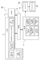
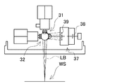
図1に実施の形態1に係るレーザ加工装置100を構成するブロック図を示す。この図に示すレーザ加工装置100は、レーザ制御部1とレーザ出力部2で構成される。レーザ制御部1はレーザ出力部2を制御するコントローラ部を構成し、レーザ出力部2と励起光伝達媒体3で光学的に接続される。またレーザ出力部2はレーザマーキングを行うヘッド部として、レーザ出力光を出力する。このレーザ制御部1は、励起光源を構成するレーザ励起部10を備える。またレーザ制御部1には、必要に応じて加工パターンを入力するための入力部4、各種設定画面を表示させるための表示部5を接続する。一方レーザ出力部2は、固体レーザ媒質に励起光を投入してレーザ共振を発生させるレーザ共振部20と、レーザ出力光を加工対象物(ワーク)Wの表面で走査させるためのレーザ光走査系30とを備える。また必要に応じて、レーザ光走査系30の出力側にfθレンズ等の作業領域集光部40を配置する。
(入力部4、表示部5)
FIG. 1 is a block diagram showing the
(
入力部4はレーザ制御部1に接続され、レーザ加工装置100を操作するための必要な設定を入力してレーザ制御部1に送信する。設定内容はレーザ加工装置100の動作条件や具体的な加工内容等である。入力部4はキーボードやマウス、コンソール等の入力デバイスである。また、入力部4で入力された入力情報を確認したり、レーザ制御部1の状態等を表示するための表示部を別途設けることもできる。表示部5はLCDやブラウン管等のモニタが利用できる。またタッチパネル方式を利用すれば、入力部と表示部を兼用することもできる。これによって、コンピュータ等を外部接続することなく入力部でレーザ加工装置100の必要な設定を行うことができる。
(レーザ制御部1)
The
(Laser controller 1)
レーザ制御部1は、制御部50とメモリ部52とレーザ励起部10と電源回路54とを備える。入力部4から入力された設定内容は、メモリ部52に記録される。制御部50は必要時にメモリ部52から設定内容を読み込み、加工内容に応じた加工信号に基づいてレーザ励起部10を動作させてレーザ出力部2の固体レーザ媒質21を励起する。メモリ部52はRAMやROM等の半導体メモリが利用できる。またメモリ部52はレーザ制御部1に内蔵する他、挿抜可能なPCカードやSDカード(登録商標)等の半導体メモリカード、カード型ハードディスク等のメモリカードを利用することもできる。メモリカードで構成されるメモリ部52は、コンピュータ等の外部機器で容易に書き換え可能であり、コンピュータで設定した内容をメモリカードに書き込み、レーザ制御部1にセットすることで、入力部をレーザ制御部に接続することなく設定を行うことができる。特に半導体メモリはデータの読み込み・書き込みが高速で、しかも機械的動作部分がないため振動等に強く、ハードディスクのようなクラッシュによるデータ消失事故を防止できる。
The
さらに制御部50は、設定された加工を行うよう固体レーザ媒質21で発振されたレーザ光をワークW上で走査させるため、レーザ出力部2のレーザ光走査系30を動作させる走査信号をレーザ光走査系30に出力する。電源回路54は、定電圧電源として、レーザ励起部10へ所定電圧を印加する。加工動作を制御する加工信号は、そのHIGH/LOWに応じてレーザ光のON/OFFが切り替えられ、その1パルスが発振されるレーザ光の1パルスに対応するPWM信号である。PWM信号は、その周波数に応じたデューティ比に基づいてレーザ強度が定められるが、周波数に基づいた走査速度によってもレーザ強度が変化するよう構成することもできる。
(レーザ励起部10)
Further, the
(Laser excitation unit 10)
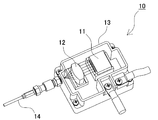
レーザ励起部10は、光学的に接合された励起光源11と励起光集光部12を備える。レーザ励起部10の一例を図2の斜視図に示す。この図に示すレーザ励起部10は、励起光源11と励起光集光部12を励起ケーシング13内に固定している。励起ケーシング13は、熱伝導性に優れた銅等の金属で構成され、励起光源11を効率よく外部に放熱する。励起光源11は半導体レーザ(LD)やランプ等で構成される。図2の例では、複数のLD素子を直線状に並べたLDアレイやLDバーを使用しており、各素子からのレーザ発振がライン状に出力される。レーザ発振は励起光集光部12の入射面に入射されて、出射面から集光されたレーザ励起光として出力される。励起光集光部12はフォーカシングレンズ等で構成される。励起光集光部12からのレーザ励起光は、光ファイバ14等によりレーザ共振部20に入射される。励起光源11と励起光集光部12、光ファイバ14は、空間あるいは光ファイバを介して光学的に結合されている。またレーザ励起部10は、このような部材を予め組み込んだLDユニット或いはLDモジュールが使用できる。ここでは、出力40W〜50Wの高出力なLDユニットを使用し、分岐手段で励起光を分岐させている。またレーザ励起部10から出射される励起光は無偏光とすることができ、これにより偏光状態の変化を考慮する必要が無く設計上有利となる。特に、複数のLD素子を数十個配列したLDアレイから各々得られる光を光ファイバでバンドルして出力するLDユニット自体に出力光を無偏光とする機構を備えることが好ましい。あるいは、レーザ励起部10から光ファイバケーブルで伝送する過程、励起光結合手段等で分岐経路と光学的に結合する過程等において無偏光状態(ランダム偏光)とする構成としてもよい。
The
またレーザ励起部10は、励起光源11を温度調整するための温度調整機構を備える。特にLD素子等の半導体発光素子は、温度によって波長が変化する温度依存性があるため、所望の波長のレーザ励起光を得るよう、LD素子の温度を測定して適切な温度に維持するよう温度調整機構を制御する。温度調整機構は、ペルチェ素子等を利用できる。
(レーザ出力部2)
Further, the
(Laser output unit 2)
このようにしてレーザ励起部10で生成されたレーザ励起光は、励起光伝達媒体3でレーザ出力部2に伝達される。励起光伝達媒体3には光ファイバケーブル等が利用される。またレーザ励起部10の光ファイバ14を、そのまま励起光伝達媒体3として利用してもよい。レーザ出力部2は、レーザ共振部20にレーザ励起光を入射し、レーザ発振させてレーザ出力光を生成すると共に、レーザ光走査系30で作業領域上を所望の加工パターンにてレーザ光を走査させる。
(レーザ共振部20)
The laser excitation light generated in this way by the
(Laser resonator 20)
レーザ共振部20は、レーザ発振によりレーザ光を発生させる固体レーザ共振器又はレーザ発振器ユニットである。このレーザ共振部20は、励起光源11からの励起光を導入する励起光結合手段22と、励起光結合手段22から導入された励起光を第1分岐経路B1と第2分岐経路B2に分岐する分岐手段23と、第1分岐経路B1、第2分岐経路B2から各々の端面に励起光を入射して励起される固体レーザ媒質21と、固体レーザ媒質21が放出する誘導放出光の光路に沿って所定の距離を隔てて対向配置された第1ダイクロイックミラー24、第2ダイクロイックミラー25と、分岐経路と干渉しない位置に配置され、第2ダイクロイックミラー25からの反射光を出力するための出力ミラー26とを備える。ここでは、第1ダイクロイックミラー24をリア側ミラーRM、第2ダイクロイックミラー25を出射側ミラーFMと呼ぶ。リア側ミラーRMはレーザ発振光の進行方向に対して垂直に固定され、一方出射側ミラーFMは、レーザ発振光を出力ミラー26側に反射させるよう、入射方向に対して45°に傾斜されて固定される。
The
一方、出力ミラー26と出射側ミラーFMとの間にはアパーチャ27、Qスイッチ28、レーザシャッタ等が配置される。励起光結合手段22には励起光伝達媒体3である光ファイバケーブルが接続され、レーザ励起部10で発生された励起光がレーザ共振部20に導入されると共に、分岐手段23で分岐されて固体レーザ媒質21の各々の端面に入射される。固体レーザ媒質21が放出する誘導放出光を、出射側ミラーFMとリア側ミラーRMとの間での多重反射により増幅し、Qスイッチ28の動作により短周期にて通断しつつアパーチャ27によりモード選別して、出力ミラー26を経てレーザ光を出力する。このリア側ミラーRMから出射側ミラーFMを介した出力ミラー26まででレーザ共振器が構成される。
On the other hand, an
アパーチャ27は、固体レーザ媒質21の口径よりも小さい開口を誘導放出光の光路の中心に合わせて配された遮蔽板であり、不要なモードの発振を抑えるモード選別作用をなすモードセレクタとして機能する。このモード選別によって、レーザ加工の品質向上を図る。
The
またQスイッチ28は、出力ミラー26と反射ミラーとの間を往復する誘導放出光の光路を短周期にて通断し、共振器としてのメリット数(Q値)を高めて、高速でレーザビームのON/OFFを制御する動作をなす。本実施の形態においては、Qスイッチ周波数は1kHz〜400kHzで可変であり、またCW発振も可能である。
The Q switch 28 cuts off the optical path of the stimulated emission light that travels back and forth between the
出力ミラー26は、出射側ミラーFMからの反射光を出力するハーフミラーであって、分岐経路と干渉しない位置で、レーザ発振光と略直交する方向で第2ダイクロイックミラー25の反射位置に配置される。
The
一方、励起光結合手段22は、励起光伝達媒体3を分岐手段23と光学的に結合するための部材であり、光ファイバケーブルを接続する光ファイバ結合部22aと、光ファイバ結合部22aと分岐手段23との間に配置され、光ファイバ結合部22aを介して入射されたLDユニットからの励起光を平行光に整形するコリメートレンズ22bを備える。コリメートレンズ22bは平凸レンズ等が利用できる。
On the other hand, the pumping light coupling means 22 is a member for optically coupling the pumping
コリメートレンズ22bで平行光とされた励起光は、第1分岐経路B1及び第2分岐経路B2を通じて固体レーザ媒質21の端面側まで伝送された後、リア側ミラーRM、出射側ミラーFMに入射される前に集光レンズで集光される。ここでは、リア側ミラーRMに対向させて第1分岐経路B1上に第1集光レンズ61が、出射側ミラーFMに対向させて第2分岐経路B2上に第2集光レンズ62が、それぞれ配置される。第1集光レンズ61は、後述するようにリア側ミラーRMを透過した励起光の第1励起光R1が固体レーザ媒質21の第1端面に照射される際のスポット径を、固体レーザ媒質21のTEM00モードよりも小さくするように集光する。また第2集光レンズ62は、出射側ミラーFMを透過した励起光の第2励起光R2が固体レーザ媒質21の第2端面に照射される際のスポット径を、固体レーザ媒質21のTEM00モードよりも小さくするように集光する。これら第1集光レンズ61、第2集光レンズ62は平凸レンズ等が利用できる。
(レーザ共振部20の配置)
The excitation light converted into parallel light by the
(Arrangement of laser resonator 20)
分岐手段23は、励起光源11から出力される励起光を、第1励起光R1と第2励起光R2に分岐する。分岐された第1励起光R1、第2励起光R2はそれぞれ、第1分岐経路B1及び第2分岐経路B2に振り分けられ、第1分岐経路B1から固体レーザ媒質21の第1端面に励起光の第1励起光R1を、第2分岐経路B2から第2端面に第2励起光R2を、各々入射させる。このような分岐手段23はハーフミラー等のビームスプリッタBSが利用できる。
The branching
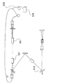
第1分岐経路B1、第2分岐経路B2は、各々ビームスプリッタBS、反射ミラー等の光学系部材で構成される。すなわち、ビームスプリッタBSで分岐された第1励起光R1又は第2励起光R2を、略垂直に反射させる第1反射ミラーM1と、第1反射ミラーM1で反射された反射光又はビームスプリッタBSで分岐された第2励起光R2又は第1励起光R1をさらに略垂直方向に反射させる第2反射ミラーM2と、第2反射ミラーM2で反射された反射光を、略垂直に反射させる第3反射ミラーM3とで分岐経路が形成される。このようにして分岐経路を矩形状に構成することで、固体レーザ媒質21の2方向励起のための分岐経路をコンパクトにでき、さらに各反射ミラーの配置や調整作業を容易にできる。特に、ビームスプリッタBS、第1反射ミラーM1、第2反射ミラーM2、第3反射ミラーM3を同一平面上に配置することにより、各部材の位置決めの調整作業を容易に行えるようになる。この例では、すべての光学部材を1枚の構造基板63に配置させており、シンプルな構成で固体レーザ共振器を設計できる。加えて、励起光源11を1個とすることで、該励起光源11をビームスプリッタBSまで光伝達する媒体を1本にでき、この点においても構成の簡素化に寄与できる。また励起光源11を1個として分岐する構成により、従来の2つのLDで各々の端面から励起する構成に比べ、安価に構成できる利点も得られる。
The first branch path B1 and the second branch path B2 are each composed of an optical system member such as a beam splitter BS and a reflection mirror. That is, the first reflection mirror M1 that reflects the first excitation light R1 or the second excitation light R2 branched by the beam splitter BS substantially vertically and the reflected light reflected by the first reflection mirror M1 or the beam splitter BS. A second reflection mirror M2 that further reflects the branched second excitation light R2 or first excitation light R1 in a substantially vertical direction, and a third reflection that reflects the reflection light reflected by the second reflection mirror M2 substantially vertically. A branch path is formed with the mirror M3. By configuring the branch path in a rectangular shape in this way, the branch path for bi-directional excitation of the solid-
また上記構成は、固体レーザ媒質21や励起光結合手段22等の各部材のレイアウト上の自由度も増すことができる。すなわち、固体レーザ媒質21及びリア側ミラーRM、出射側ミラーFMを矩形状のいずれかの辺上に配置することができ、一方で矩形状のいずれかの頂点で、該頂点をなす矩形状のいずれかの辺の延長線上に、励起光源11からの励起光が入射されるよう配置できる。このように、部材の配置を変更できるので、レーザ共振部20として与えられたスペースや形状に応じた、適切なレイアウトを適宜採用できる利点が得られる。
The above configuration can also increase the degree of freedom in layout of each member such as the solid-
具体的な光学系部材の配置例を、図3に示す。この図に示すレーザ共振部201は、長方形状の分岐経路の一方の長辺側(図3において左側)に固体レーザ媒質21、リア側ミラーRM、出射側ミラーFMを配置し、かつ他方の長辺側(図3において右側)であって、リア側ミラーRMと近い側の頂点にビームスプリッタBS1を配置し、ビームスプリッタBS1と近接させて励起光結合手段22を、励起光が長辺と垂直な方向から入射するように配置している。すなわち図3において、縦方向に長い長方形状の右下の頂点にビームスプリッタBS1を、左下の頂点に第1反射ミラーM11を、右上の頂点に第2反射ミラーM21を、左上の頂点に第3反射ミラーM31を、それぞれ配置している。また第1、第2、第3反射ミラーM11〜M31は、各々入射光を直角に反射させるよう、各頂点を面取りする方向に、すなわち各辺に対して内角135°の方向に傾斜させて固定されている。一方ビームスプリッタBS1は、入射光に対して、直進する透過光と直角に反射させる反射光とに分岐するために、各辺に対して内角45°の方向に傾斜させて固定されている。ビームスプリッタBS1の右側に励起光結合手段22が配置され、光ファイバケーブルと連結された光ファイバ結合部22aを介して入射されたLDユニットからの励起光がコリメートレンズ22bで平行光に整形されて、ビームスプリッタBS1に向かって(図3において左方向に)励起光が入射される。ビームスプリッタBS1は入射光に対して45°の角度で傾斜姿勢に固定されており、直進方向の透過光を第1励起光R1、上方に反射させる反射光を第2励起光R2として、励起光を分岐させる。ビームスプリッタBS1の左側には、入射光に対して45°に傾斜して第1反射ミラーM11が固定されており、第1励起光R1を上方向に反射させる。この反射光は、第1集光レンズ61で集光されてリア側ミラーRMに投入される。以上のようにして、第1分岐経路B1がL字状に形成される。
A specific arrangement example of the optical system members is shown in FIG. The
一方、ビームスプリッタBS1で上方向に反射された第2励起光R2は、入射光に対して45°の傾斜姿勢に固定された第2反射ミラーM21で、水平方向(図3において左方向)に反射される。反射光はビームスプリッタBS1の透過光と平行に進み、入射光に対して45°の傾斜姿勢に固定された第3反射ミラーM31で下方向に反射される。この第2励起光R2の反射光が、第2集光レンズ62で集光されて出射側ミラーFMに投入される。以上のようにして、第2分岐経路B2が逆L字状に形成される。この結果、第1反射ミラーM11で反射された第1励起光R1の反射光と、第3反射ミラーM31で反射された第2励起光R2の反射光とが同一軸線上で対向する。そして第1励起光R1、第2励起光R2が各々リア側ミラーRM、出射側ミラーFMに投入され、これらのダイクロイックミラー間に配置された固体レーザ媒質21によりレーザ発振され、誘導放出光が出射側ミラーFMから取り出される。すなわち、レーザ発振光は45°に傾斜されて固定された出射側ミラーFMで水平方向(図3において左方向)に反射され、Qスイッチ28、アパーチャ27を介して出力ミラー26に到達し、レーザ出力光が出力される。
(実施の形態2)
On the other hand, the second pumping light R2 reflected upward by the beam splitter BS1 is horizontally directed (leftward in FIG. 3) by the second reflecting mirror M21 fixed in an inclined posture of 45 ° with respect to the incident light. Reflected. The reflected light travels parallel to the transmitted light of the beam splitter BS1 and is reflected downward by the third reflecting mirror M31 fixed to the incident light at an inclination of 45 °. The reflected light of the second excitation light R2 is collected by the
(Embodiment 2)
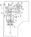
以上のレイアウトは一例であって、ビームスプリッタBSや励起光結合手段22、固体レーザ媒質21の配置は変更することができる。次に、励起光結合手段22の位置を変更したレイアウト例として、実施の形態2に係る固体レーザ発振器の光学系部材の配置例を、図4に示す。この図に示すレーザ共振部202も、長方形状に形成された分岐経路の一方の長辺側(図4において左側)に固体レーザ媒質21、リア側ミラーRM、出射側ミラーFMを配置し、ビームスプリッタBS2を、他方の長辺側(図4において左側)の、リア側ミラーRMと近い側の頂点に配置している。ここでビームスプリッタBS2と近接させて配置する励起光結合手段22を、励起光が長辺上と一致する方向から入射するように配置している。なお、光学部材の配置は、図3と同様、縦方向に長い長方形状の右下の頂点にビームスプリッタBS2、左下の頂点に第1反射ミラーM12、右上の頂点に第2反射ミラーM22、左上の頂点に第3反射ミラーM32を、それぞれ配置している。また第1、第2、第3反射ミラーM12〜M32は、各々入射光を直角に反射させるよう、各頂点を面取りする方向に、すなわち各辺に対して内角135°の方向に傾斜させて固定されている。一方ビームスプリッタBS2は、図3と同様、入射光を直進させる透過光と、直角に反射させる反射光とに分岐するために、長方形状の内角を等分するように45°の角度で固定されている。このビームスプリッタBS2の下側に配置された励起光結合手段22から(図4において上方向に)励起光が入射される。ビームスプリッタBS2は図3と90°異なる傾斜姿勢に固定され、直進方向の透過光を第2励起光R2、水平方向(図4において左向き)に反射させる反射光を第1励起光R1として、励起光を分岐させる。ビームスプリッタBS2の左側には、図3と同様に入射光に対して45°に傾斜して第1反射ミラーM12が固定されており、第1励起光R1を上方向に反射させる。この反射光は、第1集光レンズ61で集光されてリア側ミラーRMに投入される。以上のようにして、第1分岐経路B1がL字状に形成される。
The above layout is an example, and the arrangement of the beam splitter BS, the excitation light coupling means 22, and the solid-
一方、ビームスプリッタBS2で上方向に透過された第2励起光R2は、入射光に対して45°の傾斜姿勢に固定された第2反射ミラーM22で、水平方向(図4において左向き)に反射される。反射光はビームスプリッタBS2の反射光と平行に進み、入射光に対して45°の傾斜姿勢に固定された第3反射ミラーM32で下方向に反射される。この第2励起光R2の反射光が、第2集光レンズ62で集光されて出射側ミラーFMに投入される。以上のようにして、第2分岐経路B2が逆L字状に形成される。以下図3と同様に、第1反射ミラーM12で反射された第1励起光R1の反射光と、第3反射ミラーM32で反射された第2励起光R2の反射光とが同一軸線上で対向し、第1励起光R1、第2励起光R2が各々リア側ミラーRM、出射側ミラーFMに投入されてレーザ発振される。
(実施の形態3)
On the other hand, the second excitation light R2 transmitted upward by the beam splitter BS2 is reflected in the horizontal direction (leftward in FIG. 4) by the second reflection mirror M22 fixed in an inclined posture of 45 ° with respect to the incident light. Is done. The reflected light travels in parallel with the reflected light of the beam splitter BS2, and is reflected downward by the third reflecting mirror M32 fixed at a 45 ° inclination with respect to the incident light. The reflected light of the second excitation light R2 is collected by the
(Embodiment 3)
さらに他のレイアウト例として、実施の形態3に係る固体レーザ発振器の光学系部材の配置例を、図5に示す。この図に示すレーザ共振部203も、長方形状に形成された分岐経路の一方の長辺側(図5において左側)に固体レーザ媒質21、リア側ミラーRM、出射側ミラーFMを配置している。ここではビームスプリッタBS3を、同じ長辺側で、リア側ミラーRMと近い側の頂点に配置している。またビームスプリッタBS3と近接させて配置する励起光結合手段22を、励起光がこの長辺上と一致する方向から入射するように配置している。また光学部材の配置は、縦方向に長い長方形状の左下の頂点にビームスプリッタBS3、右下の頂点に第1反射ミラーM13、右上の頂点に第2反射ミラーM23、左上の頂点に第3反射ミラーM33を、それぞれ配置している。さらに第1、第2、第3反射ミラーM13〜M33は、各々入射光を直角に反射させるよう、各頂点を面取りする方向に、すなわち各辺に対して内角135°の方向に傾斜させた姿勢で固定されている。一方ビームスプリッタBS3は、図3等と同様、入射光を直進させる透過光と、直角に反射させる反射光とに分岐するために、長方形状の内角を等分するように45°の角度で固定されている。図4と同様、ビームスプリッタBS3の下側に配置された励起光結合手段22から(図5において上方向に)励起光が入射され、直進方向の透過光を第1励起光R1、水平方向(図5において右向き)に反射させる反射光を第2励起光R2として、励起光を分岐させる。透過光である第1励起光R1は、第1集光レンズ61で集光されてリア側ミラーRMに投入される。この例では、第1分岐経路B1が直線状に形成される。
As yet another layout example, FIG. 5 shows an arrangement example of the optical system members of the solid-state laser oscillator according to the third embodiment. Also in the
一方、ビームスプリッタBS3で水平方向(図5において右向き)に反射された第2励起光R2は、入射光に対して45°の傾斜姿勢に固定された第1反射ミラーM13で、垂直方向(図5において上向き)に反射される。反射光はビームスプリッタBS3の透過光と平行に進み、入射光に対して45°の傾斜姿勢に固定された第2反射ミラーM23で水平方向(図5において左向き)に反射される。さらに入射光に対して45°の傾斜姿勢に固定された第3反射ミラーM33で、垂直方向(図5において下向き)に反射される。この第2励起光R2の反射光が、第2集光レンズ62で集光されて出射側ミラーFMに投入される。以上のようにして、第2分岐経路B2が逆コ字状に形成される。このようにして、ビームスプリッタBS3で透過された第1励起光R1と、第3反射ミラーM33で反射された第2励起光R2の反射光とが同一軸線上で対向し、第1励起光R1、第2励起光R2が各々リア側ミラーRM、出射側ミラーFMに投入されてレーザ発振される。
(実施の形態4)
On the other hand, the second excitation light R2 reflected in the horizontal direction (rightward in FIG. 5) by the beam splitter BS3 is vertical (see FIG. 5) by the first reflection mirror M13 fixed in an inclined posture of 45 ° with respect to the incident light. (Upward at 5). The reflected light travels parallel to the transmitted light of the beam splitter BS3, and is reflected in the horizontal direction (leftward in FIG. 5) by the second reflecting mirror M23 fixed in an inclined posture of 45 ° with respect to the incident light. Further, the light is reflected in the vertical direction (downward in FIG. 5) by the third reflection mirror M33 fixed in an inclined posture of 45 ° with respect to the incident light. The reflected light of the second excitation light R2 is collected by the
(Embodiment 4)
さらにまた、他のレイアウト例として、実施の形態4に係る固体レーザ発振器の光学系部材の配置例を、図6に示す。この図に示すレーザ共振部204も、長方形状に形成された分岐経路の一方の長辺側(図6において左側)に固体レーザ媒質21、リア側ミラーRM、出射側ミラーFMを配置している。ここではビームスプリッタBS4を、同じ長辺側で、リア側ミラーRMと近い側の頂点に配置している。またビームスプリッタBS4と近接させて配置する励起光結合手段22を、励起光がこの長辺と直交する方向(図6において頂点の左側)から入射するように配置している。また光学部材の配置は、図5と同様に縦方向に長い長方形状の左下の頂点にビームスプリッタBS4、右下の頂点に第1反射ミラーM14、右上の頂点に第2反射ミラーM24、左上の頂点に第3反射ミラーM34を、それぞれ配置している。さらに第1、第2、第3反射ミラーM14〜M34は、各々入射光を直角に反射させるよう、各頂点を面取りする方向に、すなわち各辺に対して内角135°の方向に傾斜させた姿勢で固定されている。一方ビームスプリッタBS4は、図3等と同様、入射光を直進させる透過光と、直角に反射させる反射光とに分岐するために、長方形状の内角を等分するように45°の角度で固定されている。図5と同様、ビームスプリッタBS4の左側に配置された励起光結合手段22から、図6において右向きに励起光が入射され、直進方向の透過光を第2励起光R2、垂直方向(図6において上向き)に反射させる反射光を第2励起光R2として、励起光を分岐させる。反射光である第1励起光R1は、第1集光レンズ61で集光されてリア側ミラーRMに投入される。この例でも第1分岐経路B1は直線状に形成される。
Furthermore, as another layout example, FIG. 6 shows an arrangement example of optical system members of the solid-state laser oscillator according to the fourth embodiment. Also in the
一方、ビームスプリッタBS4を透過して図6において右向きに直進する第2励起光R2は、図5と同様に入射光に対して45°の傾斜姿勢に固定された第1反射ミラーM14で、垂直方向(図6において上向き)に反射される。反射光はビームスプリッタBS4の反射光と平行に進み、入射光に対して45°の傾斜姿勢に固定された第2反射ミラーM24で水平方向(図6において左向き)に反射される。さらに入射光に対して45°の傾斜姿勢に固定された第3反射ミラーM34で、垂直方向(図6において下向き)に反射される。この第2励起光R2の反射光が、第2集光レンズ62で集光されて出射側ミラーFMに投入される。以上のようにして、第2分岐経路B2が逆コ字状に形成される。このようにして、ビームスプリッタBS4で反射された第1励起光R1と、第3反射ミラーM34で反射された第2励起光R2の反射光とが同一軸線上で対向し、第1励起光R1、第2励起光R2が各々リア側ミラーRM、出射側ミラーFMに投入されてレーザ発振される。
(実施の形態5)
On the other hand, the second pumping light R2 that passes through the beam splitter BS4 and goes straight to the right in FIG. 6 is perpendicular to the first reflecting mirror M14 that is fixed at an inclination of 45 ° with respect to the incident light as in FIG. Reflected in the direction (upward in FIG. 6). The reflected light travels parallel to the reflected light of the beam splitter BS4, and is reflected in the horizontal direction (leftward in FIG. 6) by the second reflecting mirror M24 fixed in an inclined posture of 45 ° with respect to the incident light. Further, the light is reflected in the vertical direction (downward in FIG. 6) by the third reflecting mirror M34 fixed in an inclined posture of 45 ° with respect to the incident light. The reflected light of the second excitation light R2 is collected by the
(Embodiment 5)
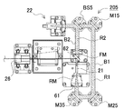
さらにまた、他のレイアウト例として、実施の形態5に係る固体レーザ発振器の光学系部材の配置例を、図7に示す。この図に示すレーザ共振部205も、長方形状に形成された分岐経路の一方の長辺側(図7において左側)に固体レーザ媒質21、リア側ミラーRM、出射側ミラーFMを配置している。ここではビームスプリッタBS5を、同じ長辺側で、出射側ミラーFMと近い側の頂点に配置している。またビームスプリッタBS5と近接させて配置する励起光結合手段22を、励起光がこの長辺と直交する方向(図7において頂点の左側)から入射するように配置している。また光学部材の配置は、縦方向に長い長方形状の左上の頂点にビームスプリッタBS5、右上の頂点に第1反射ミラーM15、右下の頂点に第2反射ミラーM25、左下の頂点に第3反射ミラーM35を、それぞれ配置している。さらに第1、第2、第3反射ミラーM15〜M35は、各々入射光を直角に反射させるよう、各頂点を面取りする方向に、すなわち各辺に対して内角135°の方向に傾斜させた姿勢で固定されている。一方ビームスプリッタBS5は、図3等と同様、入射光を直進させる透過光と、直角に反射させる反射光とに分岐するために、長方形状の内角を等分するように45°の角度で固定されている。ここではビームスプリッタBS5の左側に配置された励起光結合手段22から、図7において右向きに励起光が入射され、直進方向の透過光を第1励起光R1、垂直方向(図7において下向き)に反射させる反射光を第2励起光R2として、励起光を分岐させる。反射光である第2励起光R2は、第2集光レンズ62で集光されて出射側ミラーFMに投入される。この例では第2分岐経路B2が直線状に形成される。
Furthermore, as another layout example, FIG. 7 shows an arrangement example of optical system members of the solid-state laser oscillator according to the fifth embodiment. The
一方、ビームスプリッタBS5を透過して図7において右向きに直進する第1励起光R1は、入射光に対して45°の傾斜姿勢に固定された第1反射ミラーM15で、垂直方向(図7において下向き)に反射される。反射光はビームスプリッタBS5の反射光と平行に進み、入射光に対して45°の傾斜姿勢に固定された第2反射ミラーM25で水平方向(図7において左向き)に反射される。さらに入射光に対して45°の傾斜姿勢に固定された第3反射ミラーM35で、垂直方向(図7において上向き)に反射される。この第1励起光R1の反射光が、第1集光レンズ61で集光されてリア側ミラーRMに投入される。以上のようにして、第1分岐経路B1がコ字状に形成される。このようにして、ビームスプリッタBS5で反射された第2励起光R2と、第3反射ミラーM35で反射された第1励起光R1の反射光とが同一軸線上で対向し、第1励起光R1、第2励起光R2が各々リア側ミラーRM、出射側ミラーFMに投入されてレーザ発振される。
(実施の形態6)
On the other hand, the first pumping light R1 that passes through the beam splitter BS5 and goes straight to the right in FIG. 7 is a first reflecting mirror M15 that is fixed in an inclined posture of 45 ° with respect to the incident light, and is in the vertical direction (in FIG. 7). Reflected downward). The reflected light travels in parallel with the reflected light of the beam splitter BS5, and is reflected in the horizontal direction (leftward in FIG. 7) by the second reflecting mirror M25 fixed in an inclined posture of 45 ° with respect to the incident light. Further, the light is reflected in the vertical direction (upward in FIG. 7) by the third reflecting mirror M35 fixed at a 45 ° inclination with respect to the incident light. The reflected light of the first excitation light R1 is collected by the
(Embodiment 6)
さらにまた、他のレイアウト例として、実施の形態6に係る固体レーザ発振器の光学系部材の配置例を、図8に示す。この図に示すレーザ共振部206も、長方形状に形成された分岐経路の一方の長辺側(図8において左側)に固体レーザ媒質21、リア側ミラーRM、出射側ミラーFMを配置している。ここではビームスプリッタBS6を、同じ長辺側で、出射側ミラーFMと近い側の頂点に配置している。またビームスプリッタBS6と近接させて配置する励起光結合手段22を、励起光がこの長辺と一致する方向(図8において頂点の上側)から入射するように配置している。また光学部材の配置は、図7と同様に縦方向に長い長方形状の左上の頂点にビームスプリッタBS6、右上の頂点に第1反射ミラーM16、右下の頂点に第2反射ミラーM26、左下の頂点に第3反射ミラーM36を、それぞれ配置している。さらに第1、第2、第3反射ミラーM16〜M36は、各々入射光を直角に反射させるよう、各頂点を面取りする方向に、すなわち各辺に対して内角135°の方向に傾斜させた姿勢で固定されている。一方ビームスプリッタBS6は、図3等と同様、入射光を直進させる透過光と、直角に反射させる反射光とに分岐するために、長方形状の内角を等分するように45°の角度で固定されている。ここではビームスプリッタBS6の上側に配置された励起光結合手段22から、図8において下向きに励起光が入射され、直進方向の透過光を第2励起光R2、水平方向(図8において右向き)に反射させる反射光を第1励起光R1として、励起光を分岐させる。透過光である第2励起光R2は、第2集光レンズ62で集光されて出射側ミラーFMに投入される。この例でも第2分岐経路B2が直線状に形成される。
Furthermore, as another layout example, FIG. 8 shows an arrangement example of the optical system members of the solid-state laser oscillator according to the sixth embodiment. Also in the
一方、ビームスプリッタBS6で反射されて図8において右向きに直進する第1励起光R1は、図7と同様に入射光に対して45°の傾斜姿勢に固定された第1反射ミラーM16で、垂直方向(図8において下向き)に反射される。反射光はビームスプリッタBS6の透過光と平行に進み、入射光に対して45°の傾斜姿勢に固定された第2反射ミラーM26で水平方向(図8において左向き)に反射される。さらに入射光に対して45°の傾斜姿勢に固定された第3反射ミラーM36で、垂直方向(図8において上向き)に反射される。この第1励起光R1の反射光が、第1集光レンズ61で集光されてリア側ミラーRMに投入される。以上のようにして、第1分岐経路B1がコ字状に形成される。このようにして、ビームスプリッタBS6で透過された第2励起光R2と、第3反射ミラーM36で反射された第1励起光R1の反射光とが同一軸線上で対向し、第1励起光R1、第2励起光R2が各々リア側ミラーRM、出射側ミラーFMに投入されてレーザ発振される。
(実施の形態7)
On the other hand, the first pumping light R1 reflected by the beam splitter BS6 and traveling straight to the right in FIG. 8 is perpendicular to the first reflecting mirror M16 fixed at a 45 ° inclination with respect to the incident light as in FIG. Reflected in the direction (downward in FIG. 8). The reflected light travels parallel to the transmitted light of the beam splitter BS6, and is reflected in the horizontal direction (leftward in FIG. 8) by the second reflecting mirror M26 fixed at a 45 ° inclination with respect to the incident light. Further, the light is reflected in the vertical direction (upward in FIG. 8) by the third reflecting mirror M36 fixed at an inclination of 45 ° with respect to the incident light. The reflected light of the first excitation light R1 is collected by the
(Embodiment 7)
さらにまた、他のレイアウト例として、実施の形態7に係る固体レーザ発振器の光学系部材の配置例を、図9に示す。この図に示すレーザ共振部207も、長方形状に形成された分岐経路の一方の長辺側(図9において左側)に固体レーザ媒質21、リア側ミラーRM、出射側ミラーFMを配置している。ここではビームスプリッタBS7を、他方の長辺側(図9において右側)の、出射側ミラーFMと近い側の頂点に配置している。またビームスプリッタBS7と近接させて配置する励起光結合手段22を、励起光がこの長辺と一致する方向(図9において頂点の上側)から入射するように配置している。また光学部材の配置は、縦方向に長い長方形状の右上の頂点にビームスプリッタBS7、右下の頂点に第1反射ミラーM17、左下の頂点に第2反射ミラーM27、左上の頂点に第3反射ミラーM37を、それぞれ配置している。さらに第1、第2、第3反射ミラーM17〜M37は、各々入射光を直角に反射させるよう、各頂点を面取りする方向に、すなわち各辺に対して内角135°の方向に傾斜させた姿勢で固定されている。一方ビームスプリッタBS7は、図3等と同様、入射光を直進させる透過光と、直角に反射させる反射光とに分岐するために、長方形状の内角を等分するように45°の角度で固定されている。ここではビームスプリッタBS7の上側に配置された励起光結合手段22から、図9において下向きに励起光が入射され、直進方向の透過光を第1励起光R1、水平方向(図9において左向き)に反射させる反射光を第2励起光R2として、励起光を分岐させる。ビームスプリッタBS7の左側には、入射光に対して45°に傾斜して第3反射ミラーM37が固定されており、第2励起光R2を下方向に反射させる。この反射光は、第2集光レンズ62で集光されて出射側ミラーFMに投入される。以上のようにして、第2分岐経路B2が逆L字状に形成される。
Furthermore, as another layout example, FIG. 9 shows an arrangement example of optical system members of the solid-state laser oscillator according to the seventh embodiment. Also in the
一方、ビームスプリッタBS7で透過されて図9において下向きに直進する第1励起光R1は、入射光に対して45°の傾斜姿勢に固定された第1反射ミラーM17で、水平方向(図9において左向き)に反射される。反射光はビームスプリッタBS7の反射光と平行に進み、入射光に対して45°の傾斜姿勢に固定された第2反射ミラーM27で垂直方向(図9において上向き)に反射される。この第1励起光R1の反射光が、第1集光レンズ61で集光されてリア側ミラーRMに投入される。以上のようにして、第1分岐経路B1がU字状に形成される。このようにして、第3反射ミラーM37で反射された第2励起光R2と、第2反射ミラーM27で反射された第1励起光R1の反射光とが同一軸線上で対向し、第1励起光R1、第2励起光R2が各々リア側ミラーRM、出射側ミラーFMに投入されてレーザ発振される。
(実施の形態8)
On the other hand, the first excitation light R1 transmitted through the beam splitter BS7 and traveling straight downward in FIG. 9 is a horizontal direction (in FIG. 9) by the first reflection mirror M17 fixed at a 45 ° inclination with respect to the incident light. Reflected left). The reflected light travels parallel to the reflected light of the beam splitter BS7, and is reflected in the vertical direction (upward in FIG. 9) by the second reflecting mirror M27 fixed in an inclined posture of 45 ° with respect to the incident light. The reflected light of the first excitation light R1 is collected by the
(Embodiment 8)
さらにまた、他のレイアウト例として、実施の形態8に係る固体レーザ発振器の光学系部材の配置例を、図10に示す。この図に示すレーザ共振部208も、長方形状に形成された分岐経路の一方の長辺側(図10において左側)に固体レーザ媒質21、リア側ミラーRM、出射側ミラーFMを配置している。ここではビームスプリッタBS8を、他方の長辺側(図10において右側)の、出射側ミラーFMと近い側の頂点に配置している。またビームスプリッタBS8と近接させて配置する励起光結合手段22を、励起光がこの長辺と直交する方向(図10において頂点の右側)から入射するように配置している。また光学部材の配置は、図9と同様に縦方向に長い長方形状の右上の頂点にビームスプリッタBS8、右下の頂点に第1反射ミラーM18、左下の頂点に第2反射ミラーM28、左上の頂点に第3反射ミラーM38を、それぞれ配置している。さらに第1、第2、第3反射ミラーM18〜M38は、各々入射光を直角に反射させるよう、各頂点を面取りする方向に、すなわち各辺に対して内角135°の方向に傾斜させた姿勢で固定されている。一方ビームスプリッタBS8は、図3等と同様、入射光を直進させる透過光と、直角に反射させる反射光とに分岐するために、長方形状の内角を等分するように45°の角度で固定されている。ここではビームスプリッタBS8の右側に配置された励起光結合手段22から、図10において左向きに励起光が入射され、直進方向の透過光を第2励起光R2、垂直方向(図10において下向き)に反射させる反射光を第1励起光R1として、励起光を分岐させる。ビームスプリッタBS8の左側には、入射光に対して45°に傾斜して第3反射ミラーM38が固定されており、透過した第2励起光R2を下方向に反射させる。この反射光は、第2集光レンズ62で集光されて出射側ミラーFMに投入される。以上のようにして、第2分岐経路B2が逆L字状に形成される。
Furthermore, as another layout example, FIG. 10 shows an arrangement example of the optical system members of the solid-state laser oscillator according to the eighth embodiment. Also in the
一方、ビームスプリッタBS8で反射されて図10において下向きに進行する第1励起光R1は、入射光に対して45°の傾斜姿勢に固定された第1反射ミラーM18で、水平方向(図10において左向き)に反射される。反射光はビームスプリッタBS8の透過光と平行に進み、入射光に対して45°の傾斜姿勢に固定された第2反射ミラーM28で垂直方向(図10において上向き)に反射される。この第1励起光R1の反射光が、第1集光レンズ61で集光されてリア側ミラーRMに投入される。以上のようにして、第1分岐経路B1がU字状に形成される。このようにして、第3反射ミラーM38で反射された第2励起光R2と、第2反射ミラーM28で反射された第1励起光R1の反射光とが同一軸線上で対向し、第1励起光R1、第2励起光R2が各々リア側ミラーRM、出射側ミラーFMに投入されてレーザ発振される。
On the other hand, the first excitation light R1 that is reflected by the beam splitter BS8 and travels downward in FIG. 10 is a first reflection mirror M18 that is fixed in an inclined posture of 45 ° with respect to the incident light, and in the horizontal direction (in FIG. Reflected left). The reflected light travels in parallel with the transmitted light of the beam splitter BS8, and is reflected in the vertical direction (upward in FIG. 10) by the second reflecting mirror M28 fixed in an inclined posture of 45 ° with respect to the incident light. The reflected light of the first excitation light R1 is collected by the
以上のように、励起光の分岐経路を長方形状に構成することで、固体レーザ媒質21とこれに励起光を投入する励起光源11の配置を簡素化できる。このような配置パターンの変形例を纏めて図11の模式図に示す。この図において、括弧内の数字は実施の形態の番号に対応させている。このように、第1分岐経路と第2分岐経路とを合わせた分岐経路Bを長方形状に構成し、長方形状の一辺(ここでは長辺)の軸上に固体レーザ媒質21を配置し、さらに長方形状のいずれかの隅部で、いずれかの辺に沿って励起光を入射するよう配置することができる。このため、分岐経路Bを長方形状に維持したまま励起光源11の配置位置を容易に変更できる。このように、レイアウトの設計変更を容易に行うことができ、極めて簡素で且つコンパクトな構成で2方向励起を実現できる。
As described above, the arrangement of the
固体レーザ媒質21は、図11に示すように長方形状のいずれかの長辺上に配置することが望ましい。固体レーザ媒質21を配置する辺は、固体レーザ媒質21に加えてリア側ミラーRM、出射側ミラーFM等を配置するため、ある程度の長さが必要な一方、短辺上にはこれらを配置する必要がないため、この部分を短くして分岐経路の長方形状をコンパクトにでき、レーザ共振器の小型化を実現できるからである。ただ、レーザ共振器のレイアウトによっては、図12に示すように短辺側に配置することもできる。また分岐経路は長方形状に限られず、図13に示すように正方形状に構成しても良い。これにより、固体レーザ媒質21をいずれの辺にも配置できるので、レイアウトの自由度が一層高められる。すなわち、各光学部材の配置を物理的なスペースやレイアウトの要求に応じて適切に配分し、効率的な配置を採用できる。
As shown in FIG. 11, it is desirable that the solid-
なお後述するように、固体レーザ媒質21のリア面側に励起光の分岐成分を多く投入する観点からは、反射ミラーによる反射回数が少なく損失の少ない実施形態3や実施形態4、あるいは実施形態1、2が好ましいと言える。特に実施形態3では、リア面側に投入する第1分岐成分を反射させることなく第1端面に投入できるので、損失低減の観点からは好ましい。ただ、ビームスプリッタによる分岐の比率の調整によって、他の実施形態でも同様の効果を得られることはいうまでもない。ビームスプリッタ側の調整によって、反射ミラーによる損失等を考慮して設計でき、レイアウトの制約を受けることなく自由な配置が可能となる。
(固体レーザ媒質21)
As will be described later, from the viewpoint of adding a lot of excitation light branching components to the rear surface side of the solid-
(Solid laser medium 21)
固体レーザ媒質21は、一方向に延長され、長手方向に2つの端面を有する結晶である。ここで端面は、励起光の入射面を構成する第1端面と、第1端面の反対側であって、励起光の入射面及び励起光の取り出し面を構成する第2端面とで構成される。図3の例では第2端面を取り出し面(出射面)といい、第1端面をリア面(入射面)という。また出射面は出射側ミラーFMと、リア面はリア側ミラーRMと、それぞれ対向させている。さらにビームスプリッタBSで第1励起光R1、第2励起光R2に分岐された励起光の内、第1励起光R1がリア面側に、第2励起光R2が出射面側に、それぞれ入射される。
The solid-
上記の例では、固体レーザ媒質21としてロッド状のNd:YVO4結晶を用いた。また固体レーザ媒質21の励起用半導体レーザの波長は、このNd:YVO4の吸収スペクトルの中心波長である808nm近傍に設定した。ただ、この例に限られず他の固体レーザ媒質21として、例えば希土類をドープしたYAG、LiSrF、LiCaF、YLF、NAB、KNP、LNP、NYAB、NPP、GGG等も用いることもできる。また、固体レーザ媒質21に波長変換素子を組み合わせて、出力されるレーザ光の波長を任意の波長に変換できる。波長変換素子としては、例えばKTP(KTiPO4)、有機非線形光学材料や他の無機非線形光学材料、例えばKN(KNbO3)、KAP(KAsPO4)、BBO、LBOや、バルク型の分極反転素子(LiNbO3(Periodically Polled Lithium Niobate :PPLN)、LiTaO3等)が利用できる。また、Ho、Er、Tm、Sm、Nd等の希土類をドープしたフッ化物ファイバを用いたアップコンバージョンによるレーザの励起光源用半導体レーザを用いることもできる。このように、本実施の形態においてはレーザ発生源として様々なタイプを適宜利用できる。
(Nd濃度)
In the above example, a rod-shaped Nd: YVO 4 crystal is used as the solid-
(Nd concentration)
ロッド状の固体レーザ媒質21結晶は、円柱状、角柱状いずれの形状でも利用できる。ここでは角柱状の固体レーザ媒質21結晶として、端面が3mm(H)×3mm(W)で長さ(L)が15mmの直方体状としたNd:YVO4結晶を使用した。さらにNdの濃度は、1%以下とすることが好ましい。
The rod-shaped
一般に、Ndの濃度を高くするほど、レーザ光の吸収が良くなる。反面、濃度を高くしすぎると励起光が結晶の深部まで浸透せず、表面の狭い領域で励起されてしまう傾向がある。特にNd:YVO4結晶は熱伝導係数が小さいので、LDユニットが高出力になると、熱レンズを生じさせ破損する虞がある。またYVO4結晶は一軸性結晶で強いへき開を持つため、C軸に沿って割れやすい性質がある。このように、高濃度の結晶を用いることで強熱レンズが発生し易くなり、共振器の動作が不安定となってビーム品質の低下を招くと共に、急激な励起光の投入は結晶の割れを引き起こす虞もあった。特にYVO4結晶は一軸性結晶で強いへき開性を持つため、C軸に沿って割れやすいという性質を持つ。これを緩和するためにはNd濃度を低くすることが有効である。 In general, the higher the Nd concentration, the better the absorption of laser light. On the other hand, if the concentration is too high, the excitation light does not penetrate to the deep part of the crystal and tends to be excited in a narrow surface area. In particular, since the Nd: YVO 4 crystal has a small thermal conductivity coefficient, if the LD unit has a high output, a thermal lens may be generated and damaged. YVO 4 crystal is a uniaxial crystal and has a strong cleavage, so that it has a property of being easily broken along the C axis. As described above, the use of a high concentration crystal makes it easy to generate an overheated lens, which causes the operation of the resonator to become unstable, leading to a decrease in beam quality. There was also a risk of causing it. In particular, the YVO 4 crystal is a uniaxial crystal and has a strong cleavage property, and therefore has a property of being easily broken along the C axis. In order to alleviate this, it is effective to lower the Nd concentration.
ただ、Nd濃度を低くすると結晶へのトータルの吸収量は増加するものの、レーザビームモードと吸収部との空間マッチングが低下するために、励起光を有効に利用できない状態となって吸収効率が低下する。加えて、低濃度の結晶を用いた場合には、励起光源11であるLDの波長に対して敏感になり、安定した波長が得られないという問題もあった。したがって、これらを勘案した上でNdの濃度を適切に調整する必要がある。
However, if the Nd concentration is lowered, the total amount of absorption into the crystal increases, but the spatial matching between the laser beam mode and the absorption section decreases, so that the excitation light cannot be used effectively and the absorption efficiency decreases. To do. In addition, when a low concentration crystal is used, there is a problem that it becomes sensitive to the wavelength of the LD that is the
図14に、Nd:YVO4結晶において、励起光の波長に対する吸収効率の変化を示すグラフを示す。ここでは、Nd:YVO4結晶として端面が3mm×3mmの直方体状とし、結晶長とNd濃度を変化させた複数の結晶で、総励起光に対する吸収光の比率を比較した。具体的には、結晶長が15mmの場合のNd濃度を0.10%、0.20%、0.27%、0.30%、0.40%と変化させ、またNd濃度0.27%の場合で結晶長を10mmに変化させた例につき、それぞれ測定した。この図に示すように、概ねNd濃度を高くするほどレーザ光の吸収効率も高くなる。またいずれも励起光の波長が808nm〜809nm近傍で吸収効率のピークを示した。ただし、Nd濃度を上げすぎると熱による不安定化や破損を生じる。このため固体レーザ媒質21のNd濃度は1%以下とし、好ましくは0.1%〜0.4%の範囲とする。ただ、実際に製造される固体レーザ媒質21結晶のNd濃度には、±0.03%〜0.05%程度のばらつきがあるため、これらを考慮して0.22%〜0.32%程度に設定される。最も好ましくは0.27%付近とすることで、バランスよく吸収効率を維持できる。また結晶長(L)を短くすると吸収効率が低下する傾向が見られたことから、10mm〜20mm程度に設定し、好適には13mm〜17mm、より好ましくは15mm近傍の結晶を用いる。
FIG. 14 is a graph showing a change in absorption efficiency with respect to the wavelength of excitation light in an Nd: YVO 4 crystal. Here, the ratio of the absorbed light to the total excitation light was compared for a plurality of crystals having Nd: YVO 4 crystals with end faces of 3 mm × 3 mm and varying the crystal length and Nd concentration. Specifically, the Nd concentration when the crystal length is 15 mm is changed to 0.10%, 0.20%, 0.27%, 0.30%, 0.40%, and the Nd concentration is 0.27%. In this case, the measurement was performed for each of the examples in which the crystal length was changed to 10 mm. As shown in this figure, the higher the Nd concentration, the higher the laser beam absorption efficiency. In both cases, the absorption efficiency peaked when the wavelength of the excitation light was around 808 nm to 809 nm. However, if the Nd concentration is increased too much, instability or damage due to heat occurs. For this reason, the Nd concentration of the solid-
なお、固体レーザ媒質21結晶の断面は、励起光のスポット径よりも大きければ足り、また結晶形状も直方体状に限られず、円柱状その他の形状が適宜利用できる。例えば励起光のスポット径がφ1mmであれば、この大きさの円柱状としてもよい。ただ、固体レーザ媒質21結晶が細いと破損し易くなる等の問題があり、組み立て時における結晶の取り扱いの容易さを考慮して、結晶端面の面積や結晶の形状は、一定の大きさとすることが有利であるため、ここでは結晶端面を3mm×3mmの直方体状とした。
Note that the cross section of the crystal of the solid-
また必要に応じてNd:YVO4結晶の側面に金メッキ等を施すことで熱レンズ効果を抑制し、固体レーザ媒質21の発振モードを強化することもできる。
(2方向励起方式)
If necessary, the thermal lens effect can be suppressed by applying gold plating or the like to the side surface of the Nd: YVO 4 crystal, and the oscillation mode of the solid-
(Bidirectional excitation method)
固体レーザ媒質21を励起するレーザ加工装置では、量子効率の限界から、励起パワーのうち3割〜4割が熱となり失われてしまう。そのため極限的な性能を発揮させるためには、強励起により顕在化する熱複屈折や熱レンズ、熱複レンズ、更には熱による破壊等の様々な熱問題を解決する必要がある。特にLD励起固体レーザ加工装置においては、固体レーザ媒質21の励起光吸収に伴う発熱が結晶そのものにレンズ効果を誘起し、熱レンズを生じさせる。熱レンズはレーザ共振器の安定性を著しく阻害し、共振器の設計の大きな障害となる。このような問題に対し、本実施の形態では2方向励起方式を採用し、かつレーザ励起部10として一の励起光源11を使用し、これを分岐して各端面から投入する構成とすることで、熱レンズ等の発生を抑制することに成功した。またこれに加えて、励起波長に対する安定性や立ち上がり特性の改善の効果も得られる。
(波長変化に対する安定性)
In the laser processing apparatus that excites the solid-
(Stability against wavelength change)
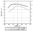
図15に、LDユニットの波長に対するレーザ出力光の変化を、1方向励起と2方向励起で比較したグラフを示す。ここでも、Nd:YVO4結晶として端面が3mm×3mmの直方体状を使用し、1方向励起としてNd濃度が0.27%で結晶長が10mm、2方向励起としてNd濃度が0.27%で結晶長が15mmのものを使用した。この図から示すように、1方向励起では、808nmを中心として励起光の波長がずれるとレーザ出力光も大きく変化する。このため、LDユニットのピーク波長のばらつきによりレーザ出力が変化してしまい、均質なレーザ加工装置を得ることが困難となる。特に半導体発光素子は一般に個体差があり、波長ばらつきが生じやすい傾向にあるため、通常は±2nm〜3nm程度の誤差を考慮する必要がある。さらに励起光の波長は温度依存性もあるため、ペルチェ素子などを使用したLD素子の温度制御も必要となる。このようなことから、従来は波長ばらつきを考慮した上で、最もレーザ出力が低くなるものに合わせて設計することが行われており、本来の出力が生かされていなかった。 FIG. 15 shows a graph comparing the change in laser output light with respect to the wavelength of the LD unit by unidirectional excitation and bidirectional excitation. Here, a rectangular parallelepiped shape having an end face of 3 mm × 3 mm is used as the Nd: YVO 4 crystal, the Nd concentration is 0.27% as the unidirectional excitation, the crystal length is 10 mm, and the Nd concentration is 0.27% as the bidirectional excitation. A crystal length of 15 mm was used. As shown in this figure, in the unidirectional excitation, when the wavelength of the excitation light is shifted around 808 nm, the laser output light also changes greatly. For this reason, the laser output changes due to variations in the peak wavelength of the LD unit, making it difficult to obtain a homogeneous laser processing apparatus. In particular, semiconductor light-emitting elements generally have individual differences and tend to cause wavelength variations, so it is usually necessary to consider an error of about ± 2 nm to 3 nm. Furthermore, since the wavelength of the excitation light has temperature dependence, it is necessary to control the temperature of the LD element using a Peltier element or the like. For this reason, in the past, design was made in accordance with the lowest laser output in consideration of wavelength variation, and the original output was not utilized.
これに対し、2方向励起では、励起光が808nmからずれても、レーザ出力光が安定している。このことから、2方向励起により励起光の波長依存性を抑制し、LDユニットの波長変化によらず安定したレーザ出力光を得ることができることが確認できた。
(立ち上がり特性)
On the other hand, in the two-way excitation, the laser output light is stable even if the excitation light deviates from 808 nm. From this, it was confirmed that the wavelength dependence of the excitation light was suppressed by two-way excitation, and a stable laser output light could be obtained regardless of the wavelength change of the LD unit.
(Rise characteristics)
さらに図16に、レーザ出力光の時間変化を1方向励起と2方向励起で比較したグラフを示す。この図においても、Nd濃度が0.27%で端面3mm×3mmの直方体状Nd:YVO4結晶を使用し、LDユニットの波長を806nm、808nm、810nmに変化させ、1方向励起及び2方向励起それぞれのLDユニットの電流を0Aから35Aに変化させたときのレーザ出力光の時間変化を測定した。なお、結晶長は比較試験の都合上、10mm(一方向励起)、15mm(2方向励起)とした。この図から示すように、1方向励起では、励起波長が808nm、810nmのものではなだらかな上昇を示し、また806nmでは逆にオーバーシュートが発生しており、さらに出力の安定までに約1.4秒要している。一方、2方向励起では、いずれの波長においても急峻な立ち上がりと早期の安定性を示しており、レーザの立ち上がり特性が優れていることが確認された。また806nmでのオーバーシュートも、極低レベルに抑制されている。 Further, FIG. 16 shows a graph comparing the temporal change of the laser output light between the one-directional excitation and the two-directional excitation. Also in this figure, a rectangular parallelepiped Nd: YVO 4 crystal having an Nd concentration of 0.27% and an end face of 3 mm × 3 mm is used, and the wavelength of the LD unit is changed to 806 nm, 808 nm, and 810 nm, and one-directional excitation and two-directional excitation are performed. The time change of the laser output light when the current of each LD unit was changed from 0 A to 35 A was measured. The crystal length was set to 10 mm (unidirectional excitation) and 15 mm (bidirectional excitation) for convenience of the comparative test. As shown in this figure, in the unidirectional excitation, when the excitation wavelength is 808 nm or 810 nm, a moderate increase is observed. On the other hand, overshoot occurs at 806 nm, and about 1.4 until the output is stabilized. It takes seconds. On the other hand, in the bi-directional excitation, a steep rise and early stability were exhibited at any wavelength, and it was confirmed that the laser rise characteristics were excellent. Moreover, the overshoot at 806 nm is also suppressed to an extremely low level.
さらにこのことを確認すべく、図17に、図16と同じくNd濃度0.27%、3mmx3mmx15mmの直方体状Nd:YVO4結晶を使用した2方向励起における、LDユニットの電流を0Aから45Aに変化させた際のレーザ出力光の時間変化を、ホトダイオードで測定した波形を示す。この図からも明らかなように、約20ms程度の極めて短時間で所望のレーザ出力光のレベルに到達し、オーバーシュートを生じることなく安定した出力が得られていることが確認できた。このように、本実施の形態の条件に従えば、レーザ出力光の立ち上がり時に出力が安定するまでに要する時間を従来の1/10以下に高速化できる。またこの結果、加工精度を維持しつつ応答性、追従性を高め、待機時間を縮小した高速な加工も実現できる。従来のレーザ加工においては、レーザ出力の応答性の問題から、レーザ加工パターンのブロック毎にレーザ出力を変化させることができず、レーザ出力を変化させる際は出力が安定するまでの間待機する待機時間(例えば300ms)が必要であった。これに対し、上記構成では立ち上がり時の安定性に優れるため、高速な追従が可能で、従来困難であった、レーザ加工パターンのブロック毎にレーザ出力を変化させることも可能となる。 To confirm this, FIG. 17 shows that the LD unit current is changed from 0 A to 45 A in the bi-directional excitation using a rectangular Nd: YVO 4 crystal having a Nd concentration of 0.27% and 3 mm × 3 mm × 15 mm as in FIG. The waveform which measured the time change of the laser output light at the time of making it with the photodiode is shown. As is apparent from this figure, it was confirmed that the desired laser output light level was reached in an extremely short time of about 20 ms and a stable output was obtained without causing overshoot. As described above, according to the conditions of the present embodiment, the time required for the output to stabilize at the rise of the laser output light can be increased to 1/10 or less of the conventional time. As a result, it is possible to realize high-speed machining with improved responsiveness and follow-up while maintaining machining accuracy and reduced standby time. In conventional laser processing, due to the problem of responsiveness of laser output, the laser output cannot be changed for each block of the laser processing pattern, and when changing the laser output, it waits until the output stabilizes. Time (eg 300 ms) was required. On the other hand, since the above configuration is excellent in stability at the time of start-up, high-speed tracking is possible, and the laser output can be changed for each block of the laser processing pattern, which has been difficult in the past.
このように、上記構成を採用することでLDユニットの波長に対してレーザ出力の変化を抑制し、さらにレーザ出力値の変化に対して、出力されるレーザ光の追従性が速いという優れた利点を実現している。本発明者の行った試験によれば、従来例ではレーザ出力光の設定を0%から100%に変化させた際の、実際に出力されるレーザ出力光の追従性は300msecであったのに対し、本実施の形態では20msecを達成した。
(分岐手段23による分岐比率の調整)
In this way, by adopting the above configuration, it is possible to suppress the change in the laser output with respect to the wavelength of the LD unit, and further, the excellent advantage that the followability of the output laser light is fast with respect to the change in the laser output value. Is realized. According to the test conducted by the present inventor, in the conventional example, when the setting of the laser output light is changed from 0% to 100%, the followability of the actually output laser output light is 300 msec. On the other hand, 20 msec was achieved in this embodiment.
(Adjustment of branching ratio by branching means 23)
単一の励起光源11から2方向に分岐されたレーザ励起光は、固体レーザ媒質21の長手方向の各端面から各々ポンピングされる。この際、リア側ミラーRM側から入力する励起光の大きさを、出射側ミラーFM側から入力する励起光より大きくしている。本発明者は熱レンズについて鋭意研究した結果、固体レーザ媒質の出射側よりもリア側で発生した熱レンズの方が、共振器内部に与える影響が小さいとの知見を得た。図3の構成においては、ビームスプリッタBSの反射率によって、リア側ミラーRMと出射側ミラーFMへの分岐比率を調整している。すなわち、反射率が高いほど出射面側により多くの励起光が照射され、逆に反射率が低いほど、即ち透過率が高いほどリア面側に多くの励起光が照射される。ここでは、ビームスプリッタBSでの分岐比率は、リア面側の結晶端面に対して総パワーの50%以上が投入される構成とすることが好ましい。
The laser excitation light branched in two directions from the single
また、反射率の更なる最適化を図るため、2方向励起方式においてビームスプリッタの反射率を変更して、励起光源のLDのパワーに対するレーザ出力光のパワーを測定した結果を、図18及び図19に示す。これらの図においては、ビームスプリッタの反射率を20%、33%、45%とした場合の典型的な出力特性を測定し、図18はCW動作時、図19はQスイッチ動作時の出力をそれぞれ示している。これらの図から明らかなように、励起光源のLDパワーが高くなるにつれてレーザ出力も上昇するが、CW動作時で45W付近、Qスイッチ動作時で40W付近より、熱レンズの特長である出力の飽和、低下が見られる。この状態では、ビームモードも悪化していることが観察された。このことから、反射率が低すぎてもレーザ出力の低下が顕著となることが確認された。実用レベルにおいては、反射率を30%〜50%の範囲とすることが好ましい。また、最も好ましくは反射率が33%付近、すなわちビームスプリッタが入射光をリア面と出射面に分岐させる比率を、ほぼ2:1に設定する。この値近傍で、最も高いレーザ出力を得ており、レーザ出力の低下を最小限に抑えた高効率な動作が得られることが確認できた。上記数値範囲の優位性は、CW動作時、Qスイッチ動作時のいずれにおいても確認された。なお、Qスイッチ動作の方が、CW動作時に比べて全体としてレーザ出力が低下しており、また励起光が低い段階から低下が生じていることから、熱レンズの影響を受け易いことが確認された。 Further, in order to further optimize the reflectivity, the reflectivity of the beam splitter is changed in the two-way excitation method, and the result of measuring the power of the laser output light with respect to the power of the LD of the excitation light source is shown in FIGS. 19 shows. In these figures, typical output characteristics when the reflectivity of the beam splitter is 20%, 33%, and 45% are measured. FIG. 18 shows the output during CW operation, and FIG. 19 shows the output during Q switch operation. Each is shown. As is clear from these figures, the laser output increases as the LD power of the excitation light source increases, but the saturation of the output, which is a feature of the thermal lens, from around 45 W during CW operation and from around 40 W during Q switch operation. A decrease is seen. In this state, it was observed that the beam mode was also deteriorated. From this, it was confirmed that the decrease in the laser output becomes remarkable even when the reflectance is too low. In practical use, the reflectance is preferably in the range of 30% to 50%. Most preferably, the reflectance is set to around 33%, that is, the ratio at which the beam splitter splits the incident light into the rear surface and the output surface is set to approximately 2: 1. In the vicinity of this value, the highest laser output was obtained, and it was confirmed that high-efficiency operation with minimal reduction in laser output was obtained. The superiority of the above numerical range was confirmed both in CW operation and in Q switch operation. In addition, it is confirmed that the Q switch operation is more susceptible to the influence of the thermal lens because the laser output as a whole is lower than in the CW operation, and the excitation light is reduced from a low stage. It was.
なお、リア側に分岐させる比率を上げすぎると、励起光がリア側に偏在してこの面で熱レンズが発生する虞が高くなるため、入射光をリア面と出射面に分岐させる比率は4:1近傍を上限とする。
(出力ミラーの反射率)
If the ratio of branching to the rear side is increased too much, there is a high possibility that the excitation light is unevenly distributed on the rear side and a thermal lens is generated on this surface. Therefore, the ratio of branching incident light to the rear surface and the exit surface is 4. : 1 vicinity is the upper limit.
(Output mirror reflectivity)
一方で、出力ミラーの反射率によって、共振器から取り出せるエネルギーは決定される。このため、反射率を最適に設定する必要がある。一般に共振器の反射率を高くすると、共振器内部に閉じ込められるエネルギーが高くなるため、共振器内部を構成する光学部材を損傷する虞が高くなる。このため、光学部材への負荷を低減する観点から、出力ミラーの反射率を低い値に設計することが望ましいが、このためには結晶内部の励起密度を上げる必要があるところ、従来の1方向励起では熱レンズと結晶破損の観点から励起密度を上げるには限界がある。 On the other hand, the energy that can be extracted from the resonator is determined by the reflectance of the output mirror. For this reason, it is necessary to optimally set the reflectance. In general, when the reflectance of the resonator is increased, the energy confined inside the resonator is increased, so that there is a high possibility that the optical member constituting the inside of the resonator is damaged. For this reason, from the viewpoint of reducing the load on the optical member, it is desirable to design the reflectance of the output mirror to a low value. For this purpose, it is necessary to increase the excitation density inside the crystal. In excitation, there is a limit to increasing the excitation density from the viewpoint of thermal lens and crystal damage.
ここで、共振器内部のエネルギーを算出する式を図20に示す。この図に示すように、共振器内部に閉じ込められるエネルギーErsnは、出力ミラーから出射される出力をX、出力ミラーの反射率をRとすると、Ersn={(1+R)X}/(1−R)で表現できる。今仮に10Wのレーザ出力光を得るレーザ加工装置を設計するには、出力ミラーの反射率を90%とした場合には共振器内部に190Wのエネルギーが蓄積されることになる。このような高いエネルギーは共振器を構成する光学部材に熱を発生させる原因となり、場合によってはミラー等で発生する光学的な熱歪みのためにレーザビームの品質を悪化させることになる。特に、Qスイッチを搭載したパルスレーザにおいては、数十kWのピークパワーを発生させることになり、これによって共振器を構成する光学部材が損傷を受けることになる。 Here, FIG. 20 shows an equation for calculating the energy inside the resonator. As shown in this figure, the energy E rsn confined inside the resonator is represented by E rsn = {(1 + R) X} / (1 where X is the output emitted from the output mirror and R is the reflectance of the output mirror. -R). To design a laser processing apparatus that obtains 10 W of laser output light, if the output mirror has a reflectivity of 90%, energy of 190 W is accumulated inside the resonator. Such high energy causes heat to be generated in the optical member constituting the resonator, and in some cases, the quality of the laser beam is deteriorated due to optical thermal distortion generated in a mirror or the like. In particular, in a pulse laser equipped with a Q switch, a peak power of several tens of kW is generated, thereby damaging an optical member constituting the resonator.
そこで、出力ミラーの反射率を90%から70%に低減することで、共振器内部に蓄積されるエネルギーは3分の1程度に抑えることができる。さらに50%まで低減すれば2分の1程度にできる。このように、出力ミラーの反射率は低く設計する方が望ましい。好ましくは反射率を70%以下として、効率よくパワーを取り出すことができる。また安定性の観点から、反射率を50%程度に設定することで、多少出力が低下するものの、信頼性を高める利点が得られる。
(出力ミラー反射率下限の設定)
Therefore, by reducing the reflectivity of the output mirror from 90% to 70%, the energy accumulated in the resonator can be suppressed to about one third. If it is further reduced to 50%, it can be reduced to about a half. Thus, it is desirable to design the output mirror to have a low reflectance. Preferably, the reflectance can be made 70% or less, and the power can be taken out efficiently. Also, from the viewpoint of stability, setting the reflectance to about 50% can provide the advantage of improving reliability, although the output is somewhat reduced.
(Output mirror reflectance lower limit setting)
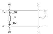
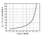
一方で、出力ミラーの反射率を低くしすぎると、却って弊害が生じる虞がある。図21に、2方向励起方式における出力ミラーの反射率に対するレーザ出力の変化を、図22に、出力ミラーの反射率に対する共振器内部エネルギーの変化を、それぞれ示す。 On the other hand, if the reflectivity of the output mirror is too low, there is a possibility that harmful effects may occur. FIG. 21 shows a change in laser output with respect to the reflectivity of the output mirror in the two-way excitation method, and FIG. 22 shows a change in resonator internal energy with respect to the reflectivity of the output mirror.
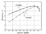
図21から、出力ミラーの反射率は70〜80%程度で最大出力を与えることが判る。また50〜60%でも、上記範囲の9割近くの出力を維持でき、また図22から共振器内部に閉じ込められるエネルギーを低く抑えることができる。このことから、共振器内部エネルギーを低減する観点からは、出力ミラーの反射率を50〜60%に設定することが好ましい。 It can be seen from FIG. 21 that the output mirror gives the maximum output when the reflectance is about 70 to 80%. Further, even at 50 to 60%, an output of nearly 90% of the above range can be maintained, and the energy confined inside the resonator from FIG. 22 can be kept low. For this reason, from the viewpoint of reducing the resonator internal energy, it is preferable to set the reflectance of the output mirror to 50 to 60%.
一方で、出力ミラー反射率を一層低く30〜50%に設定したとしても、出力としては図21によれば8割以上が見込まれる上、図22から共振器内部に閉じ込められるエネルギーが一層低減できると思われることから、出力を多少犠牲にしてでも信頼性を確保するという観点からは、一見好ましい構成のように思われる。しかしながら、反射率を30%以下に設定した場合には、出力を低下させた分だけ共振器内部に閉じ込められるエネルギーを低減することができない。 On the other hand, even if the output mirror reflectivity is set to a lower value of 30 to 50%, the output is expected to be 80% or more according to FIG. 21, and the energy confined inside the resonator can be further reduced from FIG. From the viewpoint of ensuring reliability even if the output is somewhat sacrificed, it seems to be a preferable configuration at first glance. However, when the reflectance is set to 30% or less, the energy confined inside the resonator cannot be reduced by the amount that the output is reduced.
特に、このように低い反射率を選択した場合には、最大励起パワーではある程度の出力を確保できたとしても、励起パワーを段階的に変化させる場合や、低出力で出力を変化させた場合に問題となる。一般には出力ミラー反射率の設計は、最大励起パワー=最大出力発生時と仮定して、このデータを元にして決定される。しかしながら実際のレーザ加工装置は常に最大出力で使用される訳でなく、これ以下の異なる励起範囲でも使用される。このような場合に、出力ミラー反射率が極端に低い場合には、レーザ発振閾値が上がってしまうという弊害が生じる。図23に、図18に比べビームスプリッタの反射率を大きくした場合(50%)と小さくした場合(3%)における、励起光源のLDのパワーに対するレーザ出力光のパワーを測定したグラフを示す。この図に示すように、反射率が低くなるとレーザ出力光が得られる励起光のレーザ発振閾値が約13Wから20Wに上昇している。これは、LDユニットのパワーが低い方が固体レーザ媒質内部のゲインが下がる、すなわち励起密度が下がるため、結果として最適な出力ミラー反射率が、LDユニットのパワーが高い場合と比較して相対的に大きくなってしまうためである。このためLDユニットのパワーが低い場合には、最適な反射率の設計からはずれ、効率の悪い発振を強いられることとなる。このような発振効率の場合には、出力が不安定になり、温度やミラーコーティングの経時劣化によるレーザ出力光の変化が大きくなるという問題が発生する。このため、出力ミラー反射率を極度に下げすぎると総体的にメリットが得られないことになる。このような点を勘案すると、出力ミラーの反射率は30%〜70%の範囲が好ましいといえる。より好ましくは、40%〜50%とする。
(出力ミラーの反射率を低減させる利点)
In particular, when such a low reflectance is selected, even if a certain level of output can be secured at the maximum excitation power, when the excitation power is changed stepwise or when the output is changed at a low output It becomes a problem. In general, the design of the output mirror reflectivity is determined based on this data on the assumption that the maximum excitation power is equal to the maximum output generation time. However, an actual laser processing apparatus is not always used at the maximum output, and is also used in a different excitation range below this. In such a case, when the output mirror reflectivity is extremely low, there is a problem that the laser oscillation threshold is increased. FIG. 23 shows a graph in which the power of the laser output light is measured with respect to the power of the LD of the excitation light source when the reflectivity of the beam splitter is increased (50%) and decreased (3%) compared to FIG. As shown in this figure, the laser oscillation threshold value of the excitation light from which the laser output light can be obtained increases from about 13 W to 20 W when the reflectance decreases. This is because the gain inside the solid-state laser medium decreases when the power of the LD unit is low, that is, the pumping density decreases. As a result, the optimum output mirror reflectivity is relative to the case where the power of the LD unit is high. This is because it becomes larger. For this reason, when the power of the LD unit is low, the optimum reflectance is not designed, and inefficient oscillation is forced. In the case of such oscillation efficiency, the output becomes unstable, and there arises a problem that the change in laser output light due to temperature and mirror coating deterioration with time increases. For this reason, if the output mirror reflectivity is excessively lowered, the overall merit cannot be obtained. Considering this point, it can be said that the reflectance of the output mirror is preferably in the range of 30% to 70%. More preferably, it is 40% to 50%.
(Advantage of reducing output mirror reflectivity)
ここで、レーザ出力Pの計算式を検討する。出力ミラーの透過率をT、共振器内部損失をLoss、固体レーザ媒質の断面積(有効励起断面積)をA、固体レーザ媒質の結晶長さ(有効励起長さ)をLとし、また固体レーザ媒質内部に発生する小信号利得をg0、飽和定数をIs(=hν/δτf)とする。このときレーザ出力Pは次の数1によって表現される。
[数1]
P=T・(T+Loss)・A・Is・g0・L−T・A・Is/2
Here, the calculation formula of the laser output P is examined. The transmittance of the output mirror is T, the internal loss of the resonator is Loss, the cross-sectional area of the solid-state laser medium (effective pumping cross-sectional area) is A, the crystal length of the solid-state laser medium (effective pumping length) is L, and the solid-state laser The small signal gain generated in the medium is g 0 , and the saturation constant is Is (= hν / δτ f ). At this time, the laser output P is expressed by the following equation (1).
[Equation 1]
P = T · (T + Loss) · A · Is · g 0 · L−T · A · Is / 2
上記数1をTの方程式と考えると、極大値を与えるToptのとき、出力ミラーから取り出せるパワーが最大となる。よってToptを計算すると、次式数2のようになる。
[数2]
Topt=((sqrt(2・g0・L/Loss)−1)Loss
Considering the
[Equation 2]
T opt = ((sqrt (2 · g 0 · L / Loss) −1) Loss
数2より、小信号利得g0が大きい方が最適な出力ミラーの透過率Toptも大きくなり、よって出力ミラーの反射率Rが小さくなる。以上から、小信号利得g0が大きくなるような設計をすれば、最も効率よくエネルギーを取り出せる出力ミラーの反射率Rを小さくできる。一方で、出力ミラーの反射率R、出力ミラーから取り出せる出力をXとすると、共振器内部に閉じ込められるパワーは、図20に示すように次式数3で表現できる。
[数3]
(1+R)・X/(1−R)
From
[Equation 3]
(1 + R) · X / (1-R)
このことから、出力ミラーの反射率Rが小さいほど、共振器内部に閉じ込められるエネルギーは小さくなり、出力ミラーやリア側ミラー、固体レーザ媒質端面におけるコーティング損傷のリスクは小さくなることが判る。 From this, it can be seen that the smaller the reflectivity R of the output mirror, the smaller the energy confined inside the resonator, and the lower the risk of coating damage on the output mirror, rear side mirror, and solid laser medium end face.
一方、上記小信号利得g0は次式数4によって表現される
[数4]
g0=σ・N0・Wp・τf
On the other hand, the small signal gain g 0 is expressed by the following equation (4).
g 0 = σ · N 0 · Wp · τ f
上式において、σは誘導放出断面積、τfは蛍光寿命でいずれも物性値であり、固体レーザ媒質の種類(Nd:YVO4かNd:YLFかなど)によって決まる。一方、N0、Wpはそれぞれ単位体積に存在する励起源(原子数)のポンピングレートを意味し、その積N0・Wpは励起される原子の単位時間・単位体積当たりの数を意味することになる。よって、g0の大きなレーザ加工装置を設計するには、励起光を小さなボリュームに集光して励起し、単位体積内で励起される原子数を増やせばよいことになり、励起密度を上げればg0が大きいということに繋がる。これにより、励起ボリュームが小さくなるように設計し、励起密度を上げて励起を行えばg0が大きくなり、結果として出力ミラーの反射率を下げても、出力ミラーより効率的にレーザの取り出しが行えるようになる。これによって、共振器を構成する光学部材に使われているコーティングが損傷するリスクを低減できる。 In the above equation, σ is a stimulated emission cross-sectional area, and τ f is a fluorescence lifetime, both of which are physical property values, which are determined by the type of solid-state laser medium (Nd: YVO 4 or Nd: YLF, etc.). On the other hand, N 0 and Wp mean the pumping rate of the excitation source (number of atoms) existing in the unit volume, and the product N 0 · Wp means the number of excited atoms per unit time and unit volume. become. Therefore, in order to design a laser processing apparatus with a large g 0 , it is only necessary to increase the number of atoms excited in a unit volume by concentrating excitation light on a small volume and increasing the excitation density. g 0 leads to the fact that large. As a result, if the excitation volume is designed to be small and the excitation density is increased and excitation is performed, g 0 increases, and as a result, even if the output mirror reflectance is lowered, the laser can be extracted more efficiently than the output mirror. You can do it. As a result, the risk of damage to the coating used in the optical member constituting the resonator can be reduced.
以上の観点からは、励起密度を上げる設計が好ましいことになる。しかしながら、固体レーザ媒質内部に発生する熱レンズのために、現実には上記した計算式通りの出力が得られない。固体レーザ媒質内部に発生した熱レンズはモードを悪化させたり、場合によっては共振器の安定動作を妨げ、レーザが発振しないケースも生じ得る。よって、熱レンズの発生量が同一であるという前提のもとでは、上記理論に基づいて励起密度を高めるのが好ましいといえる。特に、従来の1方向励起に比べ2方向励起の方が、励起光を分散させることによってトータルの熱レンズ発生量を低下できる。これにより、2方向励起では、励起密度を高めても、従来の1方向励起と同等の熱レンズ発生状態を実現することが可能となり、その分出力ミラーの反射率を抑えることが可能となる。このように、2方向励起を用いて熱を分散させ、その分高い密度で励起することが可能となり、さらにこれによって出力ミラーの反射率を抑えることができ、共振器内部に蓄積されるエネルギーを抑制できる。
(モードマッチング)
From the above viewpoint, a design that increases the excitation density is preferable. However, because of the thermal lens generated inside the solid-state laser medium, the output according to the above calculation formula cannot actually be obtained. The thermal lens generated inside the solid-state laser medium may deteriorate the mode, and in some cases, the stable operation of the resonator may be hindered and the laser may not oscillate. Therefore, it can be said that it is preferable to increase the excitation density based on the above theory under the assumption that the generation amount of the thermal lens is the same. In particular, compared with the conventional one-way excitation, the two-way excitation can reduce the total amount of generated thermal lenses by dispersing the excitation light. Thereby, in the two-way excitation, even if the excitation density is increased, it is possible to realize a thermal lens generation state equivalent to the conventional one-way excitation, and it is possible to suppress the reflectance of the output mirror correspondingly. In this way, it is possible to dissipate heat using two-way excitation and excite it by a correspondingly high density, which can further reduce the reflectivity of the output mirror, and reduce the energy accumulated in the resonator. Can be suppressed.
(Mode matching)
さらに、2方向励起において励起光のスポット径を、固体レーザ媒質の有するTEM00ビームモードよりも小さくすることで、一層の高効率化を図ることができる。従来の2方向励起においては、固体レーザ媒質の各端面に対して、照射する励起光のスポット径を、固体レーザ媒質の持つTEM00モード径のサイズより若干大きくすることで、励起が励起が狭い範囲に集中して熱レンズや強熱レンズ効果が発生する問題を回避していた。しかしながらこの方法では、LDユニットの出力が低い場合には対応できても、高出力のLDユニットを使用する場合においては固体レーザ媒質結晶内でのゲインの増大を図ることが困難であった。そこで、共振器内部に発生するTEM00モードよりも細い励起スポット径として強密度励起することで、固体レーザ結晶内部に発生するゲインを増大させる。 Further, by making the spot diameter of the excitation light smaller than the TEM 00 beam mode of the solid-state laser medium in the two-way excitation, it is possible to further increase the efficiency. In the conventional bi-directional excitation, the excitation is narrowly excited by slightly increasing the spot diameter of the excitation light to be irradiated on each end face of the solid-state laser medium from the size of the TEM 00 mode diameter of the solid-state laser medium. The problem that the thermal lens and the hot lens effect are generated by concentrating on the range was avoided. However, this method can cope with the case where the output of the LD unit is low, but it is difficult to increase the gain in the solid-state laser medium crystal when the high output LD unit is used. Therefore, the gain generated inside the solid-state laser crystal is increased by performing high-density excitation with an excitation spot diameter narrower than the TEM 00 mode generated inside the resonator.
より詳細に説明すると、TEM00ビームモードとは、単一波長を発振できるモード(シングルモード)であり、このモードでレーザ発振させることでレーザ出力光の位相が揃い、乱れのない高品質な出力光を得ることができる。TEM00モードを得るためには、アパーチャ等を用いて、固体レーザ媒質の端面でTEM00モードの領域のみを励起する。ここで従来の発想では、狭い領域で励起させると熱レンズが発生し易いと考えられていた。また一旦熱レンズが発生すると、アパーチャ等で集光させてTEM00モードとしても、熱レンズ効果によって出力光が広がってしまう。このことから、TEM00モードよりも若干大きく励起して熱レンズ等を回避すること行われていた。ただ、広い領域で励起するとシングルモードからマルチモードが混在するようになる。一方でスポット径を細くして励起すると、上述の通り熱レンズが発生し、シングルモードが得られなくなる。例えば2〜3W程度といった出力の低いレーザ加工装置であれば、細く励起してもシングルモードが得られる。しかしながら、10Wクラスの出力になると、細く励起すると熱の影響によりシングルモードが得られない。そこで、上述の通り2方向励起方式を採用することで、熱の集中を緩和させ、この結果細いスポット径で励起しても、シングルモードで励起できるようになる。以上のように、2方向励起とスポット径の調整を併用することで、必要な領域のみを強調して励起し、高効率で高品質なレーザ出力光を得ることができる。例えば従来の方式では、30WのLDユニットの入力で9Wの共振器出力を得ていたのに対し、本実施の形態では2方向励起とモードマッチングの組み合わせにより効率を改善し、40WのLDユニットの入力で平均出力10W以上、ピークパワー30kW以上の共振器出力を得ることができる。さらに、平均出力を15W、ピークパワーを100kWとすることもできる。
さらにTEM00モードのスポット径を1.3以下としてシングルモード出力を可能としており、加えてレーザ出力光が0.5W〜15Wのすべての出力範囲でTEM00モードのスポット径1.3以下に抑えることができる。
More specifically, the TEM 00 beam mode is a mode that can oscillate a single wavelength (single mode). By oscillating laser in this mode, the phase of the laser output light is aligned and high quality output without disturbance Light can be obtained. To obtain a TEM 00 mode, using an aperture or the like, to excite only the area of the TEM 00 mode at the end face of the solid-state laser medium. Here, according to the conventional idea, it is considered that a thermal lens is likely to be generated when excited in a narrow region. Also, once a thermal lens is generated, the output light spreads due to the thermal lens effect even if it is condensed by an aperture or the like and set in the TEM 00 mode. For this reason, it has been practiced to avoid a thermal lens by exciting slightly larger than the TEM 00 mode. However, when excited over a wide area, single mode to multi-mode are mixed. On the other hand, if the spot diameter is reduced and excited, a thermal lens is generated as described above, and a single mode cannot be obtained. For example, if the laser processing apparatus has a low output of about 2 to 3 W, a single mode can be obtained even if it is excited finely. However, when the output is 10 W class, a single mode cannot be obtained due to the influence of heat if it is excited finely. Therefore, by adopting the two-way excitation method as described above, the concentration of heat is alleviated. As a result, even if excitation is performed with a narrow spot diameter, excitation can be performed in a single mode. As described above, by using two-way excitation and spot diameter adjustment in combination, it is possible to enhance and excite only a necessary region, and to obtain high-efficiency and high-quality laser output light. For example, in the conventional method, a 9 W resonator output is obtained at the input of the 30 W LD unit, but in this embodiment, the efficiency is improved by combining two-way excitation and mode matching, and the 40 W LD unit is improved. A resonator output with an average output of 10 W or more and a peak power of 30 kW or more can be obtained at the input. Further, the average output can be 15 W and the peak power can be 100 kW.
Furthermore, the TEM 00 mode spot diameter is 1.3 or less to enable single mode output. In addition, the laser output light is suppressed to a TEM 00 mode spot diameter of 1.3 or less in the entire output range of 0.5 W to 15 W. be able to.
スポット径の調整は、集光レンズで行う。集光レンズは、反射ミラーで反射された、あるいは分岐手段23で反射乃至透過された平行光を所定のスポット径に集光して、固体レーザ媒質の端面に投入する。
(レーザ光走査系30)
The spot diameter is adjusted with a condenser lens. The condensing lens condenses the parallel light reflected by the reflecting mirror or reflected or transmitted by the branching means 23 to a predetermined spot diameter, and puts it on the end face of the solid-state laser medium.
(Laser beam scanning system 30)
以上のようにしてレーザ共振部で生成されたレーザ出力光を、レーザ光走査系30で所望の加工パターンにてワークW上の作業領域内に走査して、加工を行う。レーザ共振部20とレーザ光走査系30は光学的に接続されており、例えば図3において出力ミラー26から出射されるレーザ出力光を折り返して、下方に配置したレーザ光走査系30に伝送する。
Processing is performed by scanning the laser output light generated by the laser resonator as described above into a work area on the workpiece W with a desired processing pattern by the laser
レーザ光走査系30は、レーザ光を反射させて所望の方向に出力し、ワークWの表面でレーザ出力光を走査して加工するためのスキャナを備える。各スキャナは、光を反射する反射面として全反射ミラーであるガルバノミラーと、ガルバノミラーを回動軸に固定して回動するためのガルバノモータと、回動軸の回転位置を検出して位置信号として出力する位置検出部を備える。またスキャナは、スキャナを駆動するスキャナ駆動部35に接続される。スキャナ駆動部35は制御部50に接続され、スキャナを制御する制御信号を制御部50から受けて、これに基づいてスキャナを駆動する。例えばスキャナ駆動部35は、制御信号に基づいてスキャナを駆動する駆動電流を調整する。またスキャナ駆動部35は、制御信号に対する各スキャナの回転角の時間変化を調整する調整機構を備える。調整機構は、スキャナ駆動部35の各パラメータを調整する可変抵抗等の半導体部品で構成される。
The laser
図1に示すレーザ光走査系30は、一対のX軸スキャナ31、Y軸スキャナ32と、これらをそれぞれ回動するガルバノモータ33、34とを備えている。ガルバノモータ33、34は、スキャナ駆動部35で駆動される。スキャナ駆動部35は、制御部50から与えられる走査信号に基づいて、ガルバノモータ33、34を駆動させることにより、ガルバノモータ33、34の出力軸に設けられたX軸スキャナ31、Y軸スキャナ32の全反射ミラーを回動させて、固体レーザ媒質21から発振されたレーザ出力光を偏向・走査する。偏向・走査されたレーザ出力光は、略偏向方向に設けられた作業領域集光部40を介してワークWの表面に照射されてマーキングする。作業領域集光部40は、スキャナがニュートラル位置にある状態において偏向されたレーザ出力光がその中央を平行光として入射されるように設けられている。
The laser
作業領域集光部40は、fθレンズ等の作業領域集光レンズが使用される。レーザビームは、ガルバノミラーにより反射された後、作業領域集光レンズにより集光して照射面に照射されるが、小スポットへの集光を効果的に行わせるため、図1に示すようにガルバノミラーにビームエキスパンダ36を前置し、レーザ発振部50から出力されるレーザビームのビーム径を拡げるようにしている。ビームエキスパンダ36からの出射ビームは、ミラーなどの光学部材により反射してレーザ光走査系30のガルバノミラーに導かれる。なおfθレンズ等の作業領域集光部は、後述するようにZ軸スキャナにその機能を代用させて、省略することもできる。
The work
レーザ光走査系30の一例を図24、図25、図26に示す。これらの図において、図24はレーザ加工装置のレーザ光走査系30の構成を示す斜視図を、図25は図24を逆方向から見た斜視図を、図26は側面図を、それぞれ示している。これらの図に示すレーザ加工装置は、レーザ出力光を発生させるレーザ共振部20と光路を一致させたZ軸スキャナを内蔵するビームエキスパンダ36と、X軸スキャナ31と、X軸スキャナ31と直交するよう配置されたY軸スキャナ32とを備える。このレーザ光走査系30は、レーザ共振部20より出射されるレーザ出力光をX軸スキャナ31、Y軸スキャナ32で作業領域WS内で2次元的に走査させ、さらにZ軸スキャナ37で高さ方向にワーキングディスタンスすなわち焦点距離を調整することができ、3次元状に加工加工が可能となる。なお、X軸スキャナ、Y軸スキャナ、Z軸スキャナは、互いに入れ替えても同様に機能できることはいうまでもない。例えばZ軸スキャナを出射したレーザ出力光をY軸スキャナで受けるよう構成したり、あるいはX軸スキャナでY軸を制御し、Y軸スキャナでZ軸を制御するよう配置してもよい。なおこれらの図においては、作業領域集光レンズであるfθレンズは図示を省略している。
An example of the laser
レーザ加工装置においては一般に、Y軸スキャナで反射されたレーザ出力光を作業領域に照射させるよう集光するために、Y軸スキャナと作業領域の間には、fθレンズ等の作業領域集光レンズを配置している。fθレンズは、Z軸方向の補正を行う。具体的には、図27(a)に示すように、作業領域WSの端部に近付くほど焦点位置を伸ばし、ワークWの加工対象面上に位置させる補正である。レーザ出力光の焦点位置は円弧状の軌跡となるため、加工対象面が平面の場合、鉛直下の位置、図27(a)において加工対象面を示す平面WMの中心で焦点位置が合うように設定すると、中心から離れるほど、すなわち作業領域WSの周辺に近付くほど焦点位置が加工対象面から遠ざかり(レーザ出力光LB’)、焦点が合わず加工精度が低下する。そこで、図27(b)に示すように作業領域WSの端部に近付くほどレーザ出力光LBの焦点位置が長くなるよう、fθレンズで補正する。仮想的に加工対象面の平面WMが、WM’で示す凸状曲面の補正面となるよう変換することで、レーザ出力光LBの焦点位置を平面WM上に位置させることができる。 In general, in a laser processing apparatus, a work area condensing lens such as an fθ lens is provided between the Y axis scanner and the work area in order to collect the laser output light reflected by the Y axis scanner so as to irradiate the work area. Is arranged. The fθ lens performs correction in the Z-axis direction. Specifically, as shown in FIG. 27A, the focal position is extended as it approaches the end of the work area WS, and is corrected to be positioned on the processing target surface of the workpiece W. Since the focus position of the laser output light is an arc-shaped locus, when the processing target surface is a plane, the focus position is adjusted so that the focus position is at a position vertically below, the center of the plane WM indicating the processing target surface in FIG. When set, the farther away from the center, that is, the closer to the periphery of the work area WS, the farther the focal position is from the surface to be processed (laser output light LB ′), and the processing accuracy is lowered because the focus is not achieved. Therefore, as shown in FIG. 27 (b), correction is performed by the fθ lens so that the focal position of the laser output light LB becomes longer as it approaches the end of the work area WS. The focal position of the laser output light LB can be positioned on the plane WM by virtually converting the plane WM of the processing target surface into a convex curved correction surface indicated by WM ′.
レーザ加工装置において、例えばスポット径を約50μmより小さいビームを形成したい場合は、fθレンズを配置することが好ましい。一方、上述の小スポット径よりも大きい、スポット径が約100μm程度(通常良く使用されるスポット径)のビーム径を採用する場合は、Z軸スキャナ側のビームエキスパンダに備えられたZ軸集光レンズをZ軸方向に移動させることにより、fθレンズが行うべきZ軸方向の補正を、補正制御として行うことができる。これにより、スポット径が大きい場合はfθレンズを省略することも可能となる。上述した図27(a)の例では、fθレンズが行うべきZ軸方向の補正を、Z軸スキャナの補正制御に行わせている。一方、スポット径が小さい場合は、Z軸スキャナによる補正では焦点位置の調整が不十分となるため、上述の通りfθレンズを用いる。本実施の形態では、レーザ出力光のスポット径として小スポット、標準、ワイドスポットの3種類を用意しており、この内の小スポットタイプのみ、fθレンズで作業領域WS端部の歪みを矯正し、標準及びワイドスポットではfθレンズを使用せず、Z軸スキャナで補正している。 In the laser processing apparatus, for example, when it is desired to form a beam having a spot diameter smaller than about 50 μm, it is preferable to arrange an fθ lens. On the other hand, when a beam diameter larger than the small spot diameter described above and having a spot diameter of about 100 μm (usually used spot diameter) is adopted, the Z-axis assembly provided in the beam expander on the Z-axis scanner side is used. By moving the optical lens in the Z-axis direction, correction in the Z-axis direction that should be performed by the fθ lens can be performed as correction control. Thereby, when the spot diameter is large, the fθ lens can be omitted. In the example of FIG. 27A described above, correction in the Z-axis direction to be performed by the fθ lens is performed by correction control of the Z-axis scanner. On the other hand, when the spot diameter is small, the focus position is not sufficiently adjusted by the correction by the Z-axis scanner, so the fθ lens is used as described above. In this embodiment, there are three types of spot diameters of laser output light: small spot, standard, and wide spot. Only the small spot type of these is used to correct distortion at the end of the work area WS with the fθ lens. In standard and wide spots, the fθ lens is not used, and correction is performed by a Z-axis scanner.
Z軸スキャナのビームエキスパンダに備えられたZ軸集光レンズでZ軸方向の補正制御を行う場合も、上述したfθレンズによる補正と同様の補正を行う。図27(b)で説明した補正面WM’の高さ、すなわちZ座標は、XY座標によって一義的に決定される。このため、XY座標毎に、補正後のZ座標を関連付けておくことで、XY軸スキャナの移動に従いZ軸スキャナを関連付けられたZ座標に移動させれば、常に焦点位置での加工が可能となる。関連付けのデータは、図28に示すレーザ加工データ設定装置の記憶部72で保存する。あるいはレーザ加工装置のレーザ制御部1に備えられたメモリ部52に保存、転送することもできる。これによって、作業領域内におけるXY座標の移動に追従して、補正後のZ座標が決定されるので、作業領域内でほぼ均一に焦点位置が調整されたレーザ出力光を照射できる。
(Z軸スキャナ37)
Even when correction control in the Z-axis direction is performed by the Z-axis condenser lens provided in the beam expander of the Z-axis scanner, correction similar to the correction by the fθ lens described above is performed. The height of the correction surface WM ′ described in FIG. 27B, that is, the Z coordinate is uniquely determined by the XY coordinate. Therefore, by associating the corrected Z coordinate for each XY coordinate, if the Z-axis scanner is moved to the associated Z-coordinate according to the movement of the XY-axis scanner, processing at the focal position can always be performed. Become. The association data is stored in the
(Z-axis scanner 37)
Z軸スキャナ37はレーザ出力光のスポット径を調整し、これによって焦点距離を調整するビームエキスパンダ36を構成している。すなわち、ビームエキスパンダ36で入射レンズと出射レンズとの相対距離を変化させることでレーザ出力光のビーム径を拡大/縮小し、焦点位置も変化させることができる。ビームエキスパンダ36は、小スポットへの集光を効果的に行わせるため、図24に示すようにガルバノミラーの前段に配置され、レーザ共振部20から出力されるレーザ出力光のビーム径を調整すると共に、レーザ出力光の焦点位置を調整可能としている。Z軸スキャナ37がワーキングディスタンスを調整する方法を、図29〜図31に基づいて説明する。図29、図30はレーザ光走査系30の側面図であり、図29はレーザ出力光の焦点距離を長くする場合、図30は焦点距離を短くする場合をそれぞれ示している。また図31はZ軸スキャナ37の正面図及び断面図を示している。これらの図に示すように、Z軸スキャナ37はレーザ共振部20側に面する入射レンズ38と、レーザ出射側に面する出射レンズ39を含んでおり、これらのレンズ間の距離を相対的に変化可能としている。図29〜図31の例では、出射レンズ39を固定し、入射レンズ38を光軸方向に沿って駆動モータ等で摺動可能としている。図31は出射レンズ39の図示を省略して、入射レンズ38の駆動機構を示している。この例では、コイルと磁石によって軸方向に可動子を摺動可能とし、可動子に入射レンズ38を固定している。ただ、入射レンズ側を固定して出射レンズ側を移動可能としたり、入射レンズ、出射レンズを共に移動可能とすることもできる。
The Z-
図29に示すように、入射レンズ38と出射レンズ39との間の距離を近付けると、焦点位置が遠ざかり、焦点距離(ワーキングディスタンス)が大きくなる。逆に図30に示すように入射レンズ38と出射レンズ39との距離を離すと、焦点位置が近付き焦点距離が小さくなる。
As shown in FIG. 29, when the distance between the
なお、3次元加工、すなわちワークの高さ方向への加工が可能なレーザ加工装置は、上記図29、図30のようにZ軸スキャナを調整する方式の他、例えば物理的に作業領域集光レンズを移動させる、あるいはレーザ出力部やマーキングヘッド自体を移動可能とする、ワークを載置するステージを移動させる等、他の方式を利用することも可能である。
(ディスタンスポインタ)
Note that the laser processing apparatus capable of three-dimensional processing, that is, processing in the height direction of the workpiece, is not limited to the method of adjusting the Z-axis scanner as shown in FIGS. It is also possible to use other methods such as moving the lens, moving the laser output unit or the marking head itself, or moving the stage on which the workpiece is placed.
(Distance pointer)
また、3次元加工可能なレーザ加工装置の作業領域の中心に焦点位置を調整するために、レーザ出力光を作業領域WS内に走査させる際の照射位置を示すガイドパターンを表示することができる。図24〜図25に示すレーザ加工装置のレーザ光走査系30は、ディスタンスポインタとして、ガイド用光源64と、ガイド用光源64からのガイド光GLをレーザ光走査系30の光軸と一致させるためのガイド光光学系の一形態としてハーフミラー65を備えると共に、ポインタ光調整系として、ポインタ光PLを照射するためのポインタ用光源66と、Y軸スキャナ32の裏面に形成されたポインタ用スキャナミラー68と、ポインタ用スキャナミラー68で反射されたポインタ用光源66からのポインタ光PLをさらに反射させて焦点位置に向かって照射する固定ミラー67とを備えている。このディスタンスポインタは、レーザ出力光の焦点位置を示すポインタ光PLをポインタ用光源66から照射し、ガイド光GLで表示されるガイドパターンのほぼ中心に、ポインタ光PLを照射するよう調整することで、レーザ出力光の焦点位置が指示される。
Further, in order to adjust the focal position at the center of the work area of the laser processing apparatus capable of three-dimensional processing, a guide pattern indicating the irradiation position when the laser output light is scanned into the work area WS can be displayed. The laser
なお、上記の例ではレーザ光走査系30に、レーザ出力光の焦点距離を調整可能な機構を設けることで3次元加工を可能としている。ただ、ワークを載置するステージの位置を上下方向に調整可能とすることで、レーザ出力光の焦点がワークの作業面で結ぶようにステージの高さを調整する制御を行うことでも、同様に3次元加工を行うこともできる。また、ステージをX軸あるいはY軸方向に移動可能とすることで、レーザ光走査系の該当するスキャナを省略できる。これらの構成は、ワークをライン上に搬送する形態でなく、ステージ上に載置して加工する形態において好適に利用できる。
In the above example, the laser
以上の構成によれば、レーザ光走査系30によってレーザ共振器で得られたレーザ出力光を作業領域内において3次元的に走査させることができる。またXY軸スキャナに比べ、一般に応答特性の劣るZ軸スキャナの移動量を抑えることで、より高速で制御性の高い3次元加工が可能となる。さらに作業領域の各位置での焦点距離を一定に維持するようZ軸スキャナで補正しつつ、レーザ出力光の出射がOFFの間はこの補正を中断して、XY軸スキャナに比べ、一般に応答特性の劣るZ軸スキャナの移動量を抑えることができ、より高速で制御性の高い3次元加工が可能となる。さらにまた、作業領域内で焦点位置がほぼ均一になるようにZ軸スキャナで調整され、別途作業領域集光レンズ等を用意せずとも作業領域端縁近傍での加工精度低下を防止できる。加えて、次回の加工開始位置のZ座標を先読みして、この位置に移動させておくことにより次回の加工開始をスムーズに行わせることができる。あるいは、Z軸スキャナの追従動作を中断して一定の位置に保持できるので、XY軸スキャナはZ軸スキャナの応答時間に左右されることなく高速に次の加工位置まで移動でき、全体としての走査速度向上が図られる。
According to the above configuration, the laser output light obtained by the laser resonator by the laser
また一方で、固体レーザ媒質の熱レンズ特性により、出射光の拡がり角度が変わるため、加工点での焦点位置がパワーの設定によりずれるという問題が生じる。このずれを演算することで、Z軸スキャナでずれを補正し、熱レンズが発生しても高精度な加工を維持できる。
(レーザ加工装置のシステム構成)
On the other hand, since the spread angle of the emitted light changes due to the thermal lens characteristics of the solid-state laser medium, there arises a problem that the focal position at the processing point is shifted due to the power setting. By calculating this deviation, the deviation is corrected by the Z-axis scanner, and high-precision processing can be maintained even if a thermal lens is generated.
(System configuration of laser processing equipment)
次に図32に、3次元加工可能なレーザ加工装置のシステム構成を示す。この図に示すレーザ加工システムは、レーザ出力部を構成するマーキングヘッド2Aと、マーキングヘッド2Aと接続されてこれを制御するレーザ制御部1であるコントローラ1Aと、コントローラ1Aとデータ通信可能に接続され、コントローラ1Aに対して加工パターンを3次元のレーザ加工データとして設定するレーザ加工データ設定装置70とを備える。このマーキングヘッド2Aとコントローラ1Aとで、レーザ加工装置100が構成される。またレーザ加工データ設定装置70は、図32の例においてはコンピュータにレーザ加工データ設定プログラムをインストールして、レーザ加工データ設定機能を実現させている。レーザ加工データ設定装置は、コンピュータの他、タッチパネルを接続したプログラマブルロジックコントローラ(PLC)や、その他専用のハードウェア等を利用することもできる。またレーザ加工データ設定装置は、レーザ加工装置の動作を制御する制御装置として機能させることもできる。例えば、一のコンピュータにレーザ加工データ設定装置としての機能と、レーザ出力部を備えるレーザ出力部のコントローラとしての機能を統合してもよい。さらにレーザ加工データ設定装置は、レーザ加工装置と別部材で構成する他、レーザ加工装置に統合することもでき、例えばレーザ加工装置に組み込まれたレーザ加工データ設定回路等とすることもできる。
Next, FIG. 32 shows a system configuration of a laser processing apparatus capable of three-dimensional processing. The laser processing system shown in this figure is connected to a marking
さらにコントローラ1Aには、必要に応じて各種外部機器80を接続できる。例えばライン上に搬送されるワークの種別、位置等を確認するイメージセンサ等の画像認識装置、ワークとマーキングヘッド2Aとの距離に関する情報を取得する変位計等の距離測定装置、所定のシーケンスに従って機器の制御を行うPLC、ワークの通過を検出するPDセンサその他各種のセンサ等を設置し、これらとデータ通信可能に接続できる。
(レーザ加工データ設定装置)
Furthermore, various
(Laser processing data setting device)
平面状の加工データを3次元状に加工するための設定情報であるレーザ加工データは、レーザ加工データ設定装置70により設定される。図28は、レーザ加工データ設定装置70の一例としてブロック図を示している。この図に示すレーザ加工データ設定装置70は、各種設定を入力するための入力部4と、入力部4から入力された情報に基づいてレーザ加工データを生成する加工データ生成手段を構成する演算部71と、設定内容や演算後のレーザ加工データを表示するための表示部5と、各種設定データを記憶するための記憶部72とを備える。表示部5は、加工対象面のイメージを3次元的に表示可能な加工イメージ表示部と、加工イメージ表示部に加工対象面のイメージを3次元的に表示させる際に、マーキングヘッド2Aのイメージを表示可能なヘッドイメージ表示手段を備える。入力部4は、所望の加工パターンで加工する加工条件を入力するための加工条件設定部として、ワークの加工面の3次元形状を示すプロファイル情報を入力するための加工面プロファイル入力手段と、加工パターン情報を入力するための加工パターン入力手段と、作業領域内に複数の加工ブロックを設定し、加工ブロック毎に加工パターンを設定可能な加工ブロック設定手段と、ブロック設定手段で設定された複数の加工ブロックを纏めた加工グループを設定するためのグループ設定手段、加工対象面上に配置される加工パターンの位置を調整可能な位置調整手段の機能を実現する。加工面プロファイル入力手段はさらに、加工対象面を表す基本図形を指定するための基本図形指定手段と、加工対象面を表す3次元形状データを外部から入力するための3次元形状データ入力手段の機能を実現する。記憶部72は、図1のメモリ部52に相当し、入力部4で設定されたプロファイル情報や加工パターン情報等の情報を記憶する部材であり、固定記憶装置等の記憶媒体や半導体メモリ等が利用できる。表示部5は、専用のディスプレイを設ける他、システムに接続されたコンピュータのモニタを利用してもよい。このレーザ加工データ設定装置70により設定された加工条件として、加工パワー(レーザ出力)やスキャンスピード(走査速度)の他、必要に応じてワーキングディスタンス、デフォーカス量、スポット径、ワークの種別(鉄への黒色加工、ステンレスへの黒色加工、ABS樹脂、ポリカーボネート樹脂、フェノール樹脂といったワークの材質、及び樹脂溶着、表面粗しといった加工目的)等を設定する。また複数の加工ブロックを設定し、加工ブロック単位で加工パターン情報を設定してもよい。特に、立ち上がり特性に優れたレーザ出力光を達成できるレーザ加工装置においては、加工ブロック毎に加工対象のワークの材質、加工パターン、仕上げ状態、加工時間等の設定項目について、レーザ出力光のパワーやビーム径を自由に変化させることができる。さらに、一旦設定された加工条件の加工パラメータを設定データとして保存し、必要時に呼び出すこともできる。
Laser processing data that is setting information for processing planar processing data into a three-dimensional shape is set by a laser processing
一般のレーザ光走査系においては、スキャナの応答特性、すなわちスキャナに動作指示が与えられてから実際に動作を完了するまでに要する応答時間は、スキャナによって異なることがある。例えばX、Y、Z軸スキャナを有する3次元加工可能なレーザ加工装置においては、一般にX、Y軸スキャナに比べ、Z軸スキャナの応答特性が劣る傾向にある。例えば図24等に示すように、X・Y軸スキャナはガルバノスキャナによって回転するミラーにてスキャンするが、これに対しZ軸スキャナは光軸方向へレンズ自体を平行移動させる機構となっている。このためZ軸スキャナは、モータを利用した回転運動を平行移動に変換させる動作機構により、Z軸スキャナの応答特性がX・Y軸スキャナに比べて不利となる。またZ軸スキャナにモータを使用せず、シリンダやピストン等で駆動することもできるが、この場合も応答速度的にはX・Y軸スキャナに比べて不利となる。この結果、Z軸スキャナ駆動用モータの応答時間がX・Y軸スキャナより後れる分、スキャナの制御に待ち時間が生じる。そこで使用するスキャナの応答特性やワークの形状等に応じて、適切な移動経路を選択するよう、制御部50が加工パターンに応じた最適な移動経路を選定する。好ましくは、応答性能の劣るスキャナの使用を可能な限り控える経路を選択することで、高速な移動が実現できる。
In a general laser beam scanning system, the response characteristics of the scanner, that is, the response time required to actually complete the operation after the operation instruction is given to the scanner may differ depending on the scanner. For example, in a laser processing apparatus capable of three-dimensional processing having an X, Y, and Z axis scanner, the response characteristics of the Z axis scanner tend to be inferior as compared to the X and Y axis scanners. For example, as shown in FIG. 24 and the like, an X / Y-axis scanner scans with a mirror rotated by a galvano scanner, whereas a Z-axis scanner has a mechanism for translating the lens itself in the optical axis direction. For this reason, the Z-axis scanner is disadvantageous in response characteristics of the Z-axis scanner compared to the X / Y-axis scanner due to the operation mechanism that converts the rotational motion using the motor into the parallel movement. The Z-axis scanner can be driven by a cylinder, a piston or the like without using a motor, but this case is also disadvantageous in terms of response speed compared to the X / Y-axis scanner. As a result, the response time of the Z-axis scanner driving motor lags behind that of the X / Y-axis scanner, so that a waiting time occurs in the scanner control. Therefore, the
また、Z軸スキャナで図27に示すような光学特性の補正を行うこともできる。すなわち、fθレンズによる焦点位置の補正をZ軸スキャナで行う場合にも、Z座標の関連付けを行ってZ軸スキャナの追従機能を利用できる。この場合においても、レーザ出力光の出射OFF時には追従機能をOFFさせることで、余計な待ち時間を省略して応答特性を改善し、加工に要する時間を短縮できる。このように、レーザ出力光の出射ON/OFFに応じてZ軸の軌跡を変化させ、特に出射OFFの際に余計なZ方向の動きを排除して処理時間を短縮でき、効率的なスキャナの駆動が実現できる。 Further, the optical characteristics can be corrected as shown in FIG. 27 with a Z-axis scanner. That is, even when the focal position is corrected by the fθ lens using the Z-axis scanner, the tracking function of the Z-axis scanner can be used by associating the Z coordinates. Even in this case, by turning off the tracking function when the output of the laser output light is turned off, an extra waiting time can be omitted, the response characteristics can be improved, and the time required for processing can be shortened. In this way, the Z-axis trajectory is changed according to the output ON / OFF of the laser output light, and the processing time can be shortened by eliminating unnecessary movement in the Z direction especially when the output is OFF. Driving can be realized.
本発明のレーザマーカは、例えばマーキング、穴あけ、トリミング、スクライビング、表面処理、材料プロセス、分光、ウェハ検査、医療診断、レーザプリント等、レーザ照射を行う処理において広く適用可能であり、半導体等の微細加工やディスプレイリペア、トリミングシステム等の用途に利用できる。 The laser marker of the present invention, for example marking, drilling, trimming, scribing, surface treatment, material processing, spectroscopy, wafer inspection, medical diagnosis, laser printing and the like, are widely applicable in the process of performing laser irradiation, the fine semiconductor such as It can be used for applications such as processing, display repair, and trimming systems.
100…レーザ加工装置
1…レーザ制御部;1A…コントローラ
2…レーザ出力部;2A…マーキングヘッド
3…励起光伝達媒体;4…入力部;5…表示部
10…レーザ励起部
11…励起光源;12…励起光集光部;13…励起ケーシング;14…光ファイバ
20、201〜208…レーザ共振部;21…固体レーザ媒質
22…励起光結合手段;22a…光ファイバ結合部;22b…コリメートレンズ
23…分岐手段
24…第1ダイクロイックミラー;25…第2ダイクロイックミラー
26…出力ミラー;27…アパーチャ;28…Qスイッチ
30…レーザ光走査系
31…X軸スキャナ;32…Y軸スキャナ;33、34…ガルバノモータ
35…スキャナ駆動部;36…ビームエキスパンダ;37…Z軸スキャナ
38…入射レンズ;39…出射レンズ
40…集光部;50…制御部
52…メモリ部;54…電源回路
61…第1集光レンズ;62…第2集光レンズ;63…構造基板
64…ガイド用光源;65…ハーフミラー;66…ポインタ用光源
67…固定ミラー;68…ポインタ用スキャナミラー
70…レーザ加工データ設定装置
71…演算部;72…記憶部;80…外部機器
901…レーザ制御部;902…レーザ出力部;904…入力部;910…レーザ励起部
918…出力カプラ;920…レーザ共振部;921…固体レーザ媒質;928…LD
930…レーザ光走査系;932…光ファイバ;936…ビームエキスパンダ
940…作業領域集光部
LB、LB’…レーザ出力光;PL…ポインタ光;GL…ガイド光
W…ワーク;WS…作業領域;WM…加工対象面を示す平面;WM’…補正面
R1…第1励起光;R2…第2励起光
B…分岐経路;B1…第1分岐経路;B2…第2分岐経路
RM…リア側ミラー;FM…出射側ミラー
BS、BS1〜BS8…ビームスプリッタ
M1、M11〜M18…第1反射ミラー
M2、M21〜M28…第2反射ミラー
M3、M31〜M38…第3反射ミラー
DESCRIPTION OF
930 ... Laser beam scanning system; 932 ... Optical fiber; 936 ...
Claims (9)
前記レーザ制御部で発生された励起光を後記レーザ出力部に伝達するための励起光伝達媒体と、
前記励起光伝達媒体で伝達された励起光に基づくレーザ発振により生成されたレーザ光を走査させるためのレーザ光走査系を含むレーザ出力部と、
を備えるレーザマーカであって、
前記レーザ出力部が、
一方向に延長され、2つの端面を有する結晶状の固体レーザ媒質であって、前記励起光伝達媒体で伝達された励起光を両端面から投入してレーザ発振を生じさせるものであり、且つ該端面として、
励起光の入射面を構成する第1端面と、
前記第1端面の反対側であって、励起光の入射面及び励起光の取り出し面を構成する第2端面と、
を備える固体レーザ媒質と、
前記励起光伝達媒体で伝達された励起光を、第1分岐経路を進む第1励起光及び第2分岐経路を進む第2励起光の2つに分岐し、前記第1分岐経路から前記固体レーザ媒質の第1端面に励起光の第1励起光を、前記第2分岐経路から第2端面に第2励起光を、第1励起光が第2励起光よりも多くなるように各々入射させる分岐手段と、
前記第1端面に対向させて第1分岐経路上に配置され、励起光を透過し且つレーザ発振光を前記第1端面側に反射させる第1ダイクロイックミラーと、
前記第2端面に対向させて第2分岐経路上に配置され、励起光を透過し且つレーザ発振光を、後記出力ミラーに向かって反射させる第2ダイクロイックミラーと、
分岐経路と干渉しない位置であって、前記第2ダイクロイックミラーから前記一方向と略直交する方向に離れた位置に配置され、前記第2ダイクロイックミラーで反射した反射光を出力するための出力ミラーと、
前記第2ダイクロイックミラーと前記出力ミラーとの間に配置され、レーザ出力のON/OFFを制御するQスイッチと、
を備え、
前記固体レーザ媒質と第1ダイクロイックミラーとの距離が、前記第2ダイクロイックミラーと出力ミラーとの間の距離よりも短く、且つ、前記第1端面に入射される第1励起光が前記第2端面に入射される第2励起光よりも多くなるように構成されてなることを特徴とするレーザマーカ。 A laser controller for generating excitation light;
An excitation light transmission medium for transmitting excitation light generated by the laser control unit to a laser output unit described later;
A laser output unit including a laser light scanning system for scanning laser light generated by laser oscillation based on excitation light transmitted by the excitation light transmission medium;
A laser marker with a,
The laser output unit,
A crystalline solid-state laser medium extending in one direction and having two end faces, wherein the pumping light transmitted by the pumping light transmission medium is input from both end faces to cause laser oscillation; and As an end face,
A first end face constituting an incident surface of excitation light;
A second end surface that is opposite to the first end surface and forms an excitation light incident surface and an excitation light extraction surface;
A solid state laser medium comprising:
Splits the pumping light transmitted by the excitation light transfer medium, the two second excitation light traveling in the first excitation light and second branch path travels first branch path, said solid state laser from the first branch path a first pump light of the first end surface to the excitation light of the medium, the second excitation light from the second branch path to a second end surface, Ru is respectively incident to first excitation light is larger than the second excitation light Branching means;
A first dichroic mirror disposed on the first branch path so as to face the first end face and transmitting excitation light and reflecting laser oscillation light toward the first end face;
A second dichroic mirror that is disposed on the second branch path so as to face the second end face, transmits excitation light, and reflects laser oscillation light toward an output mirror described later;
An output mirror that is disposed at a position that does not interfere with the branch path and is separated from the second dichroic mirror in a direction substantially orthogonal to the one direction, and for outputting reflected light reflected by the second dichroic mirror; ,
A Q switch disposed between the second dichroic mirror and the output mirror for controlling ON / OFF of laser output;
With
The distance between the solid-state laser medium and the first dichroic mirror is shorter than the distance between the second dichroic mirror and the output mirror, and the first excitation light incident on the first end face is the second end face. the laser marker characterized by comprising configured to be larger than the second excitation light is incident on.
前記分岐手段が、入射光を第1励起光と第2励起光に分岐させる比率を、略2:1〜略4:1に設定してなることを特徴とするレーザマーカ。 A laser marker according to claim 1,
The laser marker and characterized by being set to 1: the branch unit, the ratio for branching incident light into the first excitation light and second excitation light, approximately 2: 1 to approximately 4.
前記固体レーザ媒質がNd:YVO4結晶であることを特徴とするレーザマーカ。 A laser marker according to claim 1 or 2,
The laser marker, characterized in that YVO a 4 crystal: the solid-state laser medium is Nd.
前記出力ミラーの反射率が30%〜70%であることを特徴とするレーザマーカ。 A laser marker as claimed in any one of 3,
The laser marker, wherein the reflectivity of the output mirror is 30% to 70%.
前記励起光源としての半導体レーザの平均出力が10W以上であることを特徴とするレーザマーカ。 A laser marker as claimed in any one of 4,
The laser marker, wherein the average output of the semiconductor laser as the excitation light source is 10W or more.
前記第1ダイクロイックミラーに対向させて第1分岐経路上の前記固体レーザ媒質と反対側に配置され、前記第1ダイクロイックミラーを透過した励起光の第1励起光が前記第1端面に照射される際のスポット径が、前記固体レーザ媒質のTEM00モードよりも小さくなるように励起光を集光させる第1集光レンズと、
前記第2ダイクロイックミラーに対向させて第2分岐経路上の前記固体レーザ媒質と反対側に配置され、前記第2ダイクロイックミラーを透過した励起光の第2励起光が前記第2端面に照射される際のスポット径が、前記固体レーザ媒質のTEM00モードよりも小さくなるように励起光を集光させる第2集光レンズと、
を備え、
前記固体レーザ媒質の第1端面に、前記固体レーザ媒質のTEM 00 モードよりも小さいスポット径の励起光が投入され、且つ、前記固体レーザ媒質の第2端面に、前記固体レーザ媒質のTEM 00 モードよりも小さいスポット径の励起光が投入されて固体レーザ媒質が励起されるよう構成されてなることを特徴とするレーザマーカ。 A laser marker according to any one of claims 1-6, further
The first end face is irradiated with the first excitation light of the excitation light that is disposed opposite to the solid-state laser medium on the first branch path so as to face the first dichroic mirror and that has passed through the first dichroic mirror. spot diameter during comprises a first condenser lens causes condensing the excitation light to be smaller than TEM 00 mode of the solid-state laser medium,
The second end face is irradiated with the second excitation light of the excitation light that is disposed on the opposite side of the solid-state laser medium on the second branch path so as to face the second dichroic mirror and that has passed through the second dichroic mirror. spot diameter during comprises a second condensing lens causes condensing the excitation light to be smaller than TEM 00 mode of the solid-state laser medium,
Equipped with a,
The first end surface of said solid-state laser medium, the solid excitation light of a small spot diameter than the laser medium TEM 00 mode is turned, and, on the second end surface of said solid-state laser medium, TEM 00 mode of the solid-state laser medium the laser marker, wherein Rukoto such are configured to solid-state laser medium is excited is turned excitation light of a small spot diameter than.
前記レーザ出力部がさらに、
前記分岐手段で分岐された第1励起光又は第2励起光を、略垂直に反射させる第1反射ミラーと、
前記第1反射ミラーで反射された反射光又は前記分岐手段で分岐された第2励起光或いは第1励起光を、さらに略垂直方向に反射させる第2反射ミラーと、
前記第2反射ミラーで反射された反射光を、略垂直に反射させる第3反射ミラーと、
を備え、
前記第1分岐経路及び第2分岐経路で構成される分岐経路は、前記分岐手段、第1反射ミラー、第2反射ミラー、第3反射ミラーによって矩形状に構成されており、且つ矩形状のいずれかの辺上に前記固体レーザ媒質及び第1、第2ダイクロイックミラーが配置され、
尚且つ矩形状のいずれかの頂点であって、該頂点をなす矩形状のいずれかの辺の延長線上に、前記励起光源からの励起光が入射されるよう配置されてなることを特徴とするレーザマーカ。 A laser marker according to any of claims 1 7,
The laser output unit further includes
A first reflection mirror that reflects the first excitation light or the second excitation light branched by the branching unit substantially vertically;
A second reflecting mirror that further reflects the reflected light reflected by the first reflecting mirror or the second excitation light or the first excitation light branched by the branching means in a substantially vertical direction;
A third reflecting mirror for reflecting the reflected light reflected by the second reflecting mirror substantially vertically;
With
The branch path constituted by the first branch path and the second branch path is configured in a rectangular shape by the branching means, the first reflecting mirror, the second reflecting mirror, and the third reflecting mirror, and any one of the rectangular shapes The solid-state laser medium and the first and second dichroic mirrors are disposed on the side,
In addition, any one of the vertices of the rectangular shape is arranged so that the excitation light from the excitation light source is incident on an extension line of any one of the rectangular shapes forming the vertex. laser marker.
前記励起光伝達媒体を前記分岐手段と光学的に結合するための励起光結合手段と、
前記第2ダイクロイックミラーと出力ミラーとの間に配置され、レーザ発振光を整形するためのアパーチャと、
を備えることを特徴とするレーザマーカ。 A laser marker according to any one of claims 1-8, further
Excitation light coupling means for optically coupling the excitation light transmission medium with the branching means;
An aperture disposed between the second dichroic mirror and the output mirror for shaping laser oscillation light;
The laser marker, characterized in that it comprises a.
前記レーザ出力部のレーザ光走査系が
入射レンズと出射レンズを備え、前記レーザ共振部から照射されるレーザ光の光軸に前記入射レンズ及び出射レンズの光軸を一致させた状態で、入射レンズと出射レンズ間の相対距離をこれらの光軸に沿って変化させてレーザ光の焦点距離を調整可能なZ軸スキャナと、
前記Z軸スキャナを透過するレーザ光を、X軸方向又はY軸方向に走査させるためのX軸スキャナ又はY軸スキャナと、
前記X軸スキャナ又はY軸スキャナで走査されるレーザ光を、Y軸方向又はX軸方向に走査させるためのY軸スキャナ又はX軸スキャナと、
を備えることを特徴とするレーザマーカ。 A laser marker according to any one of claims 1-9,
The laser output scanning system of the laser output unit includes an entrance lens and an exit lens, and the entrance lens and the exit lens are aligned with the optical axes of the laser light emitted from the laser resonator. A Z-axis scanner capable of adjusting the focal length of the laser beam by changing the relative distance between the lens and the exit lens along these optical axes;
An X-axis scanner or a Y-axis scanner for scanning the laser beam transmitted through the Z-axis scanner in the X-axis direction or the Y-axis direction;
A Y-axis scanner or an X-axis scanner for scanning a laser beam scanned by the X-axis scanner or the Y-axis scanner in the Y-axis direction or the X-axis direction;
The laser marker, characterized in that it comprises a.
Priority Applications (2)
| Application Number | Priority Date | Filing Date | Title |
|---|---|---|---|
| JP2007066799A JP4976892B2 (en) | 2007-03-15 | 2007-03-15 | Laser marker |
| US12/042,758 US7813404B2 (en) | 2007-03-15 | 2008-03-05 | Laser processing apparatus and solid laser resonator |
Applications Claiming Priority (1)
| Application Number | Priority Date | Filing Date | Title |
|---|---|---|---|
| JP2007066799A JP4976892B2 (en) | 2007-03-15 | 2007-03-15 | Laser marker |
Publications (3)
| Publication Number | Publication Date |
|---|---|
| JP2008227378A JP2008227378A (en) | 2008-09-25 |
| JP2008227378A5 JP2008227378A5 (en) | 2009-11-12 |
| JP4976892B2 true JP4976892B2 (en) | 2012-07-18 |
Family
ID=39845598
Family Applications (1)
| Application Number | Title | Priority Date | Filing Date |
|---|---|---|---|
| JP2007066799A Expired - Fee Related JP4976892B2 (en) | 2007-03-15 | 2007-03-15 | Laser marker |
Country Status (1)
| Country | Link |
|---|---|
| JP (1) | JP4976892B2 (en) |
Cited By (1)
| Publication number | Priority date | Publication date | Assignee | Title |
|---|---|---|---|---|
| KR20180014555A (en) * | 2016-08-01 | 2018-02-09 | 주식회사 이오테크닉스 | Laser processing apparatus and laser processing method |
Families Citing this family (4)
| Publication number | Priority date | Publication date | Assignee | Title |
|---|---|---|---|---|
| JP6261471B2 (en) | 2014-07-31 | 2018-01-17 | 株式会社キーエンス | Laser processing equipment |
| JP6261472B2 (en) * | 2014-07-31 | 2018-01-17 | 株式会社キーエンス | Laser processing equipment |
| JP6267837B2 (en) * | 2016-02-10 | 2018-01-24 | 株式会社アマダミヤチ | Laser equipment |
| CN110247293B (en) * | 2019-07-08 | 2024-04-19 | 桂林理工大学 | Laser space output and optical fiber output beam combining device |
Family Cites Families (7)
| Publication number | Priority date | Publication date | Assignee | Title |
|---|---|---|---|---|
| JPS63254776A (en) * | 1987-04-11 | 1988-10-21 | Brother Ind Ltd | Solid-state laser device |
| JPH04196376A (en) * | 1990-11-28 | 1992-07-16 | Hitachi Ltd | Laser excitation solid-state laser device |
| JP2001111148A (en) * | 1999-10-13 | 2001-04-20 | Matsushita Electric Ind Co Ltd | Laser diode exciting solid laser oscillator |
| JP2002234300A (en) * | 2001-02-13 | 2002-08-20 | Laser Technology Inc | Metallic body and design and character drawing device and method |
| JP2004354780A (en) * | 2003-05-29 | 2004-12-16 | Keyence Corp | Laser beam machining apparatus |
| EP1643284B1 (en) * | 2004-09-30 | 2006-10-18 | TRUMPF Laser GmbH + Co. KG | Laser beam focusing device |
| GB2429833A (en) * | 2005-09-02 | 2007-03-07 | Laser Quantum Ltd | Laser cavity |
-
2007
- 2007-03-15 JP JP2007066799A patent/JP4976892B2/en not_active Expired - Fee Related
Cited By (2)
| Publication number | Priority date | Publication date | Assignee | Title |
|---|---|---|---|---|
| KR20180014555A (en) * | 2016-08-01 | 2018-02-09 | 주식회사 이오테크닉스 | Laser processing apparatus and laser processing method |
| KR101867390B1 (en) * | 2016-08-01 | 2018-06-15 | 주식회사 이오테크닉스 | Laser processing apparatus and laser processing method |
Also Published As
| Publication number | Publication date |
|---|---|
| JP2008227378A (en) | 2008-09-25 |
Similar Documents
| Publication | Publication Date | Title |
|---|---|---|
| JP6261471B2 (en) | Laser processing equipment | |
| US10418774B2 (en) | Spectrally multiplexing diode pump modules to improve brightness | |
| JP5203573B2 (en) | Laser processing equipment | |
| JP4705437B2 (en) | Laser processing apparatus and focal position indication method of laser processing apparatus | |
| US20090154504A1 (en) | Laser Processing Apparatus, Laser Processing Method, and Method For Making Settings For Laser Processing Apparatus | |
| JP4976892B2 (en) | Laser marker | |
| JP3411852B2 (en) | Laser marking device | |
| JP4958506B2 (en) | Laser processing apparatus, height offset adjustment method in three-dimensional laser processing, and laser processing apparatus control program | |
| WO2008072536A1 (en) | Solid-state laser device and wavelength conversion laser device | |
| JP2014046330A (en) | Laser marking device, wobble printing end processing pattern generation program, and computer readable recording medium | |
| US7813404B2 (en) | Laser processing apparatus and solid laser resonator | |
| JP5036355B2 (en) | Laser marker | |
| JP2008227379A (en) | Laser beam machine and solid-state laser resonator | |
| JP2009166104A (en) | Laser beam machine, laser beam machining method, and setting program and computer-readable recording medium for laser beam machine | |
| CN109967883B (en) | Laser processing apparatus | |
| JP6261472B2 (en) | Laser processing equipment | |
| JP4958507B2 (en) | Laser processing equipment | |
| JP5465495B2 (en) | Laser processing equipment | |
| JP2017029992A (en) | Laser machining device | |
| JP2005347338A (en) | Laser beam machining device | |
| JP5060673B2 (en) | Laser machining parameter adjusting apparatus and computer program | |
| JP6310358B2 (en) | Laser processing equipment | |
| JP6345028B2 (en) | LASER PRINTING DEVICE, PRINT PROCESSING CONTROL METHOD AND SETTING PROGRAM | |
| JP2011134735A (en) | Pulsed fiber laser beam source and wavelength conversion laser beam source | |
| JP2000164958A (en) | Oscillation method for ld excitation laser, laser oscillator, and laser machining device |
Legal Events
| Date | Code | Title | Description |
|---|---|---|---|
| A521 | Request for written amendment filed |
Free format text: JAPANESE INTERMEDIATE CODE: A523 Effective date: 20090924 |
|
| A621 | Written request for application examination |
Free format text: JAPANESE INTERMEDIATE CODE: A621 Effective date: 20090924 |
|
| A977 | Report on retrieval |
Free format text: JAPANESE INTERMEDIATE CODE: A971007 Effective date: 20111026 |
|
| A131 | Notification of reasons for refusal |
Free format text: JAPANESE INTERMEDIATE CODE: A131 Effective date: 20111101 |
|
| A521 | Request for written amendment filed |
Free format text: JAPANESE INTERMEDIATE CODE: A523 Effective date: 20111228 |
|
| TRDD | Decision of grant or rejection written | ||
| A01 | Written decision to grant a patent or to grant a registration (utility model) |
Free format text: JAPANESE INTERMEDIATE CODE: A01 Effective date: 20120403 |
|
| A01 | Written decision to grant a patent or to grant a registration (utility model) |
Free format text: JAPANESE INTERMEDIATE CODE: A01 |
|
| A61 | First payment of annual fees (during grant procedure) |
Free format text: JAPANESE INTERMEDIATE CODE: A61 Effective date: 20120413 |
|
| R150 | Certificate of patent or registration of utility model |
Ref document number: 4976892 Country of ref document: JP Free format text: JAPANESE INTERMEDIATE CODE: R150 Free format text: JAPANESE INTERMEDIATE CODE: R150 |
|
| FPAY | Renewal fee payment (event date is renewal date of database) |
Free format text: PAYMENT UNTIL: 20150420 Year of fee payment: 3 |
|
| R250 | Receipt of annual fees |
Free format text: JAPANESE INTERMEDIATE CODE: R250 |
|
| R250 | Receipt of annual fees |
Free format text: JAPANESE INTERMEDIATE CODE: R250 |
|
| R250 | Receipt of annual fees |
Free format text: JAPANESE INTERMEDIATE CODE: R250 |
|
| R250 | Receipt of annual fees |
Free format text: JAPANESE INTERMEDIATE CODE: R250 |
|
| LAPS | Cancellation because of no payment of annual fees |