JP4973479B2 - Simulated solar irradiation device - Google Patents
Simulated solar irradiation device Download PDFInfo
- Publication number
- JP4973479B2 JP4973479B2 JP2007324304A JP2007324304A JP4973479B2 JP 4973479 B2 JP4973479 B2 JP 4973479B2 JP 2007324304 A JP2007324304 A JP 2007324304A JP 2007324304 A JP2007324304 A JP 2007324304A JP 4973479 B2 JP4973479 B2 JP 4973479B2
- Authority
- JP
- Japan
- Prior art keywords
- sunlight irradiation
- irradiated
- simulated sunlight
- simulated
- pseudo
- Prior art date
- Legal status (The legal status is an assumption and is not a legal conclusion. Google has not performed a legal analysis and makes no representation as to the accuracy of the status listed.)
- Expired - Fee Related
Links
Images


Description
本発明は、擬似太陽光を照射する擬似太陽光照射装置に関する。 The present invention relates to a pseudo-sunlight irradiation device that emits pseudo-sunlight.
太陽電池の光電変換特性などの、各種太陽エネルギ利用機器の性能測定及び加速劣化試験のために、自然太陽光のスペクトル分布を再現した擬似太陽光を、被照射体に照射する擬似太陽光照射装置が知られている。
この種の擬似太陽光照射装置においては、キセノンランプ等の光源を箱体の中に設置し、箱体の放射面に光学フィルタを設けて擬似太陽光を放射する照射ボックスが用いられており、この照射ボックスの中に光源を挟んだ形態で反射板を設けて装置の小型化及び低コスト化を図ったものが知られている(例えば、特許文献1参照)。しかしながら、照射ボックスの中に上下に対向して反射板を設けるため、その分メンテナンス作業が大変になる。そこで、近年では、照射ボックスの放射面に対向して光拡散性を有する反射板を配置し、この反射板の反射光を被照射体に照射する、拡散光照射方式の擬似太陽光照射装置が提案されている(例えば、特許文献2参照)。
In this type of simulated sunlight irradiation device, a light source such as a xenon lamp is installed in the box, and an irradiation box that emits simulated sunlight by using an optical filter on the radiation surface of the box is used. A device in which a reflector is provided in a form in which the light source is sandwiched in the irradiation box to reduce the size and cost of the apparatus is known (for example, see Patent Document 1). However, since the reflectors are provided in the irradiation box so as to face each other, the maintenance work becomes much difficult. Therefore, in recent years, there is a diffused light irradiation type pseudo-sunlight irradiation device in which a reflecting plate having light diffusibility is arranged facing the radiation surface of the irradiation box and the irradiated light is irradiated to the irradiated object. It has been proposed (see, for example, Patent Document 2).
しかしながら、拡散光照射方式の擬似太陽光照射装置においては、照射箱からの放射光が被照射体に直接照射される事はなく、反射板で反射拡散された反射光のみが照射される。このため、光源の利用効率が悪く、所望の照度を得るためには、より出力の高い光源を用いる等の対策が必要となっていた。
本発明は、上述した事情に鑑みてなされたものであり、光源の利用効率を高め、より高い照度を得ることができる擬似太陽光照射装置を提供することを目的とする。
However, in the diffused light irradiation type pseudo-sunlight irradiation apparatus, the irradiated light from the irradiation box is not directly irradiated onto the irradiated object, and only the reflected light reflected and diffused by the reflecting plate is irradiated. For this reason, the utilization efficiency of the light source is poor, and in order to obtain a desired illuminance, it is necessary to take measures such as using a light source with higher output.
This invention is made | formed in view of the situation mentioned above, and aims at providing the pseudo-sunlight irradiation apparatus which can improve the utilization efficiency of a light source and can obtain higher illumination intensity.
上記目的を達成するために、本発明は、線状光源を収容し、上面及び下面に放射面が形成され各放射面に光学フィルタが設けられた擬似太陽光照射ボックスを有し、前記擬似太陽光照射ボックスの上面の放射面に対向させて被照射体の被照射面を配置すると共に、前記擬似太陽光照射ボックスの下面の放射面に対向させて前記線状光源に沿って延びる反射面を設け、前記擬似太陽光照射ボックスの上面の放射面から前記被照射面に向けて擬似太陽光を直接照射すると共に、前記上面の放射面からの擬似太陽光照射において照度が他の箇所よりも不足している箇所の照度を補うべく当該箇所に向けて、前記擬似太陽光照射ボックスの下面の放射面からの擬似太陽光を反射して前記被照射面を照射する前記反射面を設け、前記反射面は、前記擬似太陽光照射ボックスの直下の面が前記線状光源の長手方向に直交する方向の前記被照射面の端部を照射し、前記擬似太陽光照射ボックスの直下から遠い面が前記擬似太陽光照射ボックスの直上の前記被照射面の箇所を照射することを特徴とする擬似太陽光照射装置を提供する。 In order to achieve the above object, the present invention comprises a pseudo-sunlight irradiation box that accommodates a linear light source, has a radiation surface formed on an upper surface and a lower surface, and is provided with an optical filter on each radiation surface, A surface to be irradiated is disposed so as to face the radiation surface on the upper surface of the light irradiation box, and a reflection surface extending along the linear light source is disposed to face the radiation surface on the lower surface of the pseudo-sunlight irradiation box. And irradiating the simulated sunlight directly from the radiation surface on the upper surface of the simulated sunlight irradiation box toward the irradiated surface, and the illuminance in the simulated sunlight irradiation from the radiation surface on the upper surface is insufficient compared to other places In order to compensate for the illuminance of the place where the light is applied, the reflection surface that reflects the simulated sunlight from the radiation surface on the lower surface of the simulated sunlight irradiation box and irradiates the irradiated surface is provided, and the reflection The surface is the pseudo The surface directly under the sunshine irradiation box irradiates the end of the irradiated surface in a direction orthogonal to the longitudinal direction of the linear light source, and the surface far from directly under the simulated sunlight irradiation box is the simulated sunlight irradiation box. A pseudo-sunlight irradiation device is provided that irradiates a portion of the irradiated surface directly above .
また本発明は、上記擬似太陽光照射装置において、前記反射面を、独立して反射角度が調整可能であり前記線状光源の長手方向に沿って延在する複数の反射板を並設して構成すると共に、前記上面の放射面からの擬似太陽光照射において照度が他の箇所よりも不足している箇所に対して複数の前記反射板による反射光を照射することを特徴とする。 Further, the present invention provides the above-described pseudo-sunlight irradiation apparatus, wherein the reflection surface has a reflection angle that can be independently adjusted, and a plurality of reflection plates that extend along the longitudinal direction of the linear light source. In addition, it is characterized in that the reflected light from the plurality of the reflecting plates is irradiated to a place where the illuminance is insufficient compared with other places in the pseudo-sunlight irradiation from the radiation surface of the upper surface.
また本発明は、上記擬似太陽光照射装置において、前記線状光源の長手方向に沿った前記擬似太陽光照射ボックスの長手方向に沿った両側面からの光の出射を遮蔽する遮蔽部材を備えたことを特徴とする。
Moreover, this invention was equipped with the shielding member which shields the emission of the light from the both sides along the longitudinal direction of the said pseudo-sunlight irradiation box along the longitudinal direction of the said linear light source in the said pseudo-sunlight irradiation apparatus. It is characterized by that.
また本発明は、上記擬似太陽光照射装置において、前記擬似太陽光照射ボックスの中に複数の前記線状光源を各々の間に所定の間隙を設けて略同軸に配置し、前記擬似太陽光照射ボックスの上面の放射面からの擬似太陽光を前記被照射面に照射した際に、当該擬似太陽光の照射により複数の前記線状光源の長軸方向において照度が略一定になる距離だけ前記擬似太陽光照射ボックスを前記被照射面から離間した位置に配置したことを特徴とする。 Further, the present invention provides the simulated sunlight irradiation apparatus, wherein the plurality of linear light sources are disposed substantially coaxially in the simulated sunlight irradiation box with a predetermined gap therebetween, and the simulated sunlight irradiation. When the irradiated surface is irradiated with simulated sunlight from the radiation surface of the upper surface of the box, the simulated light is irradiated by the simulated sunlight for a distance that makes the illuminance substantially constant in the major axis direction of the plurality of linear light sources. The solar light irradiation box is arranged at a position separated from the irradiated surface.
本発明によれば、擬似太陽光照射ボックスの上面の放射面から被照射面に向けて擬似太陽光を直接照射すると共に、前記上面の放射面からの擬似太陽光照射において照度が他の箇所よりも不足している箇所の照度を補うように擬似太陽光照射ボックスの下面の放射面からの擬似太陽光を反射面で反射して照射する構成としたため、直接光と反射光との両方の光が被照射面に照射されるので、光源の利用効率を高め、被照射面において、より高い照度を得ることができる。
これに加え、直接光の照射によって被照射面に生じた照度むらを補うように反射光が照射されるため、被照射面における照度むらを抑制することができる。
According to the present invention, the simulated sunlight is directly irradiated from the radiation surface on the upper surface of the simulated sunlight irradiation box toward the irradiated surface, and the illuminance in the simulated sunlight irradiation from the radiation surface on the upper surface is from other places. In order to make up for the illuminance of the lack of light, the simulated sunlight from the radiation surface on the lower surface of the simulated sunlight irradiation box is reflected and irradiated by the reflecting surface, so that both direct and reflected light are emitted. Is irradiated on the irradiated surface, the light source utilization efficiency can be improved and higher illuminance can be obtained on the irradiated surface.
In addition, since the reflected light is irradiated so as to compensate for the uneven illuminance generated on the irradiated surface by direct light irradiation, the uneven illuminance on the irradiated surface can be suppressed.
以下、図面を参照して本発明の実施の形態について説明する。
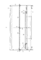
図1は、本発明の実施形態に係る擬似太陽光照射装置1の構成を模式的に示す縦断面図である。
擬似太陽光照射装置1は、複数の角柱状のフレーム2を組んで構成された格子状の枠体4を有している。この枠体4は、本実施形態では、長さが略2300mm、幅が略1300mm、高さが略1180mmの寸法に構成されている。この枠体4の長さ方向において対面する側面間に、擬似太陽光を放射する擬似太陽光照射ボックス6を渡設し、この擬似太陽光照射ボックス6の下面6Aに対向させて反射面8を配置すると共に、擬似太陽光照射ボックス6の上面6Bに対向させて太陽電池パネル等の平坦な被照射面10Aを有する被照射体10を配置して構成されており、枠体4の四方の各側面は遮光板(図示せず)で覆われている。
上記被照射体10は、枠体4の上に取り付けられた試料支持枠12に載置されることで、上記擬似太陽光照射ボックス6から所定の距離Lだけ離間した位置に被照射面10Aが配置されている。
Embodiments of the present invention will be described below with reference to the drawings.
FIG. 1 is a longitudinal sectional view schematically showing a configuration of a simulated solar
The simulated sunlight irradiating
The irradiated
図2は、上記擬似太陽光照射ボックス6の構成を示す図であり、図2(A)は断面を模式的に示す図であり、図2(B)は平面図である。
擬似太陽光照射ボックス6は、左右の両側面20A、20Bを構成する長尺の板状の一対のフレーム24と、各フレーム24に嵌め込まれて略平坦な上面6A及び下面6Bを構成する2枚のIRカットフィルタ26、27と、これらフレーム24及びIRカットフィルタを組み留めるL字金具28を有し、幅が106mm程度、高さが36mm程度の柱状に構成されており、その中に、2本の直管型のランプ(線状光源)22、23が収容されている。これらランプ22、23にはキセノンランプ等が用いられており、擬似太陽光照射時には、パルス点灯されて瞬間的に光を発する。
FIG. 2 is a diagram showing a configuration of the simulated
The simulated
また擬似太陽光照射ボックス6においては、上記一対のフレーム24が擬似太陽光照射ボックス6の長手方向の両側面20A、20Bを構成することで、これら両側面20A、20Bからの光の出射を遮蔽する遮蔽部材として機能し、また、対面する下面6A及び上面6Bが光の放射面となり、該擬似太陽光照射ボックス6から放射される光が上側に向う光と下側に向う光とに2分されることになる。放射面を構成する上記IRカットフィルタ26、27は、スペクトル分布調整用の光学フィルタであり、赤外光(熱線)をカットする特性を有する膜がコーティングされており、これらのIRカットフィルタ26、27をランプ22、23の放射光が透過することで各放射面からはスペクトル調整された擬似太陽光が放射される。
Further, in the simulated
上記IRカットフィルタ26、27には、図2(A)に矢印A及び矢印Bで示すような裏面反射が生じる。この結果、被照射体10の被照射面10Aにおいては、擬似太陽光照射ボックス6の上面6Bから出射される直射光による照度分布が次のようになる。
図3は被照射面10Aにおける照度分布を示す図であり、図4は図3のI−I線上に沿った照度分布を示す図である。なお、図3に示す点Oは、直線状に配列したランプ22、23の中央の位置(ランプ22、23の間の間隙42の位置)を示す。
一般的には、ランプ22、23の近傍が最も照度が高くなるものの、擬似太陽光照射ボックス6の各放射面においては上記のように裏面反射が生じているため、下面6AのIRカットフィルタ27にて裏面反射した光が上面6Bの放射面から幅方向に拡散放射される。この結果、図3及び図4に示すように、被照射面10Aの直射光による照度分布は、ランプ22、23からみた両側にピークPk1、Pk2を有し、そして各ピークPk1、Pk2から幅方向に離れるにつれてなだらかに照度が低下した分布となる。このため、被照射面10Aでは直接光の照射だけの場合、ランプ22、23に直交する方向において、ピークPk1、Pk2に対して照度が不足する3つの領域Ra〜Rcが発生することになる。
In the
FIG. 3 is a diagram showing an illuminance distribution on the
In general, although the illuminance is highest in the vicinity of the
擬似太陽光照射ボックス6の下側に配置された反射面8は、上記3つの領域Ra〜Rcの照度不足を補うように、擬似太陽光照射ボックス6の下面6Aの放射面からの擬似太陽光を反射して被照射面10Aを照射することで、上記直射光と反射光とにより図4の仮想線で示す如く被照射面10Aにおける照度の均一化を図るものであり、前掲図1に示すように、反射板30を傾動自在に保持する複数の反射装置32を有して構成されている。
The
図5は擬似太陽光照射装置1の擬似太陽光照射ボックス6からみて右半分を示す平面図であり、図6は擬似太陽光照射装置1の横断面を示す図である。
これらの図に示すように、上記反射板30は、上記擬似太陽光照射ボックス6に沿って略平行に延在する表面が金属の板材であり、この反射板30と、反射板30を保持する保持具31とにより上記反射装置32が構成されている。そして、枠体4の底床4A上に、複数(本実施形態では18個)の反射装置32が並設されることで、複数の反射板30が敷き詰められて設けられ、これらの反射板30により上記反射面8が形成される。
FIG. 5 is a plan view showing the right half when viewed from the simulated
As shown in these drawings, the
上記保持具31は、反射板30の傾斜角度を調節するための角度調整機構を有し、これにより、反射板30のそれぞれを、互いに独立して光の反射角度を調整することができるようになっている。このとき、前掲図1に示すように、枠体4の幅方向における両サイドに近い幾つかの保持具31の高さが順次高くなされており、両サイド側の反射板30の反射光が内側の反射板30に遮蔽されるのを防止している。
The
図7は、各反射板30からの反射光の軌跡を、ランプ22、23からみて左半分に配置された反射板30について示す図である。
この図に示すように、左半分の各反射板30の反射光は、被照射面10Aの概ね左半分に向けて照射されており、また、図示を省略した右半分の各反射板30の反射光の軌跡についても左半分の軌跡と擬似太陽光照射ボックス6を中心に対称になされており、被照射面10Aの略全面に擬似太陽光の反射光が照射される。
このとき、照度が不足する領域Ra〜Rc(図7ではRa、Rbのみ示す)ごとに、複数の反射板30からの反射光を照射する構成としている。これにより、各領域Ra〜Rcに照射する反射光の照度を多段階に調整することが可能となり、各領域Ra〜Rcにおける照度不足に応じて精度よく反射光を振り分け、被照射面10Aでの均斉度が高められる。
FIG. 7 is a diagram showing the path of reflected light from each
As shown in this figure, the reflected light of each of the
At this time, it is set as the structure which irradiates the reflected light from the some reflecting
ところで、近年の太陽電池等の大面積化に対応して被照射領域の大面積化を可能にすべく、本実施形態では、擬似太陽光照射ボックス6に2本のランプ22、23を同軸に配置することで全長を延長させた光源を構成している。このとき、前掲図5に示すように、擬似太陽光照射ボックス6においては、ランプ22、23のそれぞれの両端部に端子台40が配設されており、このため、ランプ22及びランプ23の間には、端子台40を配置するためのスペースとしての間隙42が設けられる。
このように、ランプ22及びランプ23の間に間隙42が存在すると、擬似太陽光照射ボックス6では長手方向の輝度分布において間隙42が暗くなるため、被照射面10Aの直接光による照度分布においても間隙42に対向した箇所での照度が低下する。
By the way, in order to make it possible to increase the area of the irradiated region in response to the increase in the area of solar cells and the like in recent years, in the present embodiment, the two
As described above, when the
そこで、本実施形態では、擬似太陽光照射ボックス6を枠体4に取り付ける際に、この擬似太陽光照射ボックス6の上面6Bから被照射面10Aまでの距離L(図1)を、ランプ22及びランプ23の各々から上面6Bに向けて放射された光が拡がって間隙42との対向箇所に到達し、ランプ22、23の長軸方向における照度が略一定となる程度の距離としている。
これにより、前掲図3に示すように、被照射面10Aの照度分布においては、ランプ22、23の長軸方向に沿った照度むらを防止することが可能となる。このため、ランプ22、23の長軸方向に沿った照度を反射光により補う必要がないため、被照射面10Aでの反射光による照度の補正が容易となる。
Therefore, in this embodiment, when the simulated
As a result, as shown in FIG. 3, uneven illuminance along the major axis direction of the
なお、前掲図3に示すように、本実施形態では、前掲図5及び前掲図6に示すように、長さ方向における両端側に向けて光を反射可能に構成された補助反射面50が設けられている。この補助反射面50は、例えば、擬似太陽光照射ボックス6の長さ方向における両端側での直接光の照度低下が顕著な場合に、この補助反射面50の反射角度(傾斜角度)を調整して照度低下を補うことなどに使用可能である。
As shown in FIG. 3, in this embodiment, as shown in FIG. 5 and FIG. 6, an
以上説明したように、本実施形態によれば、擬似太陽光照射ボックス6の上面6Bの放射面から被照射面10Aに向けて擬似太陽光を直接照射すると共に、上面6Bの放射面からの擬似太陽光照射において照度が他の箇所よりも不足している箇所の照度を補うように擬似太陽光照射ボックス6の下面6Aの放射面からの擬似太陽光を反射面8で反射して被照射面10Aを照射する構成としたため、直接光と反射光との両方の光が被照射面10Aに照射されるので、ランプ22、23が発する光の利用効率を高め、被照射面10Aにおいて、より高い照度を得ることができる。
これに加え、直接光の照射によって被照射面10Aに生じた照度むらを補うように反射光が照射されるため、被照射面10Aにおける照度むらを抑制することができる。
As described above, according to the present embodiment, the simulated sunlight is directly irradiated from the radiation surface of the
In addition, since the reflected light is irradiated so as to compensate for the illuminance unevenness generated on the
特に、本実施形態によれば、反射面8を、独立して反射角度が調整可能でありランプ22、23に沿って延在する複数の反射板30を並設して構成すると共に、被照射面10Aにおいて直接光照射時に照度が不足している領域Ra、Rb、Rcごとに、複数の反射板30による反射光を照射する構成としたため、各領域Ra〜Rcに照射する反射光の照度を多段階に調整することが可能となり、各領域Ra〜Rcにおける照度不足に応じて精度よく反射光を振り分け、被照射面10Aでの均斉度が高められる。
In particular, according to the present embodiment, the reflecting
また、本実施形態によれば、擬似太陽光照射ボックス6の長手方向に沿った両側面からの光の出射をフレーム24により遮蔽する構成としたため、擬似太陽光照射ボックス6から放射される光が被照射面10Aに直接向う光と反射面8に向う光とに二分され、枠体4の側面等を照射し乱反射を生じるような光が抑制されるため、被照射面10Aでの照度むらを補うようにするための反射光の設計が容易となる。
Moreover, according to this embodiment, since it was set as the structure which shields the radiation | emission of the light from the both sides along the longitudinal direction of the simulated
また、本実施形態によれば、擬似太陽光照射ボックス6の上面6Bを被照射面10Aから、ランプ22及びランプ23の各々から上面6Bに向けて放射された光が拡がって間隙42との対向箇所に到達し、ランプ22、23の長軸方向における照度が略一定となる程度の距離Lだけ離間させて配置する構成としたため、被照射面10Aの照度分布においては、ランプ22、23の長軸方向に沿った照度むらを防止することが可能となる。これにより、ランプ22、23の長軸方向に沿った照度を反射光により補う必要がないため、被照射面10Aでの反射光による照度の補正が容易となる。
Further, according to the present embodiment, the light radiated from the irradiated
なお、上述した実施の形態は、あくまでも本発明の一態様を示すものであり、本発明の範囲内で任意に変形および応用が可能であることは勿論である。 It should be noted that the above-described embodiment is merely an aspect of the present invention, and can be arbitrarily modified and applied within the scope of the present invention.
1 擬似太陽光照射装置
4 枠体
6 擬似太陽光照射ボックス
8 反射面
10 被照射体
10A 被照射面
22、23 ランプ
24 フレーム(遮蔽部材)
26、27 IRカットフィルタ
30 反射板
31 保持具
42 間隙
L 距離
DESCRIPTION OF
26, 27 IR cut
Claims (4)
前記擬似太陽光照射ボックスの上面の放射面に対向させて被照射体の被照射面を配置すると共に、前記擬似太陽光照射ボックスの下面の放射面に対向させて前記線状光源に沿って延びる反射面を設け、
前記擬似太陽光照射ボックスの上面の放射面から前記被照射面に向けて擬似太陽光を直接照射すると共に、
前記上面の放射面からの擬似太陽光照射において照度が他の箇所よりも不足している箇所の照度を補うべく当該箇所に向けて、前記擬似太陽光照射ボックスの下面の放射面からの擬似太陽光を反射して前記被照射面を照射する前記反射面を設け、
前記反射面は、前記擬似太陽光照射ボックスの直下の面が前記線状光源の長手方向に直交する方向の前記被照射面の端部を照射し、前記擬似太陽光照射ボックスの直下から遠い面が前記擬似太陽光照射ボックスの直上の前記被照射面の箇所を照射する
ことを特徴とする擬似太陽光照射装置。 Containing a linear light source, having a pseudo-sunlight irradiation box in which a radiation surface is formed on the upper surface and the lower surface, and an optical filter is provided on each radiation surface;
The irradiated surface of the irradiated object is disposed so as to face the radiation surface on the upper surface of the simulated sunlight irradiation box, and extends along the linear light source so as to face the radiation surface on the lower surface of the simulated sunlight irradiation box. Provide a reflective surface,
While directly irradiating simulated sunlight from the radiation surface of the upper surface of the simulated sunlight irradiation box toward the irradiated surface,
In order to compensate for the illuminance of the place where the illuminance is insufficient from other places in the simulated sunlight irradiation from the radiation surface of the upper surface, the simulated sun from the radiation surface of the lower surface of the simulated sunlight irradiation box toward the place Providing the reflective surface for reflecting light to irradiate the illuminated surface ;
The reflective surface irradiates an end of the irradiated surface in a direction perpendicular to the longitudinal direction of the linear light source, and the surface immediately below the simulated sunlight irradiation box is a surface far from directly below the simulated sunlight irradiation box. Irradiates a portion of the irradiated surface directly above the simulated sunlight irradiation box .
前記反射面を、独立して反射角度が調整可能であり前記線状光源の長手方向に沿って延在する複数の反射板を並設して構成すると共に、前記上面の放射面からの擬似太陽光照射において照度が他の箇所よりも不足している箇所に対して複数の前記反射板による反射光を照射する
ことを特徴とする擬似太陽光照射装置。 In the simulated solar light irradiation device according to claim 1,
The reflection surface is configured by arranging a plurality of reflection plates, the reflection angle of which can be adjusted independently, and extending along the longitudinal direction of the linear light source , and the pseudo sun from the radiation surface of the upper surface. The pseudo-sunlight irradiating apparatus characterized by irradiating the reflected light from the plurality of the reflecting plates to a place where the illuminance is insufficient compared with other places in the light irradiation.
前記線状光源の長手方向に沿った前記擬似太陽光照射ボックスの長手方向に沿った両側面からの光の出射を遮蔽する遮蔽部材を備えた
ことを特徴とする擬似太陽光照射装置。 In the pseudo-sunlight irradiation device according to claim 1 or 2,
A pseudo-sunlight irradiation apparatus, comprising: a shielding member that shields light emission from both side surfaces along the longitudinal direction of the pseudo-sunlight irradiation box along the longitudinal direction of the linear light source .
前記擬似太陽光照射ボックスの中に複数の前記線状光源を各々の間に所定の間隙を設けて略同軸に配置し、
前記擬似太陽光照射ボックスの上面の放射面からの擬似太陽光を前記被照射面に照射した際に、当該擬似太陽光の照射により複数の前記線状光源の長軸方向において照度が略一定になる距離だけ前記擬似太陽光照射ボックスを前記被照射面から離間した位置に配置した
ことを特徴とする擬似太陽光照射装置。 In the pseudo-sunlight irradiation device according to any one of claims 1 to 3,
In the pseudo-sunlight irradiation box, a plurality of the linear light sources are arranged substantially coaxially with a predetermined gap between them,
When the irradiated surface is irradiated with simulated sunlight from the radiation surface on the upper surface of the simulated sunlight irradiation box, the illumination is substantially constant in the major axis direction of the plurality of linear light sources by irradiation of the simulated sunlight. The simulated sunlight irradiation device is characterized in that the simulated sunlight irradiation box is disposed at a position separated from the irradiated surface by a distance of
Priority Applications (1)
| Application Number | Priority Date | Filing Date | Title |
|---|---|---|---|
| JP2007324304A JP4973479B2 (en) | 2007-12-17 | 2007-12-17 | Simulated solar irradiation device |
Applications Claiming Priority (1)
| Application Number | Priority Date | Filing Date | Title |
|---|---|---|---|
| JP2007324304A JP4973479B2 (en) | 2007-12-17 | 2007-12-17 | Simulated solar irradiation device |
Publications (2)
| Publication Number | Publication Date |
|---|---|
| JP2009145254A JP2009145254A (en) | 2009-07-02 |
| JP4973479B2 true JP4973479B2 (en) | 2012-07-11 |
Family
ID=40916002
Family Applications (1)
| Application Number | Title | Priority Date | Filing Date |
|---|---|---|---|
| JP2007324304A Expired - Fee Related JP4973479B2 (en) | 2007-12-17 | 2007-12-17 | Simulated solar irradiation device |
Country Status (1)
| Country | Link |
|---|---|
| JP (1) | JP4973479B2 (en) |
Families Citing this family (4)
| Publication number | Priority date | Publication date | Assignee | Title |
|---|---|---|---|---|
| JP5251714B2 (en) * | 2009-05-08 | 2013-07-31 | 岩崎電気株式会社 | Simulated solar irradiation device |
| JP5049375B2 (en) | 2010-09-29 | 2012-10-17 | シャープ株式会社 | Simulated solar irradiation device |
| JP5274528B2 (en) | 2010-10-08 | 2013-08-28 | シャープ株式会社 | Pseudo-sunlight irradiation device and solar panel inspection device |
| JP5708128B2 (en) * | 2011-03-28 | 2015-04-30 | ウシオ電機株式会社 | Light irradiation device |
Family Cites Families (12)
| Publication number | Priority date | Publication date | Assignee | Title |
|---|---|---|---|---|
| US3630627A (en) * | 1970-02-27 | 1971-12-28 | Nasa | Solar cell assembly test method |
| JPS60145472U (en) * | 1984-03-07 | 1985-09-27 | 菊水化学工業株式会社 | Simulated solar experimental device |
| JPS6466542A (en) * | 1987-09-08 | 1989-03-13 | Toyota Central Res & Dev | Accelerated weathering test method and apparatus |
| JP3500352B2 (en) * | 2000-08-07 | 2004-02-23 | 日清紡績株式会社 | Solar simulator |
| JP3388283B2 (en) * | 2000-12-26 | 2003-03-17 | スガ試験機株式会社 | Weathering test equipment |
| JP3460149B2 (en) * | 2001-04-02 | 2003-10-27 | 日清紡績株式会社 | Simulated sunlight irradiation device |
| JP2003028785A (en) * | 2001-07-13 | 2003-01-29 | Nisshinbo Ind Inc | Pseudo sunlight irradiation device |
| JP2003078717A (en) * | 2001-08-31 | 2003-03-14 | Brother Ind Ltd | Imaging apparatus for irregular object, illumination device for imaging and imaging method |
| EP1668343A1 (en) * | 2003-09-24 | 2006-06-14 | Q-Panel Lab Products Corporation | Method and apparatus for determining the resistance of materials to light and corrosives |
| JP2006047798A (en) * | 2004-08-06 | 2006-02-16 | Sanyo Electric Co Ltd | Liquid crystal display device |
| JP5236858B2 (en) * | 2005-02-01 | 2013-07-17 | 日清紡ホールディングス株式会社 | Measuring method of output characteristics of solar cell. |
| JP3132621U (en) * | 2007-04-05 | 2007-06-14 | スガ試験機株式会社 | Irradiance meter |
-
2007
- 2007-12-17 JP JP2007324304A patent/JP4973479B2/en not_active Expired - Fee Related
Also Published As
| Publication number | Publication date |
|---|---|
| JP2009145254A (en) | 2009-07-02 |
Similar Documents
| Publication | Publication Date | Title |
|---|---|---|
| US8869419B2 (en) | Efficient irradiation system using curved reflective surfaces | |
| EP2628997A1 (en) | Light irradiation device, simulated sunlight light irradiation device, and inspection device for solar cell panel | |
| JP5612380B2 (en) | LED lighting fixtures | |
| TW201219690A (en) | Solar simulator and solar cell examination apparatus | |
| US20190124854A1 (en) | Plant growth lighting systems | |
| JP5497481B2 (en) | Simulated solar irradiation device | |
| JP2014053098A (en) | Solar simulator | |
| JP4973479B2 (en) | Simulated solar irradiation device | |
| JP2003028785A (en) | Pseudo sunlight irradiation device | |
| JP2011181298A5 (en) | ||
| JP5251075B2 (en) | LED light source device | |
| JP5493428B2 (en) | Weather resistance test equipment | |
| JP5092875B2 (en) | Simulated solar irradiation device | |
| JP6171483B2 (en) | Irradiation device | |
| JP5251714B2 (en) | Simulated solar irradiation device | |
| JP5178610B2 (en) | Light irradiation device | |
| US20120287599A1 (en) | Light irradiation apparatus, pseudo-sunlight irradiation apparatus and solar panel inspection apparatus | |
| US20120287598A1 (en) | Pseudo-sunlight irradiation apparatus and solar panel inspection apparatus | |
| JP2010171132A (en) | Pseudo sunlight irradiation device | |
| JP5605403B2 (en) | Simulated solar irradiation device | |
| JP3180295U (en) | Lighting device | |
| JP2015184270A (en) | Pseudo sunlight irradiation device | |
| JP2011003475A (en) | Pseudo-sunlight irradiating device | |
| US20150076367A1 (en) | Efficient radiating system using curved reflective surfaces | |
| US20150076368A1 (en) | Efficient irradiation system using curved reflective surfaces |
Legal Events
| Date | Code | Title | Description |
|---|---|---|---|
| A625 | Written request for application examination (by other person) |
Free format text: JAPANESE INTERMEDIATE CODE: A625 Effective date: 20100608 |
|
| A977 | Report on retrieval |
Free format text: JAPANESE INTERMEDIATE CODE: A971007 Effective date: 20111220 |
|
| A131 | Notification of reasons for refusal |
Free format text: JAPANESE INTERMEDIATE CODE: A131 Effective date: 20111227 |
|
| A521 | Request for written amendment filed |
Free format text: JAPANESE INTERMEDIATE CODE: A523 Effective date: 20120223 |
|
| RD02 | Notification of acceptance of power of attorney |
Free format text: JAPANESE INTERMEDIATE CODE: A7422 Effective date: 20120223 |
|
| TRDD | Decision of grant or rejection written | ||
| A01 | Written decision to grant a patent or to grant a registration (utility model) |
Free format text: JAPANESE INTERMEDIATE CODE: A01 Effective date: 20120313 |
|
| A01 | Written decision to grant a patent or to grant a registration (utility model) |
Free format text: JAPANESE INTERMEDIATE CODE: A01 |
|
| A61 | First payment of annual fees (during grant procedure) |
Free format text: JAPANESE INTERMEDIATE CODE: A61 Effective date: 20120326 |
|
| R150 | Certificate of patent or registration of utility model |
Ref document number: 4973479 Country of ref document: JP Free format text: JAPANESE INTERMEDIATE CODE: R150 Free format text: JAPANESE INTERMEDIATE CODE: R150 |
|
| FPAY | Renewal fee payment (event date is renewal date of database) |
Free format text: PAYMENT UNTIL: 20150420 Year of fee payment: 3 |
|
| S531 | Written request for registration of change of domicile |
Free format text: JAPANESE INTERMEDIATE CODE: R313531 |
|
| R350 | Written notification of registration of transfer |
Free format text: JAPANESE INTERMEDIATE CODE: R350 |
|
| LAPS | Cancellation because of no payment of annual fees |