JP4969514B2 - Magnetic disk device, control method thereof, and manufacturing method thereof - Google Patents
Magnetic disk device, control method thereof, and manufacturing method thereof Download PDFInfo
- Publication number
- JP4969514B2 JP4969514B2 JP2008133561A JP2008133561A JP4969514B2 JP 4969514 B2 JP4969514 B2 JP 4969514B2 JP 2008133561 A JP2008133561 A JP 2008133561A JP 2008133561 A JP2008133561 A JP 2008133561A JP 4969514 B2 JP4969514 B2 JP 4969514B2
- Authority
- JP
- Japan
- Prior art keywords
- track
- magnetic disk
- interval
- magnetic head
- disk device
- Prior art date
- Legal status (The legal status is an assumption and is not a legal conclusion. Google has not performed a legal analysis and makes no representation as to the accuracy of the status listed.)
- Expired - Fee Related
Links
Images


Classifications
-
- G—PHYSICS
- G11—INFORMATION STORAGE
- G11B—INFORMATION STORAGE BASED ON RELATIVE MOVEMENT BETWEEN RECORD CARRIER AND TRANSDUCER
- G11B5/00—Recording by magnetisation or demagnetisation of a record carrier; Reproducing by magnetic means; Record carriers therefor
- G11B5/02—Recording, reproducing, or erasing methods; Read, write or erase circuits therefor
- G11B5/09—Digital recording
-
- G—PHYSICS
- G11—INFORMATION STORAGE
- G11B—INFORMATION STORAGE BASED ON RELATIVE MOVEMENT BETWEEN RECORD CARRIER AND TRANSDUCER
- G11B19/00—Driving, starting, stopping record carriers not specifically of filamentary or web form, or of supports therefor; Control thereof; Control of operating function ; Driving both disc and head
- G11B19/02—Control of operating function, e.g. switching from recording to reproducing
- G11B19/04—Arrangements for preventing, inhibiting, or warning against double recording on the same blank or against other recording or reproducing malfunctions
- G11B19/041—Detection or prevention of read or write errors
- G11B19/045—Detection or prevention of read or write errors by detecting mistracking
-
- G—PHYSICS
- G11—INFORMATION STORAGE
- G11B—INFORMATION STORAGE BASED ON RELATIVE MOVEMENT BETWEEN RECORD CARRIER AND TRANSDUCER
- G11B2220/00—Record carriers by type
- G11B2220/20—Disc-shaped record carriers
- G11B2220/25—Disc-shaped record carriers characterised in that the disc is based on a specific recording technology
- G11B2220/2508—Magnetic discs
- G11B2220/2516—Hard disks
-
- Y—GENERAL TAGGING OF NEW TECHNOLOGICAL DEVELOPMENTS; GENERAL TAGGING OF CROSS-SECTIONAL TECHNOLOGIES SPANNING OVER SEVERAL SECTIONS OF THE IPC; TECHNICAL SUBJECTS COVERED BY FORMER USPC CROSS-REFERENCE ART COLLECTIONS [XRACs] AND DIGESTS
- Y10—TECHNICAL SUBJECTS COVERED BY FORMER USPC
- Y10T—TECHNICAL SUBJECTS COVERED BY FORMER US CLASSIFICATION
- Y10T29/00—Metal working
- Y10T29/49—Method of mechanical manufacture
- Y10T29/49002—Electrical device making
- Y10T29/4902—Electromagnet, transformer or inductor
- Y10T29/49021—Magnetic recording reproducing transducer [e.g., tape head, core, etc.]
- Y10T29/49025—Making disc drive
Description
本発明は、磁気ディスク装置、その制御方法、及びその製造方法に関し、特に磁気ヘッドによるデータの書き込みの可否を判定する技術に関する。 The present invention relates to a magnetic disk device, a control method thereof, and a manufacturing method thereof, and more particularly to a technique for determining whether data can be written by a magnetic head.
ハードディスク等の磁気ディスク装置では、磁気ディスクに複数のトラックが形成されており、これらの中から決定される目標トラックに磁気ヘッドが位置決めされて、データの書き込みが行われる。この際、磁気ヘッドの位置誤差が所定の許容範囲内にあるか否かによって、データの書き込みの可否が判定される。
ところで、磁気ディスクにトラックを形成する方法の一つとして、磁気ディスク装置が有する位置決め機構を利用して、磁気ヘッドによりサーボデータを書き込む、いわゆるセルフサーボライト方式が知られている。こうして形成される複数のトラックでは、磁気ヘッドの浮上特性などの要因によって、磁気ディスクの半径位置に応じてトラック間隔が異なることがある。 By the way, as one method for forming a track on a magnetic disk, a so-called self-servo write system is known in which servo data is written by a magnetic head using a positioning mechanism of a magnetic disk device. In a plurality of tracks formed in this way, the track interval may differ depending on the radial position of the magnetic disk due to factors such as the flying characteristics of the magnetic head.
このようにトラック間隔が異なる場合、データの書き込み時に実際に許容される磁気ヘッドの位置誤差もこれに応じて変化するはずであるが、従来の磁気ディスク装置では書き込みの可否判定に一律の許容範囲を適用しているため、適用される許容範囲が実際の許容範囲と乖離して、書き込み性能が劣化してしまう虞があった。 When the track spacing is different in this way, the magnetic head position error that is actually allowed at the time of data writing should also change accordingly, but in conventional magnetic disk devices, a uniform allowable range for determining whether or not writing is possible. Therefore, there is a possibility that the permissible range to be applied deviates from the actual permissible range and the writing performance is deteriorated.
本発明は、上記実情に鑑みて為されたものであり、データの書き込みの可否を判定する際に適用される、磁気ヘッドの位置誤差の許容範囲を適正化することが可能な、磁気ディスク装置、その制御方法、及びその製造方法を提供することを主な目的とする。 The present invention has been made in view of the above circumstances, and is a magnetic disk device capable of optimizing the allowable range of the position error of the magnetic head, which is applied when determining whether data can be written. It is a main object to provide a control method and a manufacturing method thereof.
上記課題を解決するため、本発明の磁気ディスク装置は、複数のトラックが形成された磁気ディスクと、前記複数のトラックの中から決定される目標トラックに位置決めされ、データの書き込み及び読み出しを行う磁気ヘッドと、を備える磁気ディスク装置であって、前記磁気ヘッドの位置誤差の許容範囲を前記目標トラックに応じて決定する決定手段と、前記磁気ヘッドが読み出したデータから算出される前記目標トラックに対する前記磁気ヘッドの位置誤差、及び前記許容範囲に基づいて、前記磁気ヘッドによるデータの書き込みの可否を判定する判定手段と、を備える。 In order to solve the above problems, a magnetic disk apparatus according to the present invention includes a magnetic disk on which a plurality of tracks are formed, and a magnetic disk that is positioned on a target track determined from the plurality of tracks and performs data writing and reading. A magnetic disk apparatus comprising: a head; a determination unit that determines an allowable range of a position error of the magnetic head according to the target track; and the target track calculated from data read by the magnetic head. Determination means for determining whether or not data can be written by the magnetic head based on the positional error of the magnetic head and the allowable range.
また、本発明の一態様において、前記決定手段は、予め評価された前記複数のトラックの各トラック間隔に基づき、前記目標トラックでのトラック間隔を求め、当該トラック間隔に応じて前記許容範囲を決定する。 In the aspect of the invention, the determining unit obtains a track interval at the target track based on each track interval of the plurality of tracks evaluated in advance, and determines the allowable range according to the track interval. To do.
この態様において、前記複数のトラックの各トラック間隔を予め評価することで作成された、前記各トラックとトラック間隔との関係を表すテーブルを保持する保持手段を更に備え、前記決定手段は、前記テーブルから前記目標トラックでのトラック間隔を読み出すようにすることができる。 In this aspect, the apparatus further comprises holding means for holding a table representing a relationship between each track and the track interval, which is created by evaluating each track interval of the plurality of tracks in advance. The track interval at the target track can be read out from.
また、この態様において、前記決定手段は、前記複数のトラックの各トラック間隔を予め評価することで作成された、前記各トラックとトラック間隔との関係を表す式から、前記目標トラックでのトラック間隔を求めるようにすることができる。 Further, in this aspect, the determining means calculates the track interval at the target track from an expression representing the relationship between each track and the track interval, which is created by evaluating each track interval of the plurality of tracks in advance. Can be requested.
また、本発明の一態様において、前記決定手段は、予め評価された前記複数のトラックの前記磁気ディスクの半径位置に応じたトラック間隔に基づき、前記目標トラックでのトラック間隔を求め、当該トラック間隔に応じて前記許容範囲を決定する。 In one aspect of the present invention, the determining unit obtains a track interval at the target track based on a track interval corresponding to a radial position of the magnetic disk of the plurality of tracks evaluated in advance, and determines the track interval. The allowable range is determined according to the above.
また、本発明の磁気ディスク装置の制御方法は、複数のトラックが形成された磁気ディスクと、前記複数のトラックの中から決定される目標トラックに位置決めされ、データの書き込み及び読み出しを行う磁気ヘッドと、を備える磁気ディスク装置の制御方法であって、前記磁気ヘッドの位置誤差の許容範囲を前記目標トラックに応じて決定し、前記磁気ヘッドが読み出したデータから算出される前記目標トラックに対する前記磁気ヘッドの位置誤差、及び前記許容範囲に基づいて、前記磁気ヘッドによるデータの書き込みの可否を判定する。 According to another aspect of the present invention, there is provided a method for controlling a magnetic disk device comprising: a magnetic disk having a plurality of tracks; a magnetic head positioned on a target track determined from the plurality of tracks; The magnetic head for a target track calculated from data read by the magnetic head, wherein an allowable range of a position error of the magnetic head is determined according to the target track Whether or not data can be written by the magnetic head is determined based on the position error and the allowable range.
また、本発明の磁気ディスク装置の製造方法は、複数のトラックが形成された磁気ディスクと、前記複数のトラックの中から決定される目標トラックに位置決めされ、データの書き込み及び読み出しを行う磁気ヘッドと、を備える磁気ディスク装置の製造方法であって、前記複数のトラックの各トラック間隔を評価し、前記各トラックとトラック間隔との関係を表すデータを、前記磁気ディスク装置の記憶部に格納する。 The method of manufacturing a magnetic disk apparatus according to the present invention includes a magnetic disk on which a plurality of tracks are formed, a magnetic head that is positioned on a target track determined from the plurality of tracks, and that writes and reads data. The track interval of the plurality of tracks is evaluated, and data representing the relationship between each track and the track interval is stored in the storage unit of the magnetic disk device.
本発明によれば、磁気ヘッドの位置誤差の許容範囲を目標トラックに応じて決定しているので、許容範囲の適正化を図ることが可能である。 According to the present invention, since the allowable range of the position error of the magnetic head is determined according to the target track, it is possible to optimize the allowable range.
本発明の実施形態について、図面を参照しながら説明する。 Embodiments of the present invention will be described with reference to the drawings.
図1は、本発明の一実施形態に係る磁気ディスク装置1の構成例である。磁気ディスク装置1の筐体9には、磁気ディスク2及びヘッドアッセンブリ6が収納されている。磁気ディスク2は、筐体9の底部に設けられたスピンドルモータ3に取り付けられている。
FIG. 1 is a configuration example of a
磁気ディスク2には、同心円状に配列する複数のトラック21が形成されている。各トラック21には、周方向に沿って所定の周期で配列するサーボデータ領域21sと、これらの間に位置するユーザデータ領域21uとが形成されている。サーボデータ領域21sには、アドレスデータ及びバースト信号を含むサーボデータが記録されている。ユーザデータ領域21uには、ユーザデータが記録される。
A plurality of
ヘッドアッセンブリ6は、磁気ディスク2の隣で旋回可能に支承されている。ヘッドアッセンブリ6の先端部には、磁気ヘッド4が支持されている。他方、ヘッドアッセンブリ6の後端部には、ボイスコイルモータ7が設けられている。ボイスコイルモータ7は、ヘッドアッセンブリ6を旋回駆動することで、磁気ヘッド4を磁気ディスク2上で略半径方向に移動させる。
The
また、磁気ディスク装置1は、筐体9外の基板に、主制御回路10、リードライトチャネル(R/Wチャネル)13及びモータドライバ17を有している。この主制御回路10は、マイクロプロセッシングユニット(MPU)と、ハードディスクコントローラ(HDC)と、メモリとを含んでいる。
The
主制御回路10は、磁気ディスク2に記録すべきユーザデータを外部ホストから受信すると、このユーザデータをR/Wチャネル13へ出力する。R/Wチャネル13は、このユーザデータを変調して、ヘッドアンプ14へ出力する。ヘッドアンプ14は、この変調されたユーザデータを記録信号に変換して、磁気ヘッド4へ出力する。磁気ヘッド4は、この記録信号に応じた磁界を磁気ディスク2に印加して、ユーザデータを書き込む。
When the
他方、磁気ヘッド4は、磁気ディスク2から漏れ出る磁界から再生信号を読み出し、この再生信号をヘッドアンプ14へ出力する。ヘッドアンプ14は、この再生信号を増幅して、R/Wチャネル13へ出力する。R/Wチャネル13は、この増幅された再生信号をデジタルデータに変換し、復調して、主制御回路10へ出力する。主制御回路10は、この復調されたユーザデータを外部ホストへ送信する。
On the other hand, the
また、R/Wチャネル13は、再生信号から所定のサンプリング周期でサーボデータを抽出して、主制御回路10へ出力する。
The R /
更に、主制御回路10は、メモリに格納されたプログラムを読み出し、実行することで、磁気ヘッド4の位置制御など、種々の制御を実行する。
Furthermore, the
磁気ヘッド4の位置制御において、主制御回路10は、磁気ヘッド4が読み出したサーボデータから磁気ヘッド4の現在位置を特定するとともに、磁気ヘッド4を目標トラック上に位置させるための制御信号を生成し、モータドライバ17を介してボイスコイルモータ7へ出力する。具体的には、主制御回路10は、磁気ヘッド4の位置制御としてシーク制御およびフォロイング制御を実行する。
In the position control of the
このシーク制御において、主制御回路10は、外部ホストからの記録命令または再生命令に基づいて複数のトラック21の中から目標トラックを取得するとともに、磁気ヘッド4が読み出したサーボデータにより磁気ヘッド4の現在位置を特定し、目標トラックに向けて磁気ヘッド4を移動させる。その後、主制御回路10はフォロイング制御に移行する。
In this seek control, the
このフォロイング制御において、主制御回路10は、磁気ヘッド4が読み出したサーボデータに含まれるバースト信号から、目標トラックに対する磁気ヘッド4の位置誤差を表す誤差信号(PES:Position Error Signal)を算出し、目標トラックに磁気ヘッド4を位置決めする。磁気ヘッド4によるデータの書き込み及び読み出しは、このフォロイング制御中に行われる。
In this following control, the
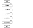
以下、本発明の一実施形態に係る磁気ディスク装置の制御方法について、図2のフローチャートを用いて説明する。 Hereinafter, a method for controlling a magnetic disk device according to an embodiment of the present invention will be described with reference to the flowchart of FIG.
まず、主制御回路10は、外部ホストから記録要求を受けると(S11)、磁気ヘッド4の目標位置を取得する(S12)。具体的には、外部ホストからの記録要求には、データの記録場所を通し番号で特定するLBA(Logical Block Address)パラメータが含まれており、主制御回路10は、このLBAパラメータを、データの記録場所をトラック番号やセクタ番号等で特定するCHSパラメータに変換することで、磁気ヘッド4の目標位置を取得する。従って、この目標位置に含まれるトラック番号は、目標トラックを表す。また、主制御回路10は、この動作に伴って上記シーク制御を実行する。
First, when receiving a recording request from an external host (S11), the
S13において、主制御回路10は、目標トラックでのトラック間隔(トラックピッチ)を取得する(決定手段としての機能の一部)。具体的には、主制御回路10は、保持手段としてのメモリに保持された、各トラックとトラック間隔との関係を表すテーブルを参照し、目標トラックに対応するトラック間隔を読み出す。
In S13, the
図3Aに、テーブルの内容例を示す。このテーブルは、後述するように、磁気ディスク2に形成された複数のトラック21の各トラック間隔を予め評価することで作成される。このテーブルでは、所定数のトラックを含むグループ毎にトラック間隔が対応付けられている。これらのグループは、トラック番号が連続する所定数のトラック毎に分けられている。ここで、トラック番号は、磁気ディスク2の半径位置に対応することから、このテーブルは、磁気ディスク2の半径位置に応じたトラック間隔を表しているということができる。なお、この例に限らず、1つのトラック毎にトラック間隔が対応付けられていてもよい。
FIG. 3A shows an example of the contents of the table. As will be described later, this table is created by evaluating each track interval of the plurality of
または、主制御回路10は、各トラックとトラック間隔との関係を表す式に基づいて、目標トラックでのトラック間隔を求めるようにしてもよい。図3Bに、式の内容例を示す。この式も、後述するように、磁気ディスク2に形成された複数のトラック21の各トラック間隔を予め評価することで作成される。この式では、トラック番号に応じたトラック間隔が関数で表されている。この式も、磁気ディスク2の半径位置に応じたトラック間隔を表しているということができる。
Alternatively, the
図2のフローチャートの説明に戻り、S14において、主制御回路10は、磁気ヘッド4の位置誤差を表す誤差信号PESの許容範囲を、目標トラックでのトラック間隔に応じて決定する(決定手段としての機能の一部)。この許容範囲は、後述するように、磁気ヘッド4がデータを書き込む際に、磁気ヘッド4の位置誤差がどの程度まで許容されるかを表す。具体的には、主制御回路10は、許容範囲の閾値を計算によって求める。この許容範囲の閾値は、書き込み禁止閾値(Write Inhibit Criteria)と呼ばれる。
Returning to the description of the flowchart of FIG. 2, in S14, the
許容範囲の閾値は、例えば下記数式1のように求めることができる。この数式1において、WICは求める許容範囲の閾値を表し、TPAは目標トラックでのトラック間隔を表す。また、TPRは基準となるトラック間隔を表し、WICRは基準となるトラック間隔での許容範囲の閾値を表す。
The threshold value of the allowable range can be obtained, for example, as shown in

S15において、主制御回路10は、算出した許容範囲を、データを書き込む際の誤差信号PESの許容範囲として設定する。これにより、主制御回路10は、シーク制御からフォロイング制御に移行し、磁気ヘッド4によりデータを書き込む際に、誤差信号PESが許容範囲の閾値(書き込み禁止閾値)を超えるか否かによって、書き込みの可否を判定する(判定手段としての機能)。
In S15, the
なお、以上の例に限らず、例えば、予め評価された複数のトラック21の各トラック間隔から予め決定される各トラックの許容範囲に基づいて、目標トラックに応じた許容範囲が決定されるようにしてもよい。すなわち、各トラックと許容範囲との関係を表すテーブル等を予め作成しておき、このテーブル等に基づいて目標トラックに応じた許容範囲が決定されるようにしてもよい。
Note that the present invention is not limited to the above example. For example, the allowable range corresponding to the target track is determined based on the allowable range of each track determined in advance from the track intervals of the plurality of
以下、本発明の一実施形態に係る磁気ディスク装置の製造方法について、図4のフローチャートを用いて説明する。このフローチャートは、磁気ディスク2に複数のトラック21が形成された後の製造過程の一部を表す。
Hereinafter, a method of manufacturing a magnetic disk device according to an embodiment of the present invention will be described with reference to the flowchart of FIG. This flowchart represents a part of the manufacturing process after the plurality of
S51では、磁気ディスク2に形成された複数のトラック21の各トラック間隔が評価される。トラック間隔の評価は、磁気ディスク装置1が有する位置決め機構を利用して行われる。具体的には、外部装置によって、ボイスコイルモータ7が制御されるとともに、磁気ヘッド4に読み出されたサーボデータが取得される。この操作は、主制御回路10によって行われるようにしてもよい。そして、こうして取得されたサーボデータに基づいて、トラック間隔が評価される。具体的には、例えば次のような方法でトラック間隔を評価することができる。
In S51, the track intervals of the plurality of
図5Aないし図5Cに、磁気ディスク2に形成されるトラック21の例を示す。これらの図では、サーボデータに含まれるバースト信号A〜Dの部分を拡大して示している。各トラック21は、これらバースト信号A〜Dによって定められる。具体的には、バースト信号Aとバースト信号Bの記録幅方向の中間が、トラック21の中心21cとされる。
5A to 5C show examples of the
ここで、バースト信号Aとバースト信号B、またバースト信号Cとバースト信号Dは、図5Bに示されるように記録幅方向に一部が重なって記録されたり、図5Cに示されるように記録幅方向に離れて記録されることがある。このため、図5Aないし図5Cのそれぞれの場合で、トラック21の中心21cの間隔(トラック間隔)が異なることになる。
Here, the burst signal A and the burst signal B, and the burst signal C and the burst signal D are partially overlapped in the recording width direction as shown in FIG. 5B, or the recording width as shown in FIG. 5C. May be recorded away in the direction. For this reason, in each case of FIG. 5A thru | or FIG. 5C, the space | interval (track space | interval) of the
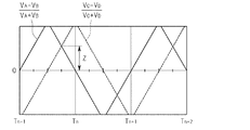
図6Aないし図6Cに、トラック21から読み出されるバースト信号の例を示す。これらの図は、上記図5Aないし図5Cにそれぞれ対応する。これらの図において、横軸はトラック21の幅方向の位置を表し、Tは各トラック21の中心21cを表す。縦軸は、各位置で読み出されるバースト信号A〜Dの振幅VA〜VDから計算される振幅比(VA−VB)/(VA+VB)及び振幅比(VC−VD)/(VC+VD)を表す。
6A to 6C show examples of burst signals read from the
ここで、トラック21の中心21cからトラック間隔の1/4だけ離れた位置では、振幅比(VA−VB)/(VA+VB)及び振幅比(VC−VD)/(VC+VD)が同じになる(以下、このときの振幅比を「振幅比Z」という)。そして、この振幅比Zは、トラック間隔に応じて変化する。すなわち、トラック間隔が狭いほど振幅比Zが小さくなり、他方、トラック間隔が広いほど振幅比Zが大きくなる。従って、このことを利用して、振幅比Zからトラック間隔を求めることができる。
Here, at a position away from the
そこで、外部装置は、再生素子41に読み出されるバースト信号A〜Dの振幅比(VA−VB)/(VA+VB)及び振幅比(VC−VD)/(VC+VD)が同じ大きさとなるようにボイスコイルモータ7を制御することで、トラック21の中心21cからトラック幅の1/4だけ離れた位置に再生素子41を位置決めし(図5を参照)、このときの振幅比Zを取得する。そして、こうして取得された振幅比Zからトラック間隔が求められる。
Therefore, the external device uses the amplitude ratio (V A −V B ) / (V A + V B ) and the amplitude ratio (V C −V D ) / (V C + V D ) of the burst signals A to D read to the reproduction element 41. ) Is controlled so as to have the same size, the reproducing
こうしたトラック間隔を求めるための操作は、例えば、磁気ディスク2に形成された複数のトラック21のうち、所定数おきのトラックに対して行うことができる。すなわち、複数のトラック21を、トラック番号が連続する所定数のトラック毎の複数のグループに分け、各グループの代表のトラックに対して上記操作が行われる。図7に、このようにして得られる評価結果の例を示す。なお、これに限らず、磁気ディスク2に形成された全てのトラック21についてトラック間隔を求めるようにしてもよい。
Such an operation for obtaining the track interval can be performed on every predetermined number of tracks among the plurality of
図4のフローチャートの説明に戻り、S52では、上記評価結果に基づいて、各トラック21とトラック間隔との関係を表すデータが作成される。具体的には、各トラック21とトラック間隔との関係を表すデータとして、上記図3Aに示されたテーブルが作成される。ここでは、各グループの代表のトラックについて求めたトラック間隔が、各グループに属するトラック21のトラック間隔として対応付けられて、テーブルが作成される。
Returning to the description of the flowchart of FIG. 4, in S52, data representing the relationship between each
または、各トラック21とトラック間隔との関係を表すデータとして、上記図3Bに示された式を含むデータ(例えばプログラム)が作成されてもよい。この式は、例えば上記図7に示される評価結果を関数で近似することで作成される。
Alternatively, data (for example, a program) including the expression shown in FIG. 3B may be created as data representing the relationship between each
なお、これらの例では、評価結果をそのまま用いること、又は加工することでテーブル等のデータを作成しているが、データの作成方法はこれらに限られない。例えば、磁気ディスクの半径位置に応じたトラック間隔の代表的な特性を表すデータを予め複数作成しておき、この中から評価結果に最も近いものを選択的に用いるようにしてもよい。 In these examples, data such as a table is created by using the evaluation result as it is or processing it, but the data creation method is not limited to this. For example, a plurality of data representing typical characteristics of the track interval according to the radial position of the magnetic disk may be created in advance, and the data closest to the evaluation result may be selectively used.
S53では、こうして作成されたデータが、磁気ディスク装置1の主制御回路10のメモリに格納される。なお、データが磁気ディスク2に記録されてもよい。このように格納されたデータは、上述したように、磁気ディスク装置1において、誤差信号PESの許容範囲を目標トラックに応じて決定する際に使用される。
In S53, the data thus created is stored in the memory of the
以上、本発明の実施形態について説明したが、本発明は上記実施形態に限定されるものではなく、種々の変形実施が当業者にとって可能であるのはもちろんである。 Although the embodiments of the present invention have been described above, the present invention is not limited to the above-described embodiments, and various modifications can be made by those skilled in the art.
1 磁気ディスク装置、2 磁気ディスク、3 スピンドルモータ、4 磁気ヘッド、6 ヘッドアッセンブリ、7 ボイスコイルモータ、9 筐体、10 主制御回路、13 R/Wチャネル、14 ヘッドアンプ、17 モータドライバ、21 トラック、21s サーボデータ領域、21u ユーザデータ領域、21c トラック中心、41 再生素子。
DESCRIPTION OF
Claims (7)
前記磁気ヘッドの位置誤差の許容範囲を前記目標トラックのトラック間隔に応じて決定する決定手段と、
前記磁気ヘッドが読み出したデータから算出される前記目標トラックに対する前記磁気ヘッドの位置誤差、及び前記トラック間隔に応じた前記許容範囲に基づいて、前記磁気ヘッドによるデータの書き込みの可否を判定する判定手段と、
を備える磁気ディスク装置。 A magnetic disk having a plurality of tracks formed on at least one surface and a target track determined from among the plurality of tracks formed on one surface of the magnetic disk, and writing and reading data A magnetic disk device comprising a magnetic head,
Determining means for determining an allowable range of a position error of the magnetic head according to a track interval of the target track;
Determination means for determining whether or not data can be written by the magnetic head based on a positional error of the magnetic head with respect to the target track calculated from data read by the magnetic head and the allowable range corresponding to the track interval. When,
A magnetic disk device comprising:
請求項1に記載の磁気ディスク装置。 The determining means obtains a track interval at the target track based on each track interval of the plurality of tracks evaluated in advance, and determines the allowable range according to the track interval.
The magnetic disk device according to claim 1.
前記決定手段は、前記テーブルから前記目標トラックでのトラック間隔を読み出す、
請求項2に記載の磁気ディスク装置。 Further comprising holding means for holding a table representing a relationship between each track and the track interval created by evaluating each track interval of the plurality of tracks in advance;
The determination means reads a track interval at the target track from the table.
The magnetic disk device according to claim 2.
請求項2に記載の磁気ディスク装置。 The determining means obtains the track interval at the target track from an expression representing the relationship between each track and the track interval created by evaluating each track interval of the plurality of tracks in advance.
The magnetic disk device according to claim 2.
請求項1に記載の磁気ディスク装置。 The determining means obtains a track interval at the target track based on a track interval corresponding to a radial position of the magnetic disk of the plurality of tracks evaluated in advance, and determines the allowable range according to the track interval. ,
The magnetic disk device according to claim 1.
前記磁気ヘッドの位置誤差の許容範囲を前記目標トラックのトラック間隔に応じて決定し、
前記磁気ヘッドが読み出したデータから算出される前記目標トラックに対する前記磁気ヘッドの位置誤差、及び前記トラック間隔に応じた前記許容範囲に基づいて、前記磁気ヘッドによるデータの書き込みの可否を判定する、
磁気ディスク装置の制御方法。 A magnetic disk having a plurality of tracks formed on at least one surface and a target track determined from among the plurality of tracks formed on one surface of the magnetic disk, and writing and reading data And a magnetic disk device control method comprising: a magnetic head;
Determining an allowable range of a position error of the magnetic head according to a track interval of the target track;
Determining whether or not data can be written by the magnetic head based on a positional error of the magnetic head with respect to the target track calculated from data read by the magnetic head and the allowable range according to the track interval ;
A method of controlling a magnetic disk device.
前記磁気ディスクの一方の面に形成された前記複数のトラックの各トラック間隔を評価し、
前記各トラックとトラック間隔との関係を表すデータを、前記磁気ディスク装置の記憶部に格納する、
磁気ディスク装置の製造方法。
A magnetic disk having a plurality of tracks formed on at least one surface and a target track determined from among the plurality of tracks formed on one surface of the magnetic disk, and writing and reading data A magnetic disk device comprising: a magnetic head;
Evaluating each track interval of the plurality of tracks formed on one surface of the magnetic disk ,
Data representing the relationship between each track and the track interval is stored in the storage unit of the magnetic disk device;
A method of manufacturing a magnetic disk device.
Priority Applications (2)
| Application Number | Priority Date | Filing Date | Title |
|---|---|---|---|
| JP2008133561A JP4969514B2 (en) | 2008-05-21 | 2008-05-21 | Magnetic disk device, control method thereof, and manufacturing method thereof |
| US12/470,460 US7986486B2 (en) | 2008-05-21 | 2009-05-21 | Hard-disk drive, method of controlling the hard-disk drive, and method of manufacturing the hard-disk drive |
Applications Claiming Priority (1)
| Application Number | Priority Date | Filing Date | Title |
|---|---|---|---|
| JP2008133561A JP4969514B2 (en) | 2008-05-21 | 2008-05-21 | Magnetic disk device, control method thereof, and manufacturing method thereof |
Publications (3)
| Publication Number | Publication Date |
|---|---|
| JP2009283061A JP2009283061A (en) | 2009-12-03 |
| JP2009283061A5 JP2009283061A5 (en) | 2011-06-02 |
| JP4969514B2 true JP4969514B2 (en) | 2012-07-04 |
Family
ID=41341922
Family Applications (1)
| Application Number | Title | Priority Date | Filing Date |
|---|---|---|---|
| JP2008133561A Expired - Fee Related JP4969514B2 (en) | 2008-05-21 | 2008-05-21 | Magnetic disk device, control method thereof, and manufacturing method thereof |
Country Status (2)
| Country | Link |
|---|---|
| US (1) | US7986486B2 (en) |
| JP (1) | JP4969514B2 (en) |
Family Cites Families (9)
| Publication number | Priority date | Publication date | Assignee | Title |
|---|---|---|---|---|
| JPH06243608A (en) * | 1993-02-18 | 1994-09-02 | Hitachi Ltd | Head positioning control device |
| US6724562B1 (en) * | 1999-06-30 | 2004-04-20 | Seagate Technology Llc | Segmented constant angle trackpitch |
| JP2002092803A (en) * | 2000-09-14 | 2002-03-29 | Hitachi Ltd | Magnetic disk device |
| JP2004158085A (en) * | 2002-11-05 | 2004-06-03 | Hitachi Global Storage Technologies Netherlands Bv | Method for writing servo information, data storage device, and program |
| JP4148812B2 (en) | 2003-03-28 | 2008-09-10 | 株式会社日立グローバルストレージテクノロジーズ | Magnetic recording / reproducing device |
| JP2006048745A (en) | 2004-07-30 | 2006-02-16 | Hitachi Global Storage Technologies Netherlands Bv | Method for inspecting track pitch of magnetic disk device |
| JP4709827B2 (en) * | 2005-02-28 | 2011-06-29 | 東芝ストレージデバイス株式会社 | Track pitch inspection method for storage device, program, and storage device |
| JP2007164890A (en) * | 2005-12-13 | 2007-06-28 | Fujitsu Ltd | Magnetic storage device and magnetic head position correcting method |
| JP4719047B2 (en) * | 2006-03-24 | 2011-07-06 | ヒタチグローバルストレージテクノロジーズネザーランドビーブイ | Information recording device |
-
2008
- 2008-05-21 JP JP2008133561A patent/JP4969514B2/en not_active Expired - Fee Related
-
2009
- 2009-05-21 US US12/470,460 patent/US7986486B2/en not_active Expired - Fee Related
Also Published As
| Publication number | Publication date |
|---|---|
| US7986486B2 (en) | 2011-07-26 |
| JP2009283061A (en) | 2009-12-03 |
| US20090290251A1 (en) | 2009-11-26 |
Similar Documents
| Publication | Publication Date | Title |
|---|---|---|
| KR100871647B1 (en) | Hard disk drive, method for optimizing write parameter of hard disk drive and computer readable recording media recording the method | |
| US7903366B2 (en) | Write-once type storage apparatus, control circuit, and control method | |
| JP2008192263A (en) | Disk drive apparatus and its error recovery method | |
| JP2006073075A (en) | Magnetic disk device and its control method | |
| JP4711452B2 (en) | Information storage device, servo pattern formation control device, and recording medium | |
| JP4364284B1 (en) | Disk storage device and offset measuring method | |
| US7715140B2 (en) | Method of determining size of error and write control method for hard disc drive, hard disc drive using the write control method, and media storing computer programs for executing the methods | |
| JP5080841B2 (en) | Control device, control method, recording medium, and disk drive for flying height of magnetic head in retry mode | |
| US7570448B2 (en) | Write-once type storage apparatus, control method and record control circuit | |
| JP4327824B2 (en) | Magnetic disk device, servo writing method and inspection method | |
| JP4184190B2 (en) | Head control method and recording apparatus | |
| JP5010510B2 (en) | Magnetic disk drive test method and test apparatus | |
| US20100149681A1 (en) | Recording method and storage device | |
| US7426086B2 (en) | Off track write protection for data storage device | |
| US20060164747A1 (en) | Method of determining format parameters of HDD | |
| JP4969514B2 (en) | Magnetic disk device, control method thereof, and manufacturing method thereof | |
| US8902526B2 (en) | Recording medium | |
| JP2005259340A (en) | Retrial control method for data storage system, and data storage system using same | |
| JP4971907B2 (en) | Data sector phase correction method and disk drive device by rotational slip of disk | |
| JP2008165695A (en) | Data recording device and control method thereof | |
| JP4739027B2 (en) | Data storage device and defect area management method thereof | |
| US8014092B2 (en) | Method of detecting bad servo track in hard disk drive | |
| JP2006236402A (en) | Magnetic disk device and manufacturing method | |
| JP2006155818A (en) | Servo information write method and disk storage apparatus | |
| KR20110101978A (en) | Disk device and write method |
Legal Events
| Date | Code | Title | Description |
|---|---|---|---|
| A521 | Request for written amendment filed |
Free format text: JAPANESE INTERMEDIATE CODE: A523 Effective date: 20110420 |
|
| A621 | Written request for application examination |
Free format text: JAPANESE INTERMEDIATE CODE: A621 Effective date: 20110420 |
|
| A977 | Report on retrieval |
Free format text: JAPANESE INTERMEDIATE CODE: A971007 Effective date: 20120223 |
|
| TRDD | Decision of grant or rejection written | ||
| A01 | Written decision to grant a patent or to grant a registration (utility model) |
Free format text: JAPANESE INTERMEDIATE CODE: A01 Effective date: 20120306 |
|
| A01 | Written decision to grant a patent or to grant a registration (utility model) |
Free format text: JAPANESE INTERMEDIATE CODE: A01 |
|
| A61 | First payment of annual fees (during grant procedure) |
Free format text: JAPANESE INTERMEDIATE CODE: A61 Effective date: 20120403 |
|
| FPAY | Renewal fee payment (event date is renewal date of database) |
Free format text: PAYMENT UNTIL: 20150413 Year of fee payment: 3 |
|
| R150 | Certificate of patent or registration of utility model |
Free format text: JAPANESE INTERMEDIATE CODE: R150 |
|
| R250 | Receipt of annual fees |
Free format text: JAPANESE INTERMEDIATE CODE: R250 |
|
| R250 | Receipt of annual fees |
Free format text: JAPANESE INTERMEDIATE CODE: R250 |
|
| LAPS | Cancellation because of no payment of annual fees |