JP4968942B2 - Imaging device - Google Patents
Imaging device Download PDFInfo
- Publication number
- JP4968942B2 JP4968942B2 JP2007337730A JP2007337730A JP4968942B2 JP 4968942 B2 JP4968942 B2 JP 4968942B2 JP 2007337730 A JP2007337730 A JP 2007337730A JP 2007337730 A JP2007337730 A JP 2007337730A JP 4968942 B2 JP4968942 B2 JP 4968942B2
- Authority
- JP
- Japan
- Prior art keywords
- foreign matter
- matter removing
- lpf
- shutter
- shutter blade
- Prior art date
- Legal status (The legal status is an assumption and is not a legal conclusion. Google has not performed a legal analysis and makes no representation as to the accuracy of the status listed.)
- Expired - Fee Related
Links
Images


Classifications
-
- G—PHYSICS
- G02—OPTICS
- G02B—OPTICAL ELEMENTS, SYSTEMS OR APPARATUS
- G02B27/00—Optical systems or apparatus not provided for by any of the groups G02B1/00 - G02B26/00, G02B30/00
- G02B27/0006—Optical systems or apparatus not provided for by any of the groups G02B1/00 - G02B26/00, G02B30/00 with means to keep optical surfaces clean, e.g. by preventing or removing dirt, stains, contamination, condensation
-
- G—PHYSICS
- G03—PHOTOGRAPHY; CINEMATOGRAPHY; ANALOGOUS TECHNIQUES USING WAVES OTHER THAN OPTICAL WAVES; ELECTROGRAPHY; HOLOGRAPHY
- G03B—APPARATUS OR ARRANGEMENTS FOR TAKING PHOTOGRAPHS OR FOR PROJECTING OR VIEWING THEM; APPARATUS OR ARRANGEMENTS EMPLOYING ANALOGOUS TECHNIQUES USING WAVES OTHER THAN OPTICAL WAVES; ACCESSORIES THEREFOR
- G03B17/00—Details of cameras or camera bodies; Accessories therefor
- G03B17/02—Bodies
-
- H—ELECTRICITY
- H04—ELECTRIC COMMUNICATION TECHNIQUE
- H04N—PICTORIAL COMMUNICATION, e.g. TELEVISION
- H04N23/00—Cameras or camera modules comprising electronic image sensors; Control thereof
- H04N23/50—Constructional details
- H04N23/52—Elements optimising image sensor operation, e.g. for electromagnetic interference [EMI] protection or temperature control by heat transfer or cooling elements
-
- H—ELECTRICITY
- H04—ELECTRIC COMMUNICATION TECHNIQUE
- H04N—PICTORIAL COMMUNICATION, e.g. TELEVISION
- H04N23/00—Cameras or camera modules comprising electronic image sensors; Control thereof
- H04N23/80—Camera processing pipelines; Components thereof
- H04N23/81—Camera processing pipelines; Components thereof for suppressing or minimising disturbance in the image signal generation
- H04N23/811—Camera processing pipelines; Components thereof for suppressing or minimising disturbance in the image signal generation by dust removal, e.g. from surfaces of the image sensor or processing of the image signal output by the electronic image sensor
Landscapes
- Physics & Mathematics (AREA)
- General Physics & Mathematics (AREA)
- Engineering & Computer Science (AREA)
- Multimedia (AREA)
- Signal Processing (AREA)
- Optics & Photonics (AREA)
- Electromagnetism (AREA)
- Camera Bodies And Camera Details Or Accessories (AREA)
- Studio Devices (AREA)
- Blocking Light For Cameras (AREA)
- Shutters For Cameras (AREA)
Description
本発明は、光学部材の表面に付着した異物を除去する異物除去機構を備えたデジタルカメラ等の撮像装置に関する。 The present invention relates to an imaging device such as a digital camera provided with a foreign matter removing mechanism for removing foreign matter attached to the surface of an optical member.
近年、デジタルカメラ等の撮像素子を用いた撮像装置が普及しているが、特に一眼レフタイプのデジタルカメラにおいては、撮像素子やフィルタ類等の光学部材の表面に異物が付着してしまい、撮影画像に異物の像が写りこんでしまうという問題が生じていた。この異物は、レンズ交換時に外部から撮像開口に進入する塵埃や、クイックリターンミラーやフォーカルプレンシャッタ等の機構部品の動作により発生する摩耗紛である。 In recent years, imaging apparatuses using an imaging element such as a digital camera have become widespread. However, in a single-lens reflex digital camera in particular, a foreign object adheres to the surface of an optical member such as an imaging element or a filter, and photographing is performed. There has been a problem that an image of a foreign object appears in the image. The foreign matter is dust that enters the imaging opening from the outside when the lens is replaced, or wear dust that is generated by the operation of mechanical parts such as a quick return mirror and a focal plane shutter.
光学部材の表面にエアを吹きかけることで異物を除去できる場合もあるが、完全に異物を除去することは難しく、そのような場合には、光学部材の表面を拭き、異物を除去する作業が必要となる。しかしながら、光学部材の表面を手作業で拭くのでは、拭きむらが生じたり、光学部材の表面に疵がついたりするおそれがあった。 In some cases, foreign matter can be removed by blowing air onto the surface of the optical member, but it is difficult to completely remove the foreign matter. In such a case, it is necessary to wipe the surface of the optical member and remove the foreign matter. It becomes. However, when the surface of the optical member is manually wiped, there is a risk that uneven wiping may occur or the surface of the optical member may be wrinkled.
そこで、光学部材の表面に付着した異物を簡便に除去する装置がいくつか提案されている。光学部材に振動を与え、表面に付着した異物を落下させる方式が提案されており、実際にカメラにも搭載されるようになってきている。しかしながら、必要以上に振動を与えると、振動させている光学部材が割れてしまう等の不具合が生じるおそれがあり、与えられる振動には限界がある。そのため、付着力の大きい異物や粘着性のある異物については振動式の異物除去装置では完全に除去できないという問題があった。 In view of this, several devices have been proposed for easily removing foreign substances adhering to the surface of an optical member. There has been proposed a method in which an optical member is vibrated and foreign matter adhering to the surface is dropped, and is actually mounted on a camera. However, if vibration is applied more than necessary, there is a risk that the optical member being vibrated will break, and there is a limit to the vibration that can be applied. For this reason, there is a problem that foreign matter having a large adhesive force or sticky foreign matter cannot be completely removed by the vibration type foreign matter removing apparatus.
光学部材の表面に付着した異物を除去する他の方式もいくつか提案されている。特許文献1には、撮像素子面を露出させた状態とし、外部から異物吸着部材をカメラ撮像光路内に進入させ、適切な接触圧で撮像素子面に吸着部材を接触させて異物を除去することが開示されている。 Several other methods for removing foreign substances adhering to the surface of the optical member have been proposed. In Patent Document 1, an imaging element surface is exposed, a foreign matter adsorbing member is made to enter the camera imaging optical path from outside, and the adsorbing member is brought into contact with the imaging element surface with an appropriate contact pressure to remove foreign matters. Is disclosed.
特許文献2には、モータ駆動により撮像素子表面上を接触させて走査するワイパ部材を、カメラに内蔵することが開示されている。 Patent Document 2 discloses that a camera has a built-in wiper member that scans by touching the surface of an image sensor by driving a motor.
特許文献3には、撮像素子表面上を非接触状態で走査する部材を帯電させ、異物を静電気力で撮像素子表面から除去することが開示されている。 Patent Document 3 discloses that a member that scans the surface of an image sensor in a non-contact state is charged, and foreign matters are removed from the surface of the image sensor with electrostatic force.
上記特許文献1に示される装置は、カメラ外部に取り付けて操作されるアクセサリ装置であり、清掃する必要のあるときにレンズを取り外し、アクセサリ装置を取り付けなくてはならず、作業が煩雑になり、撮影タイミングを逃してしまうという問題があった。 The device shown in Patent Document 1 is an accessory device that is attached and operated outside the camera. When cleaning is necessary, the lens must be removed and the accessory device must be attached, which complicates work. There was a problem of missing the shooting timing.
上記特許文献2に示される装置は、カメラ内部にワイパ部材等を内蔵することで、任意のタイミングで簡便に異物除去動作が可能となる。しかしながら、シャッタ羽根と撮像素子の間にワイパ部材を配置するため、部品配置に制約が生じ、特にシャッタ羽根走行面が撮像面から離れることでシャッタ効率が低下し、高速秒時持の動体停止能力が劣ってしまうという問題があった。 The apparatus disclosed in Patent Document 2 incorporates a wiper member or the like inside the camera, so that a foreign substance removing operation can be easily performed at an arbitrary timing. However, since the wiper member is disposed between the shutter blade and the image sensor, there is a restriction on the component arrangement. In particular, the shutter efficiency decreases when the shutter blade traveling surface is separated from the image capturing surface, and the moving object stopping ability with high-speed holding time There was a problem of being inferior.
また、なるべくシャッタ効率が低下しないようにすると、ワイパ部材等を薄型化する必要があり、強度や位置精度が劣ってしまうという問題を生じてしまう。特にワイパ部材が薄い材料に限られてしまうと、弾性体であってもばね定数は大きくなり、一定の圧力を撮像素子表面に加圧することが難しなる。ワイパ部材等の僅かな寸法精度誤差により圧力が大きく変化してしまい、異物が除去できない状況や疵を付けてしまうことが懸念される。 Further, if the shutter efficiency is not reduced as much as possible, the wiper member or the like needs to be thinned, resulting in a problem that strength and position accuracy are deteriorated. In particular, if the wiper member is limited to a thin material, even if it is an elastic body, the spring constant becomes large, and it becomes difficult to apply a constant pressure to the surface of the image sensor. There is a concern that the pressure changes greatly due to a slight error in dimensional accuracy of the wiper member, etc., and that foreign matter cannot be removed or wrinkles are added.
上記特許文献3に示される装置は、帯電部をシャッタ羽根と兼用することで、部品配置の制約やシャッタ効率の低下は最小限に抑えることが可能となる。しかしながら、シャッタ羽根の慣性モーメントが増加することで高速秒時が達成できなくなり、また、耐久性で劣ってしまうという問題が生じる。また、帯電部材を別に設け、シャッタ装置と撮像素子の間に走査させようとすると、特許文献2と同様に、部品配置に制約が生じ、シャッタ羽根走行面が撮像面から離れることでシャッタ効率が低下し、高速秒時持の動体停止能力が劣ってしまうという問題が生じる。 In the apparatus disclosed in Patent Document 3, the charging portion is also used as a shutter blade, so that it is possible to minimize restrictions on component arrangement and a decrease in shutter efficiency. However, when the moment of inertia of the shutter blades increases, there is a problem that high-speed seconds cannot be achieved and the durability is inferior. In addition, if a charging member is provided separately and scanning is performed between the shutter device and the image pickup device, as in Patent Document 2, the arrangement of components is restricted, and the shutter blade traveling surface is separated from the image pickup surface, thereby reducing the shutter efficiency. This causes a problem that the ability to stop moving objects at high speeds is inferior.
本発明は上記のような点に鑑みてなされたものであり、シャッタ性能や異物除去能力を低下させることなく異物除去機構を設置することができるとともに、効率よく異物除去機構を設置することを目的とする。 The present invention has been made in view of the above points, and it is an object of the present invention to install a foreign matter removal mechanism without reducing shutter performance and foreign matter removal capability, and to efficiently install a foreign matter removal mechanism. And
本発明の撮像装置は、光学部材の表面に沿って移動することにより異物を除去する異物除去部材と、前記光学部材より被写体側に配設されて撮影光路を開放、遮蔽するシャッタ羽根とを備え、前記異物除去部材は前記シャッタ羽根とは独立して移動するものであって、前記異物除去部材の移動軌跡と前記シャッタ羽根の移動軌跡とが光軸に垂直な同一平面上にあり、前記シャッタ羽根が前記撮影光路を開放するときに、前記異物除去部材は前記光学部材の表面に沿って移動することを特徴とする。 The imaging apparatus of the present invention includes a foreign matter removing member that removes foreign matter by moving along the surface of the optical member, and a shutter blade that is disposed closer to the subject side than the optical member and opens and blocks the photographing optical path. The foreign matter removal member moves independently of the shutter blade, and the movement locus of the foreign matter removal member and the movement locus of the shutter blade are on the same plane perpendicular to the optical axis, and the shutter When the blade opens the photographing optical path, the foreign matter removing member moves along the surface of the optical member.
本発明によれば、シャッタ性能や異物除去能力を低下させることなく異物除去機構を設置することができるとともに、効率よく異物除去機構を設置することができる。 According to the present invention, a foreign matter removing mechanism can be installed without deteriorating shutter performance and foreign matter removing ability, and a foreign matter removing mechanism can be efficiently installed.
以下、添付図面を参照して、本発明の好適な実施形態について説明する。
<第1の実施形態>
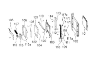
図1(a)は、デジタル一眼レフカメラの内部構造の分解斜視図である。不図示のカメラ本体内には、被写体側より、レンズを取り付けるマウント部を有するミラーボックス10と、フォーカルプレンシャッタ式のシャッタユニット20と、メインフレーム50と、異物除去機構を含む撮像素子ユニット100とが配置される。図1(b)は、これら構成要素を組み立てた状態を示す斜視図である。
Preferred embodiments of the present invention will be described below with reference to the accompanying drawings.
<First Embodiment>
FIG. 1A is an exploded perspective view of the internal structure of a digital single-lens reflex camera. In the camera body (not shown), from the subject side, a
図2(a)、図2(b)は、それぞれ図1(a)、図1(b)の状態を撮像素子側から見た斜視図である。 2A and 2B are perspective views of the states of FIGS. 1A and 1B as viewed from the image sensor side, respectively.
(撮像素子ユニット100)
図3及び図4を参照して、撮像素子ユニット100の構成及び動作について説明する。図3は、撮像素子ユニット100の分解斜視図である。図4は、撮像素子ユニット100を組み立てた状態を示す斜視図であり、(a)は異物除去部材が退避した状態を示し、(b)は異物除去部材がLPF104の下端に移動した状態を示す。
(Image sensor unit 100)
With reference to FIG.3 and FIG.4, the structure and operation | movement of the image pick-
ベース板102の背面側には撮像素子101が取り付けられ、被写体側となる表面側には後述する他の部品が組み付けられる。
The
ベース板102の表面側において撮像素子101の一方の短辺側にはモータアングル109が配置される。モータアングル109は撮像素子101の短辺(側辺)と平行に延伸する形状を有し、駆動モータ110と、駆動モータ110の回転出力軸に固定されたリードスクリュ111と、異物除去部材の移動をガイドするガイドバー112とが組み付けられる。
A
また、ベース板102の表面側において撮像素子101の他方の短辺側にはガイドアングル113が配置される。すなわち、ガイドアングル113は撮像素子101を挟んでモータアングル109と対向するように配置される。ガイドアングル113は撮像素子101の短辺(側辺)と平行に延伸する形状を有し、ガイドバー114が組み付けられる。
A
撮像素子101の前方には、LPF枠103に嵌め込まれたローパスフィルタ(LPF)104が配設される。LPF104は、不要な周波数成分等をカットすることで偽色やモアレの発生を抑える役割を果たす光学部材である。LPF104の左右に反射防止マスク(画枠マスク)105を位置決めした後、LPF固定枠106をLPF枠103に固定し、LPF104を固定する。
A low-pass filter (LPF) 104 fitted in the
このようにLPF104を挟んで駆動部(モータアングル109等)及びガイド部(ガイドアングル113等)が配置される。駆動部(モータアングル109等)及びガイド部(ガイドアングル113等)は異物除去部材(支持板108及び植毛部材107)を往復移動させて、LPF104の表面に付着した異物を除去する。
In this way, the drive unit (
具体的には、支持板108の一端が駆動ガイド115にネジで固定され、駆動ガイド115がガイドバー112に沿って移動可能とされている。尚、ガイドバー112は、駆動ガイド115を挿通させた後、モータアングル109に固定される。更に、駆動ガイド115には駆動ラック116が固定され、駆動ラック116がリードスクリュ111に連結する。駆動ラック116は、リードスクリュ111と同じネジ山のピッチを有する。
Specifically, one end of the
また、支持板108の他端には平面板部及びL字状の曲げ部が隣接して設けられており、ガイドバー114を挟み込むかたちでガイドバー114に係合する。
Further, a flat plate portion and an L-shaped bent portion are provided adjacent to the other end of the
駆動モータ110の回転力はリードスクリュ111から駆動ラック116に伝達され、駆動ガイド115がガイドバー112に沿って移動し、異物除去部材を往復移動させることになる。
The rotational force of the
異物除去部材において、支持板108の中央部にはLPF104側から離れる方向に凹む部位が形成される。ここでは、支持板108の中央部が一段下がるように曲げ加工された曲げ部が形成されており、そこに植毛部材107が接着固定される。支持板108に曲げ部を設けて植毛部材107を設けるようにしたので、長い毛で構成された植毛紙やブラシ等を接着固定することができる。この構成により、異物除去動作時にLPF104の表面への接触圧力の調整が容易になるという効果が得られる。つまり、毛を長くしたことで弾性が低くなり、僅かな接触状態の変化でも圧力変動が少なく、部品形状のバラツキにより植毛部材107とLPF104の表面との間隔誤差が生じても異物除去能力のバラツキを少なくすることができる。また、毛が変形してLPF104の表面に接触するようになるので、接触面積が増え、異物除去能力が向上するという効果もあり、異物が粘着性のある物質や液体であっても除去することも可能となる。
In the foreign matter removing member, a portion recessed in the direction away from the
このように支持板108に曲げ部を形成する分、その曲げ部がシャッタユニット20側に突出することになるが、後述するようにシャッタユニット20と干渉しないように構成されている。
Thus, the bent portion protrudes toward the
尚、支持板108は駆動ガイド115にネジで固定されているが、このネジを外し、支持板108をガイドバー114を中心として回転させて立たせることにより、植毛部材107の交換等を容易に行うことができる。
The
LPF104の端面のうち異物除去部材の走査方向にある上端面にはLPFガイド121が、下端面には異物捕獲部122が取り付けられている。
An
LPFガイド121は異物除去部材の退避位置側に設けられ、植毛部材107がLPF104の上端面に接触する際に削られてしまうのを防止するものである。LPFガイド121は、LPF104の表面と同一面に固定され、樹脂やゴム等の植毛部材107より柔らかい材料で、植毛部材107との接触部はR形状とし接触の圧力や摩擦を緩和するようになっている。
The
異物捕獲部122は、異物除去部材がLPF104の下端面付近に移動した際に、植毛部材107から落下したり、植毛部材107に付着したりしている異物を捕獲するための粘着性部材である。
The foreign
また、異物除去部材が退避位置からLPF104の表面上に移動する過程で植毛部材107を清掃する回転除去部119を備える。回転除去部119は、LPF固定枠106に回転可能に軸支され、左右にばね120を有する。
In addition, a
異物除去動作を開始して、異物除去部材が退避位置からLPF104の表面上に移動する際に、植毛部材107が回転除去部119に接触するが、この方向では回転除去部119がLPF固定枠106の壁部に接触して回転不能となっている。したがって、異物除去部材が移動する過程で回転除去部119が固定部材として存在することで、植毛部材107に付着している異物をLPF104よりも上方に払い落とすことができる。
When the foreign matter removing operation is started and the foreign matter removing member moves from the retracted position onto the surface of the
一方、植毛部材107がLPF104の表面上から退避位置に退避する際に、植毛部材107が回転除去部119に接触するが、この方向では回転除去部119が回転可能となっている。したがって、植毛部材107は回転除去部119をばね120の弾性力に抗して回転させることになる。すなわち、植毛部材107に付着している異物をそれほど払い落とすことなく異物除去部材が退避位置に移動することになり、異物がLPF104の表面に再付着するのを防止している。
On the other hand, when the flocked
ところで、植毛部材107をLPF104の表面に接触させながら移動させるときに、植毛部材107の接触状態が適切でないと、異物除去が不十分な部分が生じたり、圧力が掛かりすぎてLPF104の表面に疵をつけたりするという問題が生じる。そこで、異物除去部材のLPF104の表面に対する走査高さを調整できるようにしている。具体的には、モータアングル109及びガイドアングル113を固定する際に、ベース板102との間に皿ばね117を介在させる。モータアングル109の高さや傾きを調整する皿ばね117a、117b、ガイドアングル113の高さや傾きを調整する皿ばね117c、117dを、それぞれのアングルを固定するネジと同軸上に配置する。これにより、各ネジの締め込み量を調整して、異物除去部材の走査範囲においてLPF104との接触状態が一定になるように調整することが可能となる。
By the way, when the flocking
モータアングル109の背面には2つのホトインタラプタ(PI)118が接着固定される。駆動ガイド115に設けられたPI遮蔽部115aがPI118に挿入する関係にすることで、異物除去動作が完了したか否かを検知できるようになっている。
Two photo interrupters (PI) 118 are bonded and fixed to the back surface of the
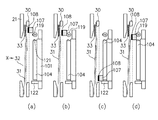
次に、図5を参照して、異物除去動作について説明する。異物除去動作の開始前(図5(a))、異物除去部材(支持板108及び植毛部材107)は退避位置にある。異物除去動作を開始すると(図5(b))、異物除去部材が退避位置から下方に移動し、植毛部材107が回転除去部119に接触する。この方向では回転除去部119の回転が規制されており、植毛部材107に付着している異物がLPF104よりも上方に払い落とされる。尚、植毛部材107が回転除去部119を通過するときに、植毛部材107から異物を払い落とすだけでなく、毛の変形を防止する効果もある。
Next, the foreign matter removing operation will be described with reference to FIG. Prior to the start of the foreign substance removal operation (FIG. 5A), the foreign substance removal members (the
異物除去部材が更に下方に移動し、LPF104の上端面に設けられたLPFガイド121に除々に接触して、LPF104の表面上に移動する。植毛部材107がLPF104の表面に接触しながら移動することにより、LPF104の表面に付着した異物を除去する。異物除去部材がLPF104の下端に到達すると(図5(c))、植毛部材107が異物捕獲部122に接触し、植毛部材107に付着している異物が異物捕獲部122により捕獲される。ここでは、異物捕獲部122が粘着性部材であるので、植毛部材107に付着した異物が吸着される。
The foreign matter removing member further moves downward, gradually contacts the
その後、モータ通電方向を逆にすることにより、異物除去部材が上方に移動し、植毛部材107が回転除去部119に接触する(図5(d))。この方向では回転除去部119の回転が許容されており、植毛部材107は回転除去部119を回転させながら僅かな接触力で回転除去部119を乗り越えて退避位置に復帰する。
Thereafter, by reversing the motor energization direction, the foreign matter removing member moves upward, and the flocking
(シャッタユニット20)
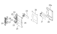
図6及び図7を参照して、シャッタユニット20の構成及び動作について説明する。図6は、シャッタユニット20の分解斜視図である。図7は、シャッタユニット20を組み立てた状態を示す斜視図であり、(a)はシャッタユニット20を被写体側から見た状態を示し、(b)は撮像面側から見た状態を示す。なお、シャッタユニット20は撮影光路中において、LPF104より被写体側(マウント側)に配設されている。
(Shutter unit 20)
The configuration and operation of the
シャッタユニット20は、先羽根群(先幕)31及び後羽根群(後幕)33の2組のシャッタ羽根を備えている。先幕31は、撮影前に撮影開口を遮蔽し、撮影開始信号により撮影光路から退避する。尚、先幕31が撮影光路から退避する移動方向は下方向となっている。後幕33は、撮影開始前に撮影光路から退避しており、撮影開始信号により、先幕走行から所定の時間の後、走行して撮影開口を遮蔽する。
The
これら2組の幕31、33は、シャッタプレート21とカバー板30との間に配置される。先幕31がカバー板30側に配置され、後幕33がシャッタプレート21側に配置され、中間板32により互いに干渉しないように走行空間が仕切られている。シャッタプレート21、中間板32、カバー板30それぞれの略中央位置には撮影開口(撮影光路用の開口)が形成されている。
These two sets of
シャッタプレート21にはシャッタ駆動部が設けられる。具体的には、先幕31を駆動するための先駆動レバー22及び駆動源となる先駆動ばね23、後幕33を駆動するための後駆動レバー24及び駆動源となる後駆動ばね25、セットレバー26を備える。セットレバー26は、先駆動レバー22と後駆動レバー24とを回転させてそれぞれの駆動ばね23、25チャージし、撮影開始前状態にセットするためのものである。シャッタ駆動部の上方には、シャッタ駆動部を制御する制御部として、ヨークとコイルとから構成される先幕用電磁石27及び後幕用電磁石28と、コイルに通電するための配線基板29とが設置される。
The
カバー板30は先幕31のLPF104側への作動範囲を規制する押え板として機能するものであり、撮影開口の上方に連続する開口部30aが形成されている。開口部30aは異物除去部材の退避位置となるものであり、異物除去部材が退避位置にあるときに支持板108の曲げ部が収容される。また、図7(b)に示すように、カバー板30の撮像面側では、撮影開口及び開口部30aまわりが薄肉部30bとされており、この薄肉部30bにより形成される空間を異物除去部材(支持板108の曲げ部を除く)が移動する。尚、開口部30aを更に上方に大きくし、カバー板30の上部が切り離された状態(カバー板30の上部が完全に開放された状態)として、異物除去部材の退避スペースを広げるようにしてもよい。
The
次に、シャッタ動作について説明する。先駆動レバー22及び後駆動レバー24はそれぞれ鉄片部を備え、撮影開始前状態ではヨークと鉄片部が接触している。撮影開始信号により先幕用及び後幕用の電磁石のコイルに通電されると、ヨークと鉄片部が吸着し、セットレバー26が退避した後も先幕31及び後幕33はセット状態に保持される。
Next, the shutter operation will be described. The
不図示の反射ミラーの退避やオートフォーカス制御、撮像素子101のリセット等が完了し、撮影可能状態となった後、先幕用のコイル通電が絶たれると、先駆動ばね23の駆動力により先幕31が走行する。そして、所定の時間の後、後幕用のコイル通電が絶たれると、後駆動ばね25の駆動力により後幕33が走行し、露光動作が行われる。セットレバー26を図示しないチャージレバーによりセットして先幕31、後幕33をそれぞれ撮影開始前状態として一連の動作が完了する。
After the retracting of the reflecting mirror (not shown), autofocus control, resetting of the
(カバー板30と異物除去部材との位置関係)
ここで、従来におけるカバー板と異物除去部材との位置関係と、本実施形態におけるカバー板と異物除去部材との位置関係との比較を行う。図17は、従来技術による異物除去機構まわりの構成を模式的に示す図である。尚、比較しやすいように、本実施形態で説明した構成要素に対応するものには同一の符号を付して説明する。被写体側より、シャッタプレート21、後幕33、中間板32、先幕31、カバー板30、異物除去部材(支持板108及び植毛部材107)、LPF104、撮像素子101等が配置されている。
(Position relationship between
Here, the conventional positional relationship between the cover plate and the foreign matter removing member is compared with the positional relationship between the cover plate and the foreign matter removing member in the present embodiment. FIG. 17 is a diagram schematically showing a configuration around a foreign matter removing mechanism according to the prior art. For ease of comparison, components corresponding to those described in this embodiment will be described with the same reference numerals. From the subject side, a
図17(a)は異物除去部材が退避した状態を示し、異物除去部材はカバー板30の背面に退避している。図17(b)は異物除去動作中の状態を示し、異物除去部材がLPF104の下端に達している。従来の構成においては、異物除去部材がカバー板30とLPF104との隙間を移動するため、寸法に制限が生じ、植毛部材107の毛の長さを十分に確保することができない。毛が短いことで剛性が上がり、LPF104の表面に疵を付けてしまうおそれがある。また、走査全域で同じ接触状態とすることが難しく、異物の取り残しも生じやすい。カバー板30やLPF104を薄くする等してカバー板30とLPF104との隙間を確保することも容易ではなく、シャッタ性能や光学性能に影響を及ぼすおそれもある。
FIG. 17A shows a state where the foreign matter removing member is retracted, and the foreign matter removing member is retracted to the back surface of the
一方、図5に示したように、本実施形態でも、被写体側より、シャッタプレート21、後幕33、中間板32、先幕31、カバー板30、異物除去部材(支持板108及び植毛部材107)、LPF104、撮像素子101等が配置されている。
On the other hand, as shown in FIG. 5, also in this embodiment, from the subject side, the
ただし、図5(a)に示すように、異物除去部材が退避した状態で、異物除去部材の支持板108の曲げ部がカバー板30の開口部30aに収容され、異物除去部材の一部がカバー板30の厚み内に収まっている。本実施形態では、支持板108の曲げ部の深さは、カバー板30の先幕31側の面を超えて突出しない程度の深さとなっている。しかも、異物除去部材の退避位置がカバー板30の上方にあり、先幕31の退避方向(下方向)とは逆側にあるので、異物除去部材が先幕31の動作に干渉することはない。また、後幕33は中間板32よりも被写体側に配置されているので、異物除去部材が後幕33の動作に干渉することもなく、シャッタ動作には何ら支障がない。この構成においては、異物除去部材用のスペースが従来よりも広くなり、植毛部材107の毛の長さを長くすることが可能となる。尚、異物除去部材の退避位置では植毛部材107は他の部材と接触しておらず、毛が変形するおそれはない。
However, as shown in FIG. 5A, the bent portion of the
また、上述した異物除去動作の間、シャッタは動作が禁止されており、ユーザには異物除去動作中であることを表示モニタ等に表示して通知する(本発明でいう通知手段による処理例)。異物除去動作中は、シャッタユニット20の先幕31で撮影開口を覆ったままとし、外部からの異物の進入を防ぐようにする。
Further, during the foreign matter removing operation described above, the shutter is prohibited from operating, and the user is notified by displaying on the display monitor or the like that the foreign matter removing operation is being performed (example of processing by the notification means in the present invention). . During the foreign substance removal operation, the photographing opening is kept covered with the
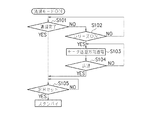
図8には、異物除去動作(清掃動作)中に撮影指示があった場合の動作シーケンスを示す。異物除去動作中において、PI118及びPI遮蔽部115aによるPI信号等により異物除去動作が完了したか否かを判定する(ステップS101)。異物除去動作が完了していない状態でレリーズボタンが押下されると(ステップS102)、異物除去動作を強制終了させるために、モータ通電を退避方向に切り替えて(ステップS103)、異物除去部材を退避位置に退避させる。異物除去部材が退避したことを確認した後(ステップS104)、シャッタを撮影可能状態にセットする(ステップS105)。その際、通常よりも高速に退避できるようにモータへの電圧を高くするようにすると、シャッタチャンスを逃すことを防止することができる。
FIG. 8 shows an operation sequence when a photographing instruction is given during the foreign substance removal operation (cleaning operation). During the foreign matter removing operation, it is determined whether or not the foreign matter removing operation is completed by a PI signal or the like by the
尚、本実施形態では、本発明でいう光学部材としてLPF104の表面に付着した異物を除去する構成を説明したが、他のフィルタ類や撮像素子101の表面(カバーガラスの表面)に付着した異物を除去する構成としてもよい。
In the present embodiment, the configuration for removing foreign matter attached to the surface of the
また、本実施形態のシャッタ構成以外にも様々なタイプのフォーカルプレンシャッタがあり、シャッタ構成は限定されるものではない。要は、LPF104に近い側を走行するシャッタ羽根の退避方向とは逆側に開口部30aを設け、異物除去部材の退避位置として利用できるように構成すればよい。したがって、先幕・後幕の配置や走行方向にも限定されることはなく、撮影開始前状態で撮影開口を開放して被写体像をモニタ表示できるようにしたノーマリオープンタイプのシャッタにも適用可能である。また、シャッタ羽根が1組しかなく、撮像素子自体のシャッタ機能により露出制御し、露光完了時に撮影開口を遮蔽して不要光をカットするタイプのシャッタにも適用可能である。
In addition to the shutter configuration of the present embodiment, there are various types of focal plane shutters, and the shutter configuration is not limited. In short, the
以上述べたように、カバー板30と異物除去部材の一部とを光軸X(図5を参照)に垂直な同一平面上に位置させることにより、コンパクト化を図るとともに、シャッタ性能や異物除去能力を低下させることなく異物除去機構を設置することができる。
As described above, the
<第2の実施形態>
図9及び図10を参照して、第2の実施形態を説明する。以下では、上記第1の実施形態と異なる点を中心に説明し、同一の構成及び動作の説明は省略する。第2の実施形態は、上記第1の実施形態と異物除去部材の支持板108の曲げ部の形状及び植毛部材107の形状が異なり、また、異物除去動作及びシャッタ動作シーケンスが異なる。
<Second Embodiment>
The second embodiment will be described with reference to FIGS. 9 and 10. Below, it demonstrates centering on a different point from the said 1st Embodiment, and abbreviate | omits description of the same structure and operation | movement. The second embodiment differs from the first embodiment in the shape of the bent portion of the
異物除去部材において、支持板108の中央部にはLPF104側から離れる方向に一段下がるように曲げ部が形成されるが、その深さが第1の実施形態よりも深くなっている。その結果、図9に示すように、支持板108の曲げ部は、カバー板30の先幕31側の面を超えて突出するようになっている。このように曲げ部を深くすることにより、植毛部材107の毛の長さを更に長くすることができ、LPF104への接触状態の調整が更に容易となり、異物除去性能の向上及びLPF104への疵付き防止を図ることができる。
In the foreign matter removing member, a bent portion is formed at the central portion of the
上記第1の実施形態では、先幕31の移動軌跡と異物除去部材の移動軌跡とは光軸に垂直な同一平面上になかった。それに対して、本実施形態では、支持板108の曲げ部がカバー板30の先幕31側の面を超えて突出するため、先幕31の移動軌跡と異物除去部材の移動軌跡とが少なくとも一部においてオーバーラップする。つまり、カバー板30と異物除去部材の少なくとも一部が光軸に垂直な同一平面上にあることになる。
In the first embodiment, the movement trajectory of the
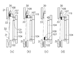
次に、図9及び図10を参照して、異物除去動作について説明する。異物除去動作を開始すると、まず撮像面側に配置されている先幕31を下方向に退避させ(ステップS201)、後幕33を展開させる(ステップS202)ことで撮影開口を遮蔽する。また、ユーザに異物除去動作中である旨を通知するために表示モニタに表示を行う(ステップS203)。このときの表示例を図10に示す。この表示は異物除去動作の完了まで継続される(ステップS205)。
Next, the foreign matter removing operation will be described with reference to FIGS. When the foreign matter removing operation is started, first, the
次に、異物除去部材を退避位置から下方に移動させる(図9(b))(ステップS204)。異物除去部材は先幕31の走行面を移動するが、先幕31が既に退避させられているので干渉することはない。尚、異物除去部材が退避位置から移動させ始めるタイミングは、先幕31を完全に撮影開口外へ退避させてからとする必要はなく、先幕31の移動と同時か、僅かに遅れるタイミングとしてもよい。
Next, the foreign matter removing member is moved downward from the retracted position (FIG. 9B) (step S204). The foreign matter removing member moves on the traveling surface of the
植毛部材107に付着している異物が回転除去部119で払い落とされた後、植毛部材107がLPF104の表面に接触しながら移動することにより、LPF104の表面に付着した異物を除去する。異物除去部材がLPF104の下端に到達すると(図9(c))、植毛部材107が異物捕獲部122に接触し、植毛部材107に付着している異物が異物捕獲部122により捕獲される。
After the foreign matter adhering to the flocking
その後、モータ通電方向を逆にすることにより、異物除去部材が上方に移動し、植毛部材107が回転除去部119に接触する(図9(d))。この方向では回転除去部119の回転が許容されており、植毛部材107は回転除去部119を回転させながら僅かな接触力で回転除去部119を乗り越えて退避位置に復帰する(ステップS205)。
Thereafter, by reversing the motor energization direction, the foreign matter removing member moves upward, and the flocking
続いて、先幕31、後幕33をセットし(ステップS206)、撮影可能状態としたところで異物除去動作が完了する(ステップS207)。
Subsequently, the
尚、第1の実施形態でも述べたように、異物除去動作中に撮影指示があった場合は、図8の動作シーケンスを実行することにより、迅速に撮影スタンバイ状態とすることができる。 As described in the first embodiment, when a photographing instruction is issued during the foreign substance removing operation, the photographing standby state can be quickly established by executing the operation sequence of FIG.
また、シャッタ羽根と異物除去部材との配置が上述のような関係になっているものであれば、先幕31が撮像面側で、後幕33が被写体側である必要はない。図9(a)の状態がシャッタ動作完了直後の状態であり、撮像面側で撮影開口を覆っているのが後幕、被写体側で上方に退避しているのが先幕としても成り立つ。この場合は、シャッタ羽根が下から上に露光動作することとなるが、何ら問題はない。
If the arrangement of the shutter blades and the foreign matter removing member is as described above, it is not necessary that the
<第3の実施形態>
図11及び図12を参照して、第3の実施形態を説明する。以下では、上記第1、2の実施形態と異なる点を中心に説明し、同一の構成及び動作の説明は省略する。第3の実施形態は、上記第2の実施形態と異物除去動作及びシャッタ動作シーケンスが異なる。
<Third Embodiment>
A third embodiment will be described with reference to FIGS. 11 and 12. Below, it demonstrates centering on a different point from the said 1st, 2nd embodiment, and abbreviate | omits description of the same structure and operation | movement. The third embodiment is different from the second embodiment in the foreign matter removing operation and the shutter operation sequence.
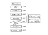
図11及び図12を参照して、異物除去動作について説明する。異物除去動作を開始すると、まず撮像面側に配置されている先幕31を下方向に退避させ(ステップS301)、撮影開口を開放する。反射ミラー等も退避させることで被写体像が撮像素子101に入射するので、被写体像を表示モニタに表示する(ステップS302)。被写体像に重畳して異物除去動作中である旨を通知する表示を行い(ステップS303)、この状態のまま異物除去部材を退避位置から下方に移動させる(図11(b))(ステップS304)。異物除去動作中にも撮像素子101の画像が表示モニタに映し出され、異物除去部材がLPF104の表面上を走査している様子を確認することができる。すなわち、被写体像と、異物除去部材の様子と、異物除去動作中である旨の表示とが重ねて表示されている。この表示は異物除去動作の完了まで継続される(ステップS305)。
The foreign substance removal operation will be described with reference to FIGS. When the foreign matter removing operation is started, first, the
植毛部材107に付着している異物が回転除去部119で払い落とされた後、植毛部材107がLPF104の表面に接触しながら移動することにより、LPF104の表面に付着した異物を除去する。異物除去部材がLPF104の下端に到達すると(図11(c))、植毛部材107が異物捕獲部122に接触し、植毛部材107に付着している異物が異物捕獲部122により捕獲される。
After the foreign matter adhering to the flocking
その後、モータ通電方向を逆にすることにより、異物除去部材が上方に移動し、植毛部材107が回転除去部119に接触する(図11(d))。この方向では回転除去部119の回転が許容されており、植毛部材107は回転除去部119を回転させながら僅かな接触力で回転除去部119を乗り越えて退避位置に復帰する(ステップS305)。
Thereafter, by reversing the motor energization direction, the foreign matter removing member moves upward, and the flocking
続いて、先幕31をセットし(ステップS306)、先幕31で再び撮影開口を覆い、撮影待機状態となったところで異物除去動作が完了した旨を表示モニタに表示する(ステップS307)。
Subsequently, the
尚、第1の実施形態でも述べたように、異物除去動作中に撮影指示があった場合は、図8の動作シーケンスを実行することにより、迅速に撮影スタンバイ状態とすることができる。 As described in the first embodiment, when a photographing instruction is issued during the foreign substance removing operation, the photographing standby state can be quickly established by executing the operation sequence of FIG.
第1の実施形態で述べたタイプのシャッタユニットでは、撮影開口を開放するため、先幕だけを走行させ、後幕を退避状態に保持するには、後幕用のコイルに通電を続ける必要がある。他のシャッタ機構においては、無通電で後幕を保持できるものや、モータ等でダイレクトに羽根を駆動するものも知られており、これらのシャッタユニットを利用することで清掃動作中のシャッタへの通電を無くすこともできる。 In the shutter unit of the type described in the first embodiment, in order to open only the front curtain and keep the rear curtain in the retracted state in order to open the photographing aperture, it is necessary to continue energizing the rear curtain coil. is there. Other shutter mechanisms are also known that can hold the trailing curtain without being energized, and those that directly drive the blades with a motor or the like. By using these shutter units, the shutters during the cleaning operation can be used. It can also be turned off.
また、ノーマリオープンタイプと称される、先幕及び後幕の両方を撮影開口外に退避したシャッタを用いた場合は、撮影開始前状態が図11(b)の状態になっており、被写体像が常に撮像素子に入射していることとなる。このような場合には、異物除去部材が退避した時に先幕で撮影開口を覆うことなく異物除去動作が完了した旨を表示モニタに表示すればよいことは言うまでもない。 In addition, when a shutter that is referred to as a normally open type and in which both the front curtain and the rear curtain are retracted outside the photographing aperture is used, the state before the photographing start is in the state of FIG. The image is always incident on the image sensor. In such a case, it is needless to say that the foreign matter removing operation is completed on the display monitor without covering the photographing opening with the front curtain when the foreign matter removing member is retracted.
<第4の実施形態>
図13を参照して、第4の実施形態を説明する。以下では、上記第1〜3の実施形態と異なる点を中心に説明し、同一の構成及び動作の説明は省略する。第4の実施形態は、上記第3の実施形態とシャッタ羽根の構成が異なる。
<Fourth Embodiment>
The fourth embodiment will be described with reference to FIG. Below, it demonstrates centering on a different point from the said 1st-3rd embodiment, and abbreviate | omits description of the same structure and operation | movement. The fourth embodiment is different from the third embodiment in the configuration of the shutter blades.
図13に示すように、シャッタプレート21とカバー板30との間には1組のシャッタ羽根44しか存在せず、露光量の制御を撮像素子101自体の電荷蓄積時間制御で行う。シャッタ羽根44は撮像素子101への不要な入射光を遮蔽するために用いられる。若しくは、撮像素子101により電荷蓄積の開始タイミングを制御し、シャッタ羽根44により電荷蓄積終了タイミングを制御するタイプにも適用できる。
As shown in FIG. 13, there is only one set of
このような1組のシャッタ羽根で構成される場合にも、上述した実施形態と同様に、シャッタ羽根の退避方向とは逆側に異物除去部材が退避できるようにカバー板30に開口部30aを形成する。この構成により、図13(a)に示すように、シャッタ羽根44が撮影開口を遮蔽した状態でも、異物除去部材はシャッタ羽根44と干渉することがない。異物除去動作を開始する場合には、図13(b)に示すように、まずシャッタ羽根44を下方に退避させた後、図13(c)、図13(d)に示すように、異物除去部材を退避位置から移動させてLPF104の表面上を走査させる。
Even in the case of such a set of shutter blades, as in the above-described embodiment, the
<第5の実施形態>
図14を参照して、第5の実施形態を説明する。以下では、上記第1〜4の実施形態と異なる点を中心に説明し、同一の構成及び動作の説明は省略する。第5の実施形態は、上記第2の実施形態と異物除去部材の構成が異なる。
<Fifth Embodiment>
The fifth embodiment will be described with reference to FIG. Below, it demonstrates centering on a different point from the said 1st-4th embodiment, and abbreviate | omits description of the same structure and operation | movement. The fifth embodiment is different from the second embodiment in the configuration of the foreign matter removing member.
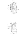
支持板108には、帯電部材201が取り付けられている。また、LPF104の上方には、帯電部202及び除電部203が配置されている。図14(a)は異物除去動作前の状態を示し、支持板108の一部がカバー板30の先幕31側の面を超えて突出するようになっている。
A charging
異物除去動作を開始すると、先幕31を下方に退避させ、後幕33を展開させることで撮影開口を遮蔽する。次に、異物除去部材を退避位置から下方に移動させるが、異物除去部材が帯電部202上を通過する際に、帯電部材201に電荷が蓄えられる(図14(b))。そして、帯電部材201がLPF104の表面近傍を非接触で移動することにより、LPF104の表面に付着した異物を静電気力により吸引、除去する。
When the foreign matter removal operation is started, the
異物除去部材がLPF104の下端に到達した後(図14(c))、モータ通電方向を逆にすることにより、異物除去部材が上方に移動する。異物除去部材が除電部203上を通過する際、帯電部材201から電化が除かれ、帯電部材201に付着していた異物が落下する(図14(d))。尚、除電部203の周囲には、落下する異物を捕獲する粘着部が設けられている。続いて、チャージして先幕31で撮影開口を覆い、撮影待機状態とする。
After the foreign matter removing member reaches the lower end of the LPF 104 (FIG. 14C), the foreign matter removing member moves upward by reversing the motor energizing direction. When the foreign matter removing member passes over the static eliminating
<第6の実施形態>
図15及び図16を参照して、第6の実施形態を説明する。以下では、上記第1〜4の実施形態と異なる点を中心に説明し、同一の構成及び動作の説明は省略する。第6の実施形態は、上記第2の実施形態と異物除去部材の構成が異なる。
<Sixth Embodiment>
The sixth embodiment will be described with reference to FIGS. 15 and 16. Below, it demonstrates centering on a different point from the said 1st-4th embodiment, and abbreviate | omits description of the same structure and operation | movement. The sixth embodiment is different from the second embodiment in the configuration of the foreign matter removing member.
支持板108には、板ばね部材302を介してワイパ301が取り付けられている。また、LPF104の上方には、除去部303、LPF104の下方には粘着部304が配置されている。図15(a)は異物除去動作前の状態を示し、支持板108の一部がカバー板30の先幕31側の面を超えて突出するようになっている。
A
異物除去動作を開始すると、先幕31を下方に退避させ、後幕33を展開させることで撮影開口を遮蔽する。次に、異物除去部材を退避位置から下方に移動させるが、異物除去部材が除去部303上を通過する際に、ワイパ301に付着していた異物が除去される。そして、ワイパ301がLPF104の表面上を移動するとき、ワイパ301が変形しながらLPF104の表面に接触する(図15(b))。支持板108とワイパ301との間に板ばね部材302を介在させておき、ワイパ301が変形してもLPF104の表面との接触状態が変わらないようにしている。ワイパ301はゴムで成形されたものであり、植毛紙よりも剛性が高く、変形しにくい。したがって、LPF104への圧力を一定にするために、支持板108とワイパ301との間に、ワイパ301よりも弾性が低い板ばね部材を配置したものである。支持板108とLPF104との間隔が多少変化しても、板ばね部材302が吸収し、ワイパ301をLPF104の表面に一定の圧力で接触させることができる。
When the foreign matter removal operation is started, the
異物除去部材がLPF104の下端に到達すると(図15(c))、ワイパ301が粘着部304に接触し、ワイパ301に付着している異物が粘着部304により捕獲される。その後、モータ通電を逆にすることにより、異物除去部材が上方に移動する。異物除去部材が除去部303上を通過する際に、ワイパ301に付着していた異物が除去される(図15(d))。続いて、チャージして先幕31で撮影開口を覆い、撮影待機状態とする。
When the foreign matter removing member reaches the lower end of the LPF 104 (FIG. 15C), the
図16は、本実施形態における異物除去部材の構成例を示す斜視図であり、(a)は異物除去部材を分解した状態を示し、(b)は組み立てた状態を示す。支持板108の曲げ部に、複数の曲げ部を有する板ばね部材302が固定される。ゴム製のワイパ301は金属板310に接着されており、板ばね部材302が伸縮変形可能なように板ばね部材302の両端が金属板310にネジで固定される。
FIG. 16 is a perspective view illustrating a configuration example of the foreign matter removing member in the present embodiment, where (a) shows a state where the foreign matter removing member is disassembled, and (b) shows an assembled state. A
尚、図16には、横断面が波形状のワイパ301を示したが、ワイパの形状は図示したものに限定されるものではない。
FIG. 16 shows the
このように支持板108とワイパ301との間に弾性部材を介在させる構成により、拭き残しを無くし、圧力を一定に保持するとともに、温度、湿度や作動回数による摩耗、変形による圧力変動も緩和することができる。尚、上述した実施形態で説明した植毛部材107を用いる場合にも、支持板108と植毛部材107との間に弾性部材を介在させてもよい。本発明の構成により、支持板108とワイパ301との間に弾性部材を介在させるだけのスペースを確保できるようになり、従来よりも異物除去能力を向上させることができる。
In this way, the configuration in which the elastic member is interposed between the
尚、異物除去部材は上述した実施形態のものに限られず、光学部材の表面に沿って移動することにより異物を除去するものであれば、光学部材の表面に接触するものでもよいし、非接触のものでもよい。支持板108とLPF104の表面との間隔を十分確保できる構成となっているので、光学部材の表面に付着した異物を除去する除去部材として、第1〜4の実施形態で示した植毛部材107、第5の実施形態で示した電気的な吸引力を働かせる帯電部材201、第6の実施形態で示したワイパ301以外にも考えられる。例えばスポンジ、不織布、ゴム等でもよく、粘着ローラや回転ブラシ等でもよい。また、エア吹き出し口を有するエア吹き出し装置としてもよい。更に、これらを複数組み合わせた異物除去部材を構成してもよい。
The foreign matter removing member is not limited to that of the above-described embodiment, and may be in contact with the surface of the optical member as long as the foreign matter is removed by moving along the surface of the optical member. It may be. Since the space between the
10 ミラーボックス
20 シャッタユニット
21 シャッタプレート
30 カバー板
31 先羽根群(先幕)
32 中間板
33 後羽根群(後幕)
44 シャッタ羽根
50 メインフレーム
100 撮像素子ユニット
101 撮像素子
102 ベース板
104 LPF(ローパスフィルタ)
107 植毛部材
108 支持板
109 モータアングル
110 モータ
111 リードスクリュ
112 ガイドバー
113 ガイドアングル
114 ガイドバー
115 駆動ガイド
116 ラック
201 帯電部材
301 ワイパ
302 板ばね
10
32
44
DESCRIPTION OF
Claims (3)
前記光学部材より被写体側に配設されて撮影光路を開放、遮蔽するシャッタ羽根とを備え、
前記異物除去部材は前記シャッタ羽根とは独立して移動するものであって、前記異物除去部材の移動軌跡と前記シャッタ羽根の移動軌跡とが光軸に垂直な同一平面上にあり、前記シャッタ羽根が前記撮影光路を開放するときに、前記異物除去部材は前記光学部材の表面に沿って移動することを特徴とする撮像装置。 A foreign matter removing member that removes foreign matter by moving along the surface of the optical member;
A shutter blade that is disposed closer to the subject than the optical member and opens and shields the photographing optical path;
The foreign matter removal member moves independently of the shutter blade, and the movement locus of the foreign matter removal member and the movement locus of the shutter blade are on the same plane perpendicular to the optical axis, and the shutter blade When the imaging optical path is opened, the foreign matter removing member moves along the surface of the optical member.
撮影時に撮影光路を遮蔽状態から開放状態に走行する第1のシャッタ羽根と、
撮影時に前記撮影光路を開放状態から遮蔽状態に走行する第2のシャッタ羽根とを備え、
前記異物除去部材の移動軌跡と前記第1のシャッタ羽根の移動軌跡とが光軸に垂直な同一平面上にあり、
前記異物除去部材の移動軌跡と前記第2のシャッタ羽根の移動軌跡とが光軸に垂直な同一平面上になく、
前記第1のシャッタ羽根が前記撮影光路を開放状態とし、前記第1のシャッタ羽根が前記撮影光路を遮蔽状態とするときに、前記異物除去部材は前記光学部材の表面に沿って移動することを特徴とする撮像装置。 A foreign matter removing member that removes foreign matter by moving along the surface of the optical member;
A first shutter blade that travels from a shielding state to an open state during photographing,
A second shutter blade that travels from the open state to the shielded state during shooting,
The movement locus of the foreign matter removing member and the movement locus of the first shutter blade are on the same plane perpendicular to the optical axis;
The movement locus of the foreign matter removing member and the movement locus of the second shutter blade are not on the same plane perpendicular to the optical axis,
The foreign matter removing member moves along the surface of the optical member when the first shutter blade opens the photographing optical path and the first shutter blade shields the photographing optical path. An imaging device that is characterized.
撮影時に撮影光路を遮蔽状態から開放状態に走行する第1のシャッタ羽根と、
撮影時に前記撮影光路を開放状態から遮蔽状態に走行する第2のシャッタ羽根とを備え、
前記異物除去部材の移動軌跡と前記第1のシャッタ羽根の移動軌跡とが光軸に垂直な同一平面上にあり、
前記異物除去部材の移動軌跡と前記第2のシャッタ羽根の移動軌跡とが光軸に垂直な同一平面上になく、
前記第1のシャッタ羽根が前記撮影光路を開放状態とし、前記第1のシャッタ羽根が前記撮影光路を開放状態とするときに、前記異物除去部材は前記光学部材の表面に沿って移動することを特徴とする撮像装置。 A foreign matter removing member that removes foreign matter by moving along the surface of the optical member;
A first shutter blade that travels from a shielding state to an open state during photographing,
A second shutter blade that travels from the open state to the shielded state during shooting,
The movement locus of the foreign matter removing member and the movement locus of the first shutter blade are on the same plane perpendicular to the optical axis;
The movement locus of the foreign matter removing member and the movement locus of the second shutter blade are not on the same plane perpendicular to the optical axis,
When the first shutter blade opens the photographing optical path, and the first shutter blade opens the photographing optical path, the foreign matter removing member moves along the surface of the optical member. An imaging device that is characterized.
Priority Applications (3)
| Application Number | Priority Date | Filing Date | Title |
|---|---|---|---|
| JP2007337730A JP4968942B2 (en) | 2007-12-27 | 2007-12-27 | Imaging device |
| US12/323,342 US8041208B2 (en) | 2007-12-27 | 2008-11-25 | Imaging apparatus having foreign substance removal member which overlaps shutter blade moving locus in optical axis direction |
| CN2008101801247A CN101470329B (en) | 2007-12-27 | 2008-11-27 | Imaging apparatus |
Applications Claiming Priority (1)
| Application Number | Priority Date | Filing Date | Title |
|---|---|---|---|
| JP2007337730A JP4968942B2 (en) | 2007-12-27 | 2007-12-27 | Imaging device |
Publications (3)
| Publication Number | Publication Date |
|---|---|
| JP2009157253A JP2009157253A (en) | 2009-07-16 |
| JP2009157253A5 JP2009157253A5 (en) | 2010-12-02 |
| JP4968942B2 true JP4968942B2 (en) | 2012-07-04 |
Family
ID=40798579
Family Applications (1)
| Application Number | Title | Priority Date | Filing Date |
|---|---|---|---|
| JP2007337730A Expired - Fee Related JP4968942B2 (en) | 2007-12-27 | 2007-12-27 | Imaging device |
Country Status (3)
| Country | Link |
|---|---|
| US (1) | US8041208B2 (en) |
| JP (1) | JP4968942B2 (en) |
| CN (1) | CN101470329B (en) |
Families Citing this family (8)
| Publication number | Priority date | Publication date | Assignee | Title |
|---|---|---|---|---|
| JP5216034B2 (en) * | 2010-02-22 | 2013-06-19 | セイコープレシジョン株式会社 | Focal plane shutter and optical equipment |
| JP2012050016A (en) * | 2010-08-30 | 2012-03-08 | Olympus Imaging Corp | Imaging apparatus |
| US9436005B2 (en) | 2012-08-02 | 2016-09-06 | Gentex Corporation | Amplified piezoelectric camera lens cleaner |
| WO2018016508A1 (en) * | 2016-07-19 | 2018-01-25 | キヤノン電子株式会社 | Blade drive device and imaging device |
| CN110394335B (en) * | 2018-04-24 | 2022-09-06 | 塔工程有限公司 | Optical device |
| JP6827509B1 (en) * | 2019-10-11 | 2021-02-10 | 浜松ホトニクス株式会社 | Manufacturing method of mirror device and manufacturing method of mirror unit |
| DE102021112096A1 (en) * | 2021-05-10 | 2022-11-10 | Bayerische Motoren Werke Aktiengesellschaft | Method and device for operating a windscreen display system with a cover detection and windscreen display system |
| DE102021112097A1 (en) * | 2021-05-10 | 2022-11-10 | Bayerische Motoren Werke Aktiengesellschaft | Method and device for operating a windscreen display system with a cover detection and windscreen display system |
Family Cites Families (11)
| Publication number | Priority date | Publication date | Assignee | Title |
|---|---|---|---|---|
| JP2001298640A (en) | 2000-04-17 | 2001-10-26 | Canon Inc | Digital camera |
| JP4243417B2 (en) * | 2000-06-15 | 2009-03-25 | Hoya株式会社 | Electronic camera |
| US7492408B2 (en) * | 2002-05-17 | 2009-02-17 | Olympus Corporation | Electronic imaging apparatus with anti-dust function |
| JP2005173104A (en) * | 2003-12-10 | 2005-06-30 | Nikon Corp | Lens barrel and camera |
| JP2005292404A (en) | 2004-03-31 | 2005-10-20 | Canon Inc | Accessory device |
| JP2006119461A (en) * | 2004-10-22 | 2006-05-11 | Canon Inc | Optical apparatus and control method thereof |
| JP2007052076A (en) * | 2005-08-15 | 2007-03-01 | Canon Inc | Focal plane shutter and imaging device |
| JP2007183366A (en) * | 2006-01-05 | 2007-07-19 | Pentax Corp | Dust-proof light-transmitting member, use thereof, and image pickup apparatus including the member |
| JP4773841B2 (en) * | 2006-02-17 | 2011-09-14 | キヤノン株式会社 | Imaging device |
| JP4819575B2 (en) * | 2006-05-26 | 2011-11-24 | キヤノン株式会社 | Imaging device |
| JP5058613B2 (en) * | 2007-01-23 | 2012-10-24 | キヤノン株式会社 | Imaging device |
-
2007
- 2007-12-27 JP JP2007337730A patent/JP4968942B2/en not_active Expired - Fee Related
-
2008
- 2008-11-25 US US12/323,342 patent/US8041208B2/en not_active Expired - Fee Related
- 2008-11-27 CN CN2008101801247A patent/CN101470329B/en not_active Expired - Fee Related
Also Published As
| Publication number | Publication date |
|---|---|
| US20090169196A1 (en) | 2009-07-02 |
| US8041208B2 (en) | 2011-10-18 |
| CN101470329B (en) | 2011-04-20 |
| CN101470329A (en) | 2009-07-01 |
| JP2009157253A (en) | 2009-07-16 |
Similar Documents
| Publication | Publication Date | Title |
|---|---|---|
| JP4968942B2 (en) | Imaging device | |
| JP5118751B2 (en) | Camera body and imaging device | |
| US7057642B2 (en) | Electronic camera with device for eliminating static electric charges from optical element | |
| JP5743509B2 (en) | Shutter device | |
| KR101490754B1 (en) | Shutter device | |
| US11516371B2 (en) | Cleaning apparatus for a detection surface of a detection element | |
| US7598978B2 (en) | Imaging apparatus | |
| KR101491631B1 (en) | Shutter device | |
| JP2016090739A (en) | Shutter device and imaging device | |
| JP2006100875A (en) | Digital camera cleaning method and cleaning system | |
| JP2018081117A (en) | IMAGING DEVICE, IMAGING DEVICE CONTROL METHOD, AND PROGRAM | |
| JP2009163209A (en) | camera | |
| JP5274333B2 (en) | Imaging device | |
| JP4609663B2 (en) | Imaging device | |
| JP5159349B2 (en) | Imaging device | |
| JP2007052076A (en) | Focal plane shutter and imaging device | |
| JP4693728B2 (en) | Imaging device | |
| JP4311077B2 (en) | Electronic camera | |
| JP2005005972A (en) | Image sensor cleaning device and camera system provided with the same | |
| JP2007325106A (en) | Electronic camera, cleaning member, and electronic camera cleaning method | |
| JP2009267534A (en) | Imaging apparatus | |
| JP2007240663A (en) | Imaging device and cleaning method in imaging device | |
| JP5339982B2 (en) | Imaging device | |
| JP2015111251A (en) | Imaging device | |
| JP2009162949A (en) | Foreign matter removing device and imaging device |
Legal Events
| Date | Code | Title | Description |
|---|---|---|---|
| A521 | Request for written amendment filed |
Free format text: JAPANESE INTERMEDIATE CODE: A523 Effective date: 20101012 |
|
| A621 | Written request for application examination |
Free format text: JAPANESE INTERMEDIATE CODE: A621 Effective date: 20101012 |
|
| A977 | Report on retrieval |
Free format text: JAPANESE INTERMEDIATE CODE: A971007 Effective date: 20120301 |
|
| TRDD | Decision of grant or rejection written | ||
| A01 | Written decision to grant a patent or to grant a registration (utility model) |
Free format text: JAPANESE INTERMEDIATE CODE: A01 Effective date: 20120306 |
|
| A01 | Written decision to grant a patent or to grant a registration (utility model) |
Free format text: JAPANESE INTERMEDIATE CODE: A01 |
|
| A61 | First payment of annual fees (during grant procedure) |
Free format text: JAPANESE INTERMEDIATE CODE: A61 Effective date: 20120402 |
|
| FPAY | Renewal fee payment (event date is renewal date of database) |
Free format text: PAYMENT UNTIL: 20150413 Year of fee payment: 3 |
|
| R151 | Written notification of patent or utility model registration |
Ref document number: 4968942 Country of ref document: JP Free format text: JAPANESE INTERMEDIATE CODE: R151 |
|
| FPAY | Renewal fee payment (event date is renewal date of database) |
Free format text: PAYMENT UNTIL: 20150413 Year of fee payment: 3 |
|
| LAPS | Cancellation because of no payment of annual fees |