JP4968355B2 - Method and apparatus for noise suppression - Google Patents
Method and apparatus for noise suppression Download PDFInfo
- Publication number
- JP4968355B2 JP4968355B2 JP2010068541A JP2010068541A JP4968355B2 JP 4968355 B2 JP4968355 B2 JP 4968355B2 JP 2010068541 A JP2010068541 A JP 2010068541A JP 2010068541 A JP2010068541 A JP 2010068541A JP 4968355 B2 JP4968355 B2 JP 4968355B2
- Authority
- JP
- Japan
- Prior art keywords
- unit
- suppression coefficient
- coefficient
- speech
- supplied
- Prior art date
- Legal status (The legal status is an assumption and is not a legal conclusion. Google has not performed a legal analysis and makes no representation as to the accuracy of the status listed.)
- Expired - Fee Related
Links
- 230000001629 suppression Effects 0.000 title claims abstract description 254
- 238000000034 method Methods 0.000 title claims abstract description 24
- 238000004364 calculation method Methods 0.000 claims abstract description 369
- 238000001228 spectrum Methods 0.000 abstract description 198
- 238000010586 diagram Methods 0.000 description 100
- 238000009499 grossing Methods 0.000 description 61
- 238000000926 separation method Methods 0.000 description 52
- 239000000203 mixture Substances 0.000 description 6
- 230000015572 biosynthetic process Effects 0.000 description 4
- 238000012886 linear function Methods 0.000 description 4
- 238000003786 synthesis reaction Methods 0.000 description 4
- 230000001419 dependent effect Effects 0.000 description 3
- 230000005236 sound signal Effects 0.000 description 3
- 206010010356 Congenital anomaly Diseases 0.000 description 2
- 238000004458 analytical method Methods 0.000 description 2
- 230000015556 catabolic process Effects 0.000 description 2
- 230000007423 decrease Effects 0.000 description 2
- 238000006731 degradation reaction Methods 0.000 description 2
- 239000006185 dispersion Substances 0.000 description 2
- NAWXUBYGYWOOIX-SFHVURJKSA-N (2s)-2-[[4-[2-(2,4-diaminoquinazolin-6-yl)ethyl]benzoyl]amino]-4-methylidenepentanedioic acid Chemical compound C1=CC2=NC(N)=NC(N)=C2C=C1CCC1=CC=C(C(=O)N[C@@H](CC(=C)C(O)=O)C(O)=O)C=C1 NAWXUBYGYWOOIX-SFHVURJKSA-N 0.000 description 1
- 239000004606 Fillers/Extenders Substances 0.000 description 1
- 238000006243 chemical reaction Methods 0.000 description 1
- 230000006835 compression Effects 0.000 description 1
- 238000007906 compression Methods 0.000 description 1
- 230000000694 effects Effects 0.000 description 1
- 238000005516 engineering process Methods 0.000 description 1
- 238000004519 manufacturing process Methods 0.000 description 1
- 230000003595 spectral effect Effects 0.000 description 1
- 238000011410 subtraction method Methods 0.000 description 1
Images


Abstract
Description
本発明は、所望の音声信号に重畳されている雑音を抑圧するための雑音抑圧の方法及び装置に関する。 The present invention relates to a noise suppression method and apparatus for suppressing noise superimposed on a desired audio signal.
ノイズ・サプレッサは、所望の音声信号に重畳されている雑音(ノイズ)を抑圧する技術であり、周波数領域に変換した入力信号を用いて雑音成分のパワースペクトルを推定し、この推定パワースペクトルを入力信号から差し引くことにより、所望の音声信号に混在する雑音を抑圧するように動作する。雑音成分のパワースペクトルを継続的に推定することにより、非定常な雑音の抑圧にも適用することができる。ノイズ・サプレッサとしては、例えば、特許文献1に記載されている方式がある。図36に、特許文献1に記載されたノイズ・サプレッサの構成を示す。
The noise suppressor is a technology that suppresses noise (noise) superimposed on the desired audio signal. The power spectrum of the noise component is estimated using the input signal converted to the frequency domain, and this estimated power spectrum is input. By subtracting from the signal, it operates to suppress noise mixed in the desired audio signal. By continuously estimating the power spectrum of the noise component, it can also be applied to non-stationary noise suppression. As a noise suppressor, for example, there is a method described in
入力端子11には、劣化音声信号(所望音声信号と雑音の混在する信号)が、サンプル値系列として供給される。劣化音声信号サンプルは、フレーム分割部1に供給され、K/2サンプル毎のフレームに分割される。ここに、Kは偶数とする。フレームに分割された劣化音声信号サンプルは、窓がけ処理部2に供給され、窓関数w(t)との乗算が行なわれる。第nフレームの入力信号yn(t) (t=0,1, ..., K/2−1)に対するw(t)で窓がけされた信号yn(t)バーは、次式で与えられる。

また、連続する2フレームの一部を重ね合わせ(オーバラップ)して窓がけすることも広く行なわれている。オーバラップ長としてフレーム長の50%を仮定すれば、t=0,1, ..., K/2−1に対して、
で得られるyn(t)バー(t=0,1, ... ,K−1)が、窓がけ処理部2の出力となる。実数信号に対しては、左右対称窓関数が用いられる。また、窓関数は、抑圧係数を1に設定したときの入力信号と出力信号が計算誤差を除いて一致するように設計される。これは、w(t)+w(t+K/2)=1となることを意味する。
Y n (t) bars (t = 0, 1,..., K−1) obtained in the above are output from the
以後、連続する2フレームの50%をオーバラップして窓がけする場合を例として説明を続ける。w(t)としては、例えば次式に示すハニング窓を用いることができる。
窓がけされた出力yn(t)バーは、フーリエ変換部3に供給され、劣化音声スペクトルYn(k)に変換される。劣化音声スペクトルYn(k)は位相と振幅に分離され、劣化音声位相スペクトルarg Yn(k)は逆フーリエ変換部9に、劣化音声振幅スペクトル|Yn(k)|は、多重乗算部13と多重乗算部16に供給される。
The windowed output y n (t) bar is supplied to the Fourier
多重乗算部13は、供給された劣化音声振幅スペクトル|Yn(k)|を用いて劣化音声パワースペクトルを計算し、推定雑音計算部5、周波数別SNR(信号対雑音比)計算部6及び重みつき劣化音声計算部14に伝達する。重みつき劣化音声計算部14は、多重乗算部13から供給された劣化音声パワースペクトルを用いて重みつき劣化音声パワースペクトルを計算し、推定雑音計算部5に伝達する。推定雑音計算部5は、劣化音声パワースペクトル、重みつき劣化音声パワースペクトル、及びカウンタ4から供給されるカウント値を用いて雑音のパワースペクトルを推定し、推定雑音パワースペクトルとして周波数別SNR計算部6に伝達する。周波数別SNR計算部6は、入力された劣化音声パワースペクトルと推定雑音パワースペクトルを用いて周波数別にSNRを計算し、後天的SNRとして推定先天的SNR計算部7と雑音抑圧係数生成部8に供給する。
The
推定先天的SNR計算部7は、入力された後天的SNR、及び抑圧係数補正部15から供給された補正抑圧係数を用いて先天的SNRを推定し、推定先天的SNRとして、雑音抑圧係数生成部8に伝達する。雑音抑圧係数生成部8は、入力として供給された後天的SNR、推定先天的SNR及び音声非存在確率記憶部21から供給される音声非存在確率を用いて雑音抑圧係数を生成し、抑圧係数として抑圧係数補正部15に伝達する。抑圧係数補正部15は、入力された推定先天的SNRと抑圧係数を用いて抑圧係数を補正し、補正抑圧係数Gn(k)バーとして多重乗算部16に供給する。多重乗算部16は、フーリエ変換部3から供給された劣化音声振幅スペクトル|Yn(k)|を、抑圧係数補正部15から供給された補正抑圧係数Gn(k)バーで重み付けすることによって強調音声振幅スペクトル|Xn(k)|バーを求め、逆フーリエ変換部9に伝達する。|Xn(k)|バーは、式(4)で与えられる。
逆フーリエ変換部9は、多重乗算部16から供給された強調音声振幅スペクトル|Xn(k)|バーとフーリエ変換部3から供給された劣化音声位相スペクトルarg Yn(k)を乗算して、強調音声Xn(k)バーを求める。すなわち、
を実行する。 Execute.
得られた強調音声Xn(k)バーに逆フーリエ変換を施し、1フレームがKサンプルから構成される時間領域サンプル値系列xn(t)バー(t=0,1, ... ,K−1)として、フレーム合成部10に伝達する。フレーム合成部10は、xn(t)バーの隣接する2フレームからK/2サンプルずつを取り出して重ね合わせ、
によって、強調音声xn(t)ハットを得る。得られた強調音声xn(t)ハット(t=0,1, ..., K−1)が、フレーム合成部10の出力として、出力端子12に伝達される。
To obtain the emphasized speech x n (t) hat. The obtained enhanced speech x n (t) hat (t = 0, 1,..., K−1) is transmitted to the
図37は、図36に含まれる多重乗算部13の構成を示すブロック図である。多重乗算部13は、乗算器13010〜1301K−1、分離部1302、1303、多重化部1304を有する。多重化された状態で図36のフーリエ変換部3から供給された劣化音声振幅スペクトルは、分離部1302及び1303において周波数別のKサンプルに分離され、それぞれ乗算器13010〜1301K−1に供給される。乗算器13010〜1301K−1は、それぞれ入力された信号を2乗し、多重化部1304に伝達する。多重化部1304は、入力された信号を多重化し、劣化音声パワースペクトルとして出力する。
FIG. 37 is a block diagram showing a configuration of the
図38は重みつき劣化音声計算部14の構成を示すブロック図である。重みつき劣化音声計算部14は、推定雑音記憶部1401、周波数別SNR計算部1402、多重非線形処理部1405、及び多重乗算部1404を有する。推定雑音記憶部1401は、図36の推定雑音計算部5から供給される推定雑音パワースペクトルを記憶し、1フレーム前に記憶された推定雑音パワースペクトルを周波数別SNR計算部1402へ出力する。周波数別SNR計算部1402は、推定雑音記憶部1401から供給される推定雑音パワースペクトルと図36の多重乗算部13から供給される劣化音声パワースペクトルを用いてSNRを各周波数毎に求め、多重非線形処理部1405に出力する。多重非線形処理部1405は、周波数別SNR計算部1402から供給されるSNRを用いて重み係数ベクトルを計算し、重み係数ベクトルを多重乗算部1404に出力する。
FIG. 38 is a block diagram showing the configuration of the weighted deteriorated
多重乗算部1404は、図36の多重乗算部13から供給される劣化音声パワースペクトルと、多重非線形処理部1405から供給される重み係数ベクトルの積を周波数毎に計算し、重みつき劣化音声パワースペクトルを図36の推定雑音記憶部5に出力する。多重乗算部1404の構成は、既に図37を用いて説明した多重乗算部13に等しいので、詳細な説明は省略する。
The
図39は、図38に含まれる周波数別SNR計算部1402の構成を示すブロック図である。周波数別SNR計算部1402は、除算部14210〜1421K−1、分離部1422、1423、多重化部1424を有する。図36の多重乗算部13から供給される劣化音声パワースペクトルは、分離部1422に伝達される。図38の推定雑音記憶部1401から供給される推定雑音パワースペクトルは、分離部1423に伝達される。劣化音声パワースペクトルは分離部1422において、推定雑音パワースペクトルは分離部1423において、それぞれ周波数成分に対応したKサンプルに分離され、それぞれ除算部14210〜1421K−1に供給される。除算部14210〜1421K−1では、式(7)に従って、供給された劣化音声パワースペクトルを推定雑音パワースペクトルで除算して周波数別SNRγn(k)ハットを求め、多重化部1424に伝達する。
ここに、λn−1(k)は1フレーム前に記憶された推定雑音パワースペクトルである。多重化部1424は、伝達されたK個の周波数別SNRを多重化して、図38の多重非線形処理部1405へ伝達する。
Here, λ n-1 (k) is an estimated noise power spectrum stored one frame before. The
次に、図40を参照しながら、図38の多重非線形処理部1405の構成と動作について詳しく説明する。図40は、重みつき劣化音声計算部14に含まれる多重非線形処理部1405の構成を示すブロック図である。多重非線形処理部1405は、分離部1495、非線形処理部14850〜1485K−1、及び多重化部1475を有する。分離部1495は、図38の周波数別SNR計算部1402から供給されるSNRを周波数別のSNRに分離し、非線形処理部14850〜1485K−1に出力する。非線形処理部14850〜1485K−1は、それぞれ入力値に応じた実数値を出力する非線形関数を有する。
Next, the configuration and operation of the multiple
図41に、非線形関数の例を示す。f1を入力値としたとき、図41に示される非線形関数の出力値f2は、
で与えられる。但し、aとbは任意の実数である。 Given in. However, a and b are arbitrary real numbers.
非線形処理部14850〜1485K−1は、分離部1495から供給される周波数別SNRを、非線形関数によって処理して重み係数を求め、多重化部1475に出力する。すなわち、非線形処理部14850〜1485K−1はSNRに応じた1から0までの重み係数を出力する。SNRが小さい時は1を、大きい時は0を出力する。多重化部1475は、非線形処理部14850〜1485K−1から出力された重み係数を多重化し、重み係数ベクトルとして多重乗算部1404に出力する。
The non-linear processing units 1485 0 to 1485 K−1 process the frequency-specific SNR supplied from the
図38の多重乗算部1404で劣化音声パワースペクトルと乗算される重み係数は、SNRに応じた値になっており、SNRが大きい程、すなわち劣化音声に含まれる音声成分が大きい程、重み係数の値は小さくなる。推定雑音の更新には一般に劣化音声パワースペクトルが用いられるが、推定雑音の更新に用いる劣化音声パワースペクトルに対して、SNRに応じた重みづけを行うことで、劣化音声パワースペクトルに含まれる音声成分の影響を小さくすることができ、より精度の高い雑音推定を行うことができる。なお、重み係数の計算に非線形関数を用いた例を示したが、非線形関数以外にも線形関数や高次多項式など、他の形で表されるSNRの関数を用いる事も可能である。
The weighting coefficient multiplied by the degraded speech power spectrum in the
図42は、図36に含まれる推定雑音計算部5の構成を示すブロック図である。雑音推定計算部5は、分離部501、502、多重化部503、及び周波数別推定雑音計算部5040〜504K−1を有する。分離部501は、図36の重みつき劣化音声計算部14から供給される重みつき劣化音声パワースペクトルを周波数別の重みつき劣化音声パワースペクトルに分離し、周波数別推定雑音計算部5040〜504K−1にそれぞれ供給する。分離部502は、図36の多重乗算部13から供給される劣化音声パワースペクトルを周波数別の劣化音声パワースペクトルに分離し、周波数別推定雑音計算部5040〜504K−1にそれぞれ出力する。周波数別推定雑音計算部5040〜504K−1は、分離部501から供給される周波数別重みつき劣化音声パワースペクトル、分離部502から供給される周波数別劣化音声パワースペクトル、及び図36のカウンタ4から供給されるカウント値から周波数別推定雑音パワースペクトルを計算し、多重化部503へ出力する。多重化部503は、周波数別推定雑音計算部5040〜504K−1から供給される周波数別推定雑音パワースペクトルを多重化し、推定雑音パワースペクトルを図36の周波数別SNR計算部6と重みつき劣化音声計算部14へ出力する。周波数別推定雑音計算部5040〜504K−1の構成と動作の詳細な説明は、図43を参照しながら行う。
FIG. 42 is a block diagram showing a configuration of estimated
図43は、図42に含まれる周波数別推定雑音計算部5040〜504K−1の構成を示すブロック図である。周波数別推定雑音計算部5040〜504K−1は、更新判定部520、レジスタ長記憶部5041、推定雑音記憶部5042、スイッチ5044、シフトレジスタ5045、加算器5046、最小値選択部5047、除算部5048、カウンタ5049を有する。スイッチ5044には、図42の分離部501から、周波数別重みつき劣化音声パワースペクトルが供給されている。スイッチ5044が回路を閉じたときに、周波数別重みつき劣化音声パワースペクトルは、シフトレジスタ5045に伝達される。シフトレジスタ5045は、更新判定部520から供給される制御信号に応じて、内部レジスタの記憶値を隣接レジスタにシフトする。シフトレジスタ長は、後述するレジスタ長記憶部5041に記憶されている値に等しい。シフトレジスタ5045の全レジスタ出力は、加算器5046に供給される。加算器5046は、供給された全レジスタ出力を加算して、加算結果を除算部5048に伝達する。
FIG. 43 is a block diagram showing a configuration of frequency-specific estimated
一方、更新判定部520には、カウント値、周波数別劣化音声パワースペクトル及び周波数別推定雑音パワースペクトルが供給されている。更新判定部520は、カウント値が予め設定された値に到達するまでは常に“1”を、到達した後は入力された劣化音声信号が雑音であると判定されたときに“1”を、それ以外のときに“0”を出力し、カウンタ5049、スイッチ5044、及びシフトレジスタ5045に伝達する。スイッチ5044は、更新判定部から供給された信号が“1”のときに回路を閉じ、“0”のときに開く。カウンタ5049は、更新判定部から供給された信号が“1”のときにカウント値を増加し、“0”のときには変更しない。シフトレジスタ5045は、更新判定部から供給された信号が“1”のときにスイッチ5044から供給される信号サンプルを1サンプル取り込むと同時に、内部レジスタの記憶値を隣接レジスタにシフトする。最小値選択部5047には、カウンタ5049の出力とレジスタ長記憶部5041の出力が供給されている。
On the other hand, the
最小値選択部5047は、供給されたカウント値とレジスタ長のうち、小さい方を選択して、除算部5048に伝達する。除算部5048は、加算器5046から供給された周波数別劣化音声パワースペクトルの加算値をカウント値又はレジスタ長の小さい方の値で除算し、商を周波数別推定雑音パワースペクトルλn(k)として出力する。Bn(k)(n=0,1, ..., N−1)をシフトレジスタ5045に保存されている劣化音声パワースペクトルのサンプル値とすると、λn(k)は、
で与えられる。 Given in.
ただし、Nはカウント値とレジスタ長のうち、小さい方の値である。カウント値はゼロから始まって単調に増加するので、最初はカウント値で除算が行なわれ、後にはレジスタ長で除算が行なわれる。レジスタ長で除算が行なわれることは、シフトレジスタに格納された値の平均値を求めることになる。最初は、シフトレジスタ5045に十分多くの値が記憶されていないために、実際に値が記憶されているレジスタの数で除算する。実際に値が記憶されているレジスタの数は、カウント値がレジスタ長より小さいときはカウント値に等しく、カウント値がレジスタ長より大きくなると、レジスタ長と等しくなる。
However, N is the smaller value of the count value and the register length. Since the count value starts monotonically and increases monotonically, division is first performed by the count value, and thereafter division is performed by the register length. When division is performed by the register length, an average value of values stored in the shift register is obtained. At first, since not enough values are stored in the
図44は、図43に含まれる更新判定部520の構成を示すブロック図である。更新判定部520は、論理和計算部5201、比較部5203、5205、閾値記憶部5204、5206、閾値計算部5207を有する。図36のカウンタ4から供給されるカウント値は、比較部5203に伝達される。閾値記憶部5204の出力である閾値も、比較部5203に伝達される。比較部5203は、供給されたカウント値と閾値を比較し、カウント値が閾値より小さいときに“1”を、カウント値が閾値より大きいときに“0”を、論理和計算部5201に伝達する。
FIG. 44 is a block diagram showing the configuration of the
一方、閾値計算部5207は、図43の推定雑音記憶部5042から供給される周波数別推定雑音パワースペクトルに応じた値を計算し、閾値として閾値記憶部5206に出力する。最も簡単な閾値の計算方法は、周波数別推定雑音パワースペクトルの定数倍である。その他に、高次多項式や非線形関数を用いて閾値を計算することも可能である。閾値記憶部5206は、閾値計算部5207から出力された閾値を記憶し、1フレーム前に記憶された閾値を比較部5205へ出力する。比較部5205は、閾値記憶部5206から供給される閾値と図42の分離部502から供給される周波数別劣化音声パワースペクトルを比較し、周波数別劣化音声パワースペクトルが閾値よりも小さければ“1”を、大きければ“0”を論理和計算部5201に出力する。
On the other hand, the threshold
すなわち、推定雑音パワースペクトルの大きさをもとに、劣化音声信号が雑音であるか否かを判別している。論理和計算部5201は、比較部5203の出力値と比較部5205の出力値との論理和を計算し、計算結果を図43のスイッチ5044、シフトレジスタ5045及びカウンタ5049に出力する。このように、初期状態や無音区間だけでなく、有音区間でも劣化音声パワーが小さい場合には、更新判定部520は“1”を出力する。すなわち、推定雑音の更新が行われる。閾値の計算は各周波数毎に行われるため、各周波数毎に推定雑音の更新を行うことができる。
That is, it is determined whether or not the degraded speech signal is noise based on the magnitude of the estimated noise power spectrum. The logical
図45は、図36に含まれる推定先天的SNR計算部7の構成を示すブロック図である。推定先天的SNR計算部7は、多重値域限定処理部701、後天的SNR記憶部702、抑圧係数記憶部703、多重乗算部704、705、重み記憶部706、多重重みつき加算部707、加算器708を有する。図36の周波数別SNR計算部6から供給される後天的SNRγn(k)(k=0,1, ..., K−1)は、後天的SNR記憶部702と加算器708に伝達される。後天的SNR記憶部702は、第nフレームにおける後天的SNRγn(k)を記憶すると共に、第n−1フレームにおける後天的SNRγn−1(k)を多重乗算部705に伝達する。
FIG. 45 is a block diagram showing the configuration of the estimated innate
図36の抑圧係数補正部15から供給される補正抑圧係数Gn(k)バー(k=0,1, ..., K−1)は、抑圧係数記憶部703に伝達される。抑圧係数記憶部703は、第nフレームにおける補正抑圧係数Gn(k)バーを記憶すると共に、第n−1フレームにおける補正抑圧係数Gn−1(k)バーを多重乗算部704に伝達する。多重乗算部704は、供給されたGn(k)バーを2乗してG2 n−1(k)バーを求め、多重乗算部705に伝達する。多重乗算部705は、G2 n−1(k)バーとγn−1(k)をk=0,1, ... ,K−1に対して乗算してG2 n−1(k)バーγn−1(k)を求め、結果を多重重み付き加算部707に過去の推定SNR922として伝達する。多重乗算部704及び705の構成は、既に図37を用いて説明した多重乗算部13に等しいので、詳細な説明は省略する。
The corrected suppression coefficient G n (k) bar (k = 0, 1,..., K−1) supplied from the suppression
加算器708の他方の端子には−1が供給されており、加算結果γn(k)−1が多重値域限定処理部701に伝達される。多重値域限定処理部701は、加算器708から供給された加算結果γn(k)−1に値域限定演算子P[・]による演算を施し、結果であるP[γn(k)−1]を多重重みつき加算部707に瞬時推定SNR921として伝達する。ただし、P[x]は式(10)で定められる。
多重重みつき加算部707には、また、重み記憶部706から重み923が供給されている。多重重みつき加算部707は、これらの供給された瞬時推定SNR921、過去の推定SNR922、重み923を用いて推定先天的SNR924を求める。重み923をαとし、ξn(k)ハットを推定先天的SNRとすると、ξn(k)ハットは、式(11)によって計算される。
ここに、G2 −1(k)γ−1(k)バー=1とする。 Here, G 2 −1 (k) γ −1 (k) bar = 1.
図46は、図45に含まれる多重値域限定処理部701の構成を示すブロック図である。多重値域限定処理部701は、定数記憶部7011、最大値選択部70120〜7012K−1、分離部7013、多重化部7014を有する。分離部7013には、図45の加算器708から、γn(k)−1が供給される。分離部7013は、供給されたγn(k)−1をK個の周波数別成分に分離し、最大値選択部70120〜7012K−1に供給する。最大値選択部70120〜7012K−1の他方の入力には、定数記憶部7011からゼロが供給されている。最大値選択部70120〜7012K−1は、γn(k)−1をゼロと比較し、大きい方の値を多重化部7014へ伝達する。この最大値選択演算は、式(10)を実行することに相当する。多重化部7014は、これらの値を多重化して出力する。
FIG. 46 is a block diagram showing the configuration of the multi-range
図47は、図45に含まれる多重重みつき加算部707の構成を示すブロック図である。多重重みつき加算部707は、重みつき加算部70710〜7071K−1、分離部7072、7074、多重化部7075を有する。分離部7072には、図45の多重値域限定処理部701から、P[γn(k)−1]が瞬時推定SNR921として供給される。分離部7072は、P[γn(k)−1]をK個の周波数別成分に分離し、周波数別瞬時推定SNR9210〜921K−1として、重みつき加算部70710〜7071K−1に伝達する。分離部7074には、図45の多重乗算部705から、G2 n−1(k)バーγn−1(k)が過去の定SNR922として供給される。
FIG. 47 is a block diagram showing the configuration of the multiple
分離部7074は、G2 n−1(k)バーγn−1(k)をK個の周波数別成分に分離し、過去の周波数別推定SNR9220〜922K−1として、重みつき加算部70710〜7071K−1に伝達する。一方、重みつき加算部70710〜7071K−1には、重み923も供給される。重みつき加算部70710〜7071K−1は、式(11)によって表される重みつき加算を実行し、周波数別推定先天的SNR9240〜924K−1を多重化部7075に伝達する。多重化部7075は、周波数別推定先天的SNR9240〜924K−1を多重化し、推定先天的SNR924として出力する。重みつき加算部70710〜7071K−1の動作と構成については、次に図48を参照しながら説明する。
The
図48は、図47に含まれる重みつき加算部7071の構成を示すブロック図である。重みつき加算部7071は、乗算器7091、7093、定数乗算器7095、加算器7092、7094を有する。図47の分離部7072から周波数別瞬時推定SNR921が、図47の分離部7074から過去の周波数別SNR922が、図45の重み記憶部706から重み923が、それぞれ入力として供給される。値αを有する重み923は、定数乗算器7095と乗算器7093に伝達される。定数乗算器7095は入力信号を−1倍して得られた−αを、加算器7094に伝達する。加算器7094のもう一方の入力としては1が供給されており、加算器7094の出力は両者の和である1−αとなる。1−αは乗算器7091に供給されて、もう一方の入力である周波数別瞬時推定SNR P[γn(k)−1]と乗算され、積である(1−α)P[γn(k)−1]が加算器7092に伝達される。一方、乗算器7093では、重み923として供給されたαと過去の推定SNR922が乗算され、積であるαG2 n−1(k)バーγn−1(k)が加算器7092に伝達される。加算器7092は、(1−α)P[γn(k)−1]とαG2 n−1(k)バーγn−1(k)の和を、周波数別推定先天的SNR924として出力する。
FIG. 48 is a block diagram showing a configuration of the
図49は、図36に含まれる雑音抑圧係数生成部8を示すブロック図である。雑音抑圧係数生成部8は、MMSE STSAゲイン関数値計算部811、一般化尤度比計算部812、及び抑圧係数計算部814を有する。以下、特許文献1に記載されている計算式をもとに、抑圧係数の計算方法を説明する。
FIG. 49 is a block diagram showing the noise suppression
フレーム番号をn、周波数番号をkとし、γn(k)を図36の周波数別SNR計算部6から供給される周波数別後天的SNR、ξn(k)ハットを図36の推定先天的SNR計算部7から供給される周波数別推定先天的SNR、qを図36の音声非存在確率記憶部21から供給される音声非存在確率とする。また、ηn(k)=ξn(k)ハット/(1−q)、vn(k)=(ηn(k)γn(k))/(1+ηn(k))とする。MMSE STSAゲイン関数値計算部811は、図36の周波数別SNR計算部6から供給される後天的SNR γn(k)、図36の推定先天的SNR計算部7から供給される推定先天的SNR ξn(k)ハット及び図36の音声非存在確率記憶部21から供給される音声非存在確率qをもとに、各周波数毎にMMSE STSAゲイン関数値を計算し、抑圧係数計算部814に出力する。各周波数毎のMMSE STSAゲイン関数値Gn(k)は、
で与えられる。 Given in.
ここに、I0(z)は0次変形ベッセル関数、I1(z)は1次変形ベッセル関数である。変形ベッセル関数については、非特許文献1に記載されている。
Here, I 0 (z) is a zero-order modified Bessel function, and I 1 (z) is a first-order modified Bessel function.
一般化尤度比計算部812は、図36の周波数別SNR計算部6から供給される後天的SNR γn(k)、図36の推定先天的SNR計算部7から供給される推定先天的SNR ξn(k)ハット及び図36の音声非存在確率記憶部21から供給される音声非存在確率qをもとに、周波数毎に一般化尤度比を計算し、抑圧係数計算部814に出力する。周波数毎の一般化尤度比Λn(k)は、
で与えられる。 Given in.
抑圧係数計算部814は、MMSE STSAゲイン関数値計算部811から供給されるMMSE STSAゲイン関数値Gn(k)と一般化尤度比計算部812から供給される一般化尤度比Λn(k)から周波数毎に抑圧係数を計算し、図36の抑圧係数補正部15へ出力する。周波数毎の抑圧係数Gn(k)バーは、
で与えられる。周波数別にSNRを計算する代わりに、複数の周波数から構成される帯域に共通なSNRを求めて、これを用いることも可能である。 Given in. Instead of calculating the SNR for each frequency, it is also possible to obtain and use an SNR common to a band composed of a plurality of frequencies.
図50は、図36に含まれる抑圧係数補正部15を示すブロック図である。抑圧係数補正部15は、周波数別抑圧係数補正部15010〜1501K−1、分離部1502、1503及び多重化部1504を有する。
50 is a block diagram showing the suppression
分離部1502は、図36の推定先天的SNR計算部7から供給される推定先天的SNRを周波数別成分に分離し、それぞれ周波数別抑圧係数補正部15010〜1501K−1に出力する。分離部1503は、図36の抑圧係数生成部8から供給される抑圧係数を周波数別成分に分離し、それぞれ周波数別抑圧係数補正部15010〜1501K−1に出力する。周波数別抑圧係数補正部15010〜1501K−1は、分離部1502から供給される周波数別推定先天的SNRと、分離部1503から供給される周波数別抑圧係数から、周波数別補正抑圧係数を計算し、多重化部1504へ出力する。多重化部1504は、周波数別抑圧係数補正部15010〜1501K−1から供給される周波数別補正抑圧係数を多重化し、補正抑圧係数として図36の多重乗算部1と推定先天的SNR計算部7へ出力する。
次に図51を参照しながら、周波数別抑圧係数補正部15010〜1501K−1の構成と動作について詳細に説明する。
Next, the configuration and operation of the frequency-specific suppression
図51は、抑圧係数補正部15に含まれる周波数別抑圧係数補正部15010〜1501K−1の構成を示すブロック図である。周波数別抑圧係数補正部1501は、最大値選択部1591、抑圧係数下限値記憶部1592、閾値記憶部1593、比較部1594、スイッチ1595、修正値記憶部1596及び乗算器1597を有する。
FIG. 51 is a block diagram showing the configuration of frequency-specific suppression
比較部1594は、閾値記憶部1593から供給される閾値と、図50の分離部1502から供給される周波数別推定先天的SNRを比較し、周波数別推定先天的SNRが閾値よりも大きければ“0”を、小さければ“1”をスイッチ1595に供給する。スイッチ1595は、図50の分離部1503から供給される周波数別抑圧係数を、比較部1594の出力値が“1”のときに乗算器1597に出力し、“0”のときに最大値選択部1591に出力する。すなわち、周波数別推定先天的SNRが閾値よりも小さいときに、抑圧係数の補正が行われる。乗算器1597は、スイッチ1595の出力値と修正値記憶部1596の出力値との積を計算し、最大値選択部1591に出力する。
The
一方、抑圧係数下限値記憶部1592は、記憶している抑圧係数の下限値を、最大値選択部1591に供給する。最大値選択部1591は、図50の分離部1503から供給される周波数別抑圧係数、又は乗算器1597で計算された積と、抑圧係数下限値記憶部1592から供給される抑圧係数下限値とを比較し、大きい方の値を図50の多重化部1504に出力する。すなわち、抑圧係数は抑圧係数下限値記憶部1592が記憶する下限値よりも必ず大きい値になる。
On the other hand, the suppression coefficient lower limit
これまで説明した関連技術の方法では、音声区間と雑音区間を区別せずに、常に同一の計算方法で求めた抑圧係数を用いて雑音抑圧を行っていた。このため、音声区間で音声歪みが発生し、雑音区間での抑圧が不十分になるという問題があった。 In the related art methods described so far, noise suppression is always performed using a suppression coefficient obtained by the same calculation method without distinguishing between a speech section and a noise section. For this reason, there is a problem that voice distortion occurs in the voice section, and suppression in the noise section becomes insufficient.
本発明の目的は、音声区間と雑音区間を区別し、それぞれに適した計算方法で求めた抑圧係数を用いて雑音抑圧を行うことによって、音声区間での音声歪みを低減し、雑音区間において十分な抑圧を達成することのできる雑音抑圧の方法及び装置を提供することである。 It is an object of the present invention to reduce speech distortion in a speech section by distinguishing between a speech section and a noise section and performing noise suppression using a suppression coefficient obtained by a calculation method suitable for each, and sufficient in the noise section. It is an object of the present invention to provide a noise suppression method and apparatus capable of achieving various suppressions.
本発明の雑音抑圧の方法及び装置では、無音部用係数と有音部係数に基づき、雑音抑圧
後に更に抑圧を行う後抑圧を用いることを特徴とする。
The noise suppression method and apparatus according to the present invention is characterized by using post-suppression that performs further suppression after noise suppression based on the silence part coefficient and the sound part coefficient.
より具体的には、強調音声パワースペクトルと推定雑音パワースペクトルに基づいて無
音部用係数を計算する無音部用係数計算部と、有音部用係数を記憶する有音部用係数記憶
部と、得られた無音部用係数と有音部用係数をもとに後抑圧係数を計算するための後抑圧
係数計算部を備えていることを特徴とする。
More specifically, a silent part coefficient calculating unit that calculates a silent part coefficient based on the emphasized speech power spectrum and the estimated noise power spectrum, a voiced part coefficient storage part that stores a voiced part coefficient, A post-suppression coefficient calculator for calculating a post-suppression coefficient based on the obtained silent part coefficient and sound part coefficient is provided.
本発明では、強調音声パワースペクトルと推定雑音パワースペクトルに基づいて計算された無音部用係数と、有音部用係数を用いて抑圧係数を補正するので、音声区間では有音部用係数に基づき抑圧を弱め、雑音区間では強調音声パワースペクトルと推定雑音パワースペクトルに応じた無音部用係数に基づき抑圧を強めるように後抑圧を行うことが可能となり、音声区間では歪みが少なく雑音区間では残留雑音が少ない強調音声を得ることができる。 In the present invention, since the suppression coefficient is corrected using the coefficient for the silent part calculated based on the emphasized voice power spectrum and the estimated noise power spectrum and the coefficient for the voice part, the voice section is based on the coefficient for the voice part. It is possible to weaken the suppression and perform post-suppression in the noise interval to increase the suppression based on the coefficients for the silenced voice power spectrum and the estimated noise power spectrum in the noise interval. It is possible to obtain emphasized speech with less.
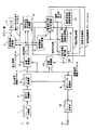
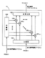
図1は本発明の実施の形態を示すブロック図である。図1と関連技術例である図36とは、強調音声振幅スペクトル補正部18を除いて同一である。以下、これらの相違点を中心に詳細な動作を説明する。
FIG. 1 is a block diagram showing an embodiment of the present invention. FIG. 1 and FIG. 36 which is a related art example are the same except for the emphasized speech amplitude
強調音声振幅スペクトル補正部18には、フーリエ変換部3から劣化音声振幅スペクトル、推定雑音計算部5から推定雑音パワースペクトル、多重乗算部16から強調音声振幅スペクトル、そして抑圧係数補正部15から補正抑圧係数がそれぞれ供給されている。強調音声振幅スペクトル補正部18は、これらの劣化音声振幅スペクトル、推定雑音パワースペクトル、強調音声振幅スペクトル、補正抑圧係数を用いて強調音声振幅スペクトルを補正し、逆フーリエ変換部9へ伝達する。強調音声振幅スペクトル補正部18の構成と動作の詳細な説明は、図2を参照しながら行う。
The enhanced speech amplitude
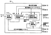
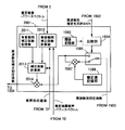
図2は強調音声振幅スペクトル補正部18の構成を示すブロック図である。強調音声振幅スペクトル補正部18は、多重乗算部170、173、音声存在確率計算部171、後抑圧係数計算部182を有する。多重乗算部170は、図1の多重乗算部16から供給される強調音声振幅スペクトルを用いて、強調音声パワースペクトルを計算し、音声存在確率計算部171へ伝達する。音声存在確率計算部171は、多重乗算部170及び図1の推定雑音計算部5から供給される強調音声パワースペクトル及び推定雑音パワースペクトルを用いて、音声存在確率を計算し、後抑圧係数計算部182に伝達する。音声存在確率計算部に供給されている強調音声パワースペクトルと推定雑音パワースペクトルは、共に劣化音声振幅スペクトルから計算されている。従って、音声存在確率は、本質的には劣化音声パワースペクトルを基に計算されていると言える。
FIG. 2 is a block diagram showing the configuration of the enhanced speech amplitude
後抑圧係数計算部182は、音声存在確率計算部171から供給された音声存在確率と、図1の抑圧係数補正部15から供給された補正抑圧係数と、図1の推定雑音計算部5から供給された推定雑音と、図1の抑圧係数補正部15から供給された補正抑圧係数を用いて、後抑圧係数を計算し、多重乗算部173に伝達する。多重乗算部173は、図1のフーリエ変換部から供給された劣化音声振幅スペクトルを、後抑圧係数計算部172から供給された後抑圧係数で重みづけすることによって補正強調音声振幅スペクトルを求め、図1の逆フーリエ変換部9に伝達する。多重乗算部170、173の構成は、図37を用いて説明した多重乗算部13に等しいので、詳細な説明は省略する。
The
音声存在確率計算部171及び後抑圧係数計算部182の構成と動作の詳細な説明は、図3及び図5を参照しながら行う。
Detailed configuration and operation of the speech existence
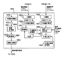
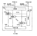
図3は音声存在確率計算部171の構成を示すブロック図である。音声存在確率計算部171は、分離部1700、1708、平均値計算部1701、1709、対数計算部1702、1710、乗算部1703、1711、平滑化係数記憶部1704、1706、平滑化部1705、1707、関数値計算部1712、1713、平均指標計算部1714、瞬時指標計算部1715、加算部1716を有する。
FIG. 3 is a block diagram showing the configuration of the speech existence
分離部1700は、図2の多重乗算部170から供給される強調音声パワースペクトルを周波数別強調音声パワースペクトルに分離し、平均値計算部1701へ出力する。平均値計算部1701は、強調音声パワースペクトル|Xn(k)|2バーのk=0からK−1に対する総和をKで除算し、計算結果を対数計算部1702へ伝達する。対数計算部1702は、平均値計算部1701から入力された平均値の対数を計算し、乗算器1703へ伝達する。乗算器1703は、供給された対数値を定数倍して、強調音声パワーPEnを求め、平滑化部1705、1707へ供給する。すなわち、第nフレームの強調音声パワーPEnは、
で与えられる。 Given in.
一方、分離部1708は、図1の雑音推定計算部5から供給された推定雑音パワースペクトルを周波数別推定雑音パワースペクトルに分離し、平均値計算部1709へ出力する。平均値計算部1709は、周波数別推定雑音パワースペクトルλn(k)のk=0からK−1に対する総和をKで除算し、計算結果を対数計算部1710へ伝達する。対数計算部1710は、平均値計算部1709から供給された平均値の対数を計算し、乗算器1711へ伝達する。乗算器1711は、供給された対数値を定数倍して、推定雑音パワーPNnを求め、関数値計算部1712、1713へ供給する。すなわち、第nフレームの推定雑音パワーPNnは、
で与えられる。 Given in.
入力信号に音声がどの程度含まれているかを表す指標は、推定雑音パワーPNnと強調音声パワーPEnの相対関係をもとに計算される。強調音声パワーPEnが推定雑音パワーPNnよりも大きければ、指標は音声の存在確率が高いことを示す。一般的に、推定雑音パワーPNnと強調音声パワーPEnは非定常信号であるため、音声区間において推定雑音パワーPNnが強調音声パワーPEnよりも大きくなる場合が発生する。逆に、雑音区間でも推定雑音パワーPNnが強調音声パワーPEnよりも大きくなることがある。従って、それぞれのパワーを補正せずに指標計算に用いると、誤った音声存在確率が得られる可能性がある。このため、音声存在確率計算の精度を向上するには、推定雑音パワーPNnと強調音声パワーPEnを適切に補正することが望ましい。また、複数の補正方法を導入し、複数の指標をもとに音声存在確率を計算すれば、精度は更に向上する。 Index indicating it contains what extent audio input signal is calculated based on the relative relationship between the enhanced speech power PE n and the estimated noise power PN n. If the emphasized speech power PE n is larger than the estimated noise power PN n , the index indicates that the presence probability of speech is high. In general, the estimated noise power PN n and the emphasized speech power PE n are non-stationary signals, and therefore the estimated noise power PN n may be larger than the enhanced speech power PE n in the speech interval. On the contrary, the estimated noise power PN n may be larger than the emphasized speech power PE n even in the noise interval. Therefore, if the respective powers are used for index calculation without correction, there is a possibility that an erroneous speech existence probability is obtained. For this reason, in order to improve the accuracy of the speech existence probability calculation, it is desirable to appropriately correct the estimated noise power PN n and the emphasized speech power PE n . Moreover, if a plurality of correction methods are introduced and the speech existence probability is calculated based on a plurality of indices, the accuracy is further improved.
本実施例では、強調音声パワーPEnは平滑化部1715と1716において平滑化処理を用いて、推定雑音パワーPNnは関数値計算部1712と1713において適切な関数を用いて、指標計算に適した値に補正される。指標としては、分析区間長がそれぞれ異なる瞬時指標と平均指標の二種類が計算される。
In this embodiment, the enhanced speech power PE n is suitable for index calculation using smoothing processing in the smoothing
平滑化部1705は、平滑化係数記憶部1704から供給された平滑化係数を用いて、乗算器1703から供給された強調音声パワーPEnを時間方向に平滑化し、第一の平滑強調音声パワーを瞬時指標計算部1715へ供給する。平滑化部1707も同様に、平滑化係数記憶部1706から供給された平滑化係数を用いて、乗算器1703から供給された強調音声パワーPEnを時間方向に平滑化し、第二の平滑強調音声パワーを平均指標計算部1714へ供給する。基本的に、平滑化係数記憶部1704に記憶されている係数の方が、平滑化係数記憶部1706の係数よりも小さくなるように設定される。これは、平滑化係数の値が小さい程、平滑化部の時間方向平滑化効果が小さくなり、瞬時指標の計算に適しているためである。
The
関数値計算部1713は、乗算器1711から供給された推定雑音パワーPNnから第一の関数値を計算し、瞬時指標計算部1715へ供給する。関数値計算部1712も同様に、乗算器1711から供給された推定雑音パワーPNnから第二の関数値を計算し、平均指標計算部1714へ供給する。関数値の計算には、ダイナミックレンジの圧縮や拡大を行うために線形又は非線形関数や、分散を低減するために平滑化が用いられる。ダイナミックレンジの圧縮や拡大、分散の低減により、推定雑音パワーPNnの非定常性に起因する指標計算の精度劣化を低減できる。また、演算量を低減するために、関数値計算を省略し、推定雑音パワーPNnをそのまま指標計算に利用することも可能である。関数値計算部1712と1713では、例えば次のような関数が利用される。
但し、PNnハットは関数値、afcとbfcは実数である。 However, PN n hat is a function value, and a fc and b fc are real numbers.
瞬時指標計算部1715は、平滑化部1705から供給された第一の平滑強調音声パワーと、関数値計算部1713から供給された第一の関数値を用いて、瞬時指標を計算し、加算部1716へ供給する。平均指標計算部1714は、平滑化部1707から供給された第二の平滑強調音声パワーと、関数値計算部1712から供給された第二の関数値を用いて、平均指標を計算し、加算部1716へ供給する。指標の計算には、強調音声パワーPEnと推定雑音パワーPNnの比を計算し、その比に応じて数値を大きくする方法が利用される。具体例としては、次のような計算方法が挙げられる。
但し、IDXnは指標、PEnバーは平滑強調音声パワー、PNnハットは関数値である。また、θidx、aidxとbidxは実数で、aidxはbidx以上の値を有する。 However, IDX n is an index, PE n bar is a smooth emphasis voice power, and PN n hat is a function value. Θ idx , a idx and b idx are real numbers, and a idx has a value equal to or greater than b idx .
比を計算するときに分母に定数を加えると、分母の値が定数よりも小さくならないので、比を計算する際に発散を防止できる。この他にも、強調音声パワーPEnと推定雑音パワーPNnの差や、差を強調音声パワーPEnで正規化した値を用いて計算することもできるが、詳細は省略する。 If a constant is added to the denominator when calculating the ratio, the value of the denominator does not become smaller than the constant, so that divergence can be prevented when calculating the ratio. In addition to this, the difference between the enhanced speech power PE n and the estimated noise power PN n and a value obtained by normalizing the difference with the enhanced speech power PE n can be calculated, but details are omitted.
加算部1716は、平均指標計算部1714及び瞬時指標計算部1715から供給された平均指標及び瞬時指標の和を計算し、音声存在確率として図2の後抑圧係数計算部172へ伝達する。音声存在確率の計算には、加算以外にも、重みつき加算や乗算を用いることが可能である。音声存在確率の精度を改善するために、分析区間が異なる3種類以上の指標を計算しても良い。また、1種類の指標だけを利用し、計算を簡略化することも可能である。
The
平滑化部1705の構成と動作の詳細な説明は、図4を用いて行う。
A detailed description of the configuration and operation of the
図4は、図3の平滑化部1705の構成を示すブロック図である。平滑化部1705は、定数乗算器1741、乗算器1743、1744、加算器1742、1745、遅延器1746を有する。図3の乗算器1703から強調音声パワーPEnが、図3の平滑化係数記憶部1704から平滑化係数が、それぞれ入力として供給される。値δを有する平滑化係数は、定数乗算器1741と乗算器1744に伝達される。定数乗算器1741は、入力信号を−1倍して−δとし、これを加算器1742に伝達する。加算器1742のもう一方の入力としては1が供給されており、加算器1742の出力は両者の和である1−δとなる。1−δは乗算器1743に供給されて、もう一方の入力である強調音声パワーPEnと乗算され、積である(1−δ)PEnが加算器1745に伝達される。
FIG. 4 is a block diagram showing a configuration of the
一方、乗算器1744では、平滑化係数として供給されたδと遅延器1746から供給された1フレーム前の平滑化強調音声パワーPEn−1バーが乗算され、積であるδPEn−1バーが加算器1745に伝達される。加算器1745は、(1−δ)PEnとδPEn−1バーの和を遅延器1746と図3の瞬時指標計算部1715に、平滑化強調音声パワーPEnバーとして、出力する。以上の計算は、式(19)によって表すことができる。
平滑化部1707の構成は、平滑化部1705と同じである。但し、平滑化部1707は、平滑化係数記憶部1706から供給される平滑化係数を用いて、平滑化強調音声パワーを計算する。また、平滑化部1705と1707では、式(19)の他に、移動平均を利用することも可能である。
The configuration of the
図5は、図2の後抑圧係数計算部182の構成を示すブロック図である。後抑圧係数計算部182は、分離部1722、周波数別後抑圧係数計算部18210〜1821K−1、多重化部1723を有する。分離部1722は、図1の抑圧係数補正部5から供給された補正抑圧係数を周波数別補正抑圧係数に分離し、周波数別後抑圧係数計算部18210〜1821K−1に伝達する。周波数別後抑圧係数計算部18210〜1821K−1は、図2の音声存在確率計算部171、図1の多重乗算部16及び推定雑音計算部5からそれぞれ供給される音声存在確率、強調音声振幅スペクトル、推定雑音パワースペクトル、及び分離部1722から供給される周波数別補正抑圧係数を用いて、周波数別後抑圧係数を計算し、多重化部1723に伝達する。
FIG. 5 is a block diagram showing the configuration of the
周波数別後抑圧係数計算部18210〜1821K−1の構成と動作の詳細な説明は、図6を参照しながら行う。
A detailed description of the configuration and operation of the frequency-specific post-frequency suppression
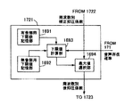
図6は、図5の周波数別後抑圧係数計算部18210〜1821K−1の構成を示すブロック図である。周波数別後抑圧係数計算部1821は、有音部用係数記憶部1831、無音部用係数計算部1832、係数計算部1833、乗算器1834を有する。周波数別後抑圧係数計算部1821は、音声存在確率に応じて、周波数別後抑圧係数を計算する。音声存在確率が低ければ、無音部用係数の寄与率が高い係数を用いて、周波数別後抑圧係数の値を小さくする。このため、雑音区間での残留雑音を更に低減できる。逆に、音声存在確率が高い場合には、有音部用係数の寄与率が高い係数を用いて、周波数別後抑圧係数が周波数別補正抑圧係数と同等の値になるように補正する。また、周波数別後抑圧係数が周波数別補正抑圧係数よりも少し大きくなるように補正しても良い。以上から、音声存在確率が高い場合には、音声の過剰抑圧を防止できる。本実施例では、係数は各周波数毎に計算しているが、全帯域で共通の係数を求め、その係数を周波数別補正抑圧係数に適用すれば、係数の計算に必要な演算量を低減できる。
FIG. 6 is a block diagram illustrating a configuration of the frequency-specific post-frequency suppression
係数計算部1833は、有音部用係数記憶部1831と無音部用係数計算部1832からそれぞれ出力される有音部用係数と無音部用係数、及び図2の音声存在確率計算部171から供給される音声存在確率をもとに、係数を計算する。
The
音声存在確率をp、有音部用係数をFV、無音部用係数をFUとした場合に、係数計算部1833から出力される係数Fは、式(20)で与えられる。
係数の計算では、音声存在確率が大きければ、係数計算部1833の出力値に対する有音部用係数の寄与率を大きくする。式(20)の計算方法では、音声存在確率をそのまま寄与率として利用している。
In the coefficient calculation, if the speech existence probability is large, the contribution ratio of the sound part coefficient to the output value of the
また、式(21)に示すように、適当な関数FSFC、GSFCを用いて有音部用と無音部用の係数を補正してから、音声存在確率を寄与率として利用することも可能である。
この他にも、音声存在確率が予め定められた値以上の場合は、有音部用係数を係数計算部1833から出力することもできる。そして、乗算器1834は、図5の分離部1722から供給される周波数別補正抑圧係数と、係数計算部1833から供給される係数の積を計算し、周波数別後抑圧係数として図5の多重化部1723に伝達する。
In addition to this, when the voice existence probability is equal to or higher than a predetermined value, the coefficient for sound part can be output from the
無音部用係数計算部1832は、図2の音声存在確率計算部171、図1の多重乗算部16及び推定雑音計算部1からそれぞれ供給される音声存在確率、強調音声振幅スペクトル、推定雑音パワースペクトルを用いて、無音部用係数を求め、係数計算部1833へ供給する。雑音区間の残留雑音を低減するため、有音部用係数よりも小さな値を出力するように無音部用係数計算部1832を設計する。
The silent part
無音部用係数計算部1832の構成と動作の詳細な説明は、図7を用いて行う。
A detailed description of the configuration and operation of the silent part
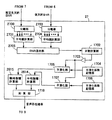
図7は、図6の無音部用係数計算部1832の構成を示すブロック図である。無音部用係数計算部1832は、分離部1850、1855、平均値計算部1851、1856、音声パワー混合部1852、平滑化部1853、平滑化係数記憶部1854、平滑信号記憶部1858、除算部1857、1862、対数計算部1859、定数乗算部1860、係数計算部1861、指数計算部1863を有する。
FIG. 7 is a block diagram showing the configuration of the silent part
分離部1850は、図1の多重乗算部16から供給される強調音声パワースペクトルを周波数別強調音声パワースペクトルに分離し、平均値計算部1851へ伝達する。平均値計算部1851は、周波数別強調音声パワースペクトル|Xn(k)|2バーのk=0からK−1に対する総和をKで除算し、強調音声パワーとして音声パワー混合部1852へ伝達する。音声パワー混合部1852は、平均値計算部1851から供給される強調音声パワーと、平滑信号記憶部1858から供給される1フレーム前の平滑強調音声パワーを、図2の音声存在確率計算部171から供給される音声存在確率に応じて混合し、混合した信号を平滑化部1853へ伝達する。混合の際、音声存在確率が高ければ、平均電力計算部1851から供給される強調音声平均パワーの比率を高くし、低ければ、平滑信号記憶部1858から供給される平滑強調音声パワーの比率を高くする。
Separating
平滑化部1853は、平滑化係数記憶部1854から供給される平滑化係数に応じて、音声パワー混合部1852から供給された混合信号を平滑化し、平滑強調音声パワーとして平滑信号記憶部1858と除算部1857に伝達する。音声パワー混合部の機能から明らかなように、音声存在確率が低い区間では、平滑化部1853は、1フレーム前の平滑強調音声パワーが多く含まれた信号を用いて、平滑強調音声パワーを計算する。従って、平滑強調音声パワーは殆ど更新されない。このため、平滑部1853からは、雑音区間においても、音声区間で計算された強調音声パワーが常に出力される。一方、音声存在確率が高い区間では、平滑化部1853は、強調音声平均パワーが多く含まれた信号を用いて、平滑強調音声パワーを計算する。
The
音声パワー混合部1852で利用されている音声存在確率は、図2の音声存在確率計算部171から供給されており、強調音声パワースペクトルと推定雑音パワースペクトルを基に計算されている。無音部用係数計算部1832にも、強調音声パワースペクトルと推定雑音パワースペクトルが入力されているので、音声パワー混合部1852で利用する音声存在確率を無音部用係数計算部1832の内部でも計算することが可能である。
The voice presence probability used in the voice
また、図2の音声存在確率計算部171の場合と同様に、強調音声パワースペクトルと推定雑音パワースペクトルは、劣化音声振幅スペクトルをもとに計算されているので、音声パワー混合部1852で利用されている音声存在確率は、本質的には劣化音声振幅スペクトルから求められているといえる。
Further, as in the case of the speech existence
一方、分離部1855は、図1の推定雑音計算部5から供給された推定雑音パワースペクトルを周波数別推定雑音パワースペクトルに分離し、平均値計算部1856へ出力する。平均値計算部1856は、周波数別推定雑音パワースペクトルλn(k)のk=0からK−1に対する総和をKで除算し、計算結果を推定雑音平均パワーとして除算部1857へ伝達する。除算部1857は、平滑化部1853から供給される強調音声平均パワーを、平均値計算部1856から供給される推定雑音平均パワーで除算し、除算結果を対数計算部1859へ伝達する。対数計算部1859は、除算部1857から供給された除算結果の対数を計算し、対数値を定数乗算部1860へ伝達する。
On the other hand, the
この定数乗算部1860は、対数計算部1859から供給された対数値を定数倍して、演算結果を係数計算部1861に伝達する。係数計算部1861は、定数乗算部1860の出力から係数を求め、除算部1862へ伝達する。除算部1862のもう一方の入力としては10が供給されているので、除算部1862は、係数計算部1861から供給された係数を10で除算し、除算結果を指数計算部1863へ伝達する。指数部計算部1863は、除算部1862の出力の指数を計算し、演算結果を無音部用係数として図6の係数計算部1833へ伝達する。
The
除算部1857の演算結果は、強調音声平均パワーと推定雑音パワーの比、すなわちSNRに相当する。従って、係数計算部1861は、SNRをもとに無音部の抑圧度を計算していることになる。SNRを計算する目的は、音声存在確率計算部171で求めた音声存在確率の信頼度を、係数の計算に反映することである。SNRが高い場合、すなわち音声存在確率の信頼度が高い場合には、音声を誤って抑圧する可能性が小さいので、係数を小さくし、抑圧度を増加させる。一方、音声存在確率の信頼度が低い場合には、音声を誤って抑圧することを防ぐため、係数を大きくし、抑圧度を減少させる。SNRから係数を求めることが重要なので、計算を簡略化するために、対数計算部1859と指数計算部1863のどちらか一方、もしくは両方を省略することが可能である。
The calculation result of the
また、予め適切に設定した定数を推定雑音平均パワーに加算してから除算を行えば、除算結果の発散を防ぐことができる。除算ではなく、除算の近似演算を利用しても、発散を防止できる。 Further, if division is performed after adding a constant set appropriately in advance to the estimated noise average power, divergence of the division result can be prevented. Divergence can also be prevented by using an approximate operation of division instead of division.
本実施例では、強調音声平均パワーと推定雑音パワーを計算する際に、全帯域のパワースペクトルの平均値を用いたが、適当な帯域幅を持ったサブバンド毎に計算したパワースペクトルの平均値を用いる方法も有効である。各帯域毎に平均値を計算するので、全帯域の平均値を用いた場合よりも、各帯域で正確なSNRを計算することが可能になる。 In this embodiment, when calculating the emphasized speech average power and the estimated noise power, the average value of the power spectrum of the entire band is used. However, the average value of the power spectrum calculated for each subband having an appropriate bandwidth. The method using is also effective. Since the average value is calculated for each band, it is possible to calculate an accurate SNR in each band, compared to the case where the average value of all bands is used.
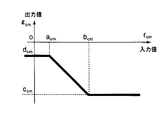
図8に、図7の係数計算部1861で係数を計算する際に用いる非線形関数の例を示す。fcmを入力値としたとき、図8に示される非線形関数の出力値gcmは、式(22)で与えられる。
但し、acm,bcm,ccm,dcmは正の実数である。 However, a cm , b cm , c cm , and d cm are positive real numbers.
fcmが大きくなればgcmが小さくなることが、式(22)の非線形関数に求められる条件である。式(22)の他にも、この条件を満たすような線形関数や高次多項式、重みつき加算を含む任意の関数を用いることができる。 The condition required for the nonlinear function of Equation (22) is that g cm decreases as f cm increases. In addition to Expression (22), a linear function that satisfies this condition, a high-order polynomial, and an arbitrary function including weighted addition can be used.
図9は本発明の第2の実施の形態を示すブロック図である。図9と第1の実施例である図1とは、強調音声振幅スペクトル補正部28を除いて同一である。強調音声振幅スペクトル補正部28の構成と動作の詳細な説明は、図10を参照しながら行う。
FIG. 9 is a block diagram showing a second embodiment of the present invention. FIG. 9 and FIG. 1 as the first embodiment are the same except for the enhanced speech amplitude
図10は強調音声振幅スペクトル補正部28の構成を示すブロック図である。図2に示した強調音声振幅スペクトル補正部18とは、後抑圧係数計算部182が後抑圧係数計算部282に置換されていることを除いて同一である。後抑圧係数計算部282の構成と動作の詳細な説明は、図11を参照しながら行う。
FIG. 10 is a block diagram showing the configuration of the enhanced speech amplitude
図11は後抑圧係数計算部282の構成を示すブロック図である。図5に示した後抑圧係数計算部182とは、周波数別後抑圧係数計算部18210〜1821K−1が周波数別後抑圧係数計算部28210〜2821K−1に置換されていることを除いて同一である。周波数別後抑圧係数計算部28210〜2821K−1の構成と動作の詳細な説明は、図12を参照しながら行う。
FIG. 11 is a block diagram showing the configuration of the
図12は、図11の周波数別後抑圧係数計算部28210〜2821K−1の構成を示すブロック図である。図6に示した周波数別後抑圧係数計算部1821とは、有音部用係数記憶部1831が有音部用係数計算部2831に置換されていることを除いて同一である。無音部用係数だけでなく、有音部用係数も計算するので、図6の周波数別後抑圧係数計算部よりも有音部で高音質を達成できる。
FIG. 12 is a block diagram illustrating the configuration of the frequency-specific post-frequency suppression
有音部用係数計算部2831は、図9の多重乗算部16及び推定雑音計算部5からそれぞれ供給される強調音声パワースペクトルと推定雑音パワースペクトルを用いて、有音部用係数を求め、係数計算部1833へ供給する。推定雑音パワーが強調音声パワーよりも大きい場合、又は両パワーの大きさが同等の場合には、有音部用係数計算部2831は、推定雑音と強調音声のパワー比に応じて、1.0以上の値を出力する。これは、補正抑圧係数が適切な値よりも小さくなっている可能性があるので、音声区間で過剰抑圧となることを防ぐために行う。一方、推定雑音が強調音声よりも小さい場合には、音声区間で過剰抑圧が発生する可能性は低い。そこで、推定雑音と強調音声のパワー比とは無関係に、1.0以上の適切な定数値を出力する。
The sound part
図13は本発明の第3の実施の形態を示すブロック図である。図13と第1の実施例である図1とは、強調音声振幅スペクトル補正部17を除いて同一である。後述するように、強調音声振幅スペクトル補正部17と18の違いは、後抑圧係数の計算を行う際に、強調音声振幅スペクトル補正部17が推定雑音パワースペクトルと強調音声パワースペクトルを利用しないところである。強調音声振幅スペクトル補正部17の構成と動作の詳細な説明は、図14を参照しながら行う。
FIG. 13 is a block diagram showing a third embodiment of the present invention. FIG. 13 and FIG. 1 as the first embodiment are the same except for the emphasized speech amplitude
図14は強調音声振幅スペクトル補正部17の構成を示すブロック図である。図2に示した強調音声振幅スペクトル補正部18とは、後抑圧係数計算部182が後抑圧係数計算部172に置換されていることを除いて同一である。以下、この相違点を中心に詳細な動作を説明する。
FIG. 14 is a block diagram showing the configuration of the enhanced speech amplitude
後抑圧係数計算部172は、音声存在確率計算部171から供給された音声存在確率と、図13の抑圧係数補正部15から供給された補正抑圧係数を用いて、後抑圧係数を計算し、多重乗算部173に伝達する。後抑圧係数計算部172の構成と動作の詳細な説明は、図15を用いて行う。
The
図15は後抑圧係数計算部172の構成を示すブロック図である。図5に示した後抑圧係数計算部182とは、周波数別後抑圧係数計算部18210〜1821K−1が周波数別後抑圧係数計算部17210〜1721K−1に置換されていることを除いて同一である。以下、この相違点を中心に詳細な動作を説明する。
FIG. 15 is a block diagram illustrating a configuration of the post-suppression
周波数別後抑圧係数計算部17210〜1721K−1は、分離部1722から供給される周波数別補正抑圧係数と、図14の音声存在確率計算部171から供給される音声存在確率を用いて、周波数別後抑圧係数を計算し、多重化部1723に伝達する。周波数別後抑圧係数計算部17210〜1721K−1の構成と動作の詳細な説明は、図16を用いて行う。
The frequency-specific post-frequency suppression
図16は、図15の周波数別後抑圧係数計算部17210〜1721K−1の構成を示すブロック図である。周波数別後抑圧係数計算部1721は、有音部用下限値記憶部1691、無音部用下限値記憶部1692、下限値計算部1693、最大値選択部1694を有する。下限値計算部1693は、有音部用下限値記憶部1691から供給される有音部用下限値と、無音部用下限値記憶部1692から供給される無音部用下限値をもとに、図14の音声存在確率計算部171から供給される音声存在確率に応じた下限値を計算し、最大値選択部1694へ伝達する。音声歪みを防止するため、有音部用下限値には、無音部用下限値よりも大きな値が設定される。下限値の計算では、音声存在確率が大きければ、下限値計算部1693の出力値に対する有音部用下限値の寄与率を大きくする。寄与率の設定には、式(20)や式(21)に示される方法を同様に用いることが可能である。
FIG. 16 is a block diagram illustrating a configuration of the frequency-specific post-frequency suppression
最大値選択部1694は、図15の分離部1722から供給される周波数別補正抑圧係数と、下限値計算部1693から供給される下限値とを比較し、大きい方の値を図15の多重化部1723へ伝達する。値が同じ場合まで考慮すると、後抑圧係数は下限値計算部 1693 が供給する下限値以上の値になる。従って、抑圧係数は音声存在確率に応じて設定された下限値以上の値になる。音声存在確率が高ければ、下限値は大きくなるので、音声区間において過剰抑圧がもたらす音声歪みを防止できる。一方、音声存在確率が低ければ、下限値は小さくなるので、雑音区間において十分な抑圧度を得ることができる。
The maximum
図17は本発明の第4の実施の形態を示すブロック図である。図17と第一の実施例である図1とは、強調音声振幅スペクトル補正部29を除いて同一である。強調音声振幅スペクトル補正部29の構成と動作の詳細な説明は、図18を参照しながら行う。
FIG. 17 is a block diagram showing a fourth embodiment of the present invention. FIG. 17 and FIG. 1 as the first embodiment are the same except for the enhanced speech amplitude
図18は強調音声振幅スペクトル補正部29の構成を示すブロック図である。図2に示した強調音声振幅スペクトル補正部18とは、後抑圧係数計算部182が後抑圧係数計算部292に置換されていることを除いて同一である。後抑圧係数計算部292の構成と動作の詳細な説明は、図19を参照しながら行う。
FIG. 18 is a block diagram showing the configuration of the enhanced speech amplitude
図19は後抑圧係数計算部292の構成を示すブロック図である。図5に示した後抑圧係数計算部182とは、周波数別後抑圧係数計算部18210〜1821K−1が周波数別後抑圧係数計算部29210〜2921K−1に置換されていることを除いて同一である。周波数別後抑圧係数計算部29210〜2921K−1の構成と動作の詳細な説明は、図20を参照しながら行う。
FIG. 19 is a block diagram showing the configuration of the
図20は、図19の周波数別後抑圧係数計算部29210〜2921K−1の構成を示すブロック図である。図16に示した周波数別後抑圧係数計算部1721とは、有音部用下限値記憶部1691が有音部用下限値計算部2691に置換されていること、無音部用下限値記憶部1692が無音部用下限値計算部2692を除いて同一である。強調音声パワースペクトルと推定雑音パワースペクトルを基に、有音部用及び無音部用下限値を計算するので、図16の周波数別後抑圧係数計算部よりも、無音部で残留雑音を、有音部で音声歪みを低減できる。
FIG. 20 is a block diagram illustrating a configuration of frequency-specific post-frequency suppression
有音部用下限値計算部2691と無音部用下限値計算部2692は、図17の多重乗算部16及び推定雑音計算部1からそれぞれ供給される強調音声パワースペクトルと推定雑音パワースペクトルを用いて、有音部用下限値と無音部用下限値をそれぞれ求め、下限値計算部1693へ供給する。有音部用下限値計算部2691と無音部用下限値計算部2692は、推定雑音と強調音声のパワー比に応じて、それぞれの下限値を計算し、下限値計算部1693へ伝達する。基本的には、推定雑音パワーが強調音声パワーよりも大きくなる、すなわちSNRが低くなれば、音声歪みを防止する目的で有音部用下限値を大きくする。
The voiced lower limit
無音部での残留雑音量を小さく、有音部での過剰抑圧を防止するために、無音部用下限値を有音部用下限値以下の値にする。但し、SNRが低い場合には、有音部用下限値と無音部用下限値の差が大きくならないように制御する。下限値の差が大きすぎると、有音部と無音部の残留雑音量の差が大きくなり、結果的に音声区間で音声ひずみが発生しているように知覚されてしまう。逆に、SNRが高ければ、有音部の残留雑音は、音声成分にマスクされて知覚されにくくなる。従って、SNRが低いときのように、有音部と無音部の残留雑音量の差は、音声区間での音声ひずみ要因に殆どならない。 In order to reduce the amount of residual noise in the silent part and prevent excessive suppression in the voiced part, the lower limit value for the silent part is set to a value equal to or lower than the lower limit value for the voiced part. However, when the SNR is low, control is performed so that the difference between the lower limit value for the sounded part and the lower limit value for the silent part is not increased. If the difference between the lower limit values is too large, the difference in the amount of residual noise between the sound part and the soundless part becomes large, and as a result, it is perceived that sound distortion occurs in the sound section. On the other hand, if the SNR is high, the residual noise in the sound part is masked by the sound component and becomes difficult to perceive. Therefore, as in the case where the SNR is low, the difference in the amount of residual noise between the voiced part and the silent part hardly causes a voice distortion factor in the voice section.
そこで、SNRが高い場合には、無音部用下限値と有音部用下限値の差を大きくして、無音部での残留雑音を十分に低減する。以上より、無音部用下限値は、有音部用下限値に依存した値に設定される。従って、基本的には、有音部下限値の場合と同様に、SNRが低くなれば、無音部用下限値も大きくする。推定雑音パワースペクトルと強調音声パワースペクトルの大きさを比較する場合は、それぞれの平均値や、図11の無音部用係数計算で用いられている除算部1857の出力信号を用いることが好ましい。
Therefore, when the SNR is high, the difference between the lower limit value for the silent part and the lower limit value for the voiced part is increased to sufficiently reduce the residual noise in the silent part. From the above, the silent part lower limit value is set to a value depending on the voiced part lower limit value. Therefore, basically, as in the case of the lower limit value of the sound part, the lower limit value for the silent part is increased as the SNR decreases. When comparing the magnitudes of the estimated noise power spectrum and the emphasized speech power spectrum, it is preferable to use the respective average values or the output signal of the
図21は本発明の第5の実施の形態を示すブロック図である。図21と関連技術例のブロック図である図36とは、推定先天的SNR計算部7及び抑圧係数補正部15が、推定先天的SNR計算部71及び抑圧係数補正部19にそれぞれ置換されていることを除いて同一である。以下、これらの相違点を中心に詳細な動作を説明する。
FIG. 21 is a block diagram showing a fifth embodiment of the present invention. FIG. 21 and FIG. 36 which is a block diagram of the related art example, the estimated innate
推定先天的SNR計算部71には、多重乗算部13から劣化音声パワースペクトル、推定雑音計算部5から推定雑音パワースペクトル、周波数別SNR計算部6から後天的SNR、抑圧係数補正部19から補正抑圧係数が供給される。推定先天的SNR計算部71は、劣化音声パワースペクトル、推定雑音パワースペクトル、後天的SNR及び補正抑圧係数を用いて、推定先天的SNRと音声存在確率を求める。そして、音声存在確率を抑圧係数補正部19に、推定先天的SNRを雑音抑圧係数生成部8と抑圧係数補正部19に伝達する。抑圧係数補正部19は、推定先天的SNR計算部71から供給される推定先天的SNRと音声存在確率を用いて、雑音抑圧係数生成部8から供給される抑圧係数を補正し、補正抑圧係数として多重乗算部16と推定先天的SNR計算部71へ伝達する。
The estimated
抑圧係数補正部19及び推定先天的SNR計算部71の構成と動作の詳細な説明は、図22及び図23を参照しながら行う。
A detailed description of the configuration and operation of the suppression
図22は推定先天的SNR計算部71の構成を示すブロック図である。図22と関連技術例のブロック図である図45との相違点は、推定先天的SNR計算部71が遅延器711、712、多重乗算部713、音声存在確率計算部714を有していることである。以下、これらの相違点を中心に詳細な動作を説明する。
FIG. 22 is a block diagram showing the configuration of the estimated innate
遅延器712は、図21の推定雑音計算部5から供給される第nフレームの推定雑音パワースペクトルλn(k)を保存すると同時に、保存してあった第n−1フレームの推定雑音パワースペクトルλn−1(k)を音声存在確率計算部714に供給する。遅延器711は、図21の多重乗算部13から供給される第nフレームの劣化音声パワースペクトル|Yn(k)|2を保存すると同時に、保存してあった第n−1フレームの劣化音声パワースペクトル|Yn−1(k)|2を多重乗算部713に供給する。多重乗算部713は、多重乗算部704から供給されるG2 n−1(k)バーと遅延器711から供給される|Yn−1(k)|2をk=0,1, ..., K−1に対して乗算して、G2 n−1(k)バー|Yn−1(k)|2を求め、演算結果を推定強調音声パワースペクトルとして音声存在確率計算部714へ伝達する。多重乗算部713の出力信号は、第n−1フレームの強調音声パワースペクトルに一致するが、これを第nフレームの強調音声パワースペクトルの推定信号として扱うために、推定強調音声パワースペクトルという名称を用いている。
The
多重乗算部704から供給される抑圧係数は、一フレーム前に得られたものなので、抑圧係数と劣化音声パワースペクトルのフレーム番号を合わせて強調音声パワースペクトルを計算するために、遅延器711が導入されている。更に、音声存在確率の計算に用いる強調音声パワースペクトルと推定雑音パワースペクトルのフレーム番号を合わせるために、遅延器712が導入されている。しかし、数フレームの相違が音声存在確率の計算に与える影響は小さいことから、遅延器711と712のどちらか一方、もしくは両方を省略することが可能である。
Since the suppression coefficient supplied from the
音声存在確率計算部714は、多重乗算部713から供給される推定強調音声パワースペクトルと、遅延器712から供給される推定雑音パワースペクトルを用いて音声存在確率を計算し、図21の抑圧係数補正部19へ伝達する。多重乗算部713の構成は、既に図37を用いて説明した多重乗算部21に等しいので、詳細な説明は省略する。また、音声存在確率計算部714の構成は、図3を用いて説明した音声存在確率計算部171に等しいので、詳細な説明は省略する。
The speech existence
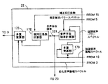
図23は、図21の抑圧係数補正部19の構成を示すブロック図である。図50に示した抑圧係数補正部15とは、周波数別抑圧係数補正部15010〜1501K−1が周波数別抑圧係数補正部19010〜1901K−1に置換されていることを除いて同一である。以下、これらの相違点を中心に詳細な動作を説明する。
FIG. 23 is a block diagram showing a configuration of the suppression
周波数別抑圧係数補正部19010〜1901K−1は、分離部1502から供給される周波数別推定先天的SNRと、図21の推定先天的SNR計算部71から供給される音声存在確率を用いて、分離部1503から供給される周波数別抑圧係数を補正し、周波数別補正抑圧係数として多重化部1504へ伝達する。周波数別抑圧係数補正部19010〜1901K−1の構成と動作の詳細な説明は、図24を用いて行う。
The frequency-specific suppression
図24は、図23の周波数別抑圧係数補正部19010〜1901K−1の構成を示すブロック図である。図24では、図51の周波数別抑圧係数補正部1501における最大値選択部1591及び抑圧係数下限値記憶部1592の代わりに、有音部用下限値記憶部1921、無音部用下限値記憶部1922、下限値計算部1923、及び最大値選択部1924が具備されている。以下、これらの相違点を中心に詳細な動作を説明する。
FIG. 24 is a block diagram illustrating the configuration of the frequency-specific suppression
下限値計算部1923は、有音部用下限値記憶部1921から供給される有音部用下限値と、無音部用下限値記憶部1922から供給される無音部用下限値をもとに、図21の推定先天的SNR計算部71から供給される音声存在確率に応じた下限値を計算し、最大値選択部1924へ伝達する。最大値選択部1924は、スイッチ1595又は乗算器1597の出力値と、下限値計算部1923から供給される下限値とを比較し、大きい方の値を補正抑圧係数として図23の多重化部1504へ伝達する。値が同じ場合まで考慮すると、補正抑圧係数は下限値計算部1923が供給する下限値より以上の値になる。従って、抑圧係数が音声存在確率に応じて設定された下限値以上の値になるので、音声区間において過剰抑圧がもたらす音声歪みを防止できる。下限値計算部1923の構成は、図6を用いて既に説明した下限値計算部1693に等しいので、詳細な説明は省略する。
The lower limit value calculation unit 1923 is based on the lower limit value for a sound part supplied from the lower limit
図25は本発明の第6の実施の形態を示すブロック図である。図25と関連技術例のブロック図である図36とは、推定先天的SNR計算部7及び抑圧係数補正部15が推定先天的SNR計算部72及び抑圧係数補正部20にそれぞれ置換されていることを除いて同一である。以下、これらの相違点を中心に詳細な動作を説明する。
FIG. 25 is a block diagram showing a sixth embodiment of the present invention. FIG. 25 and FIG. 36, which is a block diagram of the related art example, show that the estimated innate
推定先天的SNR計算部72には、多重乗算部13から劣化音声パワースペクトル、推定雑音計算部5から推定雑音パワースペクトル、周波数別SNR計算部6から後天的SNR、抑圧係数補正部20から補正抑圧係数が供給される。推定先天的SNR計算部72は、劣化音声パワースペクトル、推定雑音パワースペクトル、後天的SNR及び補正抑圧係数を用いて、推定先天的SNR、音声存在確率及び推定強調音声パワースペクトルを求める。そして、抑圧係数補正部20に推定先天的SNR、音声存在確率及び推定強調音声パワースペクトルを、雑音抑圧係数生成部8に推定先天的SNRをそれぞれ伝達する。抑圧係数補正部20は、推定先天的SNR計算部72から供給される推定先天的SNR、音声存在確率及び推定強調音声パワースペクトルを用いて、雑音抑圧係数生成部8から供給される抑圧係数を補正し、補正抑圧係数として多重乗算部16と推定先天的SNR計算部72へ伝達する。推定先天的SNR計算部72及び抑圧係数補整正部20の構成と動作の詳細な説明は、図26及び図27を参照しながら行う。
The estimated innate
図26は推定先天的SNR計算部72の構成を示すブロック図である。図22の推定先天的SNR計算部71とは、多重乗算部713が多重乗算部715に置換されていることを除いて同一である。多重乗算部713は音声存在確率計算部714だけに推定強調音声パワースペクトルを供給していたが、多重乗算部715は図25の抑圧係数補正部20にも供給する。多重乗算部715の構成は、図22を用いて既に説明した多重乗算部713に等しいので、詳細な説明は省略する。
FIG. 26 is a block diagram showing a configuration of the estimated innate
図27は抑圧係数補正部20の構成を示すブロック図である。図50の抑圧係数補正部15とは、周波数別抑圧係数補正部15010〜1501K−1が周波数別抑圧係数補正部20010〜2001K−1に置換されていることを除いて同一である。以下、これらの相違点を中心に詳細な動作を説明する。
FIG. 27 is a block diagram illustrating a configuration of the suppression
周波数別抑圧係数補正部20010〜2001K−1には、分離部1502から周波数別推定先天的SNR、図25の推定雑音計算部5から推定雑音パワースペクトル、図25の推定先天的SNR計算部72から音声存在確率と推定強調音声パワースペクトルがそれぞれ供給されている。周波数別推定先天的SNR、推定雑音パワースペクトル、推定強調音声パワースペクトル及び音声存在確率を用いて、分離部1503から供給される周波数別抑圧係数を補正し、周波数別補正抑圧係数として多重化部1504へ伝達する。周波数別抑圧係数補正部20010〜2001K−1の構成と動作の詳細な説明は、図28を用いて行う。
The frequency-specific suppression
図28は、図27の周波数別抑圧係数補正部20010〜2001K−1の構成を示すブロック図である。図28では、図51の周波数別抑圧係数補正部1501における最大値選択部1591及び抑圧係数下限値記憶部1592の代わりに、有音部用補正係数記憶部2011、無音部用補正係数記憶部2012、補正係数計算部2013、及び乗算器2014が具備されている。以下、これらの相違点を中心に詳細な動作を説明する。
FIG. 28 is a block diagram illustrating a configuration of the frequency-specific suppression
無音部用補正係数計算部2012は、図25の推定先天的SNR計算部72から供給される音声存在確率と推定強調音声パワースペクトル、及び図25の推定雑音計算部5から供給される推定雑音パワースペクトルを用いて無音部用補正係数を計算し、補正係数計算部2013へ供給する。補正係数計算部2013は、有音部用補正係数記憶部2011から供給される有音部用補正係数と、無音部用補正係数計算部2012から供給される無音部用補正係数をもとに、図25の推定先天的SNR計算部72から供給される音声存在確率に応じた補正係数を計算し、乗算器2014へ伝達する。乗算器2014は、補正係数計算部2013から供給される補正係数と、スイッチ1595又は乗算器1597の出力値との積を計算し、補正抑圧係数として図27の多重化部1504へ伝達する。音声存在確率に応じて計算された補正係数により抑圧係数が補正されるので、雑音区間において残留雑音を更に抑圧できる。無音部用補正係数計算部2012の構成は、既に図7を用いて説明した無音部用補正係数計算部1832に等しいので、詳細な説明は省略する。また、補正係数計算部2013の構成は、図6を用いて既に説明した補正係数計算部1833に等しいので、詳細な説明は省略する。
The silent part correction
図29は本発明の第7の実施の形態を示すブロック図である。図29と第3の実施例である図13との相違点は、音声非存在確率記憶部21の代わりに遅延器23と加算器24が具備されていること、及び強調音声振幅スペクトル補正部17が強調音声振幅スペクトル補正部22に置換されていることである。以下、これらの相違点を中心に詳細な動作を説明する。
FIG. 29 is a block diagram showing a seventh embodiment of the present invention. The difference between FIG. 29 and FIG. 13 which is the third embodiment is that a
強調音声振幅スペクトル補正部22から出力された音声存在確率は、遅延器23に保存される。遅延器23は、一フレーム前の音声存在確率を加算器24へ伝達する。雑音抑圧係数が生成された後に、音声存在確率が計算されるため、雑音抑圧係数の生成に必要となる音声存在確率の計算には、一フレーム前の音声存在確率を利用する。加算器24は、1から音声存在確率を差し引いた値を計算し、計算結果を音声非存在確率として、雑音抑圧係数生成部へ伝達する。図13の第3の実施例では常に同じ音声非存在確率を用いて雑音抑圧係数の生成を行っていたが、本実施例では強調音声振幅スペクトル補正部で計算した音声存在確率を基に音声非存在確率を計算している。このため、関連技術よりも各入力信号に適した音声非存在確率を、雑音抑圧係数の生成に用いることが可能である。強調音声振幅スペクトル補正部22の構成と動作の詳細な説明は、図30を参照しながら行う。
The speech existence probability output from the enhanced speech amplitude
図30は、図29の強調音声振幅スペクトル補正部22の構成を示すブロック図である。図14の強調音声振幅スペクトル補正部17とは、音声存在確率計算部171が音声存在確率計算部221に置換されていることを除いて同一である。図14の音声存在確率計算部171は、音声存在確率を後抑圧係数172のみに伝達しているが、図30の音声存在確率計算部221は、更に図29の遅延器23にも伝達している。
FIG. 30 is a block diagram illustrating a configuration of the enhanced speech amplitude
図31は、本発明の第8の実施の形態を示すブロック図である。図31と第7の実施例である図29との相違点は、遅延器23の代わりに音声存在確率計算部26が具備されていること、及び強調音声振幅スペクトル補正部22が強調音声振幅スペクトル補正部25に置換されていることである。音声存在確率計算部26は、推定先天的SNR計算部7から出力された推定先天的SNRを用いて、音声存在確率を計算し、加算器24と強調音声振幅スペクトル補正部25へ伝達する。第7の実施例である図29とは異なり、雑音抑圧係数を生成する前に音声存在確率を計算するため、雑音抑圧係数生成部8は、一フレーム前に計算した音声存在確率を基に導出された音声非存在確率を用いる必要が無い。このため、本実施例の雑音抑圧係数生成部8は、第7の実施例の場合よりも正確な音声非存在確率を用いることが可能である。強調音声振幅スペクトル補正部25と音声存在確率計算部26の構成と動作の詳細な説明は、図32及び図33を参照しながら行う。
FIG. 31 is a block diagram showing an eighth embodiment of the present invention. The difference between FIG. 31 and FIG. 29 which is the seventh embodiment is that a speech existence
図32は、図31の強調音声振幅スペクトル補正部25の構成を示すブロック図である。図30の強調音声振幅スペクトル補正部22とは、音声存在確率計算部221と多重乗算部170が削除されていること、及び後抑圧係数計算部172が後抑圧係数252に置換されていることを除いて同一である。後抑圧係数計算部は、図31の音声存在確率計算部26から出力された音声存在確率を基に、図31の抑圧係数補正部15から出力された補正抑圧係数から後抑圧係数を計算し、多重乗算部173へ伝達する。音声非存在確率を強調音声振幅スペクトル補正部の外部で計算している点が、図30の後抑圧係数計算部172と図32の後抑圧係数計算部252との相違点である。
FIG. 32 is a block diagram showing a configuration of the enhanced speech amplitude
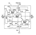
図33は、図31の音声存在確率計算部26の構成を示すブロック図である。図3の音声存在確率計算部171とは、分離部1708、平均値計算部1709、対数計算部1710、乗算器1711、関数値計算部1712、1713が削除されていること、平均指標計算部が1714から2614に、瞬時指標計算部が1715から2615に置換されていること、及び分離部1700への入力が強調音声パワースペクトルから推定先天的SNRに置換されていることを除いて同一である。図3の音声存在確率計算部171と図33の音声存在確率計算部26の共通点は、音声と雑音の比に応じて指標を計算している点である。音声存在確率計算部171は、強調音声パワーと推定雑音パワーの双方を、指標計算に適した値に補正するが、音声存在確率計算部26は推定先天的SNRを補正する。このため、音声存在確率計算部26の方が少ない演算量で実現できる。以下、これらの相違点を中心に詳細な動作を説明する。
FIG. 33 is a block diagram showing the configuration of the speech existence
分離部1700は、図31の推定先天的SNR計算部7から供給される推定先天的SNRを周波数別推定先天的SNRに分離し、平均値計算部1701へ出力する。平均値計算部1701は、周波数別推定先天的SNRξn(k)ハットのk=0からK−1に対する総和をKで除算し、計算結果を対数計算部1702へ伝達する。対数計算部1702は、平均値計算部1701から入力された平均値の対数を計算し、乗算器1703へ伝達する。乗算器1703は、供給された対数値を定数倍して、フルバンド推定先天的SNRΞ(n)を求め、平滑部1705、1707へ供給する。すなわち、第nフレームのフルバンド推定先天的SNRΞ(n)は、次式で与えられる。
平滑化部1705は、平滑化係数記憶部1704から供給された平滑化係数を用いて、乗算器1703から供給されたフルバンド推定先天的SNRΞ(n)を時間方向に平滑化し、第一の平滑先天的SNRとして瞬時指標計算部2615へ供給する。平滑化部1707も同様に、平滑化係数記憶部1706から供給された平滑化係数を用いて、乗算器1703から供給されたフルバンド推定先天的SNRΞ(n)を時間方向に平滑化し、第二の平滑先天的SNRとして平均指標計算部2614へ供給する。図3の音声存在確率計算部171を説明したときに述べたとおり、平滑化係数記憶部1704に記憶されている係数の方が、平滑化係数記憶部1706の係数よりも小さくなるように設定される。
The
瞬時指標計算部2615は、平滑化部1705から供給された第一の平滑先天的SNRを用いて、瞬時指標を計算し、加算部1716へ供給する。平均指標計算部2614は、平滑化部1707から供給された第二の平滑先天的SNRを用いて、平均指標を計算し、加算部1716へ供給する。指標の計算には、平滑先天的SNRに応じて数値を大きくする方法が利用される。具体例としては、次のような計算方法が挙げられる。
但し、IDX2nは指標、Ξ(n)バーは平滑先天的SNRである。また、θidx2、aidx2とbidx2は実数で、aidx2はbidx2以上の値を有する。 Where IDX2 n is an index and Ξ (n) bar is a smooth innate SNR. Also, θ idx2 , a idx2 and b idx2 are real numbers, and a idx2 has a value equal to or greater than b idx2 .
図34は、本発明の第9の実施の形態を示すブロック図である。図34と第8の実施例である図31との相違点は、音声存在確率計算部26が音声存在確率計算部27に置換されていることである。音声存在確率計算部27は、周波数別SNR計算部6から出力された後天的SNRと推定先天的SNR計算部7から出力された推定先天的SNRを用いて、音声存在確率を計算し、加算器24と強調音声振幅スペクトル補正部25へ伝達する。音声存在確率計算部27の構成と動作の詳細な説明は、図35を参照しながら行う。
FIG. 34 is a block diagram showing a ninth embodiment of the present invention. The difference between FIG. 34 and FIG. 31 of the eighth embodiment is that the voice presence
図35は、図34の音声存在確率計算部27の構成を示すブロック図である。図31の音声存在確率計算部26とは、分離部1700が2700に、平均値計算部1701が2701に置換されていること、更に、分離部2703と平均値計算部2704、及びSNR混合部2705が具備されていることを除いて同一である。図31の音声存在確率計算部26との主な相違点は、対数計算部1702へ入力されるSNRの推定精度が改善されている点である。以下、これらの相違点を中心に詳細な動作を説明する。
FIG. 35 is a block diagram showing a configuration of the speech existence
分離部2700は、図34の推定先天的SNR計算部7から供給される推定先天的SNRを周波数別推定先天的SNRに分離し、平均値計算部2701へ出力する。平均値計算部2701は、周波数別推定先天的SNRξn(k)ハットのk=0からK−1に対する総和をKで除算し、計算結果を平均先天的SNRξnバーとしてSNR混合部2705へ伝達する。すなわち、第nフレームの平均先天的SNRξnバーは、次式で与えられる。
一方、分離部2703は、図34の周波数別SNR計算部6から供給される後天的SNRを周波数別後天的SNRに分離し、平均値計算部2704へ出力する。平均値計算部2704は、周波数別後天的SNRγn(k)のk=0からK−1に対する総和をKで除算し、計算結果を平均後天的SNRγnバーとしてSNR混合部2705へ伝達する。すなわち、第nフレームの平均後天的SNRγnバーは、
で与えられる。 Given in.
SNR混合部は、平均値計算部2701から供給される平均先天的SNRξnバーと、平均値計算部2703から供給される平均後天的SNRγnバーを用いて、混合SNRΞmix(n)を計算し、対数計算部1702へ伝達する。混合SNRΞmix(n)の計算には、平均先天的SNRξnバーに応じて数値を大きくする方法が利用される。具体例としては、次のような計算方法が挙げられる。
但し、Fmixは平均先天的SNRξnバーの関数である。 Where F mix is a function of the average innate SNRξ n bar.
Fmixは、0から1までの実数を出力し、ξnバーが大きければ、大きな値を出力する。すなわち、SNRが高い場合には、平均先天的SNRξnバーよりも推定精度が高い平均後天的SNRγnバーを優先的に用いて混合SNRΞmix(n)を計算する。このため、先天的SNRと後天的SNRの両方を用いて求めた混合SNRΞmix(n)の推定精度は、先天的SNRだけを用いて求めたフルバンド推定先天的SNRΞ(n)よりも高くなる。推定精度が高いSNRを用いて音声存在確率を計算することが可能になるため、図34の音声存在確率計算部27は、図31の音声存在確率計算部26よりも高い精度を達成できる。
F mix outputs a real number from 0 to 1, and outputs a large value if ξ n bar is large. That is, when the SNR is high, calculates the average congenital SNRkushi n estimation accuracy than bar higher average acquired SNRganma n bar preferentially used mixed SNRΞ mix (n). Therefore, the estimation accuracy of the mixed SNRS mix (n) obtained using both the innate SNR and the acquired SNR is higher than the full-band estimation innate SNRS (n) obtained using only the innate SNR. . Since it is possible to calculate the speech existence probability using the SNR with high estimation accuracy, the speech presence
これまで説明した全ての実施の形態では、雑音抑圧の方式として、最小平均2乗誤差短時間スペクトル振幅法を仮定してきたが、その他の方法にも適用することができる。このような方法の例として、 非特許文献2に開示されているウィーナーフィルタ法や、非特許文献3に開示されているスペクトル減算法などがあるが、これらの詳細な構成例については説明を省略する。
In all the embodiments described so far, the minimum mean square error short-time spectrum amplitude method has been assumed as a noise suppression method, but it can also be applied to other methods. Examples of such methods include the Wiener filter method disclosed in
1 フレーム分割部
2 窓がけ処理部
3 フーリエ変換部
4,5049 カウンタ
5 推定雑音計算部
6,1402 周波数別SNR計算部
7,71,72 推定先天的SNR計算部
8 雑音抑圧係数生成部
9 逆フーリエ変換部
10 フレーム合成部
11 入力端子
12 出力端子
14 重みつき劣化音声計算部
15 抑圧係数補正部
172,182,252,282,292 後抑圧係数計算部
13,16,170,173,704,705,713,715,1404 多重乗算部
17,18,22,25,28,29 強調音声振幅スペクトル補正部
21 音声非存在確率記憶部
171,221,26,27,714 音声存在確率計算部
1742,1745,708,5046,1716,7092,7094,24 加算器
711,712,1746,23 遅延器
1593,5204,5206 閾値記憶部
1594,5203,5205 比較部
1702,1710,1859 対数計算部
1704,1706,1854 平滑化係数記憶部
1705,1707,1853 平滑化部
1712,1713 関数値計算部
1714,2614 平均指標計算部
1715,2615 瞬時指標計算部
2705 SNR混合部
1852 音声パワー混合部
1858 平滑信号記憶部
1863 指数計算部
70710〜7071K−1 重みつき加算部
706 重み記憶部
503,1304,1424,1475,1504,1723,7014,7075 多重化部
5040〜504K−1 周波数別推定雑音計算部
520 更新判定部
5207 閾値計算部
1595,5044 スイッチ
1857,1862,14210〜1421K−1,5048 除算部
501,502,1302,1303,1422,1423,1495,1502,1503,1700,1708,1722,1850,1855,7013,7072,7074,2700,2703 分離部
1701,1709,1851,1856,2701,2704 平均値計算部
701 多重値域限定処理部
702 後天的SNR記憶部
703 抑圧係数記憶部
707 多重重みつき加算部
1401,5042 推定雑音記憶部
921 瞬時推定SNR
9210〜921K−1 周波数別瞬時推定SNR
922 過去の推定SNR
9220〜922K−1 過去の周波数別推定SNR
924 推定先天的SNR
9240〜924K−1 周波数別推定先天的SNR
1405 多重非線形処理部
14850〜1485K−1,5042 非線形処理部
15010〜1501K−1,19010〜1901K−1,20010〜2001K−1 周波数別抑圧係数補正部
17210〜1721K−1,18210〜1821K−1,28210〜2821K−1,29210〜2921K−1 周波数別後抑圧係数計算部
1591,1694,1924,70120〜7012K−1 最大値選択部
1592 抑圧係数下限値記憶部
1596 修正値記憶部
1691,1921 有音部用下限値記憶部
1692,1922 無音部用下限値記憶部
2691 有音部下限値計算部
2692 無音部用下限値計算部
1693,1923 下限値計算部
1831 有音部用係数記憶部
2831 有音部用係数計算部
1832 無音部用係数計算部
1833,1861 係数計算部
2011 有音部用補正係数記憶部
2012 無音部用補正係数記憶部
2013 補正係数計算部
13010〜1301K−1,1597,1703,1711,1743,1744,1834,2014,7091,7093 乗算器
1741,1860,7095 定数乗算器
5045 シフトレジスタ
5047 最小値選択部
5201 論理和計算部
5041 レジスタ長記憶部
7011 定数記憶部
811 MMSE STSAゲイン関数値計算部
812 一般化尤度比計算部
814 抑圧係数計算部
DESCRIPTION OF SYMBOLS 1 Frame division part 2 Windowing process part 3 Fourier transform part 4,5049 Counter 5 Estimated noise calculation part 6,1402 Frequency-specific SNR calculation part 7,71,72 Estimated innate SNR calculation part 8 Noise suppression coefficient generation part 9 Inverse Fourier Conversion unit 10 Frame synthesis unit 11 Input terminal 12 Output terminal 14 Weighted degraded speech calculation unit 15 Suppression coefficient correction unit 172, 182, 252, 282, 292 Post suppression coefficient calculation unit 13, 16, 170, 173, 704, 705 713, 715, 1404 Multiplexing units 17, 18, 22, 25, 28, 29 Enhanced speech amplitude spectrum correction unit 21 Speech non-existence probability storage units 171, 221, 26, 27, 714 Speech presence probability calculation units 1742, 1745, 708, 5046, 1716, 7092, 7094, 24 Adders 711, 712, 1746, 23 Extender 1593, 5204, 5206 Threshold storage unit 1594, 5203, 5205 Comparison unit 1702, 1710, 1859 Logarithm calculation unit 1704, 1706, 1854 Smoothing coefficient storage unit 1705, 1707, 1853 Smoothing unit 1712, 1713 Function value calculation unit 1714, 2614 Average index calculation unit 1715, 2615 Instantaneous index calculation unit 2705 SNR mixing unit 1852 Audio power mixing unit 1858 Smooth signal storage unit 1863 Exponential calculation unit 7071 0 to 7071 K-1 Weighted addition unit 706 Weight storage units 503, 1304 , 1424,1475,1504,1723,7014,7075 multiplexer 504 0 ~504 K-1 frequency domain estimated noise calculator 520 update determination unit 5207 threshold calculating unit 1595,5044 switches 1857,1862,1421 0 421 K-1, 5048 divider 501,502,1302,1303,1422,1423,1495,1502,1503,1700,1708,1722,1850,1855,7013,7072,7074,2700,2703 separation unit 1701,1709 , 1851, 1856, 2701, 2704 Average value calculation unit 701 Multiple range restriction processing unit 702 Acquired SNR storage unit 703 Suppression coefficient storage unit 707 Multiple weighted addition units 1401, 5042 Estimated noise storage unit 921 Instantaneous estimation SNR
921 0 to 921 K-1 instantaneous estimated SNR by frequency
922 Past estimated SNR
922 0 to 922 K-1 Estimated SNR by frequency in the past
924 Estimated innate SNR
924 0 to 924 K-1 Estimated Innate SNR by Frequency
1405 Multiple nonlinear processing units 1485 0 to 1485 K−1 , 5042
Claims (4)
前記周波数領域信号に基づいて抑圧係数を定め、
前記周波数領域信号に基づいて音声と雑音の相対関係を求め、
前記相対関係に基づいて寄与率を定め、
前記寄与率と、予め定められた、第一仮最小抑圧係数および第二仮最小抑圧係数に基づいて最小抑圧係数を求め、
前記抑圧係数と前記最小抑圧係数とを比較し、
値が大きい方を補正抑圧係数とし、
前記補正抑圧係数を前記周波数領域信号に重みづけすることによって雑音を抑圧する雑音抑圧の方法であって、
前記最小抑圧係数は、
前記寄与率を重みとする、
前記第一仮最小抑圧係数と前記第二仮最小抑圧係数の重み付き和で定まることを特徴とする雑音抑圧の方法。 Convert the input signal to a frequency domain signal,
Determine a suppression coefficient based on the frequency domain signal,
Obtaining the relative relationship between speech and noise based on the frequency domain signal,
A contribution rate is determined based on the relative relationship ,
Obtaining a minimum suppression coefficient based on the contribution rate and a predetermined first temporary minimum suppression coefficient and a second temporary minimum suppression coefficient ;
Comparing the suppression coefficient with the minimum suppression coefficient;
The one with the larger value is the correction suppression coefficient,
A noise suppression method for suppressing noise by weighting the corrected suppression coefficient to the frequency domain signal ,
The minimum suppression coefficient is
Using the contribution rate as a weight,
A noise suppression method characterized by being determined by a weighted sum of the first temporary minimum suppression coefficient and the second temporary minimum suppression coefficient .
前記周波数領域信号に基づいて抑圧係数を定める抑圧係数計算部と、
前記周波数領域信号に基づいて音声と雑音の相対関係を求める相対関係計算部と、
前記相対関係に基づいて寄与率を定め、前記寄与率と、予め定められた、第一仮最小抑圧係数および第二仮最小抑圧係数に基づいて最小抑圧係数を求める最小抑圧係数計算部と、
前記抑圧係数と前記最小抑圧係数とを比較し、値が大きい方を補正抑圧係数とする補正抑圧係数計算部と、
前記補正抑圧係数を前記周波数領域信号に重みづけする重みづけ演算部と、
を含む雑音抑圧の装置であって、
前記最小抑圧係数は、
前記寄与率を重みとする、
前記第一仮最小抑圧係数と前記第二仮最小抑圧係数の重み付き和で定まることを特徴とする雑音抑圧の装置。 A converter for converting an input signal into a frequency domain signal;
A suppression coefficient calculator that determines a suppression coefficient based on the frequency domain signal;
A relative relationship calculation unit for obtaining a relative relationship between speech and noise based on the frequency domain signal;
Determining a contribution rate based on the relative relationship, a minimum suppression coefficient calculation unit for obtaining a minimum suppression coefficient based on the contribution rate and a predetermined first temporary minimum suppression coefficient and a second temporary minimum suppression coefficient ;
A correction suppression coefficient calculation unit that compares the suppression coefficient with the minimum suppression coefficient and sets a larger value as a correction suppression coefficient;
A weighting operation unit for weighting the corrected suppression coefficient to the frequency domain signal;
Including a noise suppression device comprising :
The minimum suppression coefficient is
Using the contribution rate as a weight,
An apparatus for noise suppression, which is determined by a weighted sum of the first temporary minimum suppression coefficient and the second temporary minimum suppression coefficient .
Priority Applications (1)
| Application Number | Priority Date | Filing Date | Title |
|---|---|---|---|
| JP2010068541A JP4968355B2 (en) | 2010-03-24 | 2010-03-24 | Method and apparatus for noise suppression |
Applications Claiming Priority (1)
| Application Number | Priority Date | Filing Date | Title |
|---|---|---|---|
| JP2010068541A JP4968355B2 (en) | 2010-03-24 | 2010-03-24 | Method and apparatus for noise suppression |
Related Parent Applications (1)
| Application Number | Title | Priority Date | Filing Date |
|---|---|---|---|
| JP2005158447A Division JP4670483B2 (en) | 2005-05-31 | 2005-05-31 | Method and apparatus for noise suppression |
Publications (2)
| Publication Number | Publication Date |
|---|---|
| JP2010140063A JP2010140063A (en) | 2010-06-24 |
| JP4968355B2 true JP4968355B2 (en) | 2012-07-04 |
Family
ID=42350186
Family Applications (1)
| Application Number | Title | Priority Date | Filing Date |
|---|---|---|---|
| JP2010068541A Expired - Fee Related JP4968355B2 (en) | 2010-03-24 | 2010-03-24 | Method and apparatus for noise suppression |
Country Status (1)
| Country | Link |
|---|---|
| JP (1) | JP4968355B2 (en) |
Families Citing this family (2)
| Publication number | Priority date | Publication date | Assignee | Title |
|---|---|---|---|---|
| JP6087762B2 (en) * | 2013-08-13 | 2017-03-01 | 日本電信電話株式会社 | Reverberation suppression apparatus and method, program, and recording medium |
| CN113470674B (en) * | 2020-03-31 | 2023-06-16 | 珠海格力电器股份有限公司 | Voice noise reduction method and device, storage medium and computer equipment |
Family Cites Families (4)
| Publication number | Priority date | Publication date | Assignee | Title |
|---|---|---|---|---|
| JP3566197B2 (en) * | 2000-08-31 | 2004-09-15 | 松下電器産業株式会社 | Noise suppression device and noise suppression method |
| JP4282227B2 (en) * | 2000-12-28 | 2009-06-17 | 日本電気株式会社 | Noise removal method and apparatus |
| JP3693022B2 (en) * | 2002-01-29 | 2005-09-07 | 株式会社豊田中央研究所 | Speech recognition method and speech recognition apparatus |
| JP4162604B2 (en) * | 2004-01-08 | 2008-10-08 | 株式会社東芝 | Noise suppression device and noise suppression method |
-
2010
- 2010-03-24 JP JP2010068541A patent/JP4968355B2/en not_active Expired - Fee Related
Also Published As
| Publication number | Publication date |
|---|---|
| JP2010140063A (en) | 2010-06-24 |
Similar Documents
| Publication | Publication Date | Title |
|---|---|---|
| JP4670483B2 (en) | Method and apparatus for noise suppression | |
| JP5435204B2 (en) | Noise suppression method, apparatus, and program | |
| JP4282227B2 (en) | Noise removal method and apparatus | |
| KR100927897B1 (en) | Noise suppression method and apparatus, and computer program | |
| JP5092748B2 (en) | Noise suppression method and apparatus, and computer program | |
| JP5483000B2 (en) | Noise suppression device, method and program thereof | |
| JP4886715B2 (en) | Steady rate calculation device, noise level estimation device, noise suppression device, method thereof, program, and recording medium | |
| JP2015158696A (en) | Noise suppression method, device, and program | |
| JP6064600B2 (en) | Signal processing apparatus, signal processing method, and signal processing program | |
| JP3858668B2 (en) | Noise removal method and apparatus | |
| JP2007006525A (en) | Method and apparatus for removing noise | |
| JP2008216721A (en) | Noise suppression method, device, and program | |
| JP4395772B2 (en) | Noise removal method and apparatus | |
| JP4968355B2 (en) | Method and apparatus for noise suppression | |
| JP5413575B2 (en) | Noise suppression method, apparatus, and program | |
| JP4173525B2 (en) | Noise suppression device and noise suppression method | |
| JP2003131689A (en) | Noise removing method and device | |
| JP6011536B2 (en) | Signal processing apparatus, signal processing method, and computer program | |
| US10388264B2 (en) | Audio signal processing apparatus, audio signal processing method, and audio signal processing program | |
| JP4098271B2 (en) | Noise suppressor |
Legal Events
| Date | Code | Title | Description |
|---|---|---|---|
| A621 | Written request for application examination |
Free format text: JAPANESE INTERMEDIATE CODE: A621 Effective date: 20100324 |
|
| RD01 | Notification of change of attorney |
Free format text: JAPANESE INTERMEDIATE CODE: A7421 Effective date: 20110705 |
|
| A977 | Report on retrieval |
Free format text: JAPANESE INTERMEDIATE CODE: A971007 Effective date: 20111018 |
|
| A131 | Notification of reasons for refusal |
Free format text: JAPANESE INTERMEDIATE CODE: A131 Effective date: 20111025 |
|
| A521 | Request for written amendment filed |
Free format text: JAPANESE INTERMEDIATE CODE: A523 Effective date: 20111219 |
|
| TRDD | Decision of grant or rejection written | ||
| A01 | Written decision to grant a patent or to grant a registration (utility model) |
Free format text: JAPANESE INTERMEDIATE CODE: A01 Effective date: 20120306 |
|
| A01 | Written decision to grant a patent or to grant a registration (utility model) |
Free format text: JAPANESE INTERMEDIATE CODE: A01 |
|
| A61 | First payment of annual fees (during grant procedure) |
Free format text: JAPANESE INTERMEDIATE CODE: A61 Effective date: 20120319 |
|
| FPAY | Renewal fee payment (event date is renewal date of database) |
Free format text: PAYMENT UNTIL: 20150413 Year of fee payment: 3 |
|
| R150 | Certificate of patent or registration of utility model |
Ref document number: 4968355 Country of ref document: JP Free format text: JAPANESE INTERMEDIATE CODE: R150 Free format text: JAPANESE INTERMEDIATE CODE: R150 |
|
| LAPS | Cancellation because of no payment of annual fees |