JP4967775B2 - Ball phase detection method for ball bearings - Google Patents
Ball phase detection method for ball bearings Download PDFInfo
- Publication number
- JP4967775B2 JP4967775B2 JP2007106189A JP2007106189A JP4967775B2 JP 4967775 B2 JP4967775 B2 JP 4967775B2 JP 2007106189 A JP2007106189 A JP 2007106189A JP 2007106189 A JP2007106189 A JP 2007106189A JP 4967775 B2 JP4967775 B2 JP 4967775B2
- Authority
- JP
- Japan
- Prior art keywords
- ball
- bearing
- sensor
- phase detection
- quadratic function
- Prior art date
- Legal status (The legal status is an assumption and is not a legal conclusion. Google has not performed a legal analysis and makes no representation as to the accuracy of the status listed.)
- Active
Links
Images
Landscapes
- Mounting Of Bearings Or Others (AREA)
- Rolling Contact Bearings (AREA)
- Length Measuring Devices With Unspecified Measuring Means (AREA)
- Testing Of Devices, Machine Parts, Or Other Structures Thereof (AREA)
Description
本発明は、玉軸受のボール位相検出方法に関する。 The present invention relates to a ball phase detection method for ball bearings.
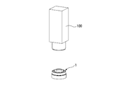
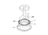
従来、玉軸受の製造や検査等において、玉の位相を検出することが要求されており、種々の方法により行なわれている。第1の方法としては、図5に示すように、カメラ100により、軸受1の画像を取り込み、画像処理を行なう事で軸受1のボールの位置を求め、位相を検出している。第2の方法では、変位センサや光電センサを用い、光量、又は変位情報のみに閾値を設け、この値によりボールの位置を求める。第3の方法では、図6に示すように、位置決めピン200,201を使用し、このピン200,201を揺動させながら軸受1の内輪2と外輪3の間に下降させ、ボールとボールとの間にピン200,201を挿入することでボールの位相を合わせている。なお、出願人は、提示すべきこれらの方法に関する先行技術文献を見出せなかった。
Conventionally, in the manufacture and inspection of ball bearings, it has been required to detect the phase of the ball, and various methods have been used. As a first method, as shown in FIG. 5, an image of the
しかしながら、第1の方法では、装置が複雑になり、価格が高くなるという問題がある。また、第2の方法では、対象物の光沢や油付着等の要因により誤検出が多く、装置稼働率低下の原因となっていた。第3の方法では、ピン200,201がボール頂点に下降した場合には、位相を合わせることができず、また、軸受1と接触して強制的に位相を合わせるので、ゴミが発生する等の問題がある。
However, the first method has a problem that the apparatus becomes complicated and the price becomes high. Further, in the second method, there are many false detections due to factors such as the gloss of the object and the oil adhesion, which causes a reduction in the apparatus operating rate. In the third method, when the
本発明は、上述した課題に鑑みて為されたものであり、その目的は、安価なセンサと信号処理によって、正確にボールの位相を検出することができる玉軸受のボール位相検出方法を提供することにある。 The present invention has been made in view of the above-described problems, and an object of the present invention is to provide a ball phase detection method for a ball bearing that can accurately detect the phase of a ball by using an inexpensive sensor and signal processing. There is.
(1) センサが軸受の軸方向側方で対向するように前記センサ及び前記軸受を設置する工程と、
前記軸受を回転させながら、前記軸受内に挿入されたボール又は保持器と前記センサとの距離に応じた信号を検出する工程と、
前記検出された信号と前記軸受の回転角度情報とを制御装置に取り込む工程と、
前記制御装置にて、前記検出された信号のうち、予め設定した閾値を越えた部分に関して最小二乗法を用いて2次関数を求める工程と、
求められた前記2次関数から得られる前記閾値に対応する2つの回転角度情報の差分が予め決められた範囲にある場合に前記2次関数を前記ボールの位置として、前記ボールの頂点位置を判断する工程と、
を備えることを特徴とする玉軸受のボール位相検出方法。
なお、「ボールの頂点位置」とは、センサとの距離が最も近いボール上の位置を意味し、保持器とセンサとの距離を検出する場合には、ボールの頂点位置は、検出された保持器とセンサとの距離が最も近い保持器の頂点位置に基づいて判断される。
(1) installing the sensor and the bearing such that the sensor faces the bearing in the axial direction;
Detecting a signal corresponding to the distance between the ball or the cage inserted into the bearing and the sensor while rotating the bearing;
Capturing the detected signal and rotation angle information of the bearing into a control device;
By the control device, of the detected signal; asking you to quadratic function using the least squares method with respect to the portion that exceeds a preset threshold value,
When the difference between two rotation angle information corresponding to the threshold value obtained from the obtained quadratic function is within a predetermined range, the apex position of the ball is determined using the quadratic function as the ball position. And a process of
A ball phase detection method for a ball bearing, comprising:
The “ball apex position” means the position on the ball that is closest to the sensor. When detecting the distance between the cage and the sensor, the ball apex position is the detected holding position. The distance between the cage and the sensor is determined based on the apex position of the cage.
本発明の玉軸受のボール位相検出方法によれば、センサを用いて、軸受を回転させながら、軸受内に挿入されたボール又は保持器とセンサとの距離に応じた信号を検出し、制御装置にて、検出された信号から最小二乗法を用いて2次関数を求め、ボールの頂点位置を判断するようにしたので、ノイズに影響されずに安定してボールの頂点位置を求めることができ、玉の位相を正確に且つ安価に検出することができる。 According to the ball phase detection method for a ball bearing of the present invention, a sensor is used to detect a signal corresponding to the distance between the ball or the cage inserted into the bearing and the sensor while rotating the bearing, and a control device. Since the quadratic function is obtained from the detected signal using the least square method and the vertex position of the ball is judged, the vertex position of the ball can be obtained stably without being affected by noise. The phase of the ball can be detected accurately and inexpensively.
以下、本発明に係る玉軸受の位相検出方法について、図面を参照して詳細に説明する。 Hereinafter, a phase detection method for a ball bearing according to the present invention will be described in detail with reference to the drawings.
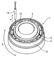
図1及び図2に示すように、本発明の位相検出装置10は、モータ11によって治工具12上に配置される玉軸受1を回転駆動すると共に、玉軸受1の軸方向側面に対向配置されてボール4の位相情報を検出するセンサ13を備える。また、これらモータ11及びセンサ13は、制御装置14と電気的に接続されている。
As shown in FIGS. 1 and 2, the
センサ13は、変位センサ或いは光電センサであり、図2に示すように、玉軸受1の内輪2、外輪3の間、具体的には、ボール4の中心軌道位置上の所定の位置に設置される。
The
そして、位相検出装置10は、玉軸受1を回転させながら、玉軸受1内に挿入された保持器5とセンサ13との距離に応じた信号を検出する。ここで、本実施形態では、玉軸受1の保持器5が鉄製であるため、ボール4の中心軌道位置が保持器5で覆われていることから、センサ13は、保持器5との距離を検出する。なお、センサ13は、保持器5との距離を検出する代わりに、可能であれば、軸受1内に挿入されたボール4との距離を検出しても良い。
Then, the
ここで、モータ11は、サーボモータ等の回転角度を読み取れる駆動源からなり、センサ13から出力されるアナログ出力信号は、回転角度に同期して機械の制御装置14に取り込まれる。
Here, the motor 11 includes a drive source that can read the rotation angle, such as a servo motor, and an analog output signal output from the
そして、制御装置14内に取り込まれたデータにより、最小二乗法を用いて、検出されたアナログ出力信号から近似2次関数を求める。この2次関数の係数から、ボール4の頂点位置を判断し、ボール4の位相を検出している。
Then, an approximate quadratic function is obtained from the detected analog output signal using the least square method based on the data captured in the control device 14. From the coefficient of the quadratic function, the vertex position of the
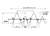
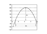
図3は、2ピッチ分をサンプリングした、センサ13から得られた信号を示している。信号には、検出したいボール4の位相情報の他に、リベット部やノイズ等の情報が含まれる。この情報から正確にボール4の位置を検出する為、センサ出力の最下点(センサからの距離が最も離れた位置)から予め設けた閾値(設定値1)を越えた部分に関して、それぞれ最小二乗法を用いて、上に凸な2次関数(y=ax2+bx+c)を求める。この2次関数において、xは回転角度、又は玉軸受1のボール中心軌道の周方向位置を表し、yはセンサ13と保持器5との距離を測定して得られるセンサ出力を表す。求めた2次関数が、ボール部分かどうかの判断は、図4に示した予め設けた閾値(y=0とする)における各Δxの値が、予め決められた範囲にあるかどうかで決定される。ここで、Δxは、

より求めることができる。図3に示したように、ボール部(Δx1)とそうでない部分(Δx2)では、幅が大きく異なることから、安定してボール部分と判断する事が可能である。
FIG. 3 shows a signal obtained from the
It can be obtained more. As shown in FIG. 3, since the widths of the ball part (Δx1) and the part (Δx2) which is not so differ greatly, it is possible to determine the ball part stably.
ボール部分と判断された2次関数(y=ax2+bx+c)について、ボール部分の頂点の座標(x,y)は、
従って、本実施形態のボール位相検出方法によれば、センサ13を用いて、軸受1を回転させながら、軸受1内に挿入されたボール4又は保持器5とセンサ13との距離に応じた信号を検出し、制御装置14にて、検出された信号から最小二乗法を用いて2次関数を求め、ボール4の頂点位置を判断するようにしたので、ノイズに影響されずに安定してボール4の頂点位置を求めることができ、ボール4の位相を正確に且つ安価に検出することができる。
Therefore, according to the ball phase detection method of the present embodiment, a signal corresponding to the distance between the
なお、本発明は、前述した実施形態に限定されるものではなく、適宜な変形、改良等が可能である。
本発明の位相検出装置は、例えば、ボール4にグリースを塗布するグリース封入装置や、軸受1のラジアル隙間を測定する軸受検査装置に適用可能である。
In addition, this invention is not limited to embodiment mentioned above, A suitable deformation | transformation, improvement, etc. are possible.
The phase detection device of the present invention can be applied to, for example, a grease filling device that applies grease to the
1 玉軸受
2 内輪
3 外輪
4 ボール
5 保持器
10 位相検出装置
13 センサ
14 制御装置
DESCRIPTION OF
Claims (1)
前記軸受を回転させながら、前記軸受内に挿入されたボール又は保持器と前記センサとの距離に応じた信号を検出する工程と、
前記検出された信号と前記軸受の回転角度情報とを制御装置に取り込む工程と、
前記制御装置にて、前記検出された信号のうち、予め設定した閾値を越えた部分に関して最小二乗法を用いて2次関数を求める工程と、
求められた前記2次関数から得られる前記閾値に対応する2つの回転角度情報の差分が予め決められた範囲にある場合に前記2次関数を前記ボールの位置として、前記ボールの頂点位置を判断する工程と、
を備えることを特徴とする玉軸受のボール位相検出方法。 Installing the sensor and the bearing so that the sensor faces the axial side of the bearing;
Detecting a signal corresponding to the distance between the ball or the cage inserted into the bearing and the sensor while rotating the bearing;
Capturing the detected signal and rotation angle information of the bearing into a control device;
By the control device, of the detected signal; asking you to quadratic function using the least squares method with respect to the portion that exceeds a preset threshold value,
When the difference between two rotation angle information corresponding to the threshold value obtained from the obtained quadratic function is within a predetermined range, the apex position of the ball is determined using the quadratic function as the ball position. And a process of
A ball phase detection method for a ball bearing, comprising:
Priority Applications (1)
| Application Number | Priority Date | Filing Date | Title |
|---|---|---|---|
| JP2007106189A JP4967775B2 (en) | 2007-04-13 | 2007-04-13 | Ball phase detection method for ball bearings |
Applications Claiming Priority (1)
| Application Number | Priority Date | Filing Date | Title |
|---|---|---|---|
| JP2007106189A JP4967775B2 (en) | 2007-04-13 | 2007-04-13 | Ball phase detection method for ball bearings |
Publications (3)
| Publication Number | Publication Date |
|---|---|
| JP2008261797A JP2008261797A (en) | 2008-10-30 |
| JP2008261797A5 JP2008261797A5 (en) | 2010-04-08 |
| JP4967775B2 true JP4967775B2 (en) | 2012-07-04 |
Family
ID=39984372
Family Applications (1)
| Application Number | Title | Priority Date | Filing Date |
|---|---|---|---|
| JP2007106189A Active JP4967775B2 (en) | 2007-04-13 | 2007-04-13 | Ball phase detection method for ball bearings |
Country Status (1)
| Country | Link |
|---|---|
| JP (1) | JP4967775B2 (en) |
Cited By (1)
| Publication number | Priority date | Publication date | Assignee | Title |
|---|---|---|---|---|
| CN108061644A (en) * | 2017-10-23 | 2018-05-22 | 浙江蓝翔轴承有限公司 | Retainer steel ball takes off pearl detection device and detection method |
Families Citing this family (5)
| Publication number | Priority date | Publication date | Assignee | Title |
|---|---|---|---|---|
| CN104122086B (en) * | 2014-08-11 | 2016-05-04 | 长沙理工大学 | Fault Diagnosis of Gearbox for Wind Turbine method based on Kriging model |
| JP6303942B2 (en) * | 2014-09-12 | 2018-04-04 | 日本精工株式会社 | Ball bearing grease enclosing method and enclosing device, and ball bearing manufacturing method |
| CN105003813B (en) * | 2015-06-20 | 2017-12-19 | 新昌县三和轴承有限公司 | There is one kind commutative bearing to apply lube plant |
| JP6834174B2 (en) * | 2016-05-13 | 2021-02-24 | 株式会社ジェイテクト | Visual inspection method and visual inspection equipment |
| CN109488697A (en) * | 2018-11-28 | 2019-03-19 | 苏州铁近机电科技股份有限公司 | A kind of bearing assembles flowing water processing line automatically |
Family Cites Families (8)
| Publication number | Priority date | Publication date | Assignee | Title |
|---|---|---|---|---|
| JPS61138139A (en) * | 1984-12-10 | 1986-06-25 | Honda Motor Co Ltd | Method and device for measuring dynamic behavior of ball bearings |
| JP3206201B2 (en) * | 1993-04-08 | 2001-09-10 | 株式会社日立製作所 | Projection exposure method |
| JPH0894890A (en) * | 1994-09-28 | 1996-04-12 | Nec Corp | Optical axis alignment method for optical fiber |
| JP3181201B2 (en) * | 1995-07-10 | 2001-07-03 | 名古屋電機工業株式会社 | Moving object detection method |
| WO2001018521A1 (en) * | 1999-09-06 | 2001-03-15 | Anritsu Corporation | System for measuring wavelength dispersion of optical fiber |
| JP2004239746A (en) * | 2003-02-06 | 2004-08-26 | Nsk Ltd | Apparatus and method for measuring revolution speed of bearing rolling element and bearing diagnosis apparatus |
| JP4218361B2 (en) * | 2003-02-07 | 2009-02-04 | 株式会社ジェイテクト | Rolling bearing unit with sensor |
| JP2006234080A (en) * | 2005-02-25 | 2006-09-07 | Toyota Motor Corp | Rolling bearing device |
-
2007
- 2007-04-13 JP JP2007106189A patent/JP4967775B2/en active Active
Cited By (1)
| Publication number | Priority date | Publication date | Assignee | Title |
|---|---|---|---|---|
| CN108061644A (en) * | 2017-10-23 | 2018-05-22 | 浙江蓝翔轴承有限公司 | Retainer steel ball takes off pearl detection device and detection method |
Also Published As
| Publication number | Publication date |
|---|---|
| JP2008261797A (en) | 2008-10-30 |
Similar Documents
| Publication | Publication Date | Title |
|---|---|---|
| JP4967775B2 (en) | Ball phase detection method for ball bearings | |
| JP5025442B2 (en) | Tire shape inspection method and apparatus | |
| JP5655936B2 (en) | Workpiece defect detection device | |
| US9322642B2 (en) | Apparatus and method for determining a distance measure on wound-up materials | |
| EP1491936A3 (en) | Focus detecting method of an image pickup device and focus detection mechanism | |
| EP2851650A1 (en) | Tire shape inspection method and tire shape inspection device | |
| JP2005292136A (en) | Multi-resolution inspection system and operation method thereof | |
| CN112797919A (en) | A method for detecting three-dimensional dimensions of elevator traction sheave grooves | |
| JP5794895B2 (en) | Cylindrical appearance inspection device | |
| JP5835616B2 (en) | Ball behavior measuring method and ball behavior measuring device | |
| JP2019106402A (en) | Substrate inspection apparatus, surface inspection method, and computer program | |
| JP6035116B2 (en) | Circular product inspection apparatus and method | |
| JP2012163338A (en) | Eddy current flaw detector and eddy current flaw detection method | |
| JP4931476B2 (en) | Image processing method and image processing apparatus characterized by method for measuring roundness | |
| JP4859127B2 (en) | Cylindrical automatic inspection method | |
| JP5446502B2 (en) | Chassis dynamometer | |
| CN119146869A (en) | Differential mechanism assembly detection method, device and system based on visual detection | |
| CN119022815A (en) | Sealing ring inspection method and sealing ring inspection device | |
| JP5605491B2 (en) | Chassis dynamometer | |
| JP2740630B2 (en) | Non-contact measurement device | |
| JPH07117495B2 (en) | Steel pipe weld detection method | |
| JP2004108406A (en) | Method and apparatus for measuring rotational accuracy of rolling bearing | |
| JP5322390B2 (en) | Round bar inspection device and round bar inspection method | |
| KR102645396B1 (en) | Apparatus for detecting tool shape abnormality and method for detecting tool shape abnormality | |
| JP6595800B2 (en) | Defect inspection apparatus and defect inspection method |
Legal Events
| Date | Code | Title | Description |
|---|---|---|---|
| A521 | Written amendment |
Free format text: JAPANESE INTERMEDIATE CODE: A523 Effective date: 20100218 |
|
| A621 | Written request for application examination |
Free format text: JAPANESE INTERMEDIATE CODE: A621 Effective date: 20100218 |
|
| A977 | Report on retrieval |
Free format text: JAPANESE INTERMEDIATE CODE: A971007 Effective date: 20111213 |
|
| A131 | Notification of reasons for refusal |
Free format text: JAPANESE INTERMEDIATE CODE: A131 Effective date: 20111220 |
|
| A521 | Written amendment |
Free format text: JAPANESE INTERMEDIATE CODE: A523 Effective date: 20120215 |
|
| TRDD | Decision of grant or rejection written | ||
| A01 | Written decision to grant a patent or to grant a registration (utility model) |
Free format text: JAPANESE INTERMEDIATE CODE: A01 Effective date: 20120306 |
|
| A01 | Written decision to grant a patent or to grant a registration (utility model) |
Free format text: JAPANESE INTERMEDIATE CODE: A01 |
|
| A61 | First payment of annual fees (during grant procedure) |
Free format text: JAPANESE INTERMEDIATE CODE: A61 Effective date: 20120319 |
|
| FPAY | Renewal fee payment (event date is renewal date of database) |
Free format text: PAYMENT UNTIL: 20150413 Year of fee payment: 3 |
|
| R150 | Certificate of patent or registration of utility model |
Ref document number: 4967775 Country of ref document: JP Free format text: JAPANESE INTERMEDIATE CODE: R150 Free format text: JAPANESE INTERMEDIATE CODE: R150 |