JP4966039B2 - Network-compatible device and function providing method - Google Patents
Network-compatible device and function providing method Download PDFInfo
- Publication number
- JP4966039B2 JP4966039B2 JP2007023255A JP2007023255A JP4966039B2 JP 4966039 B2 JP4966039 B2 JP 4966039B2 JP 2007023255 A JP2007023255 A JP 2007023255A JP 2007023255 A JP2007023255 A JP 2007023255A JP 4966039 B2 JP4966039 B2 JP 4966039B2
- Authority
- JP
- Japan
- Prior art keywords
- component
- unit
- processing
- information
- function
- Prior art date
- Legal status (The legal status is an assumption and is not a legal conclusion. Google has not performed a legal analysis and makes no representation as to the accuracy of the status listed.)
- Expired - Fee Related
Links
- 238000000034 method Methods 0.000 title claims description 45
- 230000002194 synthesizing effect Effects 0.000 claims description 5
- 230000015572 biosynthetic process Effects 0.000 claims description 2
- 238000003786 synthesis reaction Methods 0.000 claims description 2
- 238000012545 processing Methods 0.000 description 145
- 230000006870 function Effects 0.000 description 107
- 230000008569 process Effects 0.000 description 28
- 238000007906 compression Methods 0.000 description 26
- 230000006835 compression Effects 0.000 description 24
- 238000005516 engineering process Methods 0.000 description 15
- 238000003384 imaging method Methods 0.000 description 15
- 238000010586 diagram Methods 0.000 description 13
- 238000004458 analytical method Methods 0.000 description 4
- 238000004364 calculation method Methods 0.000 description 4
- 238000004891 communication Methods 0.000 description 3
- 238000011161 development Methods 0.000 description 3
- 230000010354 integration Effects 0.000 description 3
- 230000007246 mechanism Effects 0.000 description 3
- 230000008859 change Effects 0.000 description 2
- 238000006243 chemical reaction Methods 0.000 description 2
- 238000007796 conventional method Methods 0.000 description 2
- 238000013461 design Methods 0.000 description 2
- 238000012917 library technology Methods 0.000 description 2
- 230000003044 adaptive effect Effects 0.000 description 1
- 238000013459 approach Methods 0.000 description 1
- 238000004519 manufacturing process Methods 0.000 description 1
- 238000012986 modification Methods 0.000 description 1
- 230000004048 modification Effects 0.000 description 1
- 230000006855 networking Effects 0.000 description 1
- 230000003287 optical effect Effects 0.000 description 1
- 230000004044 response Effects 0.000 description 1
- 230000003068 static effect Effects 0.000 description 1
Images


Classifications
-
- H—ELECTRICITY
- H04—ELECTRIC COMMUNICATION TECHNIQUE
- H04L—TRANSMISSION OF DIGITAL INFORMATION, e.g. TELEGRAPHIC COMMUNICATION
- H04L67/00—Network arrangements or protocols for supporting network services or applications
- H04L67/01—Protocols
- H04L67/12—Protocols specially adapted for proprietary or special-purpose networking environments, e.g. medical networks, sensor networks, networks in vehicles or remote metering networks
- H04L67/125—Protocols specially adapted for proprietary or special-purpose networking environments, e.g. medical networks, sensor networks, networks in vehicles or remote metering networks involving control of end-device applications over a network
-
- H—ELECTRICITY
- H04—ELECTRIC COMMUNICATION TECHNIQUE
- H04L—TRANSMISSION OF DIGITAL INFORMATION, e.g. TELEGRAPHIC COMMUNICATION
- H04L9/00—Cryptographic mechanisms or cryptographic arrangements for secret or secure communications; Network security protocols
- H04L9/40—Network security protocols
Description
本発明は、ネットワーク対応機器及び機能提供方法に関する。 The present invention relates to a network-compatible device and a function providing method.
電子計算機技術の進歩により、従来は単一の機能しか有せず相互に接続することができなかった事務機器や家庭用機器においても、ネットワークを通じた処理の連携を実現するための機能が搭載されるようになった。 Due to advances in computer technology, office equipment and home appliances, which previously had only a single function and could not be connected to each other, are now equipped with functions that enable processing to be linked through a network. It became so.
このようなネットワークを通じた処理の連携を実現するための技術として、UPnP(Universal Plug and Play)がある。UPnPは、機器のインタフェース情報の交換と機能の呼び出しとを実現するための技術である。同様の目的や機能を有する別の技術としては、JiniやJxta等が存在する。 There is UPnP (Universal Plug and Play) as a technique for realizing the cooperation of processing through such a network. UPnP is a technology for realizing exchange of device interface information and calling of functions. As other technologies having similar purposes and functions, there are Jini, Jxta, and the like.
UPnPでは幾つかの機器のタイプに関してはインタフェース情報の標準化がされている。そのため、事前にどのようなタイプの機器の機能を用いるのかが確定できる場合には、前記インタフェース情報に対応した処理を予め実装する形態をとることが可能となる。しかし、機器固有の機能を最大限に生かすため、標準化された仕様を独自に拡張するような場合や、或いは標準仕様そのものが機器開発後に拡張された場合等では、拡張された部分に関するインタフェース情報の取り扱いに関して予め決定しておくことはできない。 In UPnP, interface information is standardized for several types of devices. Therefore, when it is possible to determine in advance what type of device function to use, it is possible to take a form in which processing corresponding to the interface information is implemented in advance. However, in order to make the best use of the device-specific functions, when the standardized specifications are expanded independently, or when the standard specifications themselves are expanded after device development, interface information on the expanded part The handling cannot be determined in advance.
以上説明してきたUPnPは主に家庭用機器で構成されるホームネットワークをターゲットにしたものであるが、次に事務機器で構成される業務用ネットワークにおける同様の技術として、Web Serviceがある。 The UPnP described above is targeted at a home network mainly composed of home devices. Next, as a similar technology in a business network composed of office devices, there is Web Service.
Web Serviceは、企業間の商取引を担う大規模なものから単体の事務用機器にいたるまで様々な規模・種類に対応が可能な柔軟な技術である。そのため、複数のWeb Service同士を繋ぎ合わせて業務ソリューションやアプリケーションを構築するスタイルが、次世代のソフトウェア開発の主流になると予測されている。 Web Service is a flexible technology that can handle various scales and types ranging from large-scale business that handles business transactions between companies to single office equipment. For this reason, it is predicted that the style of building business solutions and applications by connecting a plurality of Web Services will become the mainstream of next-generation software development.
Web Serviceでは、インタフェース情報はWSDL(Web Service Description Language)によって定義される。WSDLを用いたインタフェース情報は、開発者が独自に定義したデータ構造を用いることができる等、UPnPに比較してより複雑な内容を含んだものとなる場合が多い。更にWeb Serviceでは、一つのSOAP(Simple Object Access Protocol)メッセージに複数のメッセージスキーマ情報に基づいた情報を混在させることができる。ここで、メッセージスキーマ情報とは、メッセージの構造と記述方法とを示した情報である。 In Web Service, interface information is defined by WSDL (Web Service Description Language). Interface information using WSDL often includes more complicated content than UPnP, such as the ability to use a data structure uniquely defined by the developer. Further, in Web Service, information based on a plurality of message schema information can be mixed in a single SOAP (Simple Object Access Protocol) message. Here, the message schema information is information indicating a message structure and a description method.
このようにWeb Serviceではサービスのインタフェース情報であるメッセージスキーマ情報の自由度が高い。そのため、これを処理する機器にはUPnPよりも更に高度なXML(Extensible Markup Language)処理とメッセージング処理とが求められることとなる。 In this way, Web Service has a high degree of freedom in message schema information that is service interface information. Therefore, a device that processes this is required to have XML (Extensible Markup Language) processing and messaging processing that are more advanced than UPnP.
しかもWeb Serviceにおいては、インタフェース情報の内容そのものに関する標準化はなされておらず、UPnPのように機器のタイプに応じて標準的なインタフェース情報が定義されていることを期待することはできない。 Moreover, in the Web Service, standardization regarding the contents of the interface information itself has not been made, and it cannot be expected that standard interface information is defined according to the type of device as in UPnP.
更に、対象とする業務ソリューションの成長や拡大に伴って、必要とされるインタフェース情報も随時変更をしていく可能性が高い。 Furthermore, it is highly likely that necessary interface information will be changed as needed as the target business solution grows and expands.
Web Serviceに対応した機器においては、インタフェース情報が任意に変更されていくような状況でも、必要となるソフトウェアを適応的に実行できることが求められている。これは特に業務ソリューションに対応することを目的とした機器の場合に顕著である。 In a device compatible with Web Service, it is required that necessary software can be adaptively executed even in a situation where interface information is arbitrarily changed. This is particularly noticeable for devices intended to support business solutions.
機器の機能を用いるためのメッセージスキーマ情報とそれを解釈して処理するための機器内部のソフトウェアとの関係が固定的(静的)になっていると、以下のような問題がある。つまり、Web Serviceのように1つのSOAPメッセージに複数のメッセージスキーマ情報に基づく情報が混在する環境では、受信したメッセージの内容を全て処理できない可能性がでてくる。 If the relationship between the message schema information for using the function of the device and the software inside the device for interpreting and processing it is fixed (static), there are the following problems. That is, in an environment where information based on a plurality of message schema information is mixed in one SOAP message as in Web Service, there is a possibility that the contents of the received message cannot be processed entirely.
パーソナルコンピュータや大型の計算機では計算機資源の制約が比較的低いため、処理する可能性のある全てのメッセージスキーマ情報に対応したメッセージ処理プログラムを待機させておくといったことも可能である。しかしながら、計算機資源の制約を意識しなければならない組み込み機器ではこのようなことは困難である。そのため、処理実行中において処理対象となったメッセージのメッセージスキーマ情報を基に、対応するメッセージ処理プログラムを動的に選択して実行する仕組みが必要となる。 Since personal computers and large computers have relatively low computer resource constraints, it is possible to wait for message processing programs corresponding to all message schema information that may be processed. However, this is difficult for embedded devices that must be aware of computer resource constraints. Therefore, a mechanism for dynamically selecting and executing the corresponding message processing program based on the message schema information of the message to be processed during the processing is required.
更に、新しく選択されたメッセージ処理プログラムを有効に使用するには、自分自身が処理可能なメッセージスキーマ情報が変化したことを、機器の機能を用いる相手に通知する必要がある。 Further, in order to effectively use the newly selected message processing program, it is necessary to notify the other party using the function of the device that the message schema information that can be processed by itself has changed.
このような問題に対応して、機器に格納されるソフトウェアの取捨選択を自動的に実行する技術として、例えば以下のようなものがある。 As a technique for automatically executing selection of software stored in the device in response to such a problem, for example, the following is available.
通常のオペレーティングシステムソフトウェアや一部のアプリケーションソフトウェアが実現しているソフトウェアモジュールの管理を行うために使用している技術があり、ここではダイナミックロードライブラリ技術と呼ぶ。ダイナミックロードライブラリ技術は、機能の異なる複数のライブラリソフトウェアをアプリケーションソフトウェアの要求に応じて動的にロード或いはアンロードすることを可能とする技術である。ライブラリソフトウェアが提供する機能が必要とされない限りライブラリソフトウェアは読み込まれて実行されることはなく、また読み込まれた後も多くの計算機環境においてはメモリイメージを共有できる。 There is a technique used to manage software modules implemented by normal operating system software and some application software, and is called dynamic load library technique here. The dynamic load library technique is a technique that enables a plurality of library software having different functions to be dynamically loaded or unloaded according to the request of application software. Unless the functions provided by the library software are required, the library software is not read and executed, and a memory image can be shared in many computer environments even after being read.
しかしながら、本技術のみでは「どのようなライブラリが必要か」といった判断はアプリケーションソフトウェアが実施しなければならなかった。したがって、複数のメッセージスキーマ情報と複数のメッセージ処理プログラムとを相互に結びつける場合、全てを各々のアプリケーションが判断しなければならない構造となってしまう。 However, with this technology alone, it was necessary for the application software to determine “what kind of library is necessary”. Therefore, when a plurality of message schema information and a plurality of message processing programs are linked to each other, a structure is required in which each application must judge all of them.
更に、プログラムをコンポーネントソフトウェアとして格納し、管理・実行する技術があり、ここではコンポーネントコンテナ技術と呼称する。本技術はダイナミックロードライブラリ技術を進化させたものであり、システム全体は個別の機能を実現するコンポーネントソフトウェアと、それを複数格納して実行することのできるコンテナソフトウェアと、によって構成される。ユーザからのリクエストはコンテナソフトウェアが受信し、コンテナソフトウェアからの判断によって適切なコンポーネントソフトウェアが実行を開始する。これによればコンポーネントソフトウェアはユーザからのリクエストがなければ実行を開始しなくてもよく、またリクエストが無い場合は停止することも可能なため、適応的なソフトウェアの選択と実行とが可能となっている。 Furthermore, there is a technique for storing, managing, and executing a program as component software, which is referred to herein as a component container technique. This technology is an evolution of the dynamic load library technology, and the entire system is composed of component software that realizes individual functions and container software that can store and execute a plurality of them. The request from the user is received by the container software, and the appropriate component software starts executing according to the determination from the container software. According to this, it is not necessary to start the execution of the component software if there is no request from the user, and it is also possible to stop the execution if there is no request, so that it is possible to select and execute the adaptive software. ing.
しかしながら、ダイナミックロードライブラリ技術と同様に、本技術はあくまでもソフトウェアの動的な選択に使用可能な環境を提供するだけであり、これのみでメッセージスキーマ情報にあわせたメッセージ処理プログラムの自動処理が実現できるとは言えない。 However, as with the dynamic load library technology, this technology only provides an environment that can be used for dynamic software selection, and with this alone, automatic processing of a message processing program that matches message schema information can be realized. It can not be said.
これらの一般技術は、ソフトウェアの動的な取捨選択を実現するための基本的な処理技術として充分に有用であるが、こうした単独の技術だけでは課題であるメッセージスキーマ情報にあわせたメッセージ処理プログラムの自動処理が実現できるとは言えない。また自機器におけるインタフェース情報の更新も行うことはできない。 These general technologies are sufficiently useful as basic processing technologies for realizing dynamic software selection, but the message processing program that matches the message schema information, which is a problem only with these single technologies, is used. It cannot be said that automatic processing can be realized. Also, the interface information in the own device cannot be updated.
更に、特許文献に記載の従来技術としては以下のようなものがある。
まず特許文献1に記載の従来技術は、同一の用途として使用されるデータベースではなくても、スキーマを統合することができるスキーマ統合変換システムを提供する技術である。スキーマ統合変換システムでは、複数の異なったデータスキーマを、予め抽象スキーマグラフと呼んでいるデータから生成するようにすることで統合を図っている。
Furthermore, there are the following as conventional techniques described in the patent literature.
First, the conventional technology described in Patent Document 1 is a technology that provides a schema integration conversion system that can integrate schemas even if they are not databases used for the same application. In the schema integration conversion system, integration is achieved by generating a plurality of different data schemas from data called an abstract schema graph in advance.
次に、特許文献2に記載の従来技術は、プログラムの仕様作成時に、プログラムの特殊化要求に応じた仕様の作成と、プログラム作成作業とへの結果の自動的な反映を可能にする技術である。この技術では、プログラムひな型情報と外部データに対するデータ定義の割り当て情報とを基に、プログラム特殊化装置がプログラムひな型情報を特殊化してプログラム仕様として生成する。プログラム開発時においてデータ定義に対応したプログラムを迅速に開発することを目的としている。 Next, the prior art described in Patent Document 2 is a technology that enables specification creation according to a program specialization request and automatic reflection of the result to the program creation work when creating the program specification. is there. In this technique, the program specializing apparatus specializes the program template information and generates it as a program specification based on the program template information and the data definition allocation information for the external data. The purpose is to quickly develop a program that supports data definition during program development.
更に、特許文献3に記載の従来技術は、実行時にメッセージハンドラのエントリを動的に管理することにより、適切なメッセージハンドラを呼び出すための機構を実現することを目的としている。交換するメッセージ中のオペレーションやデータにワールドワイドでユニックな識別子を付与することにより、適切なメッセージハンドラを探し、存在すればそれを選択する。そして、存在しなければ適切なプログラムモジュールをロード/リンクした上でその中にあるメッセージハンドラを選択し、呼び出す技術である。 Furthermore, the prior art described in Patent Document 3 aims to realize a mechanism for calling an appropriate message handler by dynamically managing message handler entries during execution. Search for an appropriate message handler by assigning a globally unique identifier to the operation or data in the message to be exchanged, and select it if it exists. If the program module does not exist, an appropriate program module is loaded / linked and a message handler is selected and called.
上述した特許文献1の抽象スキーマを用いるアプローチは、Web Serviceを用いた機器のメッセージ交換においては上述したようにメッセージスキーマ情報の自由度が高く、取り扱うメッセージスキーマ情報が抽象スキーマへと還元できる保証が無い。 The approach using the abstract schema of Patent Document 1 described above has a high degree of freedom of message schema information as described above in the message exchange of the device using Web Service, and there is a guarantee that the message schema information to be handled can be reduced to the abstract schema. No.
また、上述した特許文献2の技術では、プログラム実行時においてデータ定義をキーにプログラムを切り替えることはできない。即ち、実行時におけるメッセージスキーマ情報にあわせたメッセージ処理プログラムの動的な自動処理は実現できない。 Also, with the technique of Patent Document 2 described above, it is not possible to switch programs using data definition as a key during program execution. That is, the dynamic automatic processing of the message processing program according to the message schema information at the time of execution cannot be realized.
また、上述した特許文献3の技術では、メッセージのインスタンスに、それを処理するプログラムを特定可能なIDを付与するため、メッセージの発行側と受信側との了解事項としてID付与を取り扱わなければならない。Web Serviceを用いた機器のメッセージ交換においては、取り扱うメッセージスキーマ情報において常にこうしたIDが付与されていると期待することはできない。また、送受信したメッセージに対してスキーマ処理を行うのではないため、自機器におけるインタフェース情報の更新を行うこともできない。 Further, in the technique of Patent Document 3 described above, since an ID that can identify a program that processes the message is assigned to the instance of the message, ID assignment must be handled as an understanding matter between the message issuer and the receiver. . In message exchange of a device using Web Service, it cannot be expected that such an ID is always given in message schema information to be handled. Further, since the schema processing is not performed on the transmitted / received message, the interface information in the own device cannot be updated.
このように、従来技術はいずれもソフトウェアに関する処理効率性や柔軟なメッセージスキーマの取り扱いといった課題に対しては一定の解決策を提供する。しかしながら、業務ソリューションに対応する場合におけるWeb Serviceのような、インタフェース情報が随時変更されていくような状況において、必要となるソフトウェアを適応的に実行するという課題に対して十分な解決策を提供していない。 As described above, all of the conventional techniques provide a certain solution to problems such as processing efficiency related to software and flexible message schema handling. However, it provides a sufficient solution to the problem of adaptively executing the necessary software in a situation where interface information is constantly changing, such as Web Service when dealing with business solutions. Not.
本発明は、機器やコンポーネントソフトウェアのインタフェース情報が変更されているような状況においても、機器が提供する機能に係るコンポーネントソフトウェアを適応的に実行できるようにすることを目的とする。 An object of the present invention is to make it possible to adaptively execute component software related to a function provided by a device even in a situation where interface information of the device or component software is changed.
そこで、本発明のネットワーク対応機器は、各々機能を提供し、コンポーネントソフトウェアが提供する機能をコンポーネントソフトウェアの外部から利用するための情報を記述したインタフェース情報を公開する複数のコンポーネントソフトウェアを管理し、前記コンポーネントソフトウェアの実行を制御する管理手段と、前記管理手段に対してコンポーネントソフトウェアの登録を行う登録手段と、前記管理手段において管理されているコンポーネントソフトウェアの前記インタフェース情報に基づいて、ネットワーク対応機器が提供する機能を外部機器から利用するための情報を記述したインタフェース情報を合成する合成手段と、を有し、前記管理手段で管理されているコンポーネントソフトウェアでは提供できない機能の利用要求が外部機器よりなされると、前記登録手段は、前記機能を提供することができるコンポーネントソフトウェアを前記ネットワーク対応機器の外部から前記管理手段に登録し、前記合成手段は、前記登録されたコンポーネントソフトウェアのインタフェース情報に基づいて、前記ネットワーク対応機器が提供する機能のインタフェース情報を更新する。 Therefore, the network-compatible device of the present invention manages a plurality of component software that provides functions, and discloses interface information describing information for using the functions provided by the component software from outside the component software. Provided by a network-compatible device based on management means for controlling execution of component software, registration means for registering component software with the management means, and the interface information of the component software managed by the management means synthesizing means for synthesizing the interface information functions describing information for use from an external device to, have a usage request function can not provide a component software that is managed by the management means When made from an external device, the registration unit registers component software capable of providing the function in the management unit from outside the network-compatible device, and the combining unit is an interface of the registered component software. Based on the information, the interface information of the function provided by the network compatible device is updated .
かかる構成とすることにより、例えば、機器の内部を構成しているコンポーネントソフトウェアのインタフェース情報を基に、機器としてのインタフェース情報を生成することができる。また、かかる構成とすることにより、例えば、自分自身の処理可能なサービスのインタフェース情報を更新していくことができる。よって、機器やコンポーネントソフトウェアのインタフェース情報が変更されているような状況においても、機器が提供する機能に係るコンポーネントソフトウェアを適応的に実行できるようにすることができる。 With such a configuration, for example, interface information as a device can be generated based on interface information of component software constituting the inside of the device. In addition, with this configuration, for example, the interface information of services that can be processed by itself can be updated. Therefore, it is possible to adaptively execute the component software related to the function provided by the device even in a situation where the interface information of the device or component software is changed.
また、本発明は、機能提供方法としてもよい。 Further, the present invention may be a function providing method.
本発明によれば、機器やコンポーネントソフトウェアのインタフェース情報が変更されているような状況においても、機器が提供する機能に係るコンポーネントソフトウェアを適応的に実行できるようにすることができる。 According to the present invention, it is possible to adaptively execute component software related to functions provided by a device even in a situation where interface information of the device or component software is changed.
以下、本発明の実施形態について図面に基づいて説明する。 Hereinafter, embodiments of the present invention will be described with reference to the drawings.
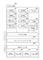
図1は、ネットワーク対応機器の処理(機能)の概要の一例を示した図である。なお、図1では本実施形態の処理概要を説明するために構成を簡略化している。本実施形態のソフトウェアを搭載したネットワーク対応機器の詳細な構造に関しては、後述する図2以降においてデジタルカメラ(デジタルカメラ機器)を例に説明を行う。 FIG. 1 is a diagram illustrating an example of an outline of processing (function) of a network-compatible device. In FIG. 1, the configuration is simplified in order to explain the processing outline of the present embodiment. The detailed structure of the network-compatible device in which the software of this embodiment is installed will be described by taking a digital camera (digital camera device) as an example in FIG.
ネットワーク対応機器301は、本実施形態のソフトウェア(又は機能)を搭載した機器であり、ネットワークを経由した通信機能を有する。機器を構成するソフトウェアとしては、まず基本的な処理を提供するオペレーティングシステム・ファームウェア部310が搭載されている。その上に構成される本実施形態のソフトウェア構成における特徴部分が、302から307までである。ネットワーク対応機器301の内部的な機能を構成する主要なソフトウェアは、コンポーネントソフトウェア(コンポーネント部)の単位で管理される。コンポーネントソフトウェアの詳細については、後述する図2を用いて説明する。
The network
コンポーネント管理部307は、コンポーネントソフトウェアを管理し、コンポーネントソフトウェアのメモリへのロードやアンロード、実行等の処理を行う。図1ではAコンポーネント部302及びBコンポーネント部303の2つのコンポーネントがコンポーネント管理部307によって管理されている状態を示しているが、管理対象となるコンポーネントソフトウェアの数は2つ以上でもよいし、1つでもよい。
The
また、コンポーネント管理部307は、コンポーネント制御情報306を用いて各コンポーネントソフトウェアの実行を制御する。コンポーネント制御情報306に関しては、後述する図3を用いて説明する。
In addition, the
コンポーネント更新部305は、コンポーネント管理部307において管理の対象となるコンポーネントを、外部のコンポーネントリポジトリ309より取得し、コンポーネント管理部307に登録する処理を実行する。コンポーネント更新部305は、コンポーネント管理部307が保持するコンポーネント群の情報を基にコンポーネントリポジトリ309に問い合わせを行い、コンポーネントリポジトリ309が返送するコンポーネントをコンポーネント管理部307に登録する。このことで、新しいコンポーネントを動的にネットワーク対応機器301に追加することや、既存のコンポーネントソフトウェアの内容をアップデート(更新)することが可能となる。コンポーネントリポジトリ309は、例えば、ネットワーク対応機器301と通信可能なサーバ上(サーバのメモリ上)に設けられる。
The
インタフェース合成部304は、搭載されているコンポーネントソフトウェアの機能を反映する形でネットワーク対応機器301全体のインタフェースを公開する。インタフェース合成部304は、コンポーネント管理部307が保持しているコンポーネントソフトウェアの各々のインタフェース情報を基に、ネットワーク対応機器全体としてのインタフェース情報を動的に生成して公開する。インタフェース合成部304によって公開されるネットワーク対応機器301全体としてのインタフェース情報は、例えば、Aコンポーネント部302が提供するインタフェースとBコンポーネント部303が提供するインタフェースとを反映させたものとなる。
The
但し、インタフェース合成部304は、コンポーネント管理部307が管理しているコンポーネントソフトウェアの中でも、特にネットワークにおいて外部に公開可能な機能を提供するコンポーネントソフトウェアのインタフェース情報を用いて合成を行う。従って、例えば、図1においてAコンポーネント部302が提供する機能はネットワークにおいて外部公開が可能な機能であるが、Bコンポーネント部303が提供する機能は全て内部的に用いられる機能であるとする。すると、インタフェース合成部304が合成して発行(又は公開)するインタフェース情報には、Bコンポーネント部303のインタフェース情報は反映されない。このようにして、インタフェース合成部304において生成されたネットワーク対応機器301全体のインタフェース情報は、外部機器(他の機器)308から利用可能となる。このインタフェース合成部304においてどのようにインタフェース情報が合成されるのかは、後述する図5において説明する。なお、外部機器308とは、例えば、コンピュータ等である。
However, the
次に、図2は、コンポーネントソフトウェアの一例を示す図である。ここで、コンポーネントソフトウェアとは、単独で幾つかの機能を提供することができるソフトウェアのまとまりである。図2では図1におけるAコンポーネント部302と、Bコンポーネント部303と、をより詳細に示している。
Next, FIG. 2 is a diagram illustrating an example of component software. Here, the component software is a group of software that can provide several functions independently. FIG. 2 shows the
Aコンポーネント部302は、機能F1と機能F2とを提供する。各機能はそれぞれインタフェース部によってコンポーネント外部から呼び出すことができる。Aコンポーネント部302においては、機能F1はインタフェース部(機能F1インタフェース部)404を通じて、コンポーネントソフトウェアの外部より呼び出せるように構成されている。また、機能F2はインタフェース部(機能F2インタフェース部)405を通じて、コンポーネントソフトウェアの外部より呼び出せるように構成されている。
また、Aコンポーネント部302の内部においては、機能F1を処理するための処理部(機能F1処理部)401と機能F2を処理するための処理部(機能F2処理部)402とが存在している。更に、Aコンポーネント部302の内部においては、この両処理部から共通して使用される内部的な機能を提供するための、共通内部処理部403も存在している。
The
In the
Bコンポーネント部303は、Aコンポーネント部302と異なり、ただ一つの機能である機能F3を提供する。従って、内部における処理部も機能F3処理部411のみが存在する。
このように、コンポーネントソフトウェアが機能インタフェース部(インタフェース部)において公開する機能は、Bコンポーネント部303のように1つであってもよいし、Aコンポーネント部302のように複数であってもよい。
Unlike the
As described above, the function that the component software discloses in the function interface unit (interface unit) may be one as in the
本実施形態のコンポーネントソフトウェアは、コンポーネントソフトウェアの外部に公開する機能を必ずインタフェース部によってのみ呼び出し可能となっている。言い換えると、本実施形態のコンポーネントソフトウェアは、提供する機能に関する要求をコンポーネントソフトウェア外部より受け付ける機構をインタフェース情報(又はインタフェース部)として公開している。
そのため、機能F1処理部401、機能F2処理部402、そして共通内部処理部403は、このAコンポーネント部302の機能を使用する外部からは隠蔽された存在となる。つまり、実際に機能F1インタフェース部404を使用する他のコンポーネントソフトウェア(つまり外部)からは、401、402、及び403の各処理部の存在は不可視である。逆に言えば、別のコンポーネントソフトウェアが401、402、403といった各処理部を直接呼び出して使用することはできない。これはもちろんBコンポーネント部303においても同様である。コンポーネントソフトウェアの機能は、必ず機能インタフェース部を通じて用いなければならない。これにより、本実施形態においてコンポーネントソフトウェア同士の依存性は単独では存在しない。
The component software of the present embodiment can always call a function disclosed outside the component software only by the interface unit. In other words, the component software according to the present embodiment discloses a mechanism for accepting a request regarding a function to be provided from outside the component software as interface information (or an interface unit).
Therefore, the function
また、本実施形態においてはコンポーネントソフトウェアの機能を利用するためのインタフェース部を呼び出すことができるのは、コンポーネント管理部307に限られている。各コンポーネントソフトウェアは、内部処理を相互に直接呼び出すことも許されていないし、公開されたインタフェースである機能インタフェース部を直接呼び出すことも許されていない。全てのコンポーネントソフトウェアは、コンポーネント管理部307からの制御によってのみ実行することができる。
In this embodiment, only the
コンポーネント管理部307は、コンポーネント制御情報306に記述された内容に基づいて、逐次各コンポーネントが提供している機能インタフェース部を実行していく。
The
次に、図3は、コンポーネント制御情報とコンポーネントソフトウェアとの関係の一例を示した図である。コンポーネント制御情報306は、実際のコンポーネントソフトウェアの実行を制御するための情報として、コンポーネント管理部307において管理されている情報である。コンポーネント制御情報306は、機器が直面する状況とその状況が生起したときに行う処理とを記述したものとなっており、機器が対応する状況の数だけ状況別にコンポーネント管理部307において保持される。
Next, FIG. 3 is a diagram illustrating an example of the relationship between component control information and component software. The
ここで状況とは、ネットワーク対応機器301に搭載されているソフトウェアに何かの働きかけがあった時に発生する、ソフトウェアで認識可能な一連の状態を示す。例えば、ネットワーク対応機器301の電源投入、電源断、ユーザからの操作(外部操作)、ネットワークからの処理要求、機器内部での状態変更等が本実施形態における状況の例として挙げられる。
Here, the status refers to a series of statuses that can be recognized by the software when something is applied to the software installed in the network
図3では、ネットワーク対応機器301が状況C1について直面した場合のコンポーネント制御情報306の記述を抜き出して例示している。状況C1が生起したことをネットワーク対応機器301が検出した場合には、図3に示される記述に基づいてコンポーネント管理部307が、コンポーネント管理部307の管理下にある各コンポーネントを実行する。状況C1における処理情報としては、機能F1インタフェース部404の実行及び機能F3インタフェース部414の実行が指示されている。従って、ネットワーク対応機器301に状況C1が生起した場合には、コンポーネント管理部307によって、Aコンポーネント部302における機能F1インタフェース部404がまず実行される。そして、次に、コンポーネント管理部307によって、Bコンポーネント部303における機能F3インタフェース部414が実行される。
In FIG. 3, the description of the
機能F1インタフェース部404の入力情報及び出力情報、機能F3インタフェース部414の入力情報及び出力情報といった各情報は、コンポーネント制御情報306における、状況C1が生起した場合に対応する処理の入出力情報に記載される。ここで、機能F1インタフェース部404の入力情報とは、機能F1インタフェース部404に入力値として指定される情報である。また、機能F1インタフェース部404の出力情報とは、機能F1インタフェース部404が処理結果として出力する情報である。また、機能F3インタフェース部414の入力情報とは、機能F3インタフェース部414に入力値として指定される情報である。また、機能F3インタフェース部414の出力情報とは、機能F3インタフェース部414が処理結果として出力する情報である。
Information such as input information and output information of the function
状況C1の場合に実行されるコンポーネントであるAコンポーネント部302とBコンポーネント部303との間でやりとりされる情報は、このコンポーネント制御情報306に基づいて、全てコンポーネント管理部307が管理する。
The
図4は、ネットワーク対応機器301がデジタルカメラ機器である場合の内部構成の一例を示した図である。デジタルカメラ機器600は、Web Service技術を用いることで、デジタルカメラ機器600の機能である撮影や画像取得等の処理を、ネットワークを介して制御可能としている。
FIG. 4 is a diagram illustrating an example of an internal configuration when the network
図4において、621から624までは、デジタルカメラ機器600が搭載するハードウェアの特徴的部分を示している。演算制御ハードウェア部620は、主に機器の制御に係る演算記憶制御を司る。演算制御ハードウェア部620が、ストレージ管理ハードウェア部622のハードディスク(又はROM)等に格納されているプログラムを実行することによって、上部ソフトウェア群を実現(機能)させる。なお、コンポーネント制御情報610等は、ストレージ管理ハードウェア部622のRAM、又はハードディスク、又はROM等に予め設定(又は定義)され、格納されている。
In FIG. 4,
画像処理ハードウェア部621は、デジタルカメラ機器600におけるレンズやCCDセンサー等の光学処理を含む撮像処理を実現するハードウェア一式を総称したもので、映像をデジタル化処理することを実現する。ストレージ管理ハードウェア部622は、画像処理ハードウェア部621等が撮影処理した画像を保持する。ストレージ管理ハードウェア部622は、不揮発性のRAMやハードディスク等を駆動するためのハードウェア一式を総称したものである。電源管理ハードウェア部623は、全てのハードウェア部に対して電源を供給するための装置を総称したもので、充電式バッテリーや外部入力電源の制御等を行う。ネットワーク処理ハードウェア部624は、デジタルカメラ機器600がネットワークを通じて外部と通信(有線又は無線を介した通信)するための手段を提供する。図4では説明の簡略化のため詳細を省略しているがこれ以外にも各ハードウェア部を相互に結びつけるバスハードウェア部や、演算制御ハードウェア部620の演算結果を記憶するための主記憶ハードウェア部等が存在する。
The image
更に図4の601から612までは、デジタルカメラ機器600が搭載するソフトウェア(又は情報)の特徴的部分を示している。基本的に図4は上述した図1のネットワーク対応機器301の構成をより具体的にしたものであるため、機器の種類に起因する相違に影響されない基本的な部分に関しては、図1における各部にそれぞれ対応したものとなっている。
Further,
オペレーティングシステム・ファームウェア部612は、図1におけるオペレーティングシステム・ファームウェア部310と同じものである。オペレーティングシステム・ファームウェア部612は、621から624までで示される各ハードウェア部を制御する手段を提供するための機能を有している。更にオペレーティングシステム・ファームウェア部612上で各コンポーネントソフトウェアの制御を実行するためのコンポーネント管理部611も、同様に図1におけるコンポーネント管理部307と同じものである。また、コンポーネント制御情報610も、図1におけるコンポーネント制御情報306と同じである。また、コンポーネント更新部609も、図1におけるコンポーネント更新部305と同じである。
The operating
これらの各処理部は、対象となる機器の種類や製造コスト、或いは要求性能等によって実装上の選択が変化する。例えばオペレーティングシステム・ファームウェア部612は、図4で示しているデジタルカメラ機器の場合にはRTOS(Real Time OS)系の実装が選択される場合が多い。しかしながら、対象となる機器の種類が複写機等の事務機器の場合、オペレーティングシステム・ファームウェア部612は、より高機能な一般OSの組み込み版が採用される場合がある。
Each of these processing units changes in mounting choice depending on the type of device to be processed, the manufacturing cost, or the required performance. For example, in the case of the digital camera device shown in FIG. 4, for the operating system /
更に601から608までは、デジタルカメラ機器600がWeb Serviceで制御可能なデジタルカメラ機器であるために必要となるソフトウェア処理部である。
Further,
撮影処理コンポーネント部601は、デジタルカメラ機器600としての基本的な機能である撮影処理を実行する。より具体的に説明すると、撮影処理コンポーネント部601は、画像処理ハードウェア部621を制御することで撮影処理を実現する。
The imaging
画像保持コンポーネント部602は、撮影処理コンポーネント部601が撮影した画像を保持する。より具体的に説明すると、画像保持コンポーネント部602は、ストレージ管理ハードウェア部622を制御することで画像の保存を実現する。
The image
これらの処理部は各ハードウェア部が提供する機能をソフトウェアから制御するために設けられているものである。しかしながらデジタルカメラ機器600は、更に、ネットワークを経由して制御が可能となる機能を有するために、ネットワーク処理を行うためのソフトウェア処理部も必要となる。
These processing units are provided to control functions provided by the respective hardware units from software. However, since the
撮影サービスコンポーネント部603は、撮影処理コンポーネント部601の機能及び画像保持コンポーネント部602の機能をサービスとしてネットワーク上に公開するための機能を提供する。
The imaging
HTTP処理コンポーネント部604は、HTTPプロトコルによる情報の送受信機能を提供する。WSDL処理コンポーネント部605は、デジタルカメラ機器600の機能をWeb Serviceで公開するためのインタフェース情報を記述するためのWSDLを処理する。
The HTTP
SOAP処理コンポーネント部606は、SOAPの仕様に基づいて送受信されたXMLメッセージを解釈する処理部である。XML処理コンポーネント部607は、XMLで記述された情報を解析し、各ソフトウェア処理部が処理可能な形態に変換したり、或いは各ソフトウェア処理部が処理した情報をXML形式に変換したりする処理を実行する。
The SOAP
SOAP処理コンポーネント部606は、SOAPの仕様に基づいて送受信されたXMLメッセージを解釈する処理部である。XML処理コンポーネント部607は、XMLで記述された情報を解析し、各ソフトウェア処理部が処理可能な形態に変換したり、或いは各ソフトウェア処理部が処理した情報をXML形式に変換したりする処理を実行する。
The SOAP
デジタルカメラ機器600が、あるSOAPメッセージを受信した場合には、HTTP処理コンポーネント部604が前記SOAPメッセージまずHTTPとして受け取り、これをXML処理コンポーネント部607が解析する。そして、XML処理コンポーネント部607が解析した結果をSOAP処理コンポーネント部606が処理する流れになる。より具体的な処理は、後述する図5において説明する。
When the
これら601から607までの各ソフトウェア処理部は、図1におけるAコンポーネント部302或いはBコンポーネント部303に相当するものである。即ち、図1におけるコンポーネント管理部307(図4におけるコンポーネント管理部611)においてメモリへのロードやアンロード、実行等が行われる対象となる処理部である。またこれらの処理部は、図3において示したようにコンポーネント制御情報306(図4におけるコンポーネント制御情報610)に具体的な処理の手順が定義されている。
Each of the
WSDL生成部608は、図1におけるインタフェース合成部304に対応するものである。デジタルカメラ機器600は、Web Serviceを用いた機器であるため、インタフェース情報はWSDLの仕様に準じて公開される。
The
次に、図5は、デジタルカメラ機器600が、ネットワークよりWeb Serviceに準拠したメッセージを受信して撮影の実行を行う際に発生する内部処理に関して、ソフトウェア各部が果たす処理を示した図である。図5Aは、処理のフローチャートを示した図である。図5Bは、各処理がデジタルカメラ機器600の内部のどの処理部において実施されたのかを示した図である。
Next, FIG. 5 is a diagram illustrating processing performed by each unit of software regarding internal processing that occurs when the
ステップS701において、コンポーネント管理部611は、デジタルカメラ機器600に搭載されている各コンポーネントソフトウェアのインタフェース情報を処理するインタフェース処理を実行する。より具体的に説明すると、コンポーネント管理部611は、デジタルカメラ機器600に搭載されている各コンポーネント部が提供するインタフェース情報を全て収集し、その中で機器の外部へ公開可能なもののみを選択する。各コンポーネント部とは、601、602、603、604、605、606、607の各コンポーネント部である。
In step S <b> 701, the
本実施形態においては、公開可能なサービスを提供するコンポーネントソフトウェアは撮影サービスコンポーネント部603のみである。そのため、コンポーネント管理部611は、撮影サービスコンポーネント部603が保持するインタフェース情報である画像取得インタフェース部754及び撮影実行インタフェース部753のみを収集する。ステップS701の処理は、デジタルカメラ機器600が機能を外部に公開する処理が実行開始する前に行われる。なお、この処理は、典型的にはデジタルカメラ機器600への電源が投入されたときや、デジタルカメラ機器600に対するネットワーク接続状況が変化したとき等に行われる。
In the present embodiment, the component software that provides a publicly available service is only the photographing
ステップS702において、WSDL生成部608は、ステップS701によって収集されたインタフェース情報を基に、デジタルカメラ機器600全体のインタフェースとなるWSDLを生成する処理を行う。より具体的には、WSDL生成部608は、画像取得インタフェース部754及び撮影実行インタフェース部753が提供する情報を基に、前記情報をWSDLの仕様に即した情報(WSDL情報)に変換する。このWSDL情報は、図5BにおけるWSDL(WSDL情報)710に示すように、画像取得インタフェース部754及び撮影実行インタフェース部753を呼び出すために必要な情報を記載したメッセージスキーマ情報を含んだ情報となる。
In step S <b> 702, the
ステップS703において、コンポーネント管理部611が、HTTP処理コンポーネント部604にステップS702において作成されたWSDL情報を登録することで、WSDL情報を公開する。これにより、ネットワークを通じてデジタルカメラ機器600の機能をどのように使用することができるのかが記述されたWSDL情報が、デジタルカメラ機器600の外部より取得できる状態となる。
In step S703, the
ステップS704において、外部機器308は、ステップS703において公開されたWSDL情報をデジタルカメラ機器600より取得する。外部機器308は、例えば、上述したようにコンピュータである。なお、WSDL情報の取得にはHTTPが用いられる。WSDL情報を取得した外部機器308は、以降はデジタルカメラ機器600の機能を呼び出すことができるメッセージをどのように生成したらいいのかを知ることができる。
In step S <b> 704, the
ステップS705において、外部機器308は、デジタルカメラ機器600に対して撮影を実行するためのメッセージ(撮影実行メッセージ)を送信する。この撮影実行メッセージをデジタルカメラ機器600のHTTP処理コンポーネント部604が受信する。
In step S <b> 705, the
ステップS706において、HTTP処理コンポーネント部604は、撮影実行メッセージを受信すると、コンポーネント管理部611に「外部より撮影実行メッセージが到着した」という状況が生起したことを通知する。
ステップS707において、コンポーネント管理部611は、この通知を受けて、この状況に該当(適合)する制御情報をコンポーネント制御情報610より取得(又は決定)する。図5Bに示すように、コンポーネント管理部611は、例えば、
「XML処理コンポーネント部607のXML解析インタフェース部721、SOAP処理コンポーネント部606のSOAP解析インタフェース部722、撮影サービスコンポーネント部603の撮影実行インタフェース部753、を実行する」
という制御情報を得る。
In step S706, when the HTTP
In step S <b> 707, the
“Executes the XML
Control information is obtained.
ステップS708において、コンポーネント管理部611は、ステップS707において取得(又は決定)した制御情報を基に、逐次各コンポーネントにおける指定された各インタフェース部を呼び出す。コンポーネント管理部611は、各コンポーネント処理部が実行した結果を、先ほど得られた制御情報に蓄積していく。
In step S708, the
XML処理コンポーネント部607のXML解析インタフェース部721が呼び出されることで、XML処理コンポーネント部607は、ステップS705において外部機器308より送信された撮影実行メッセージをXML情報として解析する。次に、SOAP処理コンポーネント部606のSOAP解析インタフェース部722が呼び出されることで、SOAP処理コンポーネント部606は、XMLの内容がSOAPの仕様に準拠したものとみなし、撮影パラメータとして解釈する。最後に撮影サービスコンポーネント部603の撮影実行インタフェース部753が呼び出されることで、撮影サービスコンポーネント部603は、前記撮影パラメータに基づいて、撮影(撮影処理)を実行する。
図5には図示していないが、更に内部的には撮影サービスコンポーネント部603から撮影処理コンポーネント部601へと処理が発生し、ここからオペレーティングシステム・ファームウェア部612を経由して画像処理ハードウェア部621が駆動される。
By calling the XML
Although not shown in FIG. 5, processing internally occurs from the imaging
ステップS709において、コンポーネント管理部611は、処理の結果をHTTP処理コンポーネント部604に転送する。続いて、ステップS710において、HTTP処理コンポーネント部604は、撮影処理の実行結果としての情報を外部機器308に返信(送信)する。
In step S <b> 709, the
このように、デジタルカメラ機器600は、外部機器308に自分自身の機能である撮影実行インタフェースを公開する。外部機器308は、公開された撮影実行インタフェースを用いることでデジタルカメラ機器600に対して撮影を行わせることができる。
In this way, the
図6は、デジタルカメラ機器600が、ネットワークよりWeb Serviceに準拠したメッセージを受信して画像の圧縮を行う際に発生する内部処理に関して、ソフトウェア各部が果たす処理を示したものである。但し、図5に示した画像の撮影実行処理とは異なり、この段階でのデジタルカメラ機器600に画像の圧縮機能を有するコンポーネントソフトウェア部は存在していないものとする。図6Aは、処理のフローチャート示した図である。図6Bは、各処理がデジタルカメラ機器600の内部のどの処理部において実施されたのかを示した図である。
FIG. 6 shows processing performed by each part of the software regarding internal processing that occurs when the
ステップS801において、外部機器308より画像圧縮処理を要求するメッセージがデジタルカメラ機器600に対して発行(送信)される。この段階ではデジタルカメラ機器600には、図5に示されるように画像の圧縮処理機能を有するコンポーネントソフトウェア部は搭載されていないものとする。従って、デジタルカメラ機器600が公開するWSDLは、図5に示されるWSDL710のままであり、画像圧縮メッセージスキーマ情報が存在しているわけではない。よって、図5におけるステップS704のWSDL取得処理は、図6においては存在しない。画像圧縮処理を要求するメッセージは、図5と同様に、デジタルカメラ機器600におけるHTTP処理コンポーネント部604において受信される。
In step S <b> 801, a message requesting image compression processing is issued (transmitted) to the
ステップS802において、HTTP処理コンポーネント部604は、画像圧縮処理を要求するメッセージを受信すると、コンポーネント管理部611に「外部より画像圧縮処理を要求するメッセージが到着した」という状況が生起したことを通知する。
ステップS803において、コンポーネント管理部611は、この通知を受けて、この状況に該当する制御情報をコンポーネント制御情報610より取得(又は決定)しようとする。このとき、コンポーネント管理部611は、自分自身が公開しているインタフェース情報に定義されていないメッセージスキーマ情報であることを検出し、「外部より新規メッセージが到着した」という状況が生起したと判断する。そして、コンポーネント管理部611は、この状況に該当する制御情報をコンポーネント制御情報610より取得(又は決定)する。この結果、コンポーネント管理部611は、図6Bに示すように、本状況に該当する処理の記述として「コンポーネント更新部を実行」を得る。
In step S <b> 802, when the HTTP
In step S <b> 803, the
ステップS804において、コンポーネント管理部611は、前記処理の記述に基づいてコンポーネント更新部609に画像圧縮処理に係るコンポーネントソフトウェアの更新を要求する。
In step S804, the
ステップS805において、この要求を受信したコンポーネント更新部609は、ネットワーク上に存在するコンポーネントリポジトリ309に対して画像圧縮処理に係るコンポーネントソフトウェアの要求を発行する。上述したように、コンポーネントリポジトリ309は、例えば、サーバ上に設けられている。コンポーネントリポジトリ309は、前記発行された画像圧縮処理に係るコンポーネントソフトウェアの要求(要求情報)を基に、内部に保存されているコンポーネントソフトウェアとコンポーネントソフトウェアに対応する制御情報とを検索する。
In step S805, the
そして、ステップS806において、コンポーネントリポジトリ309は、該当する画像圧縮処理に係るコンポーネントソフトウェアと制御情報とをコンポーネント更新部609に返信する。なお、ステップS806では、図6Bに示されるように、圧縮サービスコンポーネント部820とこの圧縮サービスコンポーネント部820制御するための制御情報である新規制御情報822とが返信されるものとする。
In step S806, the
ステップS807において、コンポーネント更新部609は、受信した圧縮サービスコンポーネント部820と新規制御情報822とをコンポーネント管理部611に登録する。この登録によって、圧縮サービスコンポーネント部820の使用が可能な状態となる。
In step S <b> 807, the
ステップS808において、コンポーネント管理部611は、新たに登録された新規制御情報822を参照する。新規制御情報822によれば、圧縮サービスコンポーネント部820の圧縮処理インタフェース部821を実行することが指示されている。よって、コンポーネント管理部611は、こうして得られた新規制御情報822を基に、圧縮処理インタフェース部821を呼び出す。圧縮サービスコンポーネント部820は、指定された処理である画像圧縮処理を実行し、実行結果をコンポーネント管理部611に返す。コンポーネント管理部611は、圧縮サービスコンポーネント部820が実行した実行結果を、新規制御情報822に蓄積(記述)する。
In step S808, the
また、ステップS809において、コンポーネント管理部611は、画像圧縮処理の処理結果をHTTP処理コンポーネント部604に転送する。ステップS810において、HTTP処理コンポーネント部604は、画像圧縮処理の処理結果を外部機器308に返信する。
In step S809, the
ステップS811において、コンポーネント管理部611は、ステップS807で登録された圧縮サービスコンポーネント部820に対して、インタフェース処理を行う。この処理は、図5におけるステップS701の処理と同じである。
In step S811, the
ステップS812において、WSDL生成部608は、ステップS811で収集されたインタフェース情報を基に、WSDLを生成する処理を行う。この処理は、図5におけるステップS702の処理と同じである。即ち、WSDL生成部608は、ステップS811で収集されたインタフェース情報を基に、デジタルカメラ機器600全体のインタフェースとなるWSDLを生成するためのWSDL生成を行う。
In step S812, the
より具体的には、WSDL生成部608は、画像取得インタフェース部754、撮影実行インタフェース部753、圧縮処理インタフェース部821、が提供する情報を基に、これらの情報をWSDLの仕様に即した情報に変換する。このWSDLは図6BのWSDL830に示したように、合計3つのインタフェース部を呼び出すために必要な情報を記載したメッセージスキーマ情報を含んだものとなる。即ち、図5BのWSDL710と比較して「3.圧縮処理メッセージスキーマ」が追加された情報となる。
More specifically, the
ステップS813において、コンポーネント管理部611が、HTTP処理コンポーネント部604にステップS812において作成されたWSDL(WSDL情報)を登録することで、WSDL情報を公開する。この処理は、図5におけるステップS703の処理と同じである。これにより、ネットワークを通じてデジタルカメラ機器600の機能をどのように使用することができるのかが記述されたWSDL情報が、デジタルカメラ機器600の外部より取得できる状態となる。
In step S813, the
このようにデジタルカメラ機器600は、ネットワークよりWeb Serviceに準拠した画像圧縮処理を要求するメッセージに対して、動的に外部より対応するコンポーネントを取得し、これを実行することで要求された処理を実行する。また、デジタルカメラ機器600は、前記コンポーネント(新規コンポーネント)が提供する機能に基づいて自分自身のインタフェース情報を更新する。図6Cは、更新されたデジタルカメラ機器600の内部構成の一例を示した図である。図6Cには、図4に示した段階では存在しなかった圧縮サービスコンポーネント部820が、コンポーネント管理部611が管理する対象として追加されている。
In this way, the
このように、デジタルカメラ機器600は、通信処理に必要となるソフトウェアを効率的に実行すると共に、サービスのインタフェース情報が任意に変更されていくような状況においても、使用するソフトウェアを適応的に実行することできる。即ち、デジタルカメラ機器600は、随時変化する個別のインタフェース情報に柔軟に対応できるメッセージスキーマ処理機能を有している。デジタルカメラ機器600は、デジタルカメラ機器600の内部を構成しているコンポーネントソフトウェアのインタフェース情報を基に、デジタルカメラ機器600全体のサービス(又は機能)のインタフェース情報を自動生成することができる。このことにより、自分自身の処理可能なサービスのインタフェース情報を更新していくことが可能となっている。
As described above, the
従来であれば機器をネットワーク化する際には、予め設計開発時時において対応するサービスのインタフェース情報を決定し、どのようなメッセージスキーマ処理を行うかを事前に決定しておかなければならなかった。しかしながら、デジタルカメラ機器600では設計開発後の市場等においても変更することができる。このため、デジタルカメラ機器600は、未知の形式を含むメッセージスキーマ処理が必要とされる状況に柔軟に対応することができる。
Conventionally, when networking devices, it was necessary to determine in advance the interface information of the corresponding service at the time of design development and to determine in advance what message schema processing to perform. . However, the
なお、本実施形態は複数の機器(例えばホストコンピュータ、インタフェース機器等)から構成される装置に適用しても、一つの機器からなる装置に適用してもよい。 Note that the present embodiment may be applied to an apparatus composed of a plurality of devices (for example, a host computer, an interface device, etc.) or an apparatus composed of a single device.
以上、上述したように本実施形態によれば、機器やコンポーネントソフトウェアのインタフェース情報が任意に変更されていくような状況においても、機器が提供する機能に係るコンポーネントソフトウェアを適応的に実行できるようにすることができる。 As described above, according to the present embodiment, the component software related to the function provided by the device can be adaptively executed even in a situation where the interface information of the device or component software is arbitrarily changed. can do.
(その他の実施形態)
また、本発明の目的は、以下のようにすることによって達成される。即ち、上述した実施形態の機能を実現するソフトウェアのプログラムコードを記録した記録媒体(又は記憶媒体)を、システム或いは装置に供給する。そして、そのシステム或いは装置のコンピュータ(又はCPUやMPU)が記録媒体に格納されたプログラムコードを読み出し実行する。この場合、記録媒体から読み出されたプログラムコード自体が上述した実施形態の機能を実現することになり、そのプログラムコードを記録した記録媒体は本発明を構成することになる。
(Other embodiments)
The object of the present invention is achieved by the following. That is, a recording medium (or storage medium) in which a program code of software that realizes the functions of the above-described embodiments is recorded is supplied to the system or apparatus. Then, the computer (or CPU or MPU) of the system or apparatus reads out and executes the program code stored in the recording medium. In this case, the program code itself read from the recording medium realizes the functions of the above-described embodiment, and the recording medium on which the program code is recorded constitutes the present invention.
また、コンピュータが読み出したプログラムコードを実行することにより、そのプログラムコードの指示に基づき、コンピュータ上で稼働しているオペレーティングシステム(OS)等が実際の処理の一部又は全部を行う。その処理によって上述した実施形態の機能が実現される場合も含まれる。 Also, by executing the program code read by the computer, an operating system (OS) or the like operating on the computer performs part or all of the actual processing based on the instruction of the program code. The case where the function of the above-described embodiment is realized by the processing is also included.
更に、記録媒体から読み出されたプログラムコードが、コンピュータに挿入された機能拡張カードやコンピュータに接続された機能拡張ユニットに備わるメモリに書込まれたとする。その後、そのプログラムコードの指示に基づき、その機能拡張カードや機能拡張ユニットに備わるCPU等が実際の処理の一部又は全部を行い、その処理によって上述した実施形態の機能が実現される場合も含まれる。 Furthermore, it is assumed that the program code read from the recording medium is written in a memory provided in a function expansion card inserted into the computer or a function expansion unit connected to the computer. After that, based on the instruction of the program code, the CPU of the function expansion card or function expansion unit performs part or all of the actual processing, and the function of the above-described embodiment is realized by the processing. It is.
本発明を前記記録媒体に適用する場合、その記録媒体には、先に説明したフローチャート(の全て又は一部)に対応するプログラムコードが格納されることになる。 When the present invention is applied to the recording medium, a program code corresponding to (all or a part of) the above-described flowchart is stored in the recording medium.
以上、本発明の好ましい実施形態について詳述したが、本発明は係る特定の実施形態に限定されるものではなく、特許請求の範囲に記載された本発明の要旨の範囲内において、種々の変形・変更が可能である。 The preferred embodiments of the present invention have been described in detail above, but the present invention is not limited to such specific embodiments, and various modifications can be made within the scope of the gist of the present invention described in the claims.・ Change is possible.
301 ネットワーク対応機器
302 Aコンポーネント部
303 Bコンポーネント部
304 インタフェース合成部
305 コンポーネント更新部
306 コンポーネント制御情報
307 コンポーネント管理部
308 外部機器(サービスリクエスタ)
309 コンポーネントリポジトリ
600 デジタルカメラ機器
601 撮影処理コンポーネント部
602 画像保持コンポーネント部
603 撮影サービスコンポーネント部
604 HTTP処理コンポーネント部
605 WSDL処理コンポーネント部
606 SOAP処理コンポーネント部
607 XML処理コンポーネント部
608 WSDL生成部
609 コンポーネント更新部
610 コンポーネント制御情報
611 コンポーネント管理部
612 オペレーティングシステム・ファームウェア部
620 演算制御ハードウェア部
621 画像処理ハードウェア部
622 ストレージ管理ハードウェア部
623 電源管理ハードウェア部
624 ネットワーク処理ハードウェア部
820 圧縮サービスコンポーネント部
301 Network-compatible device 302 A component unit 303
309
Claims (2)
前記管理手段に対してコンポーネントソフトウェアの登録を行う登録手段と、
前記管理手段において管理されているコンポーネントソフトウェアの前記インタフェース情報に基づいて、ネットワーク対応機器が提供する機能を外部機器から利用するための情報を記述したインタフェース情報を合成する合成手段と、
を有し、
前記管理手段で管理されているコンポーネントソフトウェアでは提供できない機能の利用要求が外部機器よりなされると、前記登録手段は、前記機能を提供することができるコンポーネントソフトウェアを前記ネットワーク対応機器の外部から前記管理手段に登録し、前記合成手段は、前記登録されたコンポーネントソフトウェアのインタフェース情報に基づいて、前記ネットワーク対応機器が提供する機能のインタフェース情報を更新するネットワーク対応機器。 Management means for providing each function, managing a plurality of component software that discloses interface information describing information for using the function provided by the component software from the outside of the component software , and controlling the execution of the component software; ,
Registration means for registering component software with the management means;
Based on the interface information of the component software managed by the management means, a synthesis means for synthesizing interface information describing information for using the function provided by the network compatible device from an external device;
I have a,
When a request to use a function that cannot be provided by the component software managed by the management unit is made from an external device, the registration unit manages the component software that can provide the function from outside the network-compatible device. The network compatible device updates the interface information of the function provided by the network compatible device based on the registered interface information of the component software .
登録手段が、前記管理手段に対してコンポーネントソフトウェアの登録を行う登録ステップと、A registration step of registering component software with the management unit;
合成手段が、前記管理手段において管理されているコンポーネントソフトウェアの前記インタフェース情報に基づいて、ネットワーク対応機器が提供する機能を外部機器から利用するための情報を記述したインタフェース情報を合成する合成ステップと、A synthesizing step for synthesizing interface information describing information for using a function provided by the network compatible device from an external device based on the interface information of the component software managed by the managing unit;
を含み、Including
前記管理手段で管理されているコンポーネントソフトウェアでは提供できない機能の利用要求が外部機器よりなされると、前記登録ステップでは、前記機能を提供することができるコンポーネントソフトウェアを前記ネットワーク対応機器の外部から前記管理手段に登録し、前記合成ステップでは、前記登録されたコンポーネントソフトウェアのインタフェース情報に基づいて、前記ネットワーク対応機器が提供する機能のインタフェース情報を更新する機能提供方法。When a request for use of a function that cannot be provided by the component software managed by the management unit is made from an external device, the registration step is configured to manage the component software that can provide the function from the outside of the network compatible device. A function providing method of registering in a means and updating interface information of a function provided by the network-compatible device based on the registered component software interface information in the combining step.
Priority Applications (2)
| Application Number | Priority Date | Filing Date | Title |
|---|---|---|---|
| JP2007023255A JP4966039B2 (en) | 2007-02-01 | 2007-02-01 | Network-compatible device and function providing method |
| US12/022,455 US7890607B2 (en) | 2007-02-01 | 2008-01-30 | Execution apparatus for executing a function in response to a request received via a network, and method of accepting a request received via a network |
Applications Claiming Priority (1)
| Application Number | Priority Date | Filing Date | Title |
|---|---|---|---|
| JP2007023255A JP4966039B2 (en) | 2007-02-01 | 2007-02-01 | Network-compatible device and function providing method |
Publications (3)
| Publication Number | Publication Date |
|---|---|
| JP2008191773A JP2008191773A (en) | 2008-08-21 |
| JP2008191773A5 JP2008191773A5 (en) | 2010-03-11 |
| JP4966039B2 true JP4966039B2 (en) | 2012-07-04 |
Family
ID=39677105
Family Applications (1)
| Application Number | Title | Priority Date | Filing Date |
|---|---|---|---|
| JP2007023255A Expired - Fee Related JP4966039B2 (en) | 2007-02-01 | 2007-02-01 | Network-compatible device and function providing method |
Country Status (2)
| Country | Link |
|---|---|
| US (1) | US7890607B2 (en) |
| JP (1) | JP4966039B2 (en) |
Families Citing this family (6)
| Publication number | Priority date | Publication date | Assignee | Title |
|---|---|---|---|---|
| JP2010027007A (en) * | 2008-07-24 | 2010-02-04 | Canon Inc | Processing device, requesting device, and processing method thereof |
| US20100088495A1 (en) * | 2008-10-04 | 2010-04-08 | Microsoft Corporation | Mode-specific container runtime attachment |
| JP5397014B2 (en) * | 2009-05-21 | 2014-01-22 | ソニー株式会社 | Monitoring system, imaging device, analysis device, and monitoring method |
| US8392921B2 (en) | 2009-12-18 | 2013-03-05 | Electronics And Telecommunications Research Institute | Apparatus and method of coordinating operation action of robot software component |
| US9582259B2 (en) * | 2012-08-03 | 2017-02-28 | Nokia Technologies Oy | Method and apparatus for providing template-based applications |
| KR20160007120A (en) | 2014-07-11 | 2016-01-20 | 삼성전자주식회사 | Medical imaging apparatus and method for scanning thereof |
Family Cites Families (14)
| Publication number | Priority date | Publication date | Assignee | Title |
|---|---|---|---|---|
| JP2720768B2 (en) | 1993-10-26 | 1998-03-04 | 日本電気株式会社 | Program customization equipment |
| JPH09138760A (en) | 1995-11-16 | 1997-05-27 | Nippon Telegr & Teleph Corp <Ntt> | Distributed computing execution supporting system |
| JP2003162533A (en) | 2001-11-22 | 2003-06-06 | Nec Corp | Schema-integrated conversion system, schema-integrated conversion method, and schema-integrated conversion program |
| JP4035330B2 (en) * | 2002-01-21 | 2008-01-23 | キヤノン株式会社 | Service providing system, service providing method, service providing apparatus, control method thereof, control program, and computer-readable memory |
| JP2005038016A (en) * | 2003-07-15 | 2005-02-10 | Canon Inc | Data processor, method and program, and image forming device |
| JP2005321995A (en) * | 2004-05-07 | 2005-11-17 | Canon Inc | Information processor, information processing method, recording medium and program |
| JP2006020298A (en) * | 2004-06-03 | 2006-01-19 | Canon Inc | Function-setting system, imaging device, data processing device, function-setting method, and function-setting program |
| JP2006134236A (en) * | 2004-11-09 | 2006-05-25 | Canon Inc | Profile acquisition method, apparatus, program, and storage medium |
| JP2006139492A (en) * | 2004-11-11 | 2006-06-01 | Canon Inc | Profile information acquisition system, profile information acquisition device, profile information transmission device, profile information acquisition method, and program |
| JP4614390B2 (en) * | 2005-06-14 | 2011-01-19 | キヤノン株式会社 | Electronic device and its control method |
| JP4702835B2 (en) * | 2005-07-06 | 2011-06-15 | 株式会社日立ソリューションズ | Web service customization system |
| JP4541992B2 (en) * | 2005-08-02 | 2010-09-08 | キヤノン株式会社 | Network device, control method thereof, and program |
| JP4829563B2 (en) * | 2005-08-03 | 2011-12-07 | キヤノン株式会社 | Control method and control apparatus |
| US20080005752A1 (en) * | 2006-06-30 | 2008-01-03 | Robert Paul Morris | Methods, systems, and computer program products for generating application processes by linking applications |
-
2007
- 2007-02-01 JP JP2007023255A patent/JP4966039B2/en not_active Expired - Fee Related
-
2008
- 2008-01-30 US US12/022,455 patent/US7890607B2/en not_active Expired - Fee Related
Also Published As
| Publication number | Publication date |
|---|---|
| US7890607B2 (en) | 2011-02-15 |
| JP2008191773A (en) | 2008-08-21 |
| US20080189396A1 (en) | 2008-08-07 |
Similar Documents
| Publication | Publication Date | Title |
|---|---|---|
| JP4898269B2 (en) | Communication device and installation method thereof | |
| JP4966039B2 (en) | Network-compatible device and function providing method | |
| US20080140759A1 (en) | Dynamic service-oriented architecture system configuration and proxy object generation server architecture and methods | |
| US20080140857A1 (en) | Service-oriented architecture and methods for direct invocation of services utilizing a service requestor invocation framework | |
| JP2019012553A (en) | Systems and methods for demand-driven deployment of location-neutral software | |
| EP1417567A2 (en) | Remote device management in grouped server environment | |
| CN110928548B (en) | Data processing method and device | |
| US11010189B2 (en) | Multi-cloud operating method, operation managing device, and storage medium | |
| US20050198336A1 (en) | Methods and apparatuses for automatic adaptation of different protocols | |
| JP5891881B2 (en) | Information processing apparatus and information processing program | |
| JP5393059B2 (en) | Workflow processing apparatus and workflow processing method | |
| US20100023950A1 (en) | Workflow processing apparatus | |
| JP2006350556A (en) | Electronic apparatus, network system and control method therefor | |
| JP2015005218A (en) | Network device management apparatus, network device management method, and program for executing network device management method | |
| JP5853978B2 (en) | Information processing apparatus and information processing program | |
| CN115422277A (en) | Data source connection pool control method and device and server | |
| CN115150464A (en) | Application proxy method, device, equipment and medium | |
| CN115994014A (en) | Container engine, method for realizing container engine, electronic device, and storage medium | |
| JP6115097B2 (en) | Information processing apparatus, information processing system, program, and information processing method | |
| JP2006268794A (en) | Image processor, image processing method, information processing system and information processor | |
| KR20110068302A (en) | System and method for controlling access based on shell in unix/linux system | |
| JP2012137864A (en) | Device control device, device control method and device control system | |
| JP2009032241A (en) | Computer system, computer control method, and storage medium storing control programs | |
| CN101390074A (en) | Object-oriented discovery framework | |
| JP4198562B2 (en) | Communication client, communication server, communication system, and communication method |
Legal Events
| Date | Code | Title | Description |
|---|---|---|---|
| A521 | Request for written amendment filed |
Free format text: JAPANESE INTERMEDIATE CODE: A523 Effective date: 20100126 |
|
| A621 | Written request for application examination |
Free format text: JAPANESE INTERMEDIATE CODE: A621 Effective date: 20100126 |
|
| A977 | Report on retrieval |
Free format text: JAPANESE INTERMEDIATE CODE: A971007 Effective date: 20111226 |
|
| A131 | Notification of reasons for refusal |
Free format text: JAPANESE INTERMEDIATE CODE: A131 Effective date: 20120110 |
|
| A521 | Request for written amendment filed |
Free format text: JAPANESE INTERMEDIATE CODE: A523 Effective date: 20120305 |
|
| TRDD | Decision of grant or rejection written | ||
| A01 | Written decision to grant a patent or to grant a registration (utility model) |
Free format text: JAPANESE INTERMEDIATE CODE: A01 Effective date: 20120327 |
|
| A01 | Written decision to grant a patent or to grant a registration (utility model) |
Free format text: JAPANESE INTERMEDIATE CODE: A01 |
|
| A61 | First payment of annual fees (during grant procedure) |
Free format text: JAPANESE INTERMEDIATE CODE: A61 Effective date: 20120330 |
|
| R151 | Written notification of patent or utility model registration |
Ref document number: 4966039 Country of ref document: JP Free format text: JAPANESE INTERMEDIATE CODE: R151 |
|
| FPAY | Renewal fee payment (event date is renewal date of database) |
Free format text: PAYMENT UNTIL: 20150406 Year of fee payment: 3 |
|
| LAPS | Cancellation because of no payment of annual fees |