JP4964285B2 - Artificial limb - Google Patents
Artificial limb Download PDFInfo
- Publication number
- JP4964285B2 JP4964285B2 JP2009254062A JP2009254062A JP4964285B2 JP 4964285 B2 JP4964285 B2 JP 4964285B2 JP 2009254062 A JP2009254062 A JP 2009254062A JP 2009254062 A JP2009254062 A JP 2009254062A JP 4964285 B2 JP4964285 B2 JP 4964285B2
- Authority
- JP
- Japan
- Prior art keywords
- liner
- socket
- fibrous member
- stump
- fibrous
- Prior art date
- Legal status (The legal status is an assumption and is not a legal conclusion. Google has not performed a legal analysis and makes no representation as to the accuracy of the status listed.)
- Active
Links
Images


Description
本発明は、手足等の断端部に装着される義肢に関する。 The present invention relates to a definition limb is attached to the stump of such limbs.
従来、この種の義肢及び義肢用ライナーとしては、特許文献1に記載のものがある。例えば、図17に示される義足2001では、足の断端部Sにライナー2002が装着されるとともに、そのライナー2002が装着された状態の断端部Sをソケット2003に取り付けるようにしている。このライナー2002は、例えば合成皮革等の材料により形成され、断端部Sの形状に合わせた形状を有している。一方、ソケット2003は、ライナー2002が装着された状態の断端部Sが挿嵌される挿嵌部2004を有しており、挿嵌部2004はライナー2002が装着された断端部Sの形状に合わせた形状を有している。尚、ソケット2003は、例えば繊維強化樹脂によって形成されている。また、義足2001には、ライナー2002の装着された断端部Sに対してソケット2003を留めるための装着具2010が設けられている。装着具2010は、ソケット2003に固定される固定片2011と、ライナー2002の装着された断端部Sの周囲(本例においては膝)に巻き付けられるベルト2012とを有している。そして、図17に矢印にて示すように、こうした装着具2010により、断端部Sから義足2001が抜け落ちたり、断端部Sに対して義足2001が回転したりしないようにしている。
Conventionally, as this kind of artificial limbs and liners for artificial limbs, there is one described in Patent Document 1. For example, in the
ところが、こうした従来の義足2001にあっては、上述したような義足2001の抜け落ちや回転等を抑制するために、ライナー2002及びソケット2003とは別に装着具2010が必要になるとともに、使用者はこうした装着具2010のベルト2012を断端部Sの周囲に巻き付けるといった煩雑な作業をその都度強いられるようになる。そのため、従来の義足2001にあっては、その装着作業が煩雑になりその構成も複雑になるといった問題がある。
However, in such a conventional
尚、こうした問題は、上述したような義足に限られるものではなく、その他の義足や、義手等の義肢、及び義肢用ライナーにおいて概ね共通して生じ得るものである。
本発明は、こうした実情に鑑みてなされたものであり、その目的は、容易な装着作業を通じて手足の断端部に義肢を装着することができるとともに、簡易な構成をもってその正常な装着状態を維持することのできる義肢を提供することにある。
Such problems are not limited to the above-mentioned prosthetic limbs, but can occur in common in other prosthetic limbs, artificial limbs such as prosthetic hands, and liners for prosthetic limbs.
The present invention has been made in view of these circumstances, and an object, it is possible to mount the definition limb stump limb through easy mounting work, the normal mounted state with a simple configuration and to provide a defined limb that can be maintained.
以下、上記課題を解決するための手段及びその作用効果について記載する。
尚、以下の説明において、「ソケット」とは、これを「ライナー」とは別の部材とする場合はもとより、ソケットの内側面にライナーを貼り付けて一体化したものも含む。この場合、ソケットの内側面に貼り付けられたライナーの内側面が「ソケットの内側面」に相当することとなる。
Hereinafter, means for solving the above-described problems and the effects thereof will be described.
In the following description, the “socket” includes not only a member different from the “liner” but also an integrated member by attaching a liner to the inner surface of the socket. In this case, the inner side surface of the liner attached to the inner side surface of the socket corresponds to the “inner side surface of the socket”.
(1)請求項1に記載の発明は、手足の断端部に装着されるライナーと、前記ライナーが装着された断端部を挿嵌可能な挿嵌部を有したソケットを備える義肢であって、前記ライナーの内側面には、前記ライナーに断端部を挿入する方向に傾斜する繊維状部材が貼り付けによって設けられ、前記ソケットの内側面には、前記ソケットの挿嵌部に断端部を挿入する方向に傾斜する繊維状部材が貼り付けによって設けられることをその要旨としている。 (1) The invention according to claim 1 is a prosthetic limb comprising a liner attached to a stump portion of a limb and a socket having an insertion portion into which the stump portion to which the liner is attached can be inserted. The inner surface of the liner is provided with a fibrous member that is inclined in a direction in which a stump is inserted into the liner, and the inner surface of the socket has a stump connected to the insertion portion of the socket. The gist is that the fibrous member inclined in the direction of inserting the part is provided by pasting .
同構成によれば、ライナーに対して断端部を挿入する場合には、ライナーの内側面に設けられた繊維状部材が順毛となるため、その挿入に際して生じる抵抗力は小さい。このため、ライナーの内側面に繊維状部材を設けることに起因してライナーの装着が困難なものとなることはない。一方、ライナーが断端部から抜け落ちようとする場合には、ライナーの内側面に設けられた繊維状部材が逆毛となるため、大きな抵抗力が生じる。このため、断端部からライナーが抜け落ちることを抑制することができる。従って、容易な装着作業を通じて手足の断端部にライナーを装着することができるとともに、簡易な構成をもってライナーの正常な装着状態を維持することができるようになる。また、ソケットの挿嵌部に対して断端部を挿入する場合には、繊維状部材が、いわゆる順毛となるため、その挿入に際して生じる抵抗力は小さい。このため、ソケットの内側面に繊維状部材を設けることに起因してソケットの装着が困難なものとなることはない。一方、ソケットが断端部から抜け落ちようとする場合には、繊維状部材が、いわゆる逆毛となるため、大きな抵抗力が生じる。このため、ソケットが断端部から抜け落ちることを抑制することができる。従って、容易な装着作業を通じて手足の断端部に義肢を装着することができるとともに、簡易な構成をもって義肢の正常な装着状態を維持することができるようになる。 According to this configuration, when inserting the stump portion into the liner, the fibrous member provided on the inner side surface of the liner becomes the normal hair, and therefore the resistance force generated during the insertion is small. For this reason, the installation of the liner does not become difficult due to the provision of the fibrous member on the inner side surface of the liner. On the other hand, when the liner is about to fall off from the stump, the fibrous member provided on the inner side surface of the liner becomes reverse hairs, resulting in a large resistance. For this reason, it can suppress that a liner falls out from a stump part. Therefore, the liner can be mounted on the stumps of the limbs through an easy mounting operation, and the normal mounting state of the liner can be maintained with a simple configuration. Moreover, when inserting a stump part with respect to the insertion part of a socket, since a fibrous member becomes what is called a regular hair, the resistance force which arises at the time of the insertion is small. For this reason, it is not difficult to mount the socket due to the provision of the fibrous member on the inner surface of the socket. On the other hand, when the socket is about to fall off from the cut end portion, the fibrous member becomes so-called reverse hair, so that a large resistance is generated. For this reason, it can suppress that a socket falls out from a cut end part. Accordingly, the prosthetic limb can be attached to the stump portion of the limb through an easy attachment operation, and a normal attachment state of the prosthetic limb can be maintained with a simple configuration.
ちなみに、繊維状部材の配設態様としては、ライナーの内側面に繊維状部材を貼り付けるといった態様の他、ライナー自体によって繊維状部材を形成するといった態様を採用することができる。また、ソケットの内側面に繊維状部材を貼り付けるといった態様の他、ソケット自体によって繊維状部材を形成するといった態様を採用することができる。 Incidentally, as an arrangement mode of the fibrous member, in addition to the mode in which the fibrous member is attached to the inner side surface of the liner, a mode in which the fibrous member is formed by the liner itself can be employed. In addition to the mode in which the fibrous member is attached to the inner side surface of the socket, a mode in which the fibrous member is formed by the socket itself can be employed.
また一般の義肢にあっては、断端部にライナーを装着した後、そのライナーが装着された断端部をソケットの挿嵌部に挿入する場合が多いが、例えばソケットの内側面にライナーを貼り付けて一体化した構成が採用される場合もある。こうした構成にあって、ソケットの挿嵌部に対して断端部を挿入する場合には、ライナーの内側面、すなわち「ソケットの内側面」に設けられる繊維状部材が順毛となるため、その挿入に際して生じる抵抗力は小さい。このため、ソケットの内側面に繊維状部材を設けることに起因してソケットの装着が困難なものとなることはない。一方、ソケットが断端部から抜け落ちようとする場合には、「ソケットの内側面」に設けられる繊維状部材が逆毛となるため、大きな抵抗力が生じる。このため、ソケットが断端部から抜け落ちることを抑制することができる。従って、容易な装着作業を通じて手足の断端部に義肢を装着することができるとともに、簡易な構成をもって義肢の正常な装着状態を維持することができるようになる。 In general prosthetic limbs, after attaching a liner to the stump, the stump with the liner attached is often inserted into the insertion part of the socket. In some cases, a configuration integrated by pasting may be employed. In such a configuration, when inserting the stump portion into the insertion portion of the socket, since the fibrous member provided on the inner side surface of the liner, that is, the “inner side surface of the socket” becomes forward hair, The resistance generated during insertion is small. For this reason, it is not difficult to mount the socket due to the provision of the fibrous member on the inner surface of the socket. On the other hand, when the socket is about to fall off from the cut end portion, the fibrous member provided on the “inner side surface of the socket” becomes reverse hair, so that a large resistance is generated. For this reason, it can suppress that a socket falls out from a cut end part. Accordingly, the prosthetic limb can be attached to the stump portion of the limb through an easy attachment operation, and a normal attachment state of the prosthetic limb can be maintained with a simple configuration.
(2)請求項2に記載の発明は、請求項1に記載の義肢において、前記ライナーの外側面には、前記ソケットの挿嵌部に前記ライナーを挿入する方向とは逆の方向に傾斜する繊維状部材が設けられることをその要旨としている。 (2) The invention according to claim 2, in prostheses according to claim 1, on the outer surface of the liner is inclined in a direction opposite to the direction for inserting the liner into inserting portion of the socket The gist is that a fibrous member is provided.
同構成によれば、ソケットの挿嵌部に対してライナーが装着された断端部を挿入する場合には、ライナーの外側面に設けられた繊維状部材が順毛となり、またソケットの挿嵌部の内側面に設けられた繊維状部材も順毛となるため、その挿入に際して生じる抵抗力は小さい。このため、ライナーの外側面に繊維状部材を設けることに起因してソケットの装着が困難なものとなることはない。一方、ライナーの装着された断端部からソケットが抜け落ちようとする場合には、ライナーの外側面に設けられた繊維状部材が逆毛となり、またソケットの挿嵌部の内側面に設けられた繊維状部材も逆毛となる。そして、それら繊維状部材の傾斜方向が逆方向となっているためにそれらが互いに絡み合うことで、より大きな抵抗力が生じる。このため、ライナーの装着された断端部からソケットが抜け落ちることを一層抑制することができる。 According to this configuration, when inserting the stump portion where the liner is attached to the insertion portion of the socket, the fibrous member provided on the outer surface of the liner becomes the front hair, and the insertion of the socket Since the fibrous member provided on the inner surface of the part also becomes regular hair, the resistance force generated upon insertion is small. Therefore, it is not difficult to mount the socket due to the provision of the fibrous member on the outer surface of the liner. On the other hand, when the socket is about to fall off from the end where the liner is mounted, the fibrous member provided on the outer surface of the liner becomes reverse hair, and is provided on the inner surface of the insertion portion of the socket. A fibrous member also becomes reverse hair. And since the inclination directions of these fibrous members are opposite directions, they are entangled with each other, thereby generating a greater resistance. For this reason, it is possible to further suppress the socket from falling off from the cut end where the liner is mounted.
ちなみに、繊維状部材の配設態様としては、ライナーの外側面に繊維状部材を貼り付けるといった態様の他、ライナー自体によって繊維状部材を形成するといった態様を採用することができる。 Incidentally, as an arrangement mode of the fibrous member, in addition to the mode in which the fibrous member is attached to the outer surface of the liner, a mode in which the fibrous member is formed by the liner itself can be employed.
(3)請求項3に記載の発明は、請求項2に記載の義肢において、前記ソケットの内側面には、さらに同ソケットの周方向において所定の方向に傾斜する繊維状部材が設けられ、前記ライナーの外側面には、さらに同ライナーの周方向において前記所定の方向とは逆の方向に傾斜する繊維状部材が設けられることをその要旨としている。
( 3 ) The invention according to
同構成によれば、手足の断端部がソケットの挿嵌部に挿嵌された状態において、ソケットが、繊維状部材の傾斜方向に回転しようとする場合には、ソケットの内側面に設けられた繊維状部材が逆毛となるため、大きな抵抗力が生じる。このため、ソケットが、繊維状部材の傾斜方向に回転することについてはこれを抑制することができる。従って、容易な装着作業を通じて手足の断端部に義肢を装着することができるとともに、簡易な構成をもって義肢の正常な装着状態を維持することができるようになる。また、ライナーの装着された手足の断端部がソケットの挿嵌部に挿嵌された状態において、ソケットが、ライナーの外側面に設けられた繊維状部材の傾斜方向とは逆の方向に回転しようとする場合には、同繊維状部材が逆毛となるため、大きな抵抗力が生じる。このため、ソケットが、ライナーの外側面に設けられた繊維状部材の傾斜方向とは逆の方向に回転することについてはこれを抑制することができる。 According to this configuration, in the state where the stump portion of the limb is inserted into the insertion portion of the socket, the socket is provided on the inner surface of the socket when attempting to rotate in the inclination direction of the fibrous member. Since the fibrous member becomes reverse hair, a large resistance is generated. For this reason, it can suppress this about a socket rotating in the inclination direction of a fibrous member. Accordingly, the prosthetic limb can be attached to the stump portion of the limb through an easy attachment operation, and a normal attachment state of the prosthetic limb can be maintained with a simple configuration. In addition, the socket rotates in a direction opposite to the inclination direction of the fibrous member provided on the outer surface of the liner in a state in which the stumps of the limbs to which the liner is attached are inserted into the insertion part of the socket. When trying to do so, the fibrous member becomes reverse hair, so a large resistance is generated. For this reason, it can suppress this about a socket rotating in the direction opposite to the inclination direction of the fibrous member provided in the outer surface of a liner.
ちなみに、繊維状部材の配設態様としては、ソケットの内側面に繊維状部材を貼り付けるといった態様の他、ソケット自体によって繊維状部材を形成するといった態様を採用することができる。また、ライナーの外側面に繊維状部材を貼り付けるといった態様の他、ライナー自体によって繊維状部材を形成するといった態様を採用することができる。 Incidentally, as an arrangement mode of the fibrous member, in addition to the mode in which the fibrous member is attached to the inner side surface of the socket, a mode in which the fibrous member is formed by the socket itself can be employed. In addition to the mode in which the fibrous member is attached to the outer surface of the liner, a mode in which the fibrous member is formed by the liner itself can be employed.
(4)請求項4に記載の発明は、請求項3に記載の義肢において、前記ライナーの装着された手足の断端部が前記ソケットの挿嵌部に挿嵌された状態で、前記ソケットの内側面に設けられた所定の方向に傾斜する繊維状部材と、前記ライナーの外側面に設けられた前記所定の方向とは逆の方向に傾斜する繊維状部材とは、互いに接触するように構成されていることをその要旨としている。
( 4 ) The invention according to
同構成によれば、ライナーの装着された手足の断端部がソケットの挿嵌部に挿嵌された状態において、ソケットが、ソケットの内側面に設けられた繊維状部材の傾斜方向、すなわちライナーの周方向においてライナーの外側面に設けられた繊維状部材の傾斜方向とは逆の方向に回転しようとする場合には、ソケットの内側面に設けられた繊維状部材が逆毛となり、またライナーの外側面に設けられた繊維状部材が逆毛となる。そして、それら繊維状部材の傾斜方向が逆方向となっているためにそれらが絡み合うことで、より大きな抵抗力が生じる。このため、ソケットが、ソケットの内側面に設けられた繊維状部材の傾斜方向に回転することを一層抑制することができる。 According to this configuration, in the state where the stumps of the limbs to which the liner is attached are inserted into the insertion portions of the socket, the socket is inclined with respect to the fibrous member provided on the inner surface of the socket, that is, the liner. When trying to rotate in the direction opposite to the direction of inclination of the fibrous member provided on the outer surface of the liner in the circumferential direction, the fibrous member provided on the inner surface of the socket becomes reverse hair, and the liner The fibrous member provided on the outer side surface of this becomes reverse hair. And since the inclination direction of these fibrous members is a reverse direction, they are entangled and a bigger resistance force arises. For this reason, it can suppress further that a socket rotates in the inclination direction of the fibrous member provided in the inner surface of the socket.
(5)請求項5に記載の発明は、請求項1又は請求項2に記載の義肢において、前記ライナーの内側面の底面には、弾力性を有するスペーサが設けられることをその要旨としている。(5) The gist of the invention described in claim 5 is that, in the prosthetic limb according to claim 1 or claim 2, an elastic spacer is provided on the bottom surface of the inner side surface of the liner.
これにより、断端部の先端とスペーサとが密着した状態に維持されることから、使用者の動きによってライナーの底面と断端部の先端面とが離れること、及びこのことに起因する不快な音の発生を抑制することができるようになる。As a result, since the tip of the stump and the spacer are kept in close contact with each other, the movement of the user causes the bottom surface of the liner and the tip of the stump to be separated and uncomfortable due to this. Sound generation can be suppressed.
<第1実施形態>
以下、図1及び図2を参照して、本発明に係る義肢を、下腿部において切断された足に装着される義足1として具体化した第1実施形態について説明する。
<First Embodiment>
Hereinafter, with reference to FIG.1 and FIG.2, 1st Embodiment which actualized the artificial limb which concerns on this invention as the artificial leg 1 with which the leg cut | disconnected in the leg part is mounted | worn is described.
図1に、本実施形態の義足1の概略構成を示す。尚、同図においては、義足1を構成するライナー2とソケット3とを同軸状に離間した状態で示している。また、同図においては、ソケット3の下部の構成については図示していないが、同部分については図17に示した従来の義足2001におけるソケット2003と同様或いはそれに準じた構造を有しているものとする。
In FIG. 1, schematic structure of the artificial leg 1 of this embodiment is shown. In the figure, the liner 2 and the
図1に示すように、義足1は、足の断端部Sに装着可能なライナー2と、ライナー2が装着された断端部Sが挿嵌される挿嵌部4を有したソケット3とを備えている。
ライナー2は、袋状をなすとともに、使用者の断端部Sの形状に合った形状を有している。ここで、ライナー2は、ゴム生地を縫着することによって形成されている。ちなみに、本実施形態では、ライナー2のゴム生地として、厚さが2mm〜5mmのものを採用している。
As shown in FIG. 1, a prosthetic leg 1 includes a liner 2 that can be attached to a stump portion S of a foot, and a
The liner 2 forms a bag shape and has a shape that matches the shape of the stump S of the user. Here, the liner 2 is formed by sewing a rubber cloth. Incidentally, in this embodiment, as the rubber fabric of the liner 2, one having a thickness of 2 mm to 5 mm is adopted.
ソケット3は、有底筒状をなすとともに、その挿嵌部4は、ライナー2が装着された断端部Sの形状に合った形状を有している。ここで、ソケット3は、繊維強化樹脂によって形成されている。
The
ところで、前述したように、従来の義足には、断端部Sから義足が抜け落ちないようにするために、ライナーの装着された断端部Sに対してソケットを留めるための装着具が設けられている。 By the way, as described above, in order to prevent the prosthetic leg from coming off the stump S, the conventional prosthetic leg is provided with a mounting tool for fastening the socket to the stump S where the liner is mounted. ing.
ところが、こうした従来の義足にあっては、上述したような義足の抜け落ちを抑制するために、ライナー及びソケットとは別に装着具が必要になるとともに、使用者はこうした装着具のベルトを断端部Sの周囲に巻き付けるといった煩雑な作業をその都度強いられるようになる。そのため、従来の義足にあっては、その装着作業が煩雑になりその構成も複雑になるといった問題がある。 However, in such a conventional artificial leg, in order to suppress the omission of the artificial leg as described above, a wearing tool is required in addition to the liner and the socket, and the user attaches the belt of the wearing tool to the stump portion. A complicated operation such as winding around S is forced each time. Therefore, in the conventional artificial leg, there is a problem that the mounting work becomes complicated and the configuration becomes complicated.
これに対して、断端部Sから義足が抜け落ちないようにするために、ライナーの先端部に第1の連結金具を設けるとともに、ソケットの挿嵌部の底端部に第2の連結金具を設け、これら連結金具の連結を通じてライナーに装着される断端部Sに対してソケットを固定する義肢も開発されるに至っている。しかしながら、こうした構成を備える義足においても、ライナー及びソケットとは別に連結金具が必要になるとともに、使用者はこうした連結金具の連結及び解除といった煩雑な作業をその都度強いられるようになる。そのため、その連結作業及び解除作業が煩雑になりその構成が複雑となるといった問題が同様にしてある。またこの場合、ライナー及びソケットに各連結金具を設けるためのスペースが必要となるが、断端部Sの長さは使用者によって大きく異なることから、例えば断端部Sが長く、各連結金具を設けるためのスペースを確保することのできない使用者にあっては、こうした義足を装着することができない。更に、各連結金具の連結を通じてライナーがソケットに引っ張られることにより、断端部Sの先端部が引っ張られる結果、使用者に不快感を与えるといった問題が生じるおそれがある。更に、断端部Sの先端部がこのようにして引っ張られ続けると、断端部Sの肉を痩せさせてしまうといった問題が生じるおそれがある。 On the other hand, in order to prevent the prosthetic leg from falling off from the cut end portion S, a first connection fitting is provided at the tip of the liner, and a second connection fitting is provided at the bottom end of the socket insertion portion. Prosthetic limbs have also been developed that fix the socket to the stump S that is provided and attached to the liner through the connection of these connection fittings. However, even in a prosthetic leg having such a configuration, a connection fitting is required in addition to the liner and the socket, and the user is forced to perform complicated operations such as connection and release of the connection fitting each time. Therefore, the problem that the connection work and the release work become complicated and the configuration becomes complicated is the same. Further, in this case, a space for providing each connecting bracket on the liner and the socket is required. However, since the length of the cut end portion S varies greatly depending on the user, for example, the cut end portion S is long, and Such a prosthetic leg cannot be worn by a user who cannot secure a space for the provision. Furthermore, as a result of the liner being pulled by the socket through the connection of the connection fittings, the leading end of the stump S may be pulled, resulting in problems such as discomfort to the user. Furthermore, if the tip end portion of the stump portion S continues to be pulled in this manner, a problem may occur that the flesh of the stump portion S is thinned.
また例えば、ライナー全体をシリコン樹脂等、伸縮性に富む材料によって形成し、ライナーと断端部Sとの密着性が高い状態とすることにより、ライナーが断端部から抜け落ちることを抑制することもできるが、この場合には長時間の使用によって断端部Sとライナーとの間に蒸れが生じ、使用者に不快感を与えることとなる。またこの場合、ソケットとライナーとが密着することでソケットとライナーとの間の内部空間が密封状態とされることとなるが、使用者の動きによってソケットとライナーとが離れる際に、上記内部空間の空気が外部へ漏れ、これに伴い不快な音が発生することがある。そのため、こうした音の発生によっても、不快感を与えることとなる。 In addition, for example, by forming the entire liner with a material having high stretchability such as silicon resin and making the adhesiveness between the liner and the stump S high, it is possible to prevent the liner from falling off the stump. In this case, however, humming occurs between the stump S and the liner due to long-term use, which gives the user an unpleasant feeling. In this case, the inner space between the socket and the liner is sealed by the close contact between the socket and the liner. However, when the socket and the liner are separated by the movement of the user, the inner space is Air may leak out and unpleasant noise may be generated. Therefore, even if such a sound is generated, an unpleasant feeling is given.
そこで、本実施形態では、図1に示すように、ライナー2の内側面及び外側面、並びにソケット3の挿嵌部4の内側面に、以下に詳述する繊維状部材21、22、41を設けることにより、足の断端部Sから義足1が抜け落ちることを抑制するようにしている。
Therefore, in the present embodiment, as shown in FIG. 1,
すなわち、ライナー2の内側面に設けられる繊維状部材21は、ライナー2に断端部Sを挿入する方向A(図1において下方)に傾斜する起毛である。
また、ライナー2の外側面に設けられる繊維状部材22は、ソケット3の挿嵌部4にライナー2を挿入する方向Bとは逆の方向(図1において上方)に傾斜する起毛である。
That is, the
Further, the
また、ソケット3の内側面に設けられる繊維状部材41は、ソケット3の挿嵌部4に断端部Sを挿入する方向B(図1において下方)に傾斜する起毛である。ここで、ソケット3の内側面に設けられる繊維状部材41は、義足1が断端部Sに装着された状態において、ライナー2の外側面に設けられる繊維状部材22に対向する位置に設けられている。
Further, the
尚、図1では、便宜上、各繊維状部材21、22、41、すなわち起毛を誇張して記載している。
次に、図2を併せ参照して、本実施形態の作用について説明する。
In FIG. 1, for the sake of convenience, the
Next, the operation of this embodiment will be described with reference to FIG.
図2に、義足1が足の断端部Sに装着された状態における同義足1の部分断面構造を模式的に示す。尚、同図においては、便宜上、断端部Sとライナー2とを、またライナー2とソケット3とを、それぞれ離間して示しているが、実際には、これらはそれぞれ接触した状態となっている。
FIG. 2 schematically shows a partial cross-sectional structure of the prosthetic leg 1 in a state where the prosthetic leg 1 is attached to the stump S of the leg. In the figure, for the sake of convenience, the cut end S and the liner 2 and the liner 2 and the
図1に示すように、ライナー2に対して断端部Sを挿入する場合には、ライナー2の内側面に設けられた繊維状部材21の起毛が順毛となるため、その挿入に際して生じる抵抗力は小さい。このため、ライナー2の内側面に繊維状部材21を設けることに起因してライナー2の装着が困難なものとなることはない。また、ソケット3の挿嵌部4に対してライナー2が装着された断端部Sを挿入する場合には、ライナー2の外側面に設けられた繊維状部材22の起毛が順毛となり、またソケット3の挿嵌部4の内側面に設けられた繊維状部材41の起毛が順毛となるため、その挿入に際して生じる抵抗力は小さい。このため、ライナー2の外側面に繊維状部材22を設けること、及びソケット3の挿嵌部4の内側面に繊維状部材41を設けることに起因してソケット3の装着が困難なものとなることはない。
As shown in FIG. 1, when the stump S is inserted into the liner 2, the raised hairs of the
一方、図2に示すように、ライナー2が断端部Sから抜け落ちようとする場合には、ライナー2の内側面に設けられた繊維状部材21の起毛が逆毛となるため、大きな抵抗力が生じる。このため、ライナー2が断端部Sから抜け落ちることが抑制されるようになる。また、ライナー2の装着された断端部S、すなわちライナー2によって被覆された断端部Sからソケット3が抜け落ちようとする場合には、ライナー2の外側面に設けられた繊維状部材22の起毛が逆毛となり、またソケット3の挿嵌部4の内側面に設けられた繊維状部材41の起毛も逆毛となる。そして、それら起毛の傾斜方向が逆方向となっているためにそれらが互いに絡み合うことで、より大きな抵抗力が生じる。このため、ライナー2の装着された断端部Sからソケット3が抜け落ちることが抑制されるようになる。
On the other hand, as shown in FIG. 2, when the liner 2 is about to fall off from the stump portion S, the raising of the
以上説明した本実施形態に係る義肢によれば、以下に示す作用効果が得られるようになる。
(1)義足1は、足の断端部Sが挿嵌可能な挿嵌部4を有したソケット3を備えるものとした。また、ソケット3の内側面には、ソケット3の挿嵌部4に断端部Sを挿入する方向Bに傾斜する起毛である繊維状部材41が設けられるものとした。これにより、容易な装着作業を通じて足の断端部Sに義足1を装着することができるとともに、義足1が断端部Sから抜け落ちることを簡易な構成をもって抑制することができ、義足1の正常な装着状態を維持することができるようになる。また、従来の義足に設けられる装着具を用いずとも、義足1が断端部Sから抜け落ちることを抑制することができることから、装着具によって使用者の自由な動きが妨げられるといった従来の義足における問題が生じることもない。
According to the artificial limb according to the present embodiment described above, the following operational effects can be obtained.
(1) The artificial leg 1 includes a
(2)義足1は、断端部Sに装着されるライナー2を備え、ソケット3の挿嵌部4にはライナー2が装着された断端部Sが挿嵌されるものとした。また、ライナー2の内側面には、ライナー2に断端部Sを挿入する方向Aに傾斜する起毛である繊維状部材21が設けられるものとした。これにより、容易な装着作業を通じて足の断端部Sにライナー2を装着することができるとともに、ライナー2が断端部Sから抜け落ちることを簡易な構成をもって抑制することができ、ライナー2の正常な装着状態を維持することができるようになる。また、シリコン樹脂等の材料によって形成されるライナーを用いてライナーと断端部Sとの密着性を高くしなくとも、ライナー2が断端部Sから抜け落ちることを抑制することができることから、長時間の使用によって断端部Sとライナー2との間に蒸れが生じることはなく、使用者に不快感を与えることはない。また、ソケット3とライナー2とが密着することがないことから、ソケット3とライナー2との間の内部空間が密閉状態とされることがなく、不快な音が発生することもない。
(2) The artificial leg 1 includes a liner 2 attached to the stump S, and the stump S to which the liner 2 is attached is inserted into the
(3)ライナー2の外側面には、ソケット3の挿嵌部4にライナー2を挿入する方向Bとは逆の方向に傾斜する起毛である繊維状部材22が設けられるものとした。これにより、容易な装着作業を通じて足の断端部Sにソケット3を装着することができるとともに、ソケット3が断端部Sから抜け落ちることを簡易な構成をもって抑制することができ、ソケット3の正常な装着状態を維持することができるようになる。
(3) On the outer surface of the liner 2, a
(4)ライナー2は、ゴム生地によって形成されるものとした。これにより、使用者の断端部Sの形状が、ある程度変化した場合であっても、断端部Sとソケット3の内側面との間におけるライナー2の弾性変形を通じて、ソケット3の内側面に対して断端部Sが当接した状態に維持される。これにより、ライナー2の内側面に設けられる繊維状部材21を、これに対向する断端部Sに対して接触させた状態に好適に維持することができるとともに、ソケット3の挿嵌部4の内側面に設けられる繊維状部材41を、これに対向するライナー2の外側面に設けられる繊維状部材22に対して接触させた状態に好適に維持することができるようになる。
<第2実施形態>
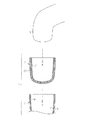
以下、図3を参照して、本発明に係る義肢用ライナーを、下腿部において切断された足の断端部Sに装着される義足用ライナー(以下、「ライナー102」)として具体化した第2実施形態について説明する。
(4) The liner 2 is formed of a rubber cloth. Thereby, even if the shape of the user's stump S changes to some extent, the elastic deformation of the liner 2 between the stump S and the inner surface of the
Second Embodiment
Hereinafter, referring to FIG. 3, the liner for prosthetic limbs according to the present invention is embodied as a liner for prosthetic limbs (hereinafter referred to as “
図3に、本実施形態のライナー102について、同ライナー102を中心とした部分断面構造を模式的に示す。尚、同図は、ライナー102が装着された足の断端部Sがソケット103の挿嵌部104に挿嵌されている状態を示している。また、便宜上、断端部Sとライナー102とを、またライナー102とソケット103の挿嵌部104とを、それぞれ離間して示しているが、実際には、これらはそれぞれ接触した状態となっている。また、第1実施形態において例示した構成と同一の構成(例えば符号「2」が付される構成)については対応する符号として「100」を加算した符号(例えば「102」)を付すことにより重複する説明を割愛する。
FIG. 3 schematically shows a partial cross-sectional structure around the
以下、第1実施形態との相違点を中心に説明する。
図3に示すように、ライナー102は、先の第1実施形態において例示したライナー2と同一の構成である。
Hereinafter, the difference from the first embodiment will be mainly described.
As illustrated in FIG. 3, the
一方、ソケット103には、その挿嵌部104の内側面に、先の第1実施形態において例示した繊維状部材41が設けられていない。すなわち、ソケット103の挿嵌部104の内側面は、ソケット103を構成する繊維強化樹脂によって形成される素面が露出している。
On the other hand, the
次に、本実施形態の作用について説明する。
ライナー102に対して断端部Sを挿入する場合には、ライナー102の内側面に設けられた繊維状部材121が順毛となるため、その挿入に際して生じる抵抗力は小さい。このため、ライナー102の内側面に繊維状部材121を設けることに起因してライナー102の装着が困難なものとなることはない。また、ソケット103の挿嵌部104に対してライナー102が装着された断端部Sを挿入する場合には、ライナー102の外側面に設けられた繊維状部材122が順毛となるため、その挿入に際して生じる抵抗力は小さい。このため、ライナー102の外側面に繊維状部材122を設けることに起因してソケットの装着が困難なものとなることはない。
Next, the operation of this embodiment will be described.
When the stump S is inserted into the
一方、ライナー102が断端部Sから抜け落ちようとする場合には、ライナー102の内側面に設けられた繊維状部材121が逆毛となるため、大きな抵抗力が生じる。このため、ライナー102が断端部Sから抜け落ちることが抑制されるようになる。また、ライナー102の装着された断端部S、すなわちライナー102によって被覆された断端部Sからソケット103が抜け落ちようとする場合には、ライナー102の外側面に設けられた繊維状部材122が逆毛となるため、大きな抵抗力が生じる。このため、ライナー102の装着された断端部Sからソケット103が抜け落ちることが抑制されるようになる。
On the other hand, when the
以上説明した本実施形態に係る義肢用ライナーによれば、第1実施形態の作用効果(4)に加えて、以下に示す作用効果が得られるようになる。
(5)ライナー102は、足の断端部Sに装着された状態でソケット103に挿嵌されるものであって、ライナー102の内側面には、ライナー102に断端部Sを挿入する方向Aに傾斜する起毛である繊維状部材121が設けられるものとした。これにより、容易な装着作業を通じて足の断端部Sにライナー102を装着することができるとともに、ライナー102が断端部Sから抜け落ちることを簡易な構成をもって抑制することができ、ライナー102の正常な装着状態を維持することができるようになる。また、シリコン樹脂等の材料によって形成されるライナーを用いてライナーと断端部Sとの密着性を高くしなくとも、ライナー102が断端部Sから抜け落ちることを抑制することができることから、長時間の使用によって断端部Sとライナー102との間に蒸れが生じることはなく、使用者に不快感を与えることはない。また、ソケット103とライナー102とが密着することがないことから、ソケット103とライナー102との間の内部空間が密閉状態とされることがなく、不快な音が発生することもない。
According to the liner for prosthetic limbs which concerns on this embodiment demonstrated above, in addition to the effect (4) of 1st Embodiment, the effect shown below comes to be obtained.
(5) The
(6)ライナー102の外側面には、ソケット103の挿嵌部104にライナー102を挿入する方向Aとは逆の方向に傾斜する起毛である繊維状部材122が設けられるものとした。これにより、容易な装着作業を通じて足の断端部Sにソケット103を装着することができるとともに、ソケット103が断端部Sから抜け落ちることを簡易な構成をもって抑制することができ、ソケット103の正常な装着状態を維持することができるようになる。
<第3実施形態>
以下、図4を参照して、本発明に係る義肢を、下腿部において切断された足の断端部Sに装着される義足201として具体化した第3実施形態について説明する。
(6) The outer surface of the
<Third Embodiment>
Hereinafter, with reference to FIG. 4, a third embodiment in which a prosthetic limb according to the present invention is embodied as a
図4に、本実施形態の義足201について、同義足201を中心とした一部断面構造を模式的に示す。尚、同図は、足の断端部Sに義足201が装着された状態を示している。また、便宜上、断端部Sとソケット203とを離間して示しているが、実際には、これらは接触した状態となっている。
In FIG. 4, the partial cross-section structure centering on the
同図に示すように、ソケット203の底部には、ソケット203の底面から下方に突出する凸部を有する金属製のソケット側連結部244が内設されている。このソケット側連結部244の凸部は、足部209及び管部208に連結される連結部207において同連結部207の上部に形成される凹部に挿入されて係合されるようになっている。
As shown in the figure, at the bottom of the
本実施形態では、ソケット203の挿嵌部204の内側面に、以下に詳述する繊維状部材241を設けることにより、足の断端部Sからソケット203が抜け落ちることを抑制するようにしている。すなわち、繊維状部材241は、ソケット203の挿嵌部204に断端部Sを挿入する方向に傾斜する起毛であり、ソケット203の挿嵌部204の内側面全体に形成されている。
In this embodiment, the
次に、本実施形態の作用について説明する。
ソケット203の挿嵌部204に対して断端部Sを挿入する場合には、繊維状部材241が順毛となるため、その挿入に際して生じる抵抗力は小さい。このため、ソケット203の内側面に繊維状部材241を設けることに起因してソケット203の装着が困難なものとなることはない。
Next, the operation of this embodiment will be described.
When the cut end portion S is inserted into the
一方、ソケット203が断端部Sから抜け落ちようとする場合には、繊維状部材241が逆毛となるため、大きな抵抗力が生じる。このため、ソケット203が断端部Sから抜け落ちることが抑制されるようになる。
On the other hand, when the
以上説明した本実施形態に係る義肢によれば、以下に示す作用効果が得られるようになる。
(7)義足201は、足の断端部Sを挿嵌可能な挿嵌部204を有したソケット203を備えるものであって、ソケット203の内側面には、ソケット203の挿嵌部204に断端部Sを挿入する方向に傾斜する起毛である繊維状部材241が設けられるものとした。これにより、容易な装着作業を通じて足の断端部Sに義足201を装着することができるとともに、義足201が断端部Sから抜け落ちることを簡易な構成をもって抑制することができ、義足201の正常な装着状態を維持することができるようになる。
<第4実施形態>
以下、図5を参照して、本発明に係る義足を、下腿部において切断された足の断端部Sに装着される義足301として具体化した第4実施形態について説明する。
According to the artificial limb according to the present embodiment described above, the following operational effects can be obtained.
(7) The
<Fourth embodiment>
Hereinafter, with reference to FIG. 5, 4th Embodiment which actualized the artificial leg which concerns on this invention as the
図5に、本実施形態の義足301について、同義足301を中心とした部分断面構造を模式的に示す。尚、同図は、足の断端部Sに義足301が装着された状態を示している。また、便宜上、断端部Sとソケット303とを離間して示しているが、実際には、これらは接触した状態となっている。
FIG. 5 schematically shows a partial cross-sectional structure of the
同図に示すように、ソケット303は、有底筒状をなすとともに繊維強化樹脂によって形成されるソケット本体303Aと、袋状をなすとともにソケット本体303Aの内側面に貼り付けられるライナー部303Bとを備えている。ここで、ライナー部303Bは、上記第1実施形態において例示したライナー2を形成するゴム生地と同じ材料によって形成されている。このように、本実施形態では、ソケット本体303Aとライナー部303Bとが一体化されている。以下では、ソケット本体303Aの内側面に貼り付けられたライナー部303Bの内側面を、「ソケット303の内側面」として説明する。
As shown in the figure, the
本実施形態では、ソケット303の挿嵌部304の内側面に、以下に詳述する繊維状部材341を設けることにより、足の断端部Sからソケット303が抜け落ちることを抑制するようにしている。
In this embodiment, the
すなわち、繊維状部材341は、ソケット303の挿嵌部304に断端部Sを挿入する方向Aに傾斜する起毛であり、ソケット303の挿嵌部304の内側面全体に形成されている。
That is, the
次に、本実施形態の作用について説明する。
ソケット303の挿嵌部304に対して断端部Sを挿入する場合には、繊維状部材341が順毛となるため、その挿入に際して生じる抵抗力は小さい。このため、ソケット303の内側面に繊維状部材341を設けることに起因してソケット303の装着が困難なものとなることはない。
Next, the operation of this embodiment will be described.
When the cut end portion S is inserted into the
一方、ソケット303が断端部Sから抜け落ちようとする場合には、繊維状部材341が逆毛となるため、大きな抵抗力が生じる。このため、ソケット303が断端部Sから抜け落ちることが抑制されるようになる。
On the other hand, when the
以上説明した本実施形態に係る義肢によれば、上記第3実施形態の作用効果(7)に準じた作用効果が得られるようになる。
<第5実施形態>
以下、図6〜図8を参照して、本発明に係る義肢を、下腿部において切断された足の断端部Sに装着される義足401として具体化した第5実施形態について説明する。
According to the prosthetic limb according to the present embodiment described above, an effect similar to the effect (7) of the third embodiment can be obtained.
<Fifth Embodiment>
Hereinafter, with reference to FIGS. 6-8, 5th Embodiment which actualized the artificial leg which concerns on this invention as the
図6に、本実施形態の義足401の概略構成を示す。尚、同図においては、義足401を構成するライナー402の側面構造とソケット403の部分断面構造とを同軸状に離間した状態で示している。また、第1実施形態において例示した構成と同一の構成(例えば符号「2」が付される構成)については対応する符号として「400」を加算した符号(例えば「402」)を付すことにより重複する説明を割愛する。
In FIG. 6, schematic structure of the
以下、第1実施形態との相違点を中心に説明する。
本実施形態では、ライナー402の外側面及びソケット403の挿嵌部404の内側面に、以下の繊維状部材423、424、443、444を設けることにより、ソケット403が同ソケット403の周方向(ライナー402の周方向)X,Yに回動することを抑制するようにしている。
Hereinafter, the difference from the first embodiment will be mainly described.
In the present embodiment, the following
同図に示すように、本実施形態では、ライナー402の外側面において同ライナー402の開口部側(同図中において上側)に、第1繊維状部材423が設けられている。また、ライナー402の外側面において同ライナー402の先端部側(同図中において下側)に、第2繊維状部材424が設けられている。これら繊維状部材423、424は、ライナー402の外側面全周にわたり所定の幅をもって形成されている。
As shown in the figure, in the present embodiment, a first
また、ソケット403の挿嵌部404の内側面において同挿嵌部404の開口部側(同図中において上側)に、第2繊維状部材443が設けられている。また、ソケット403の挿嵌部404の内側面において同挿嵌部404の底部側(同図中において下側)に、第1繊維状部材444が設けられている。これら繊維状部材443、444は、ソケット403の挿嵌部404の内側面全周にわたり所定の幅をもって設けられている。
Further, a second
次に、図7及び図8を参照して、ライナー402の外側面及びソケット403の挿嵌部404の内側面に設けられる繊維状部材423、424、443、444について詳細に説明する。
Next, the
図7に、ライナー402の装着された断端部Sがソケット403の挿嵌部404に挿嵌された状態における義足401の横断面構造であって、繊維状部材423、443の配設位置における横断面構造を示す。また図8に、ライナー402の装着された断端部Sがソケット403の挿嵌部404に挿嵌された状態における義足401の横断面構造であって、繊維状部材424、444の配設位置における横断面構造を示す。尚、これらの図においては、便宜上、ライナー402とソケット403とを離間して示しているが、実際には、これらはそれぞれ接触した状態となっている。
FIG. 7 shows a cross-sectional structure of the
図7に示すように、ライナー402の外側面に設けられる第1繊維状部材423は、同ライナー402の周方向において、すなわち同ライナー402の外側面に沿って周回する方向において所定の方向Xに傾斜する起毛である。一方、ソケット403の内側面に設けられる第2繊維状部材443は、同ソケット403の周方向において上記所定の方向Xとは逆の方向Yに傾斜する起毛である。
As shown in FIG. 7, the first
図8に示すように、ライナー402の外側面に設けられる第2繊維状部材424は、同ライナー402の周方向において所定の方向Xに傾斜する起毛である。一方、ソケット403の内側面に設けられる第1繊維状部材444は、同ソケット403の周方向において上記所定の方向Xに傾斜する起毛である。
As shown in FIG. 8, the second
尚、これら図7、8では、便宜上、各繊維状部材423、424、443、444の起毛を誇張して記載している。
次に、図7及び図8を参照して、本実施形態の作用について説明する。
In FIGS. 7 and 8, the raised portions of the
Next, with reference to FIG.7 and FIG.8, the effect | action of this embodiment is demonstrated.
図7に示すように、ライナー402の装着された足の断端部Sがソケット403の挿嵌部404に挿嵌された状態において、ソケット403が、同ソケット403の周方向において所定の方向Xとは逆の方向Yに回転しようとする場合には、同ソケット403の内側面に設けられた第2繊維状部材443が逆毛となり、またライナー402の外側面に設けられた第1繊維状部材423が逆毛となる。そしてそれら繊維状部材443、423の傾斜方向が逆方向となっているためにそれらが絡み合うことで、大きな抵抗力が生じる。このため、ソケット403が、同ソケット403の周方向において上記所定の方向Xとは逆の方向Yに回転することが抑制されるようになる。
As shown in FIG. 7, in a state where the stump portion S of the foot to which the
図8に示すように、ライナー402の装着された足の断端部Sがソケット403の挿嵌部404に挿嵌された状態において、ソケット403が、上記所定の方向Xに回転しようとする場合には、同ソケット403の内側面に設けられた第1繊維状部材444が逆毛となり、またライナー402の外側面に設けられた第2繊維状部材424が逆毛となる。そしてそれら繊維状部材の傾斜方向が逆方向となっているためにそれらが絡み合うことで、大きな抵抗力が生じる。このため、ソケット403が、同ソケット403の周方向において上記所定の方向Xに回転することが抑制されるようになる。
As shown in FIG. 8, when the
このようにして、ソケット403が、同ソケット403の周方向において所定の方向Xに回転する場合であれ、同所定の方向Xとは逆の方向Yに回転する場合であれ、ソケット403の内側面及びライナー402の外側面に設けられた各繊維状部材443、444、423、424のうち対応する繊維状部材443、423(444、424)が絡み合うようになるため、上記所定の方向Xの回転及びその逆の方向Yの回転の双方が抑制されるようになる。すなわち、ソケット403がその周方向に回動することが抑制されるようになる。
In this way, whether the
以上説明した本実施形態に係る義肢によれば、以下に示す作用効果が得られるようになる。
(8)義足401は、足の断端部Sが挿嵌される挿嵌部404を有したソケット403を備えるものであって、ソケット403の内側面には、同ソケット403の周方向において所定の方向Yに傾斜する第1繊維状部材444と、同所定の方向Xとは逆の方向Yに傾斜する第2繊維状部材443とが設けられるものとした。これにより、容易な装着作業を通じて足の断端部Sに義足401を装着することができるとともに、義足401が断端部Sに対して回転することを簡易な構成をもって抑制することができ、義足401の正常な装着状態を維持することができるようになる。
According to the artificial limb according to the present embodiment described above, the following operational effects can be obtained.
(8) The
(9)義足401は、断端部Sに装着されるライナー402を備え、ソケット403の挿嵌部404にはライナー402が装着された断端部Sが挿嵌されるものとした。また、ライナー402の外側面には、同ライナー402の周方向において所定の方向Xに傾斜する第1繊維状部材423と、同所定の方向Xとは逆の方向Yに傾斜する起毛を有した第2繊維状部材424とが設けられるものとした。これにより、容易な装着作業を通じて足の断端部Sに義足401を装着することができるとともに、義足401が断端部に対して回転することを簡易な構成をもって的確に抑制することができ、義足401の正常な装着状態を好適に維持することができるようになる。
(9) The
(10)ライナー402の装着された足の断端部Sがソケット403の挿嵌部404に挿嵌された状態で、ソケット403の内側面に設けられた第2繊維状部材443と、ライナー402の外側面に設けられる第1繊維状部材423とを互いに接触するように構成し、且つそれら接触する繊維状部材443、423の傾斜方向が逆方向となるように構成した。また、ソケット403の内側面に設けられる第1繊維状部材444と、ライナー402の外側面に設けられる第2繊維状部材424とを互いに接触するように構成し、且つそれら接触する繊維状部材444、424の傾斜方向が逆方向となるように構成した。これにより、容易な装着作業を通じて足の断端部Sに義足401を装着することができるとともに、義足401が断端部Sに対して回転することを簡易な構成をもって一層的確に抑制することができ、義足401の正常な装着状態を一層的確に維持することができるようになる。
<第6実施形態>
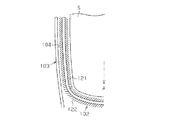
以下、図9及び図10を参照して、本発明に係る義肢を、下腿部において切断された足の断端部Sに装着される義足501として具体化した第6実施形態について説明する。
(10) The second
<Sixth Embodiment>
Hereinafter, with reference to FIG.9 and FIG.10, 6th Embodiment which actualized the artificial leg which concerns on this invention as the
図9(a)、(b)に、本実施形態の義足501の概略構成を示す。尚、同図(a)は、義足501を中心とした正面構造を示したものであり、同図(b)は、ソケット503の断面構造を示したものである。また、同図中において、膝を「K」にて示している。また、図10に、図9のE−E断面構造を示す。
9A and 9B show a schematic configuration of the
尚、これら図9及び図10では、第1実施形態において例示した構成と同一の構成(例えば符号「2」が付される構成)については対応する符号として「500」を加算した符号(例えば「502」)を付すことにより重複する説明を割愛する。 In FIGS. 9 and 10, the same configuration as the configuration exemplified in the first embodiment (for example, the configuration with the symbol “2”) is added by adding “500” as the corresponding code (for example, “ 502 ”) will be omitted to avoid redundant explanation.
以下、第1実施形態との相違点を中心に説明する。
図9に示すように、ソケット503は、下腿の断端部Sが挿嵌可能なものであり、その挿嵌部504における入口部分505が使用者の膝下に位置する。
Hereinafter, the difference from the first embodiment will be mainly described.
As shown in FIG. 9, the
ところで、大腿の断端部が挿嵌されるソケットにあっては(図示略)、通常、ソケットの座骨支持面が使用者の体重を支持する形状とされていることから、ソケットの挿嵌部の奥への断端部の落ち込みがある程度規制されるようになっている。これに対して、図9(a)に示すように、下腿の断端部Sが挿嵌されるソケット503にあっては、大腿用ソケットのように体重を支持する部位が少ないことから、ソケット503の挿嵌部504の奥に断端部Sが落ち込むといった問題が生じやすい。特に、ソケット503が、下腿の断端部Sが挿嵌されるものにあっては、使用者の足が痩せ細る等して、膝下と、これに対向するソケット503の内側面との間の間隙が大きくなると、ソケット503を通じて使用者の体重を好適に支持することができなくなり、ソケット503の挿嵌部504の奥に断端部Sが落ち込みやすくなる。
By the way, in the socket into which the stump portion of the thigh is inserted (not shown), since the socket supporting surface of the socket is usually shaped to support the weight of the user, the insertion portion of the socket The fall of the stump portion to the back of the head is regulated to some extent. On the other hand, as shown in FIG. 9 (a), the
そこで、本実施形態では、図9(b)及び図10に併せ示すように、ソケット503の内側面に、より具体的には、その膝下に位置する部位を含む内側面に、同ソケット503の挿嵌部504に断端部Sを挿入する方向Aとは逆の方向に傾斜する繊維状部材545を設けるようにしている。ここで、繊維状部材545が設けられる部位には、体重支持部が含まれている。尚、ソケット503の内側面において繊維状部材545が設けられている部位以外の部位には、先の第1実施形態において例示した繊維状部材41と同一の繊維状部材541が設けられている。
Therefore, in the present embodiment, as shown in FIGS. 9B and 10, the
また、図10に示すように、ライナー502の外側面においてソケット503の内側面に設けられる繊維状部材545に対向する位置には、ソケット503の挿嵌部504にライナー502を挿入する方向Aに傾斜する繊維状部材525を設けるようにしている。尚、ライナー502の外側面において繊維状部材525が設けられている部位以外の部位には、先の第1実施形態において例示した繊維状部材22と同一の繊維状部材522が設けられている。また、ライナー502の内側面には、先の第1実施形態において例示した繊維状部材21と同一の繊維状部材521が設けられている。
Further, as shown in FIG. 10, the outer surface of the
以下、本実施形態の作用を説明する。
図10に示すように、ライナー502の装着された断端部Sがソケット503の挿嵌部504に完全に挿嵌されている状態において、ソケット503の挿嵌部504の奥に断端部Sが落ち込もうとする場合には、ソケット503の内側面の体重支持部に設けられた繊維状部材545の逆毛となり、またライナー502の外側面に設けられた繊維状部材525が逆毛となる。そして、それら繊維状部材545、525の傾斜方向が逆方向となっているためにそれらが互いに絡み合うことで、大きな抵抗力が生じる。このため、ソケット503の挿嵌部504の奥に断端部Sが落ち込むことが抑制されるようになる。
Hereinafter, the operation of the present embodiment will be described.
As shown in FIG. 10, in the state where the cut end portion S to which the
ここで、ソケット503の挿嵌部504は、その入口部分505がその他の部分よりも大きな径を有しているため、ソケット503の装着時において、ライナー502の外側面においてソケット503の内側面に対向する位置に設けられた繊維状部材525は逆毛になりにくく、またソケット503の内側面に設けられた繊維状部材545は逆毛になりにくい。そのため、ソケット503の装着が困難なものとなることはない。すなわち、ソケット503の挿嵌部504に断端部Sが完全に挿嵌された状態で更に断端部Sが落ち込もうとする場合に、これら繊維状部材525、545が逆毛となって上述したような落ち込みの抑制機能が作用することとなる。
Here, the
以上説明した本実施形態に係る義肢によれば、第1実施形態の作用効果(1)〜(4)に加えて、以下に示す作用効果が得られるようになる。
(11)ソケット503の内側面には、同ソケット503の挿嵌部504に断端部Sを挿入する方向Aとは逆の方向に傾斜する繊維状部材545が設けられるものとした。これにより、容易な装着作業を通じて足の断端部Sに義足501を装着することができるとともに、ソケット503の挿嵌部504の奥に断端部Sが落ち込むことを簡易な構成をもって抑制することができ、義足501の正常な装着状態を維持することができるようになる。
According to the prosthetic limb according to the present embodiment described above, the following effects can be obtained in addition to the effects (1) to (4) of the first embodiment.
(11) On the inner surface of the
(12)ソケット503は、下腿の断端部Sが挿嵌されるものであって、ソケット503は、その挿嵌部504における入口部分505が膝下に位置するものであり、繊維状部材545はその膝下に位置する部位の内側面、すなわち体重支持部に設けられるものとした。これにより、ソケット503の挿嵌部504の奥に断端部Sが落ち込むことを的確に抑制することができるようになる。
(12) The
(13)義足501は、断端部Sに装着されるライナー502を備えるものとした。また、ソケット503はその挿嵌部504にライナー502が装着された断端部Sが挿嵌されるものであり、ライナー502の外側面においてソケット503の内側面に設けられる繊維状部材545に対向する位置には、ソケット503の挿嵌部504にライナー502を挿入する方向Aに傾斜する繊維状部材525が設けられるものとした。これにより、ソケット503の挿嵌部504の奥に断端部Sが落ち込むことを一層抑制することができるようになる。
(13) The
尚、本発明に係る義肢及び義肢用ライナーは、上記実施形態にて例示した構成に限定されるものではなく、これを適宜変更した例えば次のような形態として実施することもできる。 In addition, the prosthetic limb and the prosthetic limb liner according to the present invention are not limited to the configuration exemplified in the above-described embodiment, and can be implemented as, for example, the following forms appropriately modified.
・上記第1実施形態では、有底筒状のソケット3について例示したが、これに代えて、底なしの筒状のソケットとしてもよい。
・上記各実施形態では、厚さが2mm〜5mmのゴム生地によってライナーを構成するようにしているが、ライナーの厚さはこれに限られるものではなく、他に例えば、ライナーが使用される環境、特に気温や湿度等に応じて、5mm以上の厚さを有するゴム生地や2mm未満の厚さを有するゴム生地に変更することもできる。
In the first embodiment, the bottomed
In each of the above embodiments, the liner is made of rubber fabric having a thickness of 2 mm to 5 mm. However, the thickness of the liner is not limited to this, and for example, an environment where the liner is used. In particular, it can be changed to a rubber fabric having a thickness of 5 mm or more or a rubber fabric having a thickness of less than 2 mm, depending on the temperature, humidity and the like.
・上記各実施形態では、ゴム生地によってライナーを形成するようにしているが、ライナーの材料はこれに限られるものではなく、他に例えば織布や不織布といった他の材料によって形成することもできる。 In each of the above embodiments, the liner is formed from the rubber cloth, but the material of the liner is not limited to this, and can be formed from other materials such as a woven fabric and a non-woven fabric.
・上記各実施形態においては、繊維状部材を直毛のものについてのみ例示したが、繊維状部材の形状はこれに限られるものではなく、他に例えば、湾曲したものや、螺旋状のものであってもよい。こうした繊維状部材としては、その毛根から毛先にかけて全体として、上記各実施形態において例示した所定の方向に傾斜しているものであればよい。 In each of the above embodiments, the fibrous member is exemplified only for straight hair, but the shape of the fibrous member is not limited to this, and for example, it may be curved or spiral. There may be. As such a fibrous member, what is necessary is just to incline in the predetermined direction illustrated in each said embodiment as a whole from the hair root to the hair tip.
・上記第1実施形態では、ゴム生地の縫着によってライナー2を形成していることから、ライナー2の内側面に繊維状部材21が設けられることに加え、ライナー2の底面にも繊維状部材21が設けられるようになっている。しかしながら、本発明に係る繊維状部材は、必ずしもライナーの底面に設けられる必要はなく、これに代えて、図11に示すように、ライナー602の内側面にのみ繊維状部材621を設け、ライナー602の底面についてはシリコン樹脂等、伸縮性や弾力性に富む材料によって形成されるスペーサ605を設けるようにしてもよい。これにより、断端部Sの先端とスペーサ605とが密着した状態に維持されることから、使用者の動きによってライナー602の底面と断端部Sの先端面とが離れること、及びこのことに起因する不快な音の発生を抑制することができるようになる。
In the first embodiment, since the liner 2 is formed by sewing rubber fabric, the
・上記第1実施形態では、繊維状部材21、22、41をライナー2の内側面の一部分、外側面の一部分、或いはソケット3の内側面の一部分に繊維状部材を設けるようにしているが、これらをライナー2の内側面全体、ライナー2の外側面全体、及びソケット3の内側面全体に設けるようにしてもよい。
In the first embodiment, the
・上記第1実施形態によるように、ライナー2の外側面に繊維状部材22を設けることが、こうした繊維状部材22と、ソケット3の内側面に設けられた繊維状部材41とを互いに絡み合わせて、ライナー2の装着された断端部Sからソケット3が抜け落ちることを的確に抑制する上では望ましい。しかしながら、本発明に係る義肢及び義肢用ライナーはこれに限られるものではなく、例えば義足が比較的軽い場合のように、ライナーの装着された断端部Sからソケットが抜け落ちることを抑制する上で必要とされる抵抗力がそれほど大きくない場合であれば、図12に示す義足701及びライナー702のように、ライナー702の内側面にのみ繊維状部材721を設け、ライナー702の外側面については繊維状部材を設けないようにしてもよい。この場合であっても、ソケット703の内側面に設けられた繊維状部材741によって、ライナー702の装着された断端部Sからソケット703が抜け落ちようとすることを、ある程度は抑制することができるようになる。
As described in the first embodiment, providing the
・上記第1実施形態によるように、ライナー2の内側面に繊維状部材21を設けることが、足の断端部Sからライナー2が抜け落ちることを抑制する上では望ましい。しかしながら、本発明に係る義肢及び義肢用ライナーはこれに限られるものではなく、例えばライナーが樹脂によって形成されるものであって、ライナー自身の復元力によって断端部Sから同ライナーが抜け落ちることを抑制することができる場合には、図13に示す義足801及びライナー802のように、ライナー802の外側面に繊維状状留め部材822を設け、ライナー802の内側面には繊維状部材を設けないようにすることもできる。
As described in the first embodiment, it is desirable to provide the
・本発明に係る義肢は、ライナーの内側面及び外側面の少なくとも一方に繊維状部材が設けられるものに限らず、他に例えば、図14に示す義足901のように、ソケット903の挿嵌部904の内側面にのみ繊維状部材941を設け、ライナー902については、その内側面及び外側面の双方に繊維状部材を設けないようにすることもできる。この場合であっても、例えばライナーが樹脂によって形成されるものであって、ライナー自身の復元力によって断端部Sからライナーが抜け落ちることを抑制することができるのであれば、ソケット903の挿嵌部904の内側面に設けられる繊維状部材941によって、ライナー902の装着された断端部Sからソケット903が抜け落ちることを、ある程度は抑制することができるようになる。
The prosthetic limb according to the present invention is not limited to the one in which the fibrous member is provided on at least one of the inner side surface and the outer side surface of the liner, but, for example, like the
・上記第2実施形態によるように、ライナー102の内側面に繊維状部材121を設けることが、足の断端部Sからライナー102が抜け落ちることを抑制する上では望ましい。しかしながら、本発明に係る義肢用ライナーはこれに限られるものではなく、例えばライナーが樹脂によって形成されるものであって、ライナー自身の復元力によって断端部Sからライナーが抜け落ちることを抑制することができる場合には、図15に示すライナー1002のように、その内側面に繊維状部材を設けないようにすることもできる。すなわち、ライナー1002の外側面にのみ繊維状状留め部材1022を設けるようにしてもよい。この場合であっても、ライナー1002の外側面に設けられる繊維状部材1022によって、断端部Sからソケット1003が抜け落ちることを、ある程度は抑制することができるようになる。
As described in the second embodiment, it is desirable to provide the
・上記第5実施形態では、繊維状部材423、424、443、444を、ソケット403の周方向(ライナー402の周方向)において全周にわたって設けるようにしているが、これらを、ソケット403の周方向において部分的に設けるようにしてもよい。
In the fifth embodiment, the
・上記第5実施形態によるように、ライナー402の装着された足の断端部Sがソケット403の挿嵌部404に挿嵌された状態で、ソケット403の内側面に設けられる繊維状部材443、444とライナー402の外側面に設けられる繊維状部材423、424とを互いに接触するように構成し、且つそれら接触する繊維状部材443、423(444、424)の傾斜方向が逆方向となるように構成することが、ソケット403が同ソケット403の周方向に回動することを的確に抑制する上では望ましい。しかしながら、本発明に係る義肢はこれに限られるものではなく、上記第5実施形態において、ソケット403の内側面に設けられる第1繊維状部材444及び第2繊維状部材443のいずれか一方を割愛するようにすることや、第1繊維状部材444及び第2繊維状部材443のいずれか一方を、ライナー402の外側面に設けられる第2繊維状部材424及び第1繊維状部材423に接触しない位置に設けるようにすることもできる。また、上記第5実施形態において、ライナー402の外側面に設けられる第1繊維状部材423及び第2繊維状部材424のいずれか一方を割愛するようにすることもできる。更に、ソケット403の挿嵌部404の内側面に設けられる繊維状部材444、443とライナー402の外側面に設けられる繊維状部材423、424とが互いに接触しないように構成することもできる。
As in the fifth embodiment, the
・上記第5実施形態では、ソケット403の内側面及びライナー402の外側面の双方に、繊維状部材443、444、423、424を設けるようにしているが、本発明に係る義肢はこれに限られるものではなく、ライナーの外側面に繊維状部材を設けないようにすることもできる。すなわち、ソケットの内側面にのみ繊維状部材が設けられるものであっても、断端部Sに対して義足が回動することをある程度は抑制することができるようになる。また、これとは反対に、ソケットの内側面に繊維状部材を設けないようにすることもできる。すなわち、ライナーの外側面にのみ繊維状部材が設けられるものであっても、断端部Sに対して義肢が回動することをある程度は抑制することができるようになる。
In the fifth embodiment, the
・上記第5実施形態では、ソケット403の内側面に、同ソケット403の周方向において所定の方向Xに傾斜する第1繊維状部材444と、同所定の方向Xとは逆の方向Yに傾斜する第2繊維状部材443とを設けるようにしている。しかしながら、これに代えて、ソケットの内側面に、第1繊維状部材444及び第2繊維状部材443のいずれか一方のみを設けるようにすることもできる。
In the fifth embodiment, the first
・上記第5実施形態では、ライナー402の外側面に、同ライナー402の周方向において所定の方向Xに傾斜する第1繊維状部材423と、同所定の方向Xとは逆の方向Yに傾斜する第2繊維状部材424とを設けるようにしている。しかしながら、これに代えて、ライナーの外側面に、第1繊維状部材423及び第2繊維状部材424のいずれか一方のみを設けるようにすることもできる。
In the fifth embodiment, the first
・上記第6実施形態では、図9(b)に示すように、ソケット503は、その挿嵌部504における入口部分505が膝下に位置するものであり、その膝下に位置する部位の内側面にのみ繊維状部材545を設けるようにしているが、これに代えて、こうした繊維状部材をソケットの挿嵌部における入口部分の内周面全周に設けるようにしてもよい。
-In the said 6th Embodiment, as shown in FIG.9 (b), as for the
・上記第6実施形態によるように、ライナー502の外側面に、ソケット503の挿嵌部504にライナー502を挿入する方向Aに傾斜する起毛を有した繊維状部材525を設けることが、ライナー502の外側面に設けられた繊維状部材525の起毛と、ソケット503の内側面に設けられた繊維状部材545とを絡み合わせて、ソケット503の挿嵌部504の奥に断端部Sが落ち込むことを抑制する上では望ましい。しかしながら、本発明はこれに限られるものではなく、これに代えて、ライナー502の外側面に設けられた繊維状部材525を割愛するようにしてもよい。この場合であっても、ライナー502の装着された断端部Sがソケット503の挿嵌部504に完全に挿嵌されている状態において、ソケット503の挿嵌部504の奥に断端部Sが落ち込もうとする場合に、ソケット503の内側面に設けられた繊維状部材545が逆毛となることで、大きな抵抗力が生じることから、ソケット503の挿嵌部504の奥に断端部Sが落ち込むことが、ある程度は抑制されるようになる。
As described in the sixth embodiment, it is possible to provide the
・上記第6実施形態において、ソケット503の内側面に設けられた繊維状部材545を割愛するようにしてもよい。この場合であっても、ライナー502の外側面に設けられた繊維状部材525が逆毛となることで、大きな抵抗力が生じることから、ソケット503の挿嵌部504の奥に断端部Sが落ち込むことが、ある程度は抑制されるようになる。
In the sixth embodiment, the
・上記第6実施形態によるように、ソケットの内側面に、繊維状部材545の他に、繊維状部材541を設けるようにすることが、ソケット503の挿嵌部504の奥に断端部Sが落ち込むことを抑制するとともに、ソケット503が断端部Sから抜け落ちることを抑制する上では望ましい。しかしながら、本発明はこれに限られるものではなく、ライナーの装着された断端部からのソケットの抜け落ちが問題とならないのであれば、上記繊維状部材541を割愛するようにしてもよい。
As described in the sixth embodiment, in addition to the
・上記第6実施形態によるように、ライナーの外側面に、繊維状部材525の他に、繊維状部材522を設けるようにすることが、ソケット503の挿嵌部504の奥に断端部Sが落ち込むことを抑制するとともに、ソケット503が断端部Sから抜け落ちることを抑制する上では望ましい。しかしながら、本発明はこれに限られるものではなく、ライナーの装着された断端部からのソケットの抜け落ちが問題とならないのであれば、上記繊維状部材522を割愛するようにしてもよい。
As described in the sixth embodiment, it is possible to provide the
・上記第6実施形態では、ソケット503の内側面においてその入口部分505に繊維状部材545を設けるようにしている。また、ライナー502の外側面においてこうした繊維状部材545に対向するように繊維状部材525を設けるようにしている。しかしながら、本発明はこれに限られるものではなく、ソケットの内側面においてその奥部分に繊維状部材を設けるようにすることもできる。またこの場合、ライナーの外側面においてこうした繊維状部材に対向するように繊維状部材を設けるようにすればよい。
In the sixth embodiment, the
・上記第6実施形態では、下腿の断端部が挿嵌されるソケット503を備える義足501について例示したが、本発明はこれに限られるものではなく、これを大腿の断端部が挿嵌されるソケットを備える義足に対して適用することもできる。
-In the said 6th Embodiment, although illustrated about the
・上記第1実施形態及び第6実施形態では、ソケット3、503の内側面に、ソケット3、503の挿嵌部4、504に断端部Sを挿入する方向Bに傾斜する繊維状部材41、541を設けるものについて例示したが、これに加えて、上記第5実施形態において例示した繊維状部材444、443を設けるようにすることもできる。すなわち、ソケットの内側面に、ソケットの挿嵌部に断端部Sを挿入する方向に傾斜する繊維状部材と、ソケットの周方向において所定の方向に傾斜する起毛を有した繊維状部材との双方を設けるようにしてもよい。
-In the said 1st Embodiment and 6th Embodiment, the
・上記第1実施形態及び第6実施形態では、ライナー2、502の外側面に、ソケット3、503の挿嵌部4、504にライナー2、502を挿入する方向Bとは逆の方向に傾斜する繊維状部材22、522を設けるものについて例示したが、これに加えて、上記第5実施形態において例示した繊維状部材423、424を設けるようにすることもできる。すなわち、ライナーの外側面に、ソケットの挿嵌部にライナーを挿入する方向とは逆の方向に傾斜する繊維状部材と、ライナーの周方向において所定の方向に傾斜する起毛を有した繊維状部材との双方を設けるようにしてもよい。
In the first embodiment and the sixth embodiment, the outer surfaces of the
・上記各実施形態及びその変形例においては、ソケットの内側面に設けられてソケットの挿嵌部に断端部を挿入する方向に傾斜する繊維状部材(以下、繊維状部材K)と、ライナーの外側面に設けられてソケットの挿嵌部にライナーを挿入する方向とは逆の方向に傾斜する繊維状部材(以下、繊維状部材L)とについて例示した。そこでは特に、繊維状部材Kの傾斜方向と、繊維状部材Lの傾斜方向とのなす角度が180°となるものについて例示した。しかしながら、本発明における各繊維状部材はこうした態様を有するものの他、以下に示す態様をもって具現化することもできる。ここで、図16(a)に、繊維状部材Kの傾斜方向と繊維状部材Lの傾斜方向との関係を模式的に示す。同図に示すように、繊維状部材Kの傾斜方向と繊維状部材Lの傾斜方向とのなす角度αが所定角度(90°<α<180°)となるものであればよい。ただし、ソケットが断端部から抜け落ちようとする場合に、これら繊維状部材を逆毛とさせて、大きな抵抗力を生じさせるといった機能を十分に発揮させる上では、この所定角度αを大きく設定することが好ましい。 In each of the above embodiments and modifications thereof, a fibrous member (hereinafter referred to as a fibrous member K) that is provided on the inner surface of the socket and is inclined in a direction in which a stump is inserted into the insertion portion of the socket, and a liner A fibrous member (hereinafter referred to as a fibrous member L) that is provided on the outer surface of the socket and is inclined in a direction opposite to the direction in which the liner is inserted into the insertion portion of the socket is illustrated. In particular, the case where the angle between the inclination direction of the fibrous member K and the inclination direction of the fibrous member L is 180 ° is illustrated. However, each fibrous member in the present invention can be embodied with the following modes in addition to those having such a mode. Here, FIG. 16A schematically shows the relationship between the inclination direction of the fibrous member K and the inclination direction of the fibrous member L. FIG. As shown in the figure, the angle α formed by the inclination direction of the fibrous member K and the inclination direction of the fibrous member L only needs to be a predetermined angle (90 ° <α <180 °). However, when the socket is about to fall off from the cut end portion, the predetermined angle α is set to be large in order to sufficiently exhibit the function of causing these fibrous members to be reversed hairs and generating a large resistance force. It is preferable.
・上記第5実施形態及びその変形例においては、ソケットの内側面に設けられてソケットの周方向において所定の方向に傾斜する第1繊維状部材(以下、第1繊維状部材M)と、上記所定の方向とは逆の方向に傾斜する第2繊維状部材(以下、第2繊維状部材N)とについて例示した。そこでは特に、第1繊維状部材Mの傾斜方向と、第2繊維状部材Nの傾斜方向とのなす角度が180°となるものについて例示した。しかしながら、本発明における各繊維状部材はこうした態様を有するものの他、以下に示す態様をもって具現化することもできる。ここで、図16(b)に、繊維状部材Mの傾斜方向と繊維状部材Nの傾斜方向との関係を模式的に示す。同図に示すように、繊維状部材Mの傾斜方向と繊維状部材Nの傾斜方向とのなす角度βが所定角度(90°<β<180°)となるものであればよい。ただしこの場合も同様に、ソケットが回動しようとする場合に、繊維状部材を逆毛とさせて、大きな抵抗力を生じさせるといった機能を十分に発揮させる上では、この所定角度βを大きく設定することが好ましい。 -In the said 5th Embodiment and its modification, the 1st fibrous member (henceforth 1st fibrous member M) which is provided in the inner surface of a socket and inclines in the predetermined direction in the circumferential direction of a socket, and the said It illustrated about the 2nd fibrous member (henceforth 2nd fibrous member N) inclined in the direction opposite to a predetermined direction. In particular, the case where the angle formed by the inclination direction of the first fibrous member M and the inclination direction of the second fibrous member N is 180 ° is illustrated. However, each fibrous member in the present invention can be embodied with the following modes in addition to those having such a mode. Here, FIG. 16B schematically shows the relationship between the inclination direction of the fibrous member M and the inclination direction of the fibrous member N. As shown in the figure, the angle β formed by the inclination direction of the fibrous member M and the inclination direction of the fibrous member N only needs to be a predetermined angle (90 ° <β <180 °). However, in this case as well, when the socket is about to rotate, the predetermined angle β is set large in order to sufficiently exert the function of causing the fibrous member to be reversed hairs and generating a large resistance force. It is preferable to do.
・上記各実施形態では、下腿部において切断された足に装着される義足及び義足用ライナーについて例示したが、本発明に係る義肢及び義肢用ライナーはこれらに限られるものではなく、大腿部において切断された足のためのものや、義手等のためのものに対して適用することが可能である。 In each of the above-described embodiments, the artificial leg and the artificial leg liner to be worn on the leg cut at the lower leg part are exemplified, but the artificial leg and artificial leg liner according to the present invention are not limited to these, and the thigh part It is possible to apply to those for legs that have been cut in step 1, or for prostheses.
1、201、301、401、501、701、801、901、2001…義足、2、102、202、402、502、602、702、802、902、1002、2002…ライナー、21、121、521、621、721…繊維状部材、22、122、522、622、822、1022…繊維状部材、3、103、203、303、403、503、703、803、903、1003、2003…ソケット、4、104、204、304、404、504、704、804、904、1004、2004…挿嵌部、41、241、341、541、741、841、941…繊維状部材、207…連結部、208…管部、209…足部、244…ソケット側連結部、303A…ソケット本体、303B…ライナー部、423、424、443、444…繊維状部材、525…繊維状部材、505…入口部分、545…繊維状部材、605…スペーサ、2010…装着具、2011…固定片、2012…ベルト、K…膝、S…断端部。 1, 201, 301, 401, 501, 701, 801, 901, 2001 ... Prosthetic leg 2,102,202,402,502,602,702,802,902,1002,2002 ... Liner, 21,121,521 621, 721 ... fibrous member, 22, 122, 522, 622, 822, 1022 ... fibrous member, 3, 103, 203, 303, 403, 503, 703, 803, 903, 1003, 2003 ... socket, 4, 104, 204, 304, 404, 504, 704, 804, 904, 1004, 2004 ... insertion part, 41, 241, 341, 541, 741, 841, 941 ... fibrous member, 207 ... connection part, 208 ... pipe Part, 209 ... foot part, 244 ... socket side connecting part, 303A ... socket body, 303B ... liner part, 423 424, 443, 444 ... fibrous member, 525 ... fibrous member, 505 ... inlet portion, 545 ... fibrous member, 605 ... spacer, 2010 ... mounting tool, 2011 ... fixed piece, 2012 ... belt, K ... knee, S ... stumps.
Claims (5)
前記ライナーの内側面には、前記ライナーに断端部を挿入する方向に傾斜する繊維状部材が貼り付けによって設けられ、
前記ソケットの内側面には、前記ソケットの挿嵌部に断端部を挿入する方向に傾斜する繊維状部材が貼り付けによって設けられる
ことを特徴とする義肢。 A prosthesis comprising a liner attached to a stump portion of a limb, and a socket having an insertion portion into which the stump portion to which the liner is attached can be inserted,
The inner surface of the liner is provided with a fibrous member that is inclined in a direction in which a stump is inserted into the liner,
Wherein the inner surface of the socket, prostheses, characterized in that the fibrous member be inclined in a direction of inserting the cut end portion to the inserting portion of the socket is provided by pasting.
前記ライナーの外側面には、前記ソケットの挿嵌部に前記ライナーを挿入する方向とは逆の方向に傾斜する繊維状部材が設けられる
ことを特徴とする義肢。 The prosthetic limb according to claim 1,
The prosthetic limb , wherein a fibrous member is provided on an outer surface of the liner, and is inclined in a direction opposite to a direction in which the liner is inserted into an insertion portion of the socket .
前記ソケットの内側面には、さらに同ソケットの周方向において所定の方向に傾斜する繊維状部材が設けられ、
前記ライナーの外側面には、さらに同ライナーの周方向において前記所定の方向とは逆の方向に傾斜する繊維状部材が設けられる
ことを特徴とする義肢。 The prosthetic limb according to claim 2,
The inner surface of the socket is further provided with a fibrous member inclined in a predetermined direction in the circumferential direction of the socket,
The prosthetic limb , wherein a fibrous member that is inclined in a direction opposite to the predetermined direction in the circumferential direction of the liner is further provided on the outer surface of the liner .
前記ライナーの装着された手足の断端部が前記ソケットの挿嵌部に挿嵌された状態で、前記ソケットの内側面に設けられた所定の方向に傾斜する繊維状部材と、前記ライナーの外側面に設けられた前記所定の方向とは逆の方向に傾斜する繊維状部材とは、互いに接触するように構成されている
ことを特徴とする義肢。 The prosthetic limb according to claim 3,
A fibrous member which is provided on the inner surface of the socket and is inclined in a predetermined direction with the stumps of the limbs to which the liner is attached inserted into the insertion part of the socket, and an outer side of the liner A prosthetic limb configured to be in contact with each other with fibrous members inclined in a direction opposite to the predetermined direction provided on the side surface .
前記ライナーの内側面の底面には、弾力性を有するスペーサが設けられるAn elastic spacer is provided on the bottom surface of the inner surface of the liner.
ことを特徴とする義肢。Prosthetic limbs characterized by that.
Priority Applications (1)
| Application Number | Priority Date | Filing Date | Title |
|---|---|---|---|
| JP2009254062A JP4964285B2 (en) | 2009-11-05 | 2009-11-05 | Artificial limb |
Applications Claiming Priority (1)
| Application Number | Priority Date | Filing Date | Title |
|---|---|---|---|
| JP2009254062A JP4964285B2 (en) | 2009-11-05 | 2009-11-05 | Artificial limb |
Publications (2)
| Publication Number | Publication Date |
|---|---|
| JP2011098038A JP2011098038A (en) | 2011-05-19 |
| JP4964285B2 true JP4964285B2 (en) | 2012-06-27 |
Family
ID=44189716
Family Applications (1)
| Application Number | Title | Priority Date | Filing Date |
|---|---|---|---|
| JP2009254062A Active JP4964285B2 (en) | 2009-11-05 | 2009-11-05 | Artificial limb |
Country Status (1)
| Country | Link |
|---|---|
| JP (1) | JP4964285B2 (en) |
Family Cites Families (6)
| Publication number | Priority date | Publication date | Assignee | Title |
|---|---|---|---|---|
| JPH07241312A (en) * | 1994-03-04 | 1995-09-19 | Tomio Asai | Eye mask also serving as face mask |
| US6139513A (en) * | 1998-06-02 | 2000-10-31 | Royce Medical Company | Orthopaedic support with hardenable double knit type material |
| EP1052319A1 (en) * | 1999-05-03 | 2000-11-15 | Malden Mills Industries, Inc. | Three-dimensional composite fabric articles |
| US6499320B1 (en) * | 2001-04-03 | 2002-12-31 | Frederick S. Bernhardt | Garment having antimicrobial properties and its associated method of manufacture |
| DE102007035409B4 (en) * | 2007-07-26 | 2010-06-02 | Otto Bock Healthcare Gmbh | Orthopedic interface |
| DE102007035410A1 (en) * | 2007-07-26 | 2009-02-19 | Otto Bock Healthcare Ip Gmbh & Co. Kg | Denture stem for receiving an amputation stump of a limb and system of prosthesis stem and prosthetic device |
-
2009
- 2009-11-05 JP JP2009254062A patent/JP4964285B2/en active Active
Also Published As
| Publication number | Publication date |
|---|---|
| JP2011098038A (en) | 2011-05-19 |
Similar Documents
| Publication | Publication Date | Title |
|---|---|---|
| CN101410073B (en) | Ventilated prosthesis system | |
| US9889024B2 (en) | Cosmetic prosthesis cover | |
| KR101793141B1 (en) | Joint driving module and compliant type robot artificial ankle | |
| US20020183859A1 (en) | Socket interface sleeve for a prosthetic device | |
| US7815688B2 (en) | Lap joint for prosthetic foot | |
| WO2008079272A3 (en) | Prosthetic heart valve including stent structure and tissue leaflets, and related methods | |
| US20100042227A1 (en) | Prosthesis Comprising a Shank for Accommodating an Amputation Stump | |
| CN103930073A (en) | Suspension liner with seal component | |
| US20120095570A1 (en) | Skin-Like Prosthesis Cover Having Substantially Permanently Attached and Releasably Attached Portions | |
| US20160095723A1 (en) | Above-the-knee and below-the-knee prosthetic covers | |
| TW201531288A (en) | Ankle brace | |
| US8413313B2 (en) | Divided-end artificial limb | |
| US20200060846A1 (en) | Liner system and method for applying a liner system | |
| WO2014142643A1 (en) | Liner for prosthetic limb | |
| JP4964285B2 (en) | Artificial limb | |
| EP2928419B1 (en) | Knee joint prosthesis | |
| JP6193696B2 (en) | Prosthetic socket supporter | |
| US20130245786A1 (en) | Pocketed Double Fabric Prosthetic Liner | |
| EP2856980B1 (en) | Prosthetic socket, method for manufacturing such a socket | |
| US20150351934A1 (en) | Prosthesis element and method for producing a prosthesis element | |
| JP5546293B2 (en) | Prosthetic limb for competition | |
| EP2806832A1 (en) | Sleeve having a reinforcement layer | |
| JP2018166944A (en) | Joint supporter | |
| JP2005143618A (en) | Ischium supporting prosthetic leg | |
| JP6714252B2 (en) | Upper arm prosthesis socket and upper arm prosthesis |
Legal Events
| Date | Code | Title | Description |
|---|---|---|---|
| A131 | Notification of reasons for refusal |
Free format text: JAPANESE INTERMEDIATE CODE: A131 Effective date: 20111101 |
|
| A977 | Report on retrieval |
Free format text: JAPANESE INTERMEDIATE CODE: A971007 Effective date: 20111104 |
|
| A521 | Written amendment |
Free format text: JAPANESE INTERMEDIATE CODE: A523 Effective date: 20111227 |
|
| TRDD | Decision of grant or rejection written | ||
| A01 | Written decision to grant a patent or to grant a registration (utility model) |
Free format text: JAPANESE INTERMEDIATE CODE: A01 Effective date: 20120306 |
|
| A01 | Written decision to grant a patent or to grant a registration (utility model) |
Free format text: JAPANESE INTERMEDIATE CODE: A01 |
|
| A61 | First payment of annual fees (during grant procedure) |
Free format text: JAPANESE INTERMEDIATE CODE: A61 Effective date: 20120327 |
|
| R150 | Certificate of patent or registration of utility model |
Ref document number: 4964285 Country of ref document: JP Free format text: JAPANESE INTERMEDIATE CODE: R150 Free format text: JAPANESE INTERMEDIATE CODE: R150 |
|
| FPAY | Renewal fee payment (event date is renewal date of database) |
Free format text: PAYMENT UNTIL: 20150406 Year of fee payment: 3 |
|
| R250 | Receipt of annual fees |
Free format text: JAPANESE INTERMEDIATE CODE: R250 |
|
| R250 | Receipt of annual fees |
Free format text: JAPANESE INTERMEDIATE CODE: R250 |
|
| R250 | Receipt of annual fees |
Free format text: JAPANESE INTERMEDIATE CODE: R250 |