JP4963541B2 - Module with conveyor belt and self-adjusting end - Google Patents
Module with conveyor belt and self-adjusting end Download PDFInfo
- Publication number
- JP4963541B2 JP4963541B2 JP2005197064A JP2005197064A JP4963541B2 JP 4963541 B2 JP4963541 B2 JP 4963541B2 JP 2005197064 A JP2005197064 A JP 2005197064A JP 2005197064 A JP2005197064 A JP 2005197064A JP 4963541 B2 JP4963541 B2 JP 4963541B2
- Authority
- JP
- Japan
- Prior art keywords
- pad
- side edge
- belt
- bearing member
- module
- Prior art date
- Legal status (The legal status is an assumption and is not a legal conclusion. Google has not performed a legal analysis and makes no representation as to the accuracy of the status listed.)
- Active
Links
Images


Classifications
-
- B—PERFORMING OPERATIONS; TRANSPORTING
- B65—CONVEYING; PACKING; STORING; HANDLING THIN OR FILAMENTARY MATERIAL
- B65G—TRANSPORT OR STORAGE DEVICES, e.g. CONVEYORS FOR LOADING OR TIPPING, SHOP CONVEYOR SYSTEMS OR PNEUMATIC TUBE CONVEYORS
- B65G17/00—Conveyors having an endless traction element, e.g. a chain, transmitting movement to a continuous or substantially-continuous load-carrying surface or to a series of individual load-carriers; Endless-chain conveyors in which the chains form the load-carrying surface
- B65G17/06—Conveyors having an endless traction element, e.g. a chain, transmitting movement to a continuous or substantially-continuous load-carrying surface or to a series of individual load-carriers; Endless-chain conveyors in which the chains form the load-carrying surface having a load-carrying surface formed by a series of interconnected, e.g. longitudinal, links, plates, or platforms
- B65G17/08—Conveyors having an endless traction element, e.g. a chain, transmitting movement to a continuous or substantially-continuous load-carrying surface or to a series of individual load-carriers; Endless-chain conveyors in which the chains form the load-carrying surface having a load-carrying surface formed by a series of interconnected, e.g. longitudinal, links, plates, or platforms the surface being formed by the traction element
- B65G17/086—Conveyors having an endless traction element, e.g. a chain, transmitting movement to a continuous or substantially-continuous load-carrying surface or to a series of individual load-carriers; Endless-chain conveyors in which the chains form the load-carrying surface having a load-carrying surface formed by a series of interconnected, e.g. longitudinal, links, plates, or platforms the surface being formed by the traction element specially adapted to follow a curved path
-
- B—PERFORMING OPERATIONS; TRANSPORTING
- B65—CONVEYING; PACKING; STORING; HANDLING THIN OR FILAMENTARY MATERIAL
- B65G—TRANSPORT OR STORAGE DEVICES, e.g. CONVEYORS FOR LOADING OR TIPPING, SHOP CONVEYOR SYSTEMS OR PNEUMATIC TUBE CONVEYORS
- B65G21/00—Supporting or protective framework or housings for endless load-carriers or traction elements of belt or chain conveyors
- B65G21/20—Means incorporated in, or attached to, framework or housings for guiding load-carriers, traction elements or loads supported on moving surfaces
- B65G21/22—Rails or the like engaging sliding elements or rollers attached to load-carriers or traction elements
-
- B—PERFORMING OPERATIONS; TRANSPORTING
- B65—CONVEYING; PACKING; STORING; HANDLING THIN OR FILAMENTARY MATERIAL
- B65G—TRANSPORT OR STORAGE DEVICES, e.g. CONVEYORS FOR LOADING OR TIPPING, SHOP CONVEYOR SYSTEMS OR PNEUMATIC TUBE CONVEYORS
- B65G2201/00—Indexing codes relating to handling devices, e.g. conveyors, characterised by the type of product or load being conveyed or handled
- B65G2201/02—Articles
-
- B—PERFORMING OPERATIONS; TRANSPORTING
- B65—CONVEYING; PACKING; STORING; HANDLING THIN OR FILAMENTARY MATERIAL
- B65G—TRANSPORT OR STORAGE DEVICES, e.g. CONVEYORS FOR LOADING OR TIPPING, SHOP CONVEYOR SYSTEMS OR PNEUMATIC TUBE CONVEYORS
- B65G2207/00—Indexing codes relating to constructional details, configuration and additional features of a handling device, e.g. Conveyors
- B65G2207/30—Modular constructions
-
- B—PERFORMING OPERATIONS; TRANSPORTING
- B65—CONVEYING; PACKING; STORING; HANDLING THIN OR FILAMENTARY MATERIAL
- B65G—TRANSPORT OR STORAGE DEVICES, e.g. CONVEYORS FOR LOADING OR TIPPING, SHOP CONVEYOR SYSTEMS OR PNEUMATIC TUBE CONVEYORS
- B65G2207/00—Indexing codes relating to constructional details, configuration and additional features of a handling device, e.g. Conveyors
- B65G2207/48—Wear protection or indication features
Abstract
Description
[背景]
この発明は、一般的には、動力駆動コンベヤ、さらに詳しくは、搬走路を指向する際にコンベヤのサイドレールに係合する、モジュラーコンベヤベルトに関するものである。
[background]
The present invention relates generally to power driven conveyors, and more particularly to modular conveyor belts that engage the side rails of the conveyor as it is directed to the runway.
モジュラーコンベヤベルト類は、連続した列の間に介在するヒンジアイに通されたヒンジピンで連結されたベルトモジュールが一連に列をなして連なっているように構成されている。曲がることができるモジュラーベルト類は、一般的にいってベルトが進行する際カーブの内側にあるサイドレールに当たる。該ベルトの内側端部は、前記サイドレールに擦られる。通常、前記サイドレールは、前記ベルトの平行な垂直端面に対し垂直面になっている。しかしながら、多くの状況にあっては、カーブ内側における前記ベルトの端面は、前記垂直のサイドレールに対し平行にはならない。内側端部における前記ベルトの面が前記サイドレールにそって垂直でないと、前記サイドレールと前記ベルトの端面とが前記ベルトの端面全体にわたり接触しなくなる。その代わりに、前記ベルトの内側端面のコーナー部のみが前記サイドレールに接触してしまう。摩擦で前記ベルトの端面が加熱され、特にプラスチックベルトの場合では、ベルト素材が劣化し、耐久時間が短縮されてしまう。 The modular conveyor belts are configured such that belt modules connected by hinge pins passed through hinge eyes interposed between successive rows are connected in series. Modular belts that can bend generally hit the side rails inside the curve as the belt travels. The inner end of the belt is rubbed against the side rail. Usually, the side rails are perpendicular to the parallel vertical end faces of the belt. However, in many situations, the end face of the belt inside the curve will not be parallel to the vertical side rail. If the surface of the belt at the inner end is not perpendicular to the side rail, the side rail and the end surface of the belt will not contact over the entire end surface of the belt. Instead, only the corner portion of the inner end face of the belt comes into contact with the side rail. The end face of the belt is heated by friction, and particularly in the case of a plastic belt, the belt material deteriorates and the durability time is shortened.
かくて、コンベヤのサイドレールに対するコンベヤベルトの当接端面がうまく合わないことによる早急な劣化からモジュラーコンベヤベルトを防ぐ必要性がある。 Thus, there is a need to prevent the modular conveyor belt from premature degradation due to the poor contact of the conveyor belt against the conveyor side rails.
[概 要]
この必要性及びその他の必要性は、この発明の特徴を構成するモジュラーコンベヤベルトにより満足される。第1の例では、一連の複数の列のベルトがヒンジで端部から端部にわたり連結されてコンベヤベルトを形成し、このベルトは、第1の側面から第2の側面にわたり横方向にのびている。ベアリング部材が前記第1の側面にピボット回動可能に連結されている。
[Overview]
This need and other needs are satisfied by the modular conveyor belt that constitutes a feature of the present invention. In a first example, a series of multiple rows of belts are hinged from end to end to form a conveyor belt that extends laterally from a first side to a second side. . A bearing member is pivotally connected to the first side surface.
この発明の別のアスペクトにおいては、モジュラーコンベヤベルトのための端部側モジュール(エッジモジュール)がモジュラー本体を備え、この本体は、第1の縁部と第2の縁部に沿って長さ方向にのび、第1の側面と第2の側面にかけ横方向にのび、上面から下面にかけて厚さをもつ。ヒンジアイが前記第1,第2の縁部に沿って長さ方向にのびている。ベアリング部材は、前記モジュールの第1の側面にピボット回動自由に取り付けられている。 In another aspect of the present invention, an end module (edge module) for a modular conveyor belt includes a modular body that is longitudinally along a first edge and a second edge. It stretches in the lateral direction over the first side surface and the second side surface, and has a thickness from the upper surface to the lower surface. A hinge eye extends in the length direction along the first and second edges. The bearing member is pivotally attached to the first side surface of the module.
[詳細な記述]
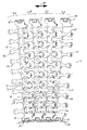
この発明のこれらの特徴及びアスペクツならびにその利点は、以下の記述、添付の請求の範囲及び添付の図面を参照することで、よりよく理解される。この発明の特徴を構成するモジュラーコンベヤベルトを搬走路の曲がる部分においての状態で図1に示す。ベルト10は、互いに並んだ状態での一つ又は複数のベルトモジュール(この例では、一列ごとに二つのモジュールがある:即ち、短い横向きモジュール14と長い横向きモジュール15)の複数の列12A〜12Dから構成されている。各横向きモジュールは、外側側面16,16’から内側側面17,17’にわたっている。外側面は、前記ベルトの第1と第2の側縁18,19を形成している。ヒンジアイ20,20’が各列の第1と第2の端部22,23にそって横方向に離れて位置している。連続の列の間に介在するヒンジアイにおける整合した空隙24,24’でヒンジピン26を受け、これで前記列をつなげて駆動及び遊動スプロケット又はドラムまわりを関節運動できる無端ベルトにするようになっている。前記ベルトを折り返す内側で折り曲がるようにするため、第1の端部22にそうヒンジアイにおける複数の空隙24が溝状になっている。第2の端部23における複数の空隙24’は、断面が円形になっている。当然のことであるが、搬走路に曲がり部分を必要としないベルトには、長くしたヒンジロッド空隙は、無用なものである。
[Detailed description]
These features and aspects of the present invention and the advantages thereof will be better understood with reference to the following description, appended claims and accompanying drawings. A modular conveyor belt constituting the feature of the present invention is shown in FIG. 1 in a state where the conveyor belt is bent. The
側面に端面があるモジュール14,15の間に複数の中間のモジュールを追加してモジュラーベルトの幅寸法を所望の寸法にすることができる。中間の複数のモジュールは、同じような構造のものが一般的であるが、横向きモジュールの端部構造部16,16’を有してはいない。これらのモジュールは、強度の面から煉瓦積みの形状で配置されることが通例である。好ましくは、前記モジュール類は、ポリエチレン、ポリプロピレン又はアセタールのような熱可塑性ポリマーを用い射出成形工程で形成される。この種のモジュラーベルト類は、例えば、米国ルイジアナ、ハラハン在のIntralox,L.L.C.から入手できる。
A plurality of intermediate modules can be added between the
図1に示すように、ベルト10は、搬走路にそって曲がるようになっている。曲がり部分の内側における走行部分は、当該曲がり部分の外側の走行部分よりも短くなっているから、曲がるように構成されているコンベヤベルトは、前記ベルト幅における内外走行長さの差が調節できるようになっていなければならない。複数のヒンジアイの第2のセットにおける長くなっているヒンジロッド空隙により前記ベルト10が曲がり部分の内側で折れ曲がるようになっている。曲がるとき、前記ベルトもまたコンベヤフレームに設けられたサイドレール30に向けて引かれる。前記ベルトの側面とサイドレールとが擦れるように接触して、大きな摩擦作用が生じる。パッド形状のベアリング部材32が端部側に配置のモジュールの外側面16,16’に枢着されていて、前記ベルトの側面を摩擦作用、即ち、前記端部側に位置するモジュールの連続する加熱による摩耗又は品質劣化により加速される減りを防ぐようになっている。前記複数のパッド類は、耐久性がある素材、例えば、カーボンスチール、ステンレススチール又はナイロンなどのようなもので作れていることが好ましい。
As shown in FIG. 1, the
図2A.図2Bには、一つの列における端部側の横向きモジュールの一つの形態の外側部が図示されている。端部側のモジュール34の構造は、図1のものと若干異なるが、機能は同じようなものである。図2Aによく示されているように、前記モジュール本体の外側部分における凹部40に、前記モジュールの長さ方向にそって長軸38をもつシリンドリカルなバレルの形状をしたアクスル36が設けられている。パッド32(図2B)がこのアクスルにクリップされ、該パッドは、ある範囲にわたり回動できるようになっている。図3A,図3Bに示すように、前記パッドには、外側ベアリング面42と、これに対向する内側面44とが含まれている。2本のアーム46,47が前記内側面からフック部分の端部48,49までのびていて、咽喉部45を囲む開口肩部を形成している。前記アームを支持する支柱50,51が付加されている。前記肩部の内側の曲面部52,53と前記パッドの内面の曲面部54は、前記端部側モジュールのアクスル36を受け、回動できるようになって入る。前記パッドは、前記肩部の咽喉部を介して前記アクスルに係合される。前記フック部により前記パッドは、前記アクスルに保持される。前記パッドの曲面部が前記アクスルの外面部まわりにまたがるようになり、前記端部側のモジュールの面に対する前記パッドの向きが変わるようになっている。
FIG. 2A. FIG. 2B illustrates the outer part of one form of end-facing sideways module in one row. The structure of the
前記モジュール34に対する前記パッド32の回動範囲を図4に示すもので、この図においては、前記モジュールの面をその横方向の中心線56、即ち、前記端部モジュールの上部58と底部59との間の中間で概ね示す。前記パッドは、アクスル36を回動中心として第1の位置32’まで上方へ回動し、第2の位置32”まで下方へ回動するようにうなっている。この回動の角度範囲αは、この例では前記中心線に対し対称になっているが、非対称であってもよい。図5Aに示すように、ベルトの端部を摩耗する帯片58で支承している。前記パッド32の外側ベアリング面42は、前記コンベヤのサイドレール30に接している。図5Aに示すような理想的な搬送状態にあっては、前記ベアリング面は、前記端部側モジュールの面に対しほぼ垂直になっている。しかしながら、場合によっては、ベルトがカーブ部分を走行するとき、前記ベルトの外側が図5Bに示すように前記コンベヤフレームから浮き上がるようなことがある。このような状態における前記ベルトの面は、前記レールの面に対し垂直ではなくなってしまう。しかしながら、前記パッドは、前記アクスルを中心としてスイベル運動できるので、前記ベアリング面42の前記サイドレールとの接触領域は、最大になる。前記ベルトの面が其の理想的な水平方位に対し変化すると、前記スイベルパッドは、常に前記レールに対し最大に接触できる位置をとるようになる。このようにして、前記パッドは、自己調節を行う。
FIG. 4 shows the rotation range of the
スイベルパッドの別の例を図6に示す。この例では、端部側モジュール60は、外側に凹部62を有している。前記凹部を囲む対向壁64,65は、これらに形成された受け部66を有している。外側ベアリング面70をもつパッド68は、脚部72を有し、この脚部は、短い突出部74,75をもつ内側部からのびているもので、前記突出部は、前記受け部で受けられている。このようにして、前記パッドは、長さ方向に位置が合っている受け部で構成される長さ方向軸76まわりを回転できるようになっている。
Another example of the swivel pad is shown in FIG. In this example, the end module 60 has a recess 62 on the outside. The opposing walls 64 and 65 surrounding the recess have a receiving
このように、この発明は、いくつかの好ましい例について詳細に記載したものである。しかしながら、別の例も可能である。例えば、前記パッドと端部側モジュールとの間の結合をボールとソケットで行い、前記パッドが記載した例の1本の軸のかわりに多数の軸まわりをスイベル運動できるようにする。別の例としては、前記パッドを各列に取り付けたり、前記ベルトの両側に取り付けたりすることを必要としない場合もある。このように、これらの例は、例示であって、この発明の範囲を詳細に記載の例の詳細に限定されるべきものではいことを意味している。 Thus, the present invention has been described in detail with reference to a few preferred examples. However, other examples are possible. For example, the pad and the end module are coupled with a ball and socket so that the pad can swivel around multiple axes instead of the single axis of the example described. As another example, it may not be necessary to attach the pads to each row or to be attached to both sides of the belt. Thus, these examples are illustrative and mean that the scope of the invention should not be limited to the details of the examples described in detail.
10 ベルト
14 短い横向きモジュール
15 長い横向きモジュール
20,20’ ヒンジアイ
24、24’ 空隙
26 ヒンジピン
30 サイドレール
32 パッド形状のベアリング部材
DESCRIPTION OF
Claims (9)
複数の列のベルトがヒンジを介して端部同士で相互接続して一連のコンベヤベルトを形成し、
前記各列のベルトは、第1の側縁から第2の側縁にわたってベルト走行方向と交差する横方向にのびており、前記第1の側縁にはパッド形状のベアリング部材がピボット回動可能に連結され、
前記ベアリング部材は、外面にパッド面をもち、そのパッド面の向きが前記ピボット回動により前記第1の側縁に対して変えられるもの。 Modular conveyor belt with the following configuration:
Multiple rows of belts interconnected at the ends via hinges to form a series of conveyor belts,
Wherein each row of the belt, from the first side edge and extends in the transverse direction intersecting the second side edge belt running direction Niwata, the first of the side edges of the pad-shaped bearing member pivots times Movably linked,
The bearing member has a pad surface on the outer surface, and the direction of the pad surface is changed with respect to the first side edge by the pivot rotation .
前記第2のベアリング部材は、外面にパッド面をもち、そのパッド面の向きがピボット回動により前記第2の側縁に対して変えられる請求項1におけるモジュラーコンベヤベルト。 A pad-shaped second bearing member is pivotably connected to the second side edge ,
The modular conveyor belt according to claim 1, wherein the second bearing member has a pad surface on an outer surface, and the orientation of the pad surface is changed with respect to the second side edge by pivoting .
この端部側モジュールは、前記第1の側縁にベルト走行方向に沿う軸を備え、
前記ベアリング部材は、前記パッド面を形成しているパッドと、前記軸に対向する内面でピボット回動可能に保持された2本のアームと、を備えている請求項1におけるモジュラーコンベヤベルト。 Each row of belts includes an end module on a first side of the belt;
The end side module includes an axis along the belt traveling direction at the first side edge ,
The bearing member includes a pad forming the pad surface, a modular conveyor belt as in claim 1, and a, and two arms held pivotably rotated by the inner surfaces facing the shaft.
この端部側モジュールは、対向壁によって前記ベアリング部材の受け部を形成するように前記第1の側縁に向けて開放されている凹部を備え、
前記ベアリング部材は、前記パッド面を形成しているパッドと、前記パッドの裏面から突出して前記受け部と係合して前記凹部で前記パッドをピボット回動可能に保持させるための軸状の短い突出部を備えた脚部と、を含む請求項1におけるモジュラーコンベヤベルト。 Each row of belts includes an end module on a first side of the belt;
This end-side module is provided with a recess which is open toward the first side edge to form a receiving portion of the opposing walls Accordingly the bearing member,
The bearing member has a pad that forms the pad surface , a short shaft that protrudes from the back surface of the pad and engages with the receiving portion to hold the pad in a pivotable manner in the recess. The modular conveyor belt according to claim 1, comprising leg portions with protrusions.
第1の端部から第2の端部にわたってベルト走行方向に沿う長さ方向にのび、第1の側縁から第2の側縁にわたってベルト走行方向と交差する横方向にのび、上面から底面にかけて厚みをもつモジュラー本体;
前記第1の端部と前記第2の端部とから長さ方向に沿って突出すると共に前記第1の側縁から前記第2の側縁にわたって横方向に離れて形成された複数のヒンジアイ;及び
前記第1の側縁にピボット回動可能に取り付けられて外面のパッド面の向きが前記ピボット回動により前記第1の側縁に対して変えられるパッド形状のベアリング部材。 End module for modular conveyor belts with the following configuration:
Extending in the longitudinal direction along the direction of belt travel over from the first end to the second end extends laterally from the first side edge over the second side edge intersecting the direction of belt travel, Modular body with thickness from top to bottom;
Said first end and said second end said with projecting along the longitudinal direction from the first from the side edge a plurality of which are formed apart laterally across the second side edge hinge eyes; as well as
A pad-shaped bearing member attached to the first side edge so as to be pivotable so that an orientation of an outer pad surface can be changed with respect to the first side edge by the pivoting .
この軸に前記ベアリング部材がピボット回転可能に取り付けられている請求項7における端部モジュール。 A shaft along the belt running direction is provided on the first side edge of the module body,
8. The end module according to claim 7 , wherein the bearing member is pivotally attached to the shaft .
前記ベアリング部材は、前記パッド面を形成しているパッドと、前記対向壁によって前記ベアリング部材の受け部を形成するように前記第1の側縁に向けて開放されている凹部を備え、
前記ベアリング部材は、前記パッド面を形成しているパッドと、前記パッドの裏面から突出して前記受け部と係合して前記凹部で前記パッドをピボット回動可能に保持させるための軸状の短い突出部を備えた脚部と、含む請求項7における端部モジュール。 It said first side edge is provided with a recess which is open toward the first side edge to form a receiving portion of the opposing walls Accordingly the bearing member,
The bearing member includes a pad forming the pad surface, the opposing walls Accordingly recess is open toward a side edge of the first so as to form a receiving portion of said bearing member,
The bearing member has a pad that forms the pad surface , a short shaft that protrudes from the back surface of the pad and engages with the receiving portion to hold the pad in a pivotable manner in the recess. The end module according to claim 7 , comprising a leg with a protrusion.
Applications Claiming Priority (2)
| Application Number | Priority Date | Filing Date | Title |
|---|---|---|---|
| US52180704P | 2004-07-06 | 2004-07-06 | |
| US60/521,807 | 2004-07-06 |
Publications (2)
| Publication Number | Publication Date |
|---|---|
| JP2006021932A JP2006021932A (en) | 2006-01-26 |
| JP4963541B2 true JP4963541B2 (en) | 2012-06-27 |
Family
ID=34941807
Family Applications (1)
| Application Number | Title | Priority Date | Filing Date |
|---|---|---|---|
| JP2005197064A Active JP4963541B2 (en) | 2004-07-06 | 2005-07-06 | Module with conveyor belt and self-adjusting end |
Country Status (10)
| Country | Link |
|---|---|
| US (1) | US7234589B2 (en) |
| EP (1) | EP1614644B1 (en) |
| JP (1) | JP4963541B2 (en) |
| CN (1) | CN1721299B (en) |
| AT (1) | ATE355241T1 (en) |
| BR (1) | BRPI0502603A (en) |
| CA (1) | CA2511459A1 (en) |
| DE (1) | DE602005000619T2 (en) |
| DK (1) | DK1614644T3 (en) |
| MX (1) | MXPA05007347A (en) |
Families Citing this family (24)
| Publication number | Priority date | Publication date | Assignee | Title |
|---|---|---|---|---|
| US6330941B1 (en) * | 2000-05-25 | 2001-12-18 | Habasit Ag | Radius conveyor belt |
| US7971707B2 (en) * | 2009-05-07 | 2011-07-05 | Habasit Ag | Snap-in wear guide |
| IT1396487B1 (en) | 2009-12-04 | 2012-12-14 | Bett Sistemi Srl | CONVOGLIATORE. |
| DK201000294A (en) * | 2010-04-08 | 2011-10-09 | Ammeraal Beltech Modular As | Restrictor clip |
| US8574044B2 (en) | 2010-08-11 | 2013-11-05 | Industrial Design Fabrication & Installation, Inc. | Belly hook assembly for a conveyor |
| US8074791B1 (en) | 2010-08-11 | 2011-12-13 | Industrial Design Fabrication & Installation, Inc. | Hook assembly for a conveyor belt |
| KR20140007072A (en) * | 2011-01-27 | 2014-01-16 | 라이트람, 엘엘씨 | Conveyor belt and module with magnets |
| EP2546175B1 (en) * | 2011-07-13 | 2016-12-14 | Forbo Siegling Gmbh | Transport device |
| WO2013029624A1 (en) | 2011-08-29 | 2013-03-07 | Ammeraal Beltech Modular A/S | Width extension part for modular belt |
| BR112014013875B1 (en) * | 2011-12-06 | 2021-05-18 | Ashworth Bros., Inc. | connection for a conveyor belt, conveyor belt, conveyor belt including a connection and method of mounting a conveyor belt |
| NL2009542C2 (en) | 2012-03-07 | 2013-09-10 | Rexnord Flattop Europe Bv | MODULAR TRANSPORT SYSTEM. |
| IN2014DN06476A (en) | 2012-03-28 | 2015-06-12 | Schaeffler Technologies Ag | |
| WO2013181354A1 (en) * | 2012-05-30 | 2013-12-05 | Rexnord Industries, Llc | Conveyor belt module with bearing retainer |
| US8899409B2 (en) * | 2012-06-13 | 2014-12-02 | Ashworth Bros., Inc. | Conveyor belt link having wear resistant portion |
| US8857608B2 (en) | 2012-07-31 | 2014-10-14 | Ashworth Bros., Inc | Link member having replaceable wear component |
| ITPD20120267A1 (en) * | 2012-09-14 | 2014-03-15 | Alit S R L | PERFECTED JERSEY FOR SIDE CHAIN FOR CONVEYOR BELTS |
| CA2888898A1 (en) | 2012-10-25 | 2014-05-01 | Solus Industrial Innovations, Llc | Device and method for controlling the wear of the rail of a conveyor |
| MX2015006770A (en) | 2012-11-29 | 2015-10-29 | Solus Ind Innovations Llc | Side-flexing conveyors. |
| US9663298B2 (en) * | 2014-12-18 | 2017-05-30 | Laitram, L.L.C. | Conveyor belt module with shaped bottom surface |
| US10647512B2 (en) * | 2016-04-07 | 2020-05-12 | Laitram, L.L.C. | Drive and sideguard belt insert for a modular plastic conveyor belt |
| US10947048B2 (en) * | 2017-07-12 | 2021-03-16 | Habasit Ag | Positive drive for a spiral conveyor and belt module for a radius or spiral conveyor |
| CN107720093B (en) * | 2017-09-30 | 2019-05-17 | 浙江瀚镪自动化设备股份有限公司 | Separate type conveyer belt |
| US20220281689A1 (en) * | 2019-05-03 | 2022-09-08 | Ammeraal Beltech Modular A/S | Modular conveyor belt link |
| EP4010275A4 (en) | 2019-08-07 | 2023-08-30 | Laitram, L.L.C. | Roller belt with support edges |
Family Cites Families (15)
| Publication number | Priority date | Publication date | Assignee | Title |
|---|---|---|---|---|
| ZA786373B (en) | 1977-11-22 | 1979-10-31 | Umec Boydell Ltd | Improvements relating to belt conveyors |
| GB2008523A (en) * | 1977-11-22 | 1979-06-06 | Umec Boydell Belt Ing Ltd | Improvements relating to belt conveyors |
| US5181601A (en) * | 1990-10-09 | 1993-01-26 | Palmaer K V | Plastic conveyor belt with integral sideplate |
| US5280833A (en) * | 1991-08-27 | 1994-01-25 | Andre Robin | Turn conveyor with reduced friction feature |
| DK132993A (en) * | 1993-01-21 | 1994-07-22 | Baeltix Maskinfabrikken As | Chain link conveyor |
| US5372248A (en) * | 1994-01-18 | 1994-12-13 | The Laitram Corporation | Radius conveyor belt |
| US5738205A (en) * | 1994-04-15 | 1998-04-14 | Drobel; Jorgen | Conveyor chain having a supporting face consitituted by chain links transversal to the longitudinal direction of the chain |
| US5779027A (en) | 1996-02-14 | 1998-07-14 | Rexnord Corporation | Sideflexing conveyor including lubrication inserts |
| US5775480A (en) * | 1996-06-14 | 1998-07-07 | The Laitram Corporation | Low-friction conveyor assembly |
| US5782340A (en) * | 1997-03-06 | 1998-07-21 | Dolan; Rex H. | Tapered side support for conveyor belts |
| US6073756A (en) * | 1998-01-23 | 2000-06-13 | Uni-Chains A/S | Side-flexing conveyor belt |
| NL1008189C2 (en) * | 1998-02-03 | 1999-08-04 | Kaak Johan H B | Link belt with links provided with a number of link parts for transporting products. |
| US6471046B2 (en) * | 1998-02-18 | 2002-10-29 | Span Tech Llc | Reduced drag side flexing conveyor system |
| US6640957B2 (en) * | 2001-12-21 | 2003-11-04 | Otis Elevator Company | Racetrack style passenger conveyor |
| US6578704B1 (en) * | 2002-11-18 | 2003-06-17 | The Laitran Corporation | Belts and belt modules for spiral conveyors |
-
2005
- 2005-07-04 EP EP05254183A patent/EP1614644B1/en not_active Not-in-force
- 2005-07-04 AT AT05254183T patent/ATE355241T1/en not_active IP Right Cessation
- 2005-07-04 DE DE602005000619T patent/DE602005000619T2/en active Active
- 2005-07-04 DK DK05254183T patent/DK1614644T3/en active
- 2005-07-05 CA CA002511459A patent/CA2511459A1/en not_active Abandoned
- 2005-07-06 MX MXPA05007347A patent/MXPA05007347A/en active IP Right Grant
- 2005-07-06 CN CN2005100818891A patent/CN1721299B/en not_active Expired - Fee Related
- 2005-07-06 BR BRPI0502603-2A patent/BRPI0502603A/en not_active IP Right Cessation
- 2005-07-06 US US11/160,709 patent/US7234589B2/en active Active
- 2005-07-06 JP JP2005197064A patent/JP4963541B2/en active Active
Also Published As
| Publication number | Publication date |
|---|---|
| JP2006021932A (en) | 2006-01-26 |
| BRPI0502603A (en) | 2006-02-21 |
| US7234589B2 (en) | 2007-06-26 |
| US20060006050A1 (en) | 2006-01-12 |
| ATE355241T1 (en) | 2006-03-15 |
| DE602005000619T2 (en) | 2007-06-21 |
| EP1614644B1 (en) | 2007-02-28 |
| EP1614644A1 (en) | 2006-01-11 |
| DE602005000619D1 (en) | 2007-04-12 |
| MXPA05007347A (en) | 2006-05-25 |
| CN1721299A (en) | 2006-01-18 |
| DK1614644T3 (en) | 2007-06-04 |
| CA2511459A1 (en) | 2006-01-06 |
| CN1721299B (en) | 2010-07-28 |
Similar Documents
| Publication | Publication Date | Title |
|---|---|---|
| JP4963541B2 (en) | Module with conveyor belt and self-adjusting end | |
| US8579104B2 (en) | Conveyor belt and module accommodating rod growth | |
| US7255227B2 (en) | Hinge rod retention in modular conveyor belt edges by means of resilient blocking elements | |
| JP4199113B2 (en) | Modular conveyor belt with non-circular hinge pins | |
| KR101659605B1 (en) | Sorting feeder | |
| US20050067262A1 (en) | Rodless conveyor belt or chain | |
| KR20120103680A (en) | Conveyor transfer system with floating transfer platform | |
| US7131531B1 (en) | Roller shoes in modular-belt conveyors | |
| US20070102261A1 (en) | Transfer system | |
| US20100231034A1 (en) | Tracked vehicle | |
| US6279729B1 (en) | Article conveyance having mechanical drive | |
| US5992615A (en) | Curved conveyor section | |
| US8689969B2 (en) | Conveyors and transmission belts | |
| US20060054471A1 (en) | Three-dimensional carrying conveyor | |
| US3317030A (en) | Articulated-section conveyor structure | |
| US20040173441A1 (en) | Roller top conveyor chain assembly | |
| CN217171967U (en) | Belt turning device and belt conveyor | |
| CN110803476B (en) | Flexible conveying device for logistics sorting equipment | |
| JPH0371325B2 (en) | ||
| US20020175056A1 (en) | Side-flexing conveyor belt | |
| JP2008536773A (en) | Anti-friction roller support for modular link conveyor chains | |
| US10633187B2 (en) | Radius and variable width conveyor belt | |
| JP4274404B2 (en) | Chain conveyor | |
| MXPA02007280A (en) | Padded chain for a conveyor. | |
| RU2317930C1 (en) | Conveyer with overhead belt |
Legal Events
| Date | Code | Title | Description |
|---|---|---|---|
| A621 | Written request for application examination |
Free format text: JAPANESE INTERMEDIATE CODE: A621 Effective date: 20080616 |
|
| A131 | Notification of reasons for refusal |
Free format text: JAPANESE INTERMEDIATE CODE: A131 Effective date: 20110628 |
|
| A977 | Report on retrieval |
Free format text: JAPANESE INTERMEDIATE CODE: A971007 Effective date: 20110630 |
|
| A521 | Request for written amendment filed |
Free format text: JAPANESE INTERMEDIATE CODE: A523 Effective date: 20110921 |
|
| TRDD | Decision of grant or rejection written | ||
| A01 | Written decision to grant a patent or to grant a registration (utility model) |
Free format text: JAPANESE INTERMEDIATE CODE: A01 Effective date: 20120321 |
|
| A01 | Written decision to grant a patent or to grant a registration (utility model) |
Free format text: JAPANESE INTERMEDIATE CODE: A01 |
|
| A61 | First payment of annual fees (during grant procedure) |
Free format text: JAPANESE INTERMEDIATE CODE: A61 Effective date: 20120326 |
|
| R150 | Certificate of patent or registration of utility model |
Free format text: JAPANESE INTERMEDIATE CODE: R150 Ref document number: 4963541 Country of ref document: JP Free format text: JAPANESE INTERMEDIATE CODE: R150 |
|
| FPAY | Renewal fee payment (event date is renewal date of database) |
Free format text: PAYMENT UNTIL: 20150406 Year of fee payment: 3 |
|
| R250 | Receipt of annual fees |
Free format text: JAPANESE INTERMEDIATE CODE: R250 |
|
| R250 | Receipt of annual fees |
Free format text: JAPANESE INTERMEDIATE CODE: R250 |
|
| R250 | Receipt of annual fees |
Free format text: JAPANESE INTERMEDIATE CODE: R250 |
|
| R250 | Receipt of annual fees |
Free format text: JAPANESE INTERMEDIATE CODE: R250 |
|
| R250 | Receipt of annual fees |
Free format text: JAPANESE INTERMEDIATE CODE: R250 |
|
| R250 | Receipt of annual fees |
Free format text: JAPANESE INTERMEDIATE CODE: R250 |
|
| R250 | Receipt of annual fees |
Free format text: JAPANESE INTERMEDIATE CODE: R250 |
|
| R250 | Receipt of annual fees |
Free format text: JAPANESE INTERMEDIATE CODE: R250 |
|
| R250 | Receipt of annual fees |
Free format text: JAPANESE INTERMEDIATE CODE: R250 |