JP4962103B2 - Rolling bearings for dental handpieces - Google Patents
Rolling bearings for dental handpieces Download PDFInfo
- Publication number
- JP4962103B2 JP4962103B2 JP2007100848A JP2007100848A JP4962103B2 JP 4962103 B2 JP4962103 B2 JP 4962103B2 JP 2007100848 A JP2007100848 A JP 2007100848A JP 2007100848 A JP2007100848 A JP 2007100848A JP 4962103 B2 JP4962103 B2 JP 4962103B2
- Authority
- JP
- Japan
- Prior art keywords
- cage
- inner ring
- outer ring
- curvature
- ring raceway
- Prior art date
- Legal status (The legal status is an assumption and is not a legal conclusion. Google has not performed a legal analysis and makes no representation as to the accuracy of the status listed.)
- Active
Links
Images


Classifications
-
- A—HUMAN NECESSITIES
- A61—MEDICAL OR VETERINARY SCIENCE; HYGIENE
- A61C—DENTISTRY; APPARATUS OR METHODS FOR ORAL OR DENTAL HYGIENE
- A61C1/00—Dental machines for boring or cutting ; General features of dental machines or apparatus, e.g. hand-piece design
- A61C1/08—Machine parts specially adapted for dentistry
- A61C1/18—Flexible shafts; Clutches or the like; Bearings or lubricating arrangements; Drives or transmissions
- A61C1/181—Bearings or lubricating arrangements, e.g. air-cushion bearings
-
- F—MECHANICAL ENGINEERING; LIGHTING; HEATING; WEAPONS; BLASTING
- F16—ENGINEERING ELEMENTS AND UNITS; GENERAL MEASURES FOR PRODUCING AND MAINTAINING EFFECTIVE FUNCTIONING OF MACHINES OR INSTALLATIONS; THERMAL INSULATION IN GENERAL
- F16C—SHAFTS; FLEXIBLE SHAFTS; ELEMENTS OR CRANKSHAFT MECHANISMS; ROTARY BODIES OTHER THAN GEARING ELEMENTS; BEARINGS
- F16C33/00—Parts of bearings; Special methods for making bearings or parts thereof
- F16C33/30—Parts of ball or roller bearings
- F16C33/38—Ball cages
- F16C33/41—Ball cages comb-shaped
-
- F—MECHANICAL ENGINEERING; LIGHTING; HEATING; WEAPONS; BLASTING
- F16—ENGINEERING ELEMENTS AND UNITS; GENERAL MEASURES FOR PRODUCING AND MAINTAINING EFFECTIVE FUNCTIONING OF MACHINES OR INSTALLATIONS; THERMAL INSULATION IN GENERAL
- F16C—SHAFTS; FLEXIBLE SHAFTS; ELEMENTS OR CRANKSHAFT MECHANISMS; ROTARY BODIES OTHER THAN GEARING ELEMENTS; BEARINGS
- F16C33/00—Parts of bearings; Special methods for making bearings or parts thereof
- F16C33/30—Parts of ball or roller bearings
- F16C33/38—Ball cages
- F16C33/44—Selection of substances
-
- F—MECHANICAL ENGINEERING; LIGHTING; HEATING; WEAPONS; BLASTING
- F16—ENGINEERING ELEMENTS AND UNITS; GENERAL MEASURES FOR PRODUCING AND MAINTAINING EFFECTIVE FUNCTIONING OF MACHINES OR INSTALLATIONS; THERMAL INSULATION IN GENERAL
- F16C—SHAFTS; FLEXIBLE SHAFTS; ELEMENTS OR CRANKSHAFT MECHANISMS; ROTARY BODIES OTHER THAN GEARING ELEMENTS; BEARINGS
- F16C33/00—Parts of bearings; Special methods for making bearings or parts thereof
- F16C33/30—Parts of ball or roller bearings
- F16C33/58—Raceways; Race rings
- F16C33/583—Details of specific parts of races
- F16C33/586—Details of specific parts of races outside the space between the races, e.g. end faces or bore of inner ring
-
- F—MECHANICAL ENGINEERING; LIGHTING; HEATING; WEAPONS; BLASTING
- F16—ENGINEERING ELEMENTS AND UNITS; GENERAL MEASURES FOR PRODUCING AND MAINTAINING EFFECTIVE FUNCTIONING OF MACHINES OR INSTALLATIONS; THERMAL INSULATION IN GENERAL
- F16C—SHAFTS; FLEXIBLE SHAFTS; ELEMENTS OR CRANKSHAFT MECHANISMS; ROTARY BODIES OTHER THAN GEARING ELEMENTS; BEARINGS
- F16C19/00—Bearings with rolling contact, for exclusively rotary movement
- F16C19/54—Systems consisting of a plurality of bearings with rolling friction
- F16C19/546—Systems with spaced apart rolling bearings including at least one angular contact bearing
- F16C19/547—Systems with spaced apart rolling bearings including at least one angular contact bearing with two angular contact rolling bearings
-
- F—MECHANICAL ENGINEERING; LIGHTING; HEATING; WEAPONS; BLASTING
- F16—ENGINEERING ELEMENTS AND UNITS; GENERAL MEASURES FOR PRODUCING AND MAINTAINING EFFECTIVE FUNCTIONING OF MACHINES OR INSTALLATIONS; THERMAL INSULATION IN GENERAL
- F16C—SHAFTS; FLEXIBLE SHAFTS; ELEMENTS OR CRANKSHAFT MECHANISMS; ROTARY BODIES OTHER THAN GEARING ELEMENTS; BEARINGS
- F16C2208/00—Plastics; Synthetic resins, e.g. rubbers
- F16C2208/20—Thermoplastic resins
- F16C2208/36—Polyarylene ether ketones [PAEK], e.g. PEK, PEEK
-
- F—MECHANICAL ENGINEERING; LIGHTING; HEATING; WEAPONS; BLASTING
- F16—ENGINEERING ELEMENTS AND UNITS; GENERAL MEASURES FOR PRODUCING AND MAINTAINING EFFECTIVE FUNCTIONING OF MACHINES OR INSTALLATIONS; THERMAL INSULATION IN GENERAL
- F16C—SHAFTS; FLEXIBLE SHAFTS; ELEMENTS OR CRANKSHAFT MECHANISMS; ROTARY BODIES OTHER THAN GEARING ELEMENTS; BEARINGS
- F16C2208/00—Plastics; Synthetic resins, e.g. rubbers
- F16C2208/20—Thermoplastic resins
- F16C2208/52—Polyphenylene sulphide [PPS]
-
- F—MECHANICAL ENGINEERING; LIGHTING; HEATING; WEAPONS; BLASTING
- F16—ENGINEERING ELEMENTS AND UNITS; GENERAL MEASURES FOR PRODUCING AND MAINTAINING EFFECTIVE FUNCTIONING OF MACHINES OR INSTALLATIONS; THERMAL INSULATION IN GENERAL
- F16C—SHAFTS; FLEXIBLE SHAFTS; ELEMENTS OR CRANKSHAFT MECHANISMS; ROTARY BODIES OTHER THAN GEARING ELEMENTS; BEARINGS
- F16C2240/00—Specified values or numerical ranges of parameters; Relations between them
- F16C2240/40—Linear dimensions, e.g. length, radius, thickness, gap
- F16C2240/70—Diameters; Radii
- F16C2240/76—Osculation, i.e. relation between radii of balls and raceway groove
-
- F—MECHANICAL ENGINEERING; LIGHTING; HEATING; WEAPONS; BLASTING
- F16—ENGINEERING ELEMENTS AND UNITS; GENERAL MEASURES FOR PRODUCING AND MAINTAINING EFFECTIVE FUNCTIONING OF MACHINES OR INSTALLATIONS; THERMAL INSULATION IN GENERAL
- F16C—SHAFTS; FLEXIBLE SHAFTS; ELEMENTS OR CRANKSHAFT MECHANISMS; ROTARY BODIES OTHER THAN GEARING ELEMENTS; BEARINGS
- F16C2300/00—Application independent of particular apparatuses
- F16C2300/10—Application independent of particular apparatuses related to size
- F16C2300/12—Small applications, e.g. miniature bearings
-
- F—MECHANICAL ENGINEERING; LIGHTING; HEATING; WEAPONS; BLASTING
- F16—ENGINEERING ELEMENTS AND UNITS; GENERAL MEASURES FOR PRODUCING AND MAINTAINING EFFECTIVE FUNCTIONING OF MACHINES OR INSTALLATIONS; THERMAL INSULATION IN GENERAL
- F16C—SHAFTS; FLEXIBLE SHAFTS; ELEMENTS OR CRANKSHAFT MECHANISMS; ROTARY BODIES OTHER THAN GEARING ELEMENTS; BEARINGS
- F16C2316/00—Apparatus in health or amusement
- F16C2316/10—Apparatus in health or amusement in medical appliances, e.g. in diagnosis, dentistry, instruments, prostheses, medical imaging appliances
- F16C2316/13—Dental machines
Description
本発明は、例えばストレートハンドピースやアングルハンドピースなどの歯科用ハンドピースに用いられる転がり軸受に関する。 The present invention relates to a rolling bearing used for a dental handpiece such as a straight handpiece or an angle handpiece.
従来から、例えばストレートハンドピースやアングルハンドピースなどの歯科用ハンドピースが知られている(例えば特許文献1及び2参照)。
Conventionally, dental handpieces such as straight handpieces and angle handpieces are known (see, for example,
このような歯科用のアングルハンドピースの一例を図1に示す。図1(a)は歯科用ハンドピースの外観図、(b)は歯科用ハンドピースのヘッド部の拡大断面図、(c)はヘッド部に用いられた転がり軸受の部分横断面図である。 An example of such a dental angle handpiece is shown in FIG. 1A is an external view of a dental handpiece, FIG. 1B is an enlarged cross-sectional view of a head portion of the dental handpiece, and FIG. 1C is a partial cross-sectional view of a rolling bearing used in the head portion.
歯科用ハンドピース1は、ヘッド部3にドリルや砥石など各種の工具5を着脱自在に装着し、工具5を高速回転させる機構になっている。ヘッド部3の構成を具体的に説明すると、工具5はヘッド部3内の回転軸7に装着され、回転軸7はその軸方向上下一対の転がり軸受9,9を介してハウジング11に回転自在に支持されている。さらに、回転軸7には、一対の転がり軸受9,9の間の部分にタービン翼13が取り付けられており、このタービン翼13を空気圧により高速回転させることで、回転軸7、工具5も高速回転させることができる。
The
回転軸7の外周には、工具5に向けて水を噴射する複数の水噴射孔15と、工具に向けて空気を噴射する複数の空気噴射孔17とが配設されている。各水噴射孔15は、回転軸7の周りに設けられた周溝19を介して水導入路21に接続され、各空気噴射孔17は、回転軸7の周りに設けられた周溝23を介して空気導入路25に接続されている。各水噴射孔15及び各空気噴射孔17は互いに対を成し、回転軸7の外周に所定間隔で配設されており、水噴射孔15から噴射された水と空気噴射孔17から噴射された空気とが、工具5に向かう途中で交差するように設計されている。なお、各空気噴射孔17は、各水噴射孔15の内側に配設されている。このような構成により、水噴射孔15から噴射された水が空気噴射孔17から噴射された空気により拡散され、歯科治療中に工具5の全体に効率よく水を噴射することができる。
A plurality of
転がり軸受9,9は、相対回転可能に構成された内輪27及び外輪29と、内外輪間に配列された玉31と、玉31を転動自在に保持する保持器33とを備えている。内輪27は回転軸7に外嵌しており、外輪29はハウジング11に内嵌している。外輪29は一端側にフランジ35を有し、他端側には密封部材37が設けられている。外輪29の胴部には、例えば真鍮製の環状リング39が外嵌されてフランジ35に当接していると共に、例えばゴム製のOリング41が外嵌されて環状リング39に当接している。転がり軸受9,9をヘッド部3に組み込んで位置決めをする際、ハウジング11とOリング41とを当接させることにより、転がり軸受9,9への予圧が付加される。
ところで、歯科用ハンドピース用の転がり軸受は、毎分30万回転以上の高速回転と100℃を越える高温の滅菌処理に耐えること等、非常に高い性能が要求される。より高性能な軸受を実現するためには、軸受の寸法精度や回転精度を上げたり、保持器の材料を工夫したりする必要があった。 By the way, rolling bearings for dental handpieces are required to have very high performance such as being able to withstand high-speed rotation of 300,000 revolutions per minute and high-temperature sterilization treatment exceeding 100 ° C. In order to realize a higher-performance bearing, it was necessary to increase the dimensional accuracy and rotational accuracy of the bearing and to devise materials for the cage.
また、従来ハンドピース用転がり軸受の保持器の材料に樹脂系のものを用いる場合、グラファイトパウダー30%程度、PTFE3%程度のポリアミドイミド(トーロン4275)で形成するものがあったが、この組成では射出成形ができず、削り加工により製作しなければならないため、コストが嵩むという問題があった。 In addition, when a resin-based material is used as a material for a conventional rolling bearing for handpieces, there is one formed of polyamideimide (Toron 4275) of about 30% graphite powder and about 3% PTFE. There is a problem that the cost is increased because the injection molding cannot be performed and it must be manufactured by a shaving process.
そこで、本発明は、コストを抑え、高速回転下での軸受回転性能を向上させた歯科用ハンドピース用の転がり軸受を提供することを目的とする。 Therefore, an object of the present invention is to provide a rolling bearing for a dental handpiece that is low in cost and has improved bearing rotation performance under high-speed rotation.
上記課題を解決するために、本発明は、外周面に内輪軌道を有する内輪と、内周面に外輪軌道を有する外輪と、前記内外輪間において内輪に近接して配置され、前記内輪軌道と前記外輪軌道との間に介在する複数の転動体を、周方向の複数箇所に設けたポケットそれぞれに転動自在に保持する円環状の保持器とを備え、歯科用ハンドピースのヘッド部に内蔵され、前記内輪は工具を取り付ける回転軸に外嵌され、前記外輪はハウジングに内嵌されることで、該回転軸を回転自在に支持する歯科用ハンドピース用の転がり軸受であって、前記保持器は耐熱性を有する樹脂組成物から成り、該樹脂組成物のベース樹脂は、ガラス繊維および/もしくはカーボン繊維を配合したポリフェニレンサルファイド、または、ガラス繊維および/もしくはカーボン繊維を配合したポリエーテルエーテルケトンであり、前記保持器を回転中心軸に垂直な面で切断したときの断面における該前記保持器の内周および外周の真円度を5〜10μmにし、前記回転軸に外嵌される内輪の外周面が前記保持器の案内面となり、該案内面の粗さを0.7s以下にすると共に、該案内面と前記保持器の対向面との隙間を0.02〜0.06mmにしたことを特徴とする。 In order to solve the above problems, the present invention provides an inner ring having an inner ring raceway on an outer peripheral surface, an outer ring having an outer ring raceway on an inner peripheral surface, and an inner ring raceway disposed between the inner and outer rings in proximity to the inner ring, Built in the head part of a dental handpiece with an annular cage that holds a plurality of rolling elements interposed between the outer ring raceway and a plurality of rolling elements in pockets provided in a plurality of circumferential directions. The inner ring is externally fitted to a rotating shaft to which a tool is attached , and the outer ring is fitted to a housing, thereby being a rolling bearing for a dental handpiece that rotatably supports the rotating shaft, the holding The vessel is composed of a heat-resistant resin composition, and the base resin of the resin composition is polyphenylene sulfide containing glass fiber and / or carbon fiber, or glass fiber and / or glass. A polyether ether ketone blended with carbon fibers, and the roundness of the inner periphery and the outer periphery of the said cage in a cross section when cut by a plane perpendicular to the rotation axis of the retainer 5 to 10 [mu] m, the The outer peripheral surface of the inner ring fitted on the rotation shaft becomes the guide surface of the cage, the roughness of the guide surface is 0.7 s or less, and the clearance between the guide surface and the opposing surface of the cage is 0. 0.02 to 0.06 mm.
また、本発明の好ましい態様では、前記複数の転動体は玉であり、前記内輪軌道の溝の曲率を前記玉の曲率に対し55%〜60%にし、前記外輪軌道の溝の曲率を前記玉の曲率に対し60%〜65%にしたことを特徴とする。 In a preferred aspect of the present invention, the plurality of rolling elements are balls, the curvature of the groove of the inner ring raceway is 55% to 60% with respect to the curvature of the ball, and the curvature of the groove of the outer ring raceway is the ball. 60% to 65% with respect to the curvature.
本発明によれば、コストを抑え、高速回転下での軸受回転性能を向上させることができる。 According to the present invention, it is possible to reduce costs and improve bearing rotation performance under high-speed rotation.
以下、本発明の一実施形態について図面を参照して説明する。 Hereinafter, an embodiment of the present invention will be described with reference to the drawings.
図2は、本発明の一実施形態に係る歯科用ハンドピース用の転がり軸受の横断面図である。 FIG. 2 is a cross-sectional view of a rolling bearing for a dental handpiece according to an embodiment of the present invention.
転がり軸受43は、外周面45に内輪軌道47を有する内輪49と、内周面51に外輪軌道53を有する外輪55とを有する。内輪49と外輪55は中心が一致しており、これを符号Oで示す。内輪軌道47と外輪軌道53との間には、複数の転動体57が介在している。本実施形態では転動体57は玉であり、複数の玉は材質、形状とも同一のものであり、同じ符号57で表す。内外輪間には、玉57を、周方向の複数箇所に設けたポケットそれぞれに転動自在に保持する円環状の保持器59が配置されている。保持器59の形状は特に限定されず、冠形保持器、プレス保持器、もみ抜き保持器等のいずれでも良い。保持器59の内周面61は内輪49の外周面45に対向しており、保持器59の外周面63は外輪55の内周面51に対向している。
The rolling
また、外輪55には、軸受内部から潤滑剤が漏洩したり、軸受内部に異物が入り込んだりすることを防ぐため、シールやシールド等の密封部材65が設けられている。転がり軸受43は以上のように構成され、内外輪が回転中心軸X−Xの周りに相対回転自在になっている。
Further, the
転がり軸受43を組み込む歯科用ハンドピースの形態は特に限定されないが、例えば上述した一例(図1参照)と同様のものを考えることができる。ここで、図2に示されるように、本実施形態では外輪55にフランジは形成されていないが、ハンドピースのヘッド部内の構成はほとんど同じにすることができる。また、外輪55をフランジ付外輪にしても良い。外輪55はハウジングに内嵌し、内輪49は、工具を取り付ける回転軸に外嵌する。内輪49が外輪55に対して高速で回転する。
Although the form of the dental handpiece incorporating the rolling
本実施形態においては、内外輪49,55は高耐食ステンレスで形成され、玉57もステンレス又はセラミックで形成される。また、保持器59は外輪55よりも内輪49に近接しており、高速回転時、保持器59は内輪49に案内される。内輪49の、内輪軌道47を除く外周面45部分が、保持器59を案内する案内面となる。なお、別形態として、保持器59が内輪49より外輪55に近接する外輪案内型とすることもできる。この場合には、外輪55の、外輪軌道53を除く内周面51部分が、保持器59の案内面となる。
In the present embodiment, the inner and
保持器59は耐熱性を有する樹脂組成物から成り、該樹脂組成物のベース樹脂は、ガラス繊維および/もしくはカーボン繊維を配合したポリフェニレンサルファイド(PPS)、または、ガラス繊維および/もしくはカーボン繊維を配合したポリエーテルエーテルケトン(PEEK)である。このような材料を用いた保持器59は射出成形が可能であり、保持器製作上の大幅なコストダウンが可能となる。さらに、ハンドピースには高温の滅菌処理が施されるが、上記材料を用いた保持器59は、温度による寸法変化がごくわずかである。また、滅菌処理時にかかる蒸気に対しても、吸水率が非常に少ない材質のため、保持器59の寸法変化はごくわずかである。したがって、上記材料を用いた保持器59によれば、コストダウンと共に、転がり軸受43の回転精度の劣化を防ぐことができる。
The
また、保持器59の内周および外周の真円度、即ち、保持器59を回転中心軸X−Xに垂直な面で切断したときの断面における、保持器59の内周および外周の真円度を、10μm以下にしている。また、保持器59の案内面(上述のように、本実施形態では内輪49の外周面45)の粗さを0.7s以下にしている。さらに、該案内面とこれに対向する保持器59内周面61との隙間を0.02〜0.06mmにしている。このように各値を精密にコントロールすることで、高速回転下での軸受回転精度が確保され、騒音、振動が抑制される。
Further, the roundness of the inner and outer circumferences of the
また、内輪軌道47の溝の曲率を玉57の曲率に対し55%〜60%にし、外輪軌道53の溝の曲率を玉57の曲率に対し60%〜65%にしている。ここで、内外輪軌道47,53の溝の曲率とは、図2の如く、軸受43を回転中心軸X−Xを含む面で切断したときの断面における、各軌道47,53の曲率を意味する。一定圧のエアーで駆動される歯科用ハンドピースは、軸受のトルクにより回転数が左右されるため、軸受のトルクをできるだけ低減することが望ましい。上記のように軌道溝の曲率をコントロールすることで、玉57の転動面と内輪軌道47及び外輪軌道53との当接部分に形成される接触楕円が小さくなる。そのため、回転時にこの接触楕円部分で生じる転がり抵抗、スピンが小さくなり、軸受43のトルクが低減され、一定のエアー圧でさらなる回転数アップが可能となる。
Further, the curvature of the groove of the
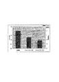
図3乃至6に、本実施形態の歯科用ハンドピース用の転がり軸受と形状および材質が等しい転がり軸受を用いて、上述の保持器真円度(μm)、案内面粗さ(s)、案内隙間(mm)、内外輪軌道の溝の曲率の各値と、回転数との関係を示す。回転数は毎分40万回転を1として回転数比で示した。また、併せて、図3では振動比、図6ではトルク比についての試験結果も示した。なお、試験に用いた軸受はSR144であり、予圧は0.3kgfとした。 3 to 6, using the rolling bearing having the same shape and material as the rolling bearing for the dental handpiece of the present embodiment, the above-described cage roundness (μm), guide surface roughness (s), and guidance are provided. The relationship between the clearance (mm), each value of the curvature of the groove of the inner and outer ring raceways, and the rotational speed is shown. The number of rotations is shown as a rotation number ratio with 1 being 400,000 rotations per minute. In addition, FIG. 3 also shows the test results for the vibration ratio and FIG. 6 for the torque ratio. The bearing used for the test was SR144, and the preload was 0.3 kgf.
図3は、保持器真円度と、振動および回転数との関係を示すグラフである。保持器真円度が10μmを越えたあたりから振動が増加し、回転数は徐々に減少していることがわかる。本実施形態によれば、保持器真円度を10μm以下にしているので、振動を抑え、大きな回転数を確保することができる。 FIG. 3 is a graph showing the relationship between the roundness of the cage, the vibration and the rotational speed. It can be seen that the vibration increases when the roundness of the cage exceeds 10 μm, and the rotational speed gradually decreases. According to the present embodiment, since the roundness of the cage is 10 μm or less, vibration can be suppressed and a large rotation speed can be ensured.
図4は、案内面粗さと回転数との関係を示すグラフである。案内面粗さが1sを越えたあたりから、回転数比が減少して1より小さくなっていることがわかる。本実施形態によれば、案内面粗さを0.7s以下にしているので、大きな回転数を確保することができる。 FIG. 4 is a graph showing the relationship between the guide surface roughness and the rotational speed. It can be seen that the rotational speed ratio decreases and becomes smaller than 1 when the guide surface roughness exceeds 1 s. According to this embodiment, since the guide surface roughness is 0.7 s or less, a large rotational speed can be ensured.
図5は、案内隙間と回転数との関係を示すグラフである。案内隙間が小さ過ぎても大き過ぎても、回転数比は1に達しないことがわかる。本実施形態によれば、案内隙間を0.02〜0.06mmの範囲内に調整しているので、大きな回転数を確保することができる。 FIG. 5 is a graph showing the relationship between the guide gap and the rotation speed. It can be seen that the rotation speed ratio does not reach 1 when the guide gap is too small or too large. According to this embodiment, since the guide gap is adjusted within the range of 0.02 to 0.06 mm, a large rotational speed can be ensured.
図6は、内外輪軌道の溝の曲率と、トルクおよび回転数との関係を示すグラフである。図中のriは、玉の曲率を1としたときの内輪軌道の溝の曲率を表し、reは、玉の曲率を1としたときの外輪軌道の溝の曲率を表す。本実施形態では、ri=0.55〜0.60、re=0.60〜0.65にしている。3本の棒グラフは、従来品と本実施形態の2つの例について、軸受のトルクを比較したものである。詳しくは、左から順に、従来品のトルク比(これを1とする)、本実施形態においてriとreを最小値にした軸受のトルク比、本実施形態においてriとreを最大値にした軸受のトルク比である。また、従来品と本実施形態の2つの例について、回転数比も示している。図から分かるように、従来品に比べ、本実施形態は低トルクであり、回転数も増加させることができる。 FIG. 6 is a graph showing the relationship between the curvature of the grooves of the inner and outer ring raceways, the torque and the rotational speed. In the figure, ri represents the curvature of the groove of the inner ring raceway when the curvature of the ball is 1, and re represents the curvature of the groove of the outer raceway when the curvature of the ball is 1. In this embodiment, ri = 0.55 to 0.60 and re = 0.60 to 0.65. The three bar graphs compare the torque of the bearings for two examples of the conventional product and this embodiment. Specifically, in order from the left, the torque ratio of the conventional product (this is assumed to be 1), the torque ratio of the bearing in which ri and re are minimized in this embodiment, and the bearing in which ri and re are maximized in this embodiment Torque ratio. The rotational speed ratio is also shown for two examples of the conventional product and the present embodiment. As can be seen from the figure, the present embodiment has a low torque and can increase the rotational speed as compared with the conventional product.
以上のように、本実施形態の歯科用ハンドピース用の軸受によれば、大幅なコストダウンと共に、回転精度の劣化を防ぐことができる。また、高速回転下での軸受回転精度が確保され、騒音、振動が抑制される。さらに、トルクを低減し、回転数を上げることができる。 As described above, according to the bearing for a dental handpiece of the present embodiment, it is possible to prevent a reduction in rotational accuracy as well as a significant cost reduction. Moreover, the bearing rotation accuracy under high-speed rotation is ensured, and noise and vibration are suppressed. Further, the torque can be reduced and the rotational speed can be increased.
なお、本発明は、上述した実施形態に限定されず、種々変形可能である。 In addition, this invention is not limited to embodiment mentioned above, A various deformation | transformation is possible.
1・・・・歯科用ハンドピース
3・・・・ヘッド部
5・・・・工具
7・・・・回転軸
43・・・・転がり軸受
45・・・・内輪外周面
47・・・・内輪軌道
49・・・・内輪
51・・・・外輪内周面
53・・・・外輪軌道
55・・・・外輪
57・・・・転動体
59・・・・保持器
61・・・・保持器内周面
63・・・・保持器外周面
DESCRIPTION OF
Claims (2)
内周面に外輪軌道を有する外輪と、
前記内外輪間において内輪に近接して配置され、前記内輪軌道と前記外輪軌道との間に介在する複数の転動体を、周方向の複数箇所に設けたポケットそれぞれに転動自在に保持する円環状の保持器とを備え、
歯科用ハンドピースのヘッド部に内蔵され、前記内輪は工具を取り付ける回転軸に外嵌され、前記外輪はハウジングに内嵌されることで、該回転軸を回転自在に支持する歯科用ハンドピース用の転がり軸受であって、
前記保持器は耐熱性を有する樹脂組成物から成り、該樹脂組成物のベース樹脂は、ガラス繊維および/もしくはカーボン繊維を配合したポリフェニレンサルファイド、または、ガラス繊維および/もしくはカーボン繊維を配合したポリエーテルエーテルケトンであり、
前記保持器を回転中心軸に垂直な面で切断したときの断面における該前記保持器の内周および外周の真円度を5〜10μmにし、
前記回転軸に外嵌される内輪の外周面が前記保持器の案内面となり、該案内面の粗さを0.7s以下にすると共に、該案内面と前記保持器の対向面との隙間を0.02〜0.06mmにしたことを特徴とする歯科用ハンドピース用の転がり軸受。 An inner ring having an inner ring raceway on the outer peripheral surface;
An outer ring having an outer ring raceway on the inner peripheral surface;
A circle that is disposed between the inner and outer rings in the vicinity of the inner ring, and holds a plurality of rolling elements interposed between the inner ring raceway and the outer ring raceway in respective pockets provided at a plurality of locations in the circumferential direction. An annular cage,
For a dental handpiece that is built in a head portion of a dental handpiece, the inner ring is externally fitted on a rotary shaft to which a tool is attached , and the outer ring is fitted in a housing so that the rotary shaft is rotatably supported. Rolling bearing of
The cage is made of a heat-resistant resin composition, and the base resin of the resin composition is polyphenylene sulfide containing glass fiber and / or carbon fiber, or polyether containing glass fiber and / or carbon fiber. Ether ketone,
The roundness of the inner periphery and the outer periphery of the said cage in a cross section when cut by a plane perpendicular to the rotation axis of the cage to 5 to 10 [mu] m,
The outer peripheral surface of the inner ring fitted around the rotating shaft becomes the guide surface of the cage, and the roughness of the guide surface is 0.7 s or less, and a gap between the guide surface and the opposing surface of the cage is provided. A rolling bearing for a dental handpiece, characterized by being 0.02 to 0.06 mm.
前記内輪軌道の溝の曲率を前記玉の曲率に対し55%〜60%にし、前記外輪軌道の溝の曲率を前記玉の曲率に対し60%〜65%にしたことを特徴とする請求項1に記載の歯科用ハンドピース用の転がり軸受。 The plurality of rolling elements are balls,
The groove curvature of the inner ring raceway is 55% to 60% with respect to the curvature of the ball, and the curvature of the groove of the outer ring raceway is 60% to 65% with respect to the curvature of the ball. Rolling bearings for dental handpieces as described in 1.
Priority Applications (1)
| Application Number | Priority Date | Filing Date | Title |
|---|---|---|---|
| JP2007100848A JP4962103B2 (en) | 2007-04-06 | 2007-04-06 | Rolling bearings for dental handpieces |
Applications Claiming Priority (1)
| Application Number | Priority Date | Filing Date | Title |
|---|---|---|---|
| JP2007100848A JP4962103B2 (en) | 2007-04-06 | 2007-04-06 | Rolling bearings for dental handpieces |
Publications (2)
| Publication Number | Publication Date |
|---|---|
| JP2008256152A JP2008256152A (en) | 2008-10-23 |
| JP4962103B2 true JP4962103B2 (en) | 2012-06-27 |
Family
ID=39979906
Family Applications (1)
| Application Number | Title | Priority Date | Filing Date |
|---|---|---|---|
| JP2007100848A Active JP4962103B2 (en) | 2007-04-06 | 2007-04-06 | Rolling bearings for dental handpieces |
Country Status (1)
| Country | Link |
|---|---|
| JP (1) | JP4962103B2 (en) |
Families Citing this family (7)
| Publication number | Priority date | Publication date | Assignee | Title |
|---|---|---|---|---|
| JP5327039B2 (en) * | 2009-12-25 | 2013-10-30 | 日本精工株式会社 | Rolling bearing |
| JP5703494B2 (en) * | 2011-01-20 | 2015-04-22 | 日本精工株式会社 | Ball bearing |
| JP6071447B2 (en) * | 2012-11-09 | 2017-02-01 | セイコーインスツル株式会社 | Cage, rolling bearing and dental handpiece |
| JP2017187147A (en) * | 2016-04-08 | 2017-10-12 | 日本精工株式会社 | Rolling bearing |
| JP7004398B2 (en) * | 2017-10-27 | 2022-01-21 | 株式会社 空スペース | Fluid turbine equipment |
| JP2023044983A (en) * | 2021-09-21 | 2023-04-03 | Ntn株式会社 | rolling bearing |
| WO2023153412A1 (en) * | 2022-02-14 | 2023-08-17 | 日本精工株式会社 | Resin-made ball bearing retainer and ball bearing |
Family Cites Families (5)
| Publication number | Priority date | Publication date | Assignee | Title |
|---|---|---|---|---|
| JPH01223951A (en) * | 1988-03-03 | 1989-09-07 | Koyo Seiko Co Ltd | Dental hand piece |
| JP3681022B2 (en) * | 1995-12-21 | 2005-08-10 | 光洋精工株式会社 | Rolling bearing |
| JP2816836B2 (en) * | 1996-05-28 | 1998-10-27 | 株式会社ナカニシ | Bearings for dental handpieces |
| JP2002122148A (en) * | 2000-10-17 | 2002-04-26 | Nsk Ltd | Roller bearing |
| JP2002213457A (en) * | 2001-01-16 | 2002-07-31 | Nsk Ltd | Rolling bearing |
-
2007
- 2007-04-06 JP JP2007100848A patent/JP4962103B2/en active Active
Also Published As
| Publication number | Publication date |
|---|---|
| JP2008256152A (en) | 2008-10-23 |
Similar Documents
| Publication | Publication Date | Title |
|---|---|---|
| JP4962103B2 (en) | Rolling bearings for dental handpieces | |
| CN111503161B (en) | Rolling bearing, bearing unit for air turbine, and dental air turbine handpiece | |
| EP2281126B1 (en) | High speed ball bearing for dental or medical handpieces | |
| US11540902B2 (en) | Rolling bearing, bearing unit for air turbine, and air turbine handpiece for dental use | |
| JP4763033B2 (en) | Synthetic resin cage and angular contact ball bearing | |
| JP6071447B2 (en) | Cage, rolling bearing and dental handpiece | |
| EP2956684B1 (en) | Angular contact ball bearing | |
| JP5145742B2 (en) | Ball bearing | |
| US11564772B2 (en) | Rolling bearing, bearing unit for air turbine, and air turbine handpiece for dental use | |
| JP2018159392A (en) | Rolling bearing | |
| JP6446852B2 (en) | Rolling bearing device | |
| JP4743176B2 (en) | Combination ball bearings and double row ball bearings | |
| JP6084193B2 (en) | Cage, rolling bearing and dental handpiece | |
| JP2008025685A (en) | Rolling bearing | |
| JP2009197965A (en) | Retainer for bearing and rolling bearing | |
| JP2007309351A (en) | Rolling bearing | |
| CN114867948A (en) | Rolling bearing for air turbine | |
| TWI760065B (en) | Angular Contact Ball Bearing and Spindle Device for Machine Tool | |
| CN104819210B (en) | Holder, rolling bearing, and dental handpiece | |
| JP4929582B2 (en) | Rolling bearing | |
| JP4929583B2 (en) | Rolling bearing | |
| CN114718956A (en) | Cage, rolling bearing, bearing unit, and rotating apparatus | |
| JP5521761B2 (en) | Roller bearing cage, resin component and cage manufacturing method | |
| JP2816836B2 (en) | Bearings for dental handpieces | |
| JP2014101985A (en) | Roller bearing and pump device for liquefied gas |
Legal Events
| Date | Code | Title | Description |
|---|---|---|---|
| A621 | Written request for application examination |
Free format text: JAPANESE INTERMEDIATE CODE: A621 Effective date: 20100402 |
|
| A131 | Notification of reasons for refusal |
Free format text: JAPANESE INTERMEDIATE CODE: A131 Effective date: 20110628 |
|
| A977 | Report on retrieval |
Free format text: JAPANESE INTERMEDIATE CODE: A971007 Effective date: 20110630 |
|
| A521 | Written amendment |
Free format text: JAPANESE INTERMEDIATE CODE: A523 Effective date: 20110826 |
|
| A131 | Notification of reasons for refusal |
Free format text: JAPANESE INTERMEDIATE CODE: A131 Effective date: 20111101 |
|
| A521 | Written amendment |
Free format text: JAPANESE INTERMEDIATE CODE: A523 Effective date: 20111228 |
|
| TRDD | Decision of grant or rejection written | ||
| A01 | Written decision to grant a patent or to grant a registration (utility model) |
Free format text: JAPANESE INTERMEDIATE CODE: A01 Effective date: 20120228 |
|
| A01 | Written decision to grant a patent or to grant a registration (utility model) |
Free format text: JAPANESE INTERMEDIATE CODE: A01 |
|
| A61 | First payment of annual fees (during grant procedure) |
Free format text: JAPANESE INTERMEDIATE CODE: A61 Effective date: 20120312 |
|
| R150 | Certificate of patent or registration of utility model |
Ref document number: 4962103 Country of ref document: JP Free format text: JAPANESE INTERMEDIATE CODE: R150 Free format text: JAPANESE INTERMEDIATE CODE: R150 |
|
| FPAY | Renewal fee payment (event date is renewal date of database) |
Free format text: PAYMENT UNTIL: 20150406 Year of fee payment: 3 |
|
| R250 | Receipt of annual fees |
Free format text: JAPANESE INTERMEDIATE CODE: R250 |