JP4961908B2 - Induction heating rice cooker - Google Patents
Induction heating rice cooker Download PDFInfo
- Publication number
- JP4961908B2 JP4961908B2 JP2006237231A JP2006237231A JP4961908B2 JP 4961908 B2 JP4961908 B2 JP 4961908B2 JP 2006237231 A JP2006237231 A JP 2006237231A JP 2006237231 A JP2006237231 A JP 2006237231A JP 4961908 B2 JP4961908 B2 JP 4961908B2
- Authority
- JP
- Japan
- Prior art keywords
- power supply
- audio signal
- power source
- rice cooker
- switching
- Prior art date
- Legal status (The legal status is an assumption and is not a legal conclusion. Google has not performed a legal analysis and makes no representation as to the accuracy of the status listed.)
- Active
Links
Images


Landscapes
- Induction Heating Cooking Devices (AREA)
- Cookers (AREA)
Description
本発明は、音声報知機能を有する誘導加熱式炊飯器に関するものである。 The present invention relates to an induction heating rice cooker having a voice notification function.
従来、音声報知を備えた調理器では、音声合成装置を含めた音声出力部に特定の期間のみ電力を供給することで、消費電力低減、スピーカノイズ防止をしているものがある(例えば、特許文献1参照)。
しかしながら、前記従来の構成で、誘導加熱式炊飯器を実現しようとすると、音声出力中に直流電源の電圧が変動するため、例えば、直流電源の電圧を基準にして、AD変換器を構成していると、AD変換時に誤差が生じるなどの問題があった。特に、炊飯器では、鍋の温度をサーミスタと抵抗の分圧回路から出力される電圧や、入力電流をカレントトランスで変換した電圧や、交流電源の電圧を抵抗分圧回路で分圧した電圧を、AD変換器で読み取るので、鍋の温度や、入力電力がばらつくという問題があった。 However, when trying to realize an induction heating rice cooker with the conventional configuration, the voltage of the DC power supply fluctuates during voice output. For example, an AD converter is configured based on the voltage of the DC power supply. In such a case, there is a problem that an error occurs during AD conversion. In particular, in rice cookers, the voltage output from the voltage divider circuit of the thermistor and the resistor, the voltage obtained by converting the input current using a current transformer, and the voltage obtained by dividing the voltage of the AC power supply using a resistor voltage divider circuit are used. Because it is read by the AD converter, there was a problem that the temperature of the pan and the input power varied.
また、1つの直流電源で制御手段の消費電流とスピーカの駆動電流を許容しようとすると電源回路の各部品の発熱が大きくなり、放熱用の金属板などを取り付ける必要が生じ、実装面積が大きくなるという問題があった。 In addition, if it is attempted to allow the current consumption of the control means and the driving current of the speaker with a single DC power supply, the heat generation of each component of the power supply circuit increases, and it becomes necessary to attach a metal plate for heat dissipation, which increases the mounting area. There was a problem.
本発明は上記従来の課題を解決するもので、音声出力時の電源電圧変動により制御手段の基準電圧が変動するのを防止し、音声の出力に関わらず制御手段への入力電圧の検知精度を維持するとともに、音声を出力しないときの消費電流を低減することを目的としている。 The present invention solves the above-described conventional problems, and prevents the reference voltage of the control means from being fluctuated due to fluctuations in the power supply voltage at the time of sound output, and improves the detection accuracy of the input voltage to the control means regardless of sound output. The purpose is to reduce current consumption when not outputting sound.
本発明は上記目的を達成するために、鍋を誘導加熱する加熱コイルをスイッチング手段により導通、遮断し、制御手段により駆動手段を通してスイッチング手段をオンオフ制御し、制御手段の信号をうけて音声信号出力手段より所定の音声信号を出力し、音声信号出力手段の信号を音声信号増幅回路により増幅し、音声信号増幅回路の出力信号をスピーカにより音声に変換し、第1の直流電源よりスイッチング手段に電力を供給し、第2の直流電源より制御手段に電力を供給し、第3の直流電源より音声信号増幅回路に電力を供給し、第3の直流電源への電流経路をスイッチ回路により導通、遮断するよう構成し、第2の直流電源と第3の直流電源は第1の直流電源より電力を供給され、制御手段は音声を出力しないときはスイッチ回路を遮断状態にして第3の直流電源をオフし、音声信号増幅回路への電源供給を停止するよう構成したものである。 In order to achieve the above-mentioned object, the present invention achieves the above object by turning on and off the heating coil for induction heating of the pan by the switching means, and controlling the on / off of the switching means through the driving means by the control means, and receiving the signal of the control means to output the audio signal A predetermined audio signal is output from the means, the signal of the audio signal output means is amplified by an audio signal amplifier circuit, the output signal of the audio signal amplifier circuit is converted into sound by a speaker, and power is supplied to the switching means from the first DC power supply. The power is supplied to the control means from the second DC power supply, the power is supplied to the audio signal amplifier circuit from the third DC power supply, and the current path to the third DC power supply is turned on and off by the switch circuit. The second DC power supply and the third DC power supply are supplied with power from the first DC power supply, and the control means interrupts the switch circuit when no sound is output. It turns off the third DC power supply in the state, which is constituted so as to stop the power supply to the audio signal amplifier circuit.
これにより、制御手段に電力を供給する第2の直流電源と、音声信号増幅回路に電力を供給する第3の直流電源とを分けることで、音声出力時の電源電圧変動により制御手段の基準電圧が変動するのを防止することができ、音声の出力に関わらず制御手段への入力電圧の検知精度を維持することができるとともに、音声を出力しないときの消費電流を低減することができる。 Thus, by separating the second DC power supply that supplies power to the control means and the third DC power supply that supplies power to the audio signal amplifier circuit, the reference voltage of the control means can be detected by the power supply voltage fluctuation at the time of audio output. Can be prevented, the detection accuracy of the input voltage to the control means can be maintained regardless of the sound output, and the current consumption when no sound is output can be reduced.
本発明の誘導加熱式炊飯器は、制御手段に電力を供給する第2の直流電源と、音声信号増幅回路に電力を供給する第3の直流電源とを分けることで、音声出力時の電源電圧変動により、制御手段の基準電圧が変動するのを防止することができ、音声の出力に関わらず制御手段への入力電圧の検知精度を維持することができるとともに、音声を出力しないときの消費電流を低減することができる。 The induction heating rice cooker of the present invention is divided into a second DC power supply that supplies power to the control means and a third DC power supply that supplies power to the audio signal amplifier circuit, thereby providing a power supply voltage during audio output. The fluctuation can prevent the reference voltage of the control means from fluctuating, maintain the detection accuracy of the input voltage to the control means regardless of the sound output, and consume the current when no sound is output. Can be reduced.
第1の発明は、鍋を誘導加熱する加熱コイルと、前記加熱コイルを導通、遮断するスイッチング手段と、前記スイッチング手段をオンオフする駆動手段と、前記駆動手段を通して前記スイッチング手段をオンオフ制御する制御手段と、前記制御手段の信号をうけて所定の音声信号を出力する音声信号出力手段と、前記音声信号出力手段の信号を増幅する音声信号増幅回路と、前記音声信号増幅回路の出力信号を音声に変換するスピーカと、前記スイッチング手段に電力を供給する第1の直流電源と、前記制御手段に電力を供給する第2の直流電源と、前記音声信号増幅回路に電力を供給する第3の直流電源と、前記第3の直流電源への電流経路を導通、遮断するスイッチ回路とを備え、前記第2の直流電源と第3の直流電源は前記第1の直流電源より電力を供給され、前記制御手段は音声を出力しないときは前記スイッチ回路を遮断状態にして第3の直流電源をオフし、前記音声信号増幅回路への電源供給を停止するよう構成したものであり、制御手段に電力を供給する第2の直流電源と、音声信号増幅回路に電力を供給する第3の直流電源とを分けることで、音声出力時に第3の直流電源の電圧が低下しても、第2の直流電源の電圧は低下しないので、制御手段の基準電圧は安定し、入力電圧の検知精度を維持することができる。この結果、鍋の温度の検知ばらつき、入力電流の検知ばらつき、交流電源電圧の検知ばらつきを抑えることできる。また、音声を出力しないときは第3の直流電源をオフするので、第3の直流電源の消費電力を抑えるとともに、第3の直流電源の発熱を抑えることができる。従って、検知ばらつきが小さく、省エネルギで、操作のわかりやすい炊飯器を提供できる。 The first invention is a heating coil for inductively heating a pan, a switching means for conducting and blocking the heating coil, a driving means for turning on and off the switching means, and a control means for controlling on / off of the switching means through the driving means. Audio signal output means for receiving a signal of the control means and outputting a predetermined audio signal; an audio signal amplifier circuit for amplifying the signal of the audio signal output means; and an output signal of the audio signal amplifier circuit as audio. A speaker for conversion, a first DC power supply for supplying power to the switching means, a second DC power supply for supplying power to the control means, and a third DC power supply for supplying power to the audio signal amplifier circuit And a switch circuit for conducting and blocking a current path to the third DC power source, wherein the second DC power source and the third DC power source are the first DC power source. When the power is supplied from the power source and the control means does not output sound, the switch circuit is turned off to turn off the third DC power supply and stop the power supply to the sound signal amplifier circuit By separating the second DC power supply that supplies power to the control means and the third DC power supply that supplies power to the audio signal amplifier circuit, the voltage of the third DC power supply decreases during audio output. However, since the voltage of the second DC power supply does not decrease, the reference voltage of the control means is stabilized and the detection accuracy of the input voltage can be maintained. As a result, it is possible to suppress variations in detection of the pot temperature, detection variations in the input current, and detection variations in the AC power supply voltage. Further, since the third DC power supply is turned off when no sound is output, it is possible to suppress the power consumption of the third DC power supply and to suppress the heat generation of the third DC power supply. Therefore, it is possible to provide a rice cooker with small detection variation, energy saving and easy operation.
第2の発明は、上記第1の発明において、第1の直流電源はスイッチング電源の構成とし、第2の直流電源と第3の直流電源はエミッタフォロア回路の構成としたものであり、スイッチング電源のスイッチングノイズが第2の直流電源を構成するトランジスタと定電圧ダイオードによりクランプされるので、制御手段がスイッチングノイズで誤動作するのを防止できる。また、第3の直流電源を構成するトランジスタと定電圧ダイオードにより、第1の直流電源のスイッチングノイズがクランプされるので、音声出力時にスイッチングノイズがノイズ音となって聞こえるのを防止できる。第1の直流電源をスイッチング電源にすると電源立ち上がり時に電源電圧が変動するが、スイッチ回路により第3の直流電源への電流経路を遮断しているので、スイッチング電源の電圧変動がスピーカから音となって出力されるのを防止することができる。従って、スピーカからノイズ音でにくい使いやすい炊飯器を提供できる。 According to a second invention, in the first invention, the first DC power source is configured as a switching power source, and the second DC power source and the third DC power source are configured as an emitter follower circuit. The switching noise is clamped by the transistor constituting the second DC power source and the constant voltage diode, so that the control means can be prevented from malfunctioning due to the switching noise. In addition, since the switching noise of the first DC power supply is clamped by the transistor and the constant voltage diode that constitute the third DC power supply, it is possible to prevent the switching noise from being heard as a noise sound during audio output. When the first DC power supply is a switching power supply, the power supply voltage fluctuates when the power supply starts up. However, since the current path to the third DC power supply is blocked by the switch circuit, the voltage fluctuation of the switching power supply becomes a sound from the speaker. Can be prevented. Therefore, it is possible to provide an easy-to-use rice cooker that is less likely to be noise sound from the speaker.
第3の発明は、上記第1または第2の発明において、第1の直流電源と第3の直流電源の電流経路に電流制限手段を設けたものであり、第3の直流電源の電圧の立ち上がり速度が遅くなるので、第3の直流電源の立ち上がり時の電圧変動がスピーカのノイズ音となるのを防止することができる。また、電流制限手段で第1の直流電源から第3の直流電源に供給される電流を制限することができるので、第3の直流電源、音声信号増幅回路、スピーカが過電流、発熱で破壊するのを防止することができる。 According to a third invention, in the first or second invention, the current limiting means is provided in the current path of the first DC power supply and the third DC power supply, and the rise of the voltage of the third DC power supply is provided. Since the speed becomes slow, it is possible to prevent the voltage fluctuation at the time of rising of the third DC power source from becoming a noise sound of the speaker. Also, since the current supplied from the first DC power supply to the third DC power supply can be limited by the current limiting means, the third DC power supply, the audio signal amplifier circuit, and the speaker are destroyed by overcurrent and heat generation. Can be prevented.
第4の発明は、上記第1〜3のいずれか1つの発明において、制御手段から音声信号出力手段への送信は商用電源のゼロボルト電圧近傍で行うようにしたものであり、加熱コイルに流れる電流が小さいときに通信できるので、加熱コイルのノイズによる通信間違いのない信頼性の高い炊飯器を提供できる。 According to a fourth invention, in any one of the first to third inventions, the transmission from the control means to the audio signal output means is performed in the vicinity of the zero volt voltage of the commercial power supply, and the current flowing through the heating coil Because it can communicate when the size is small, it is possible to provide a reliable rice cooker with no communication error due to noise of the heating coil.
第5の発明は、上記第1〜4のいずれか1つの発明において、制御手段から音声信号出力手段への送信中はスイッチング手段をオフするようにしたものであり、スイッチング手段のスイッチングノイズで、制御手段と音声信号出力手段の通信ができなり、音声が出力しないという誤動作を防止することができ、使用者がストレスなく、使用することができる。 According to a fifth aspect of the present invention, in any one of the first to fourth aspects, the switching unit is turned off during transmission from the control unit to the audio signal output unit. Communication between the control means and the audio signal output means becomes possible, so that it is possible to prevent a malfunction that no sound is output, and the user can use it without stress.
第6の発明は、上記第1〜5のいずれか1つの発明において、制御手段は、スイッチ回路を導通状態にした後で、音声信号出力手段に所定の音声信号の出力を命令する通信を行い、その後、スイッチング手段のオンオフ信号を駆動手段に出力するようにしたものであり、スイッチング手段のスイッチングノイズで、制御手段と音声信号出力手段の通信ができなり、音声が出力しないという誤動作を防止することができ、使用者がストレスなく、使用することができる。 In a sixth aspect based on any one of the first to fifth aspects, the control means performs communication for instructing the audio signal output means to output a predetermined audio signal after the switch circuit is turned on. Thereafter, an ON / OFF signal of the switching means is output to the driving means, and the switching noise of the switching means enables communication between the control means and the audio signal output means, thereby preventing a malfunction that no sound is output. The user can use it without stress.
第7の発明は、上記第1〜6のいずれか1つの発明において、制御手段から音声信号出力手段への送信は商用電源のゼロボルト電圧に同期して行うようにしたものであり、加熱コイルの電流が小さいときに通信を行うことができるので、加熱コイルのノイズによる通信間違いのない信頼性の高い炊飯器を提供できる。 According to a seventh invention, in any one of the first to sixth inventions, transmission from the control means to the audio signal output means is performed in synchronization with a zero volt voltage of a commercial power supply. Since communication can be performed when the current is small, it is possible to provide a reliable rice cooker that is free from communication errors due to noise in the heating coil.
第8の発明は、上記第1〜7のいずれか1つの発明において、スイッチング手段を冷却する冷却手段を備え、第1の直流電源から前記冷却手段に電力を供給するようにしたものであり、第2の直流電源と第3の直流電源の発熱を抑えることができる。また、第1の直流電源は、第2の直流電源と第3の直流電源に比べて電源電圧が高いので、冷却手段に流す電流は小さくなり、第1の直流電源の発熱を抑えることができる。また、第1の直流電源を利用するので、新たな電源の追加がなく、低コストにすることができる。 According to an eighth invention, in any one of the first to seventh inventions, a cooling means for cooling the switching means is provided, and power is supplied from the first DC power source to the cooling means. Heat generation of the second DC power supply and the third DC power supply can be suppressed. Further, since the first DC power supply has a higher power supply voltage than the second DC power supply and the third DC power supply, the current flowing through the cooling means is reduced, and the heat generation of the first DC power supply can be suppressed. . Further, since the first DC power source is used, no new power source is added, and the cost can be reduced.
第9の発明は、上記第1〜8のいずれか1つの発明において、音声の周波数特性を切り替える切替手段を備え、使用者が選択することで任意の周波数特性の音声を出力するようにしたものであり、使用環境や使用者の年齢で聞き易い音質を選択できるので、使用者のストレスを抑えた信頼性の高い炊飯器を提供できる。 According to a ninth invention, in any one of the first to eighth inventions, there is provided switching means for switching the frequency characteristic of the sound, and a sound having an arbitrary frequency characteristic is output by the user's selection. In addition, since it is possible to select a sound quality that is easy to hear depending on the use environment and the age of the user, it is possible to provide a reliable rice cooker that suppresses the stress on the user.
第10の発明は、上記第9の発明において、使用者が選択した任意の周波数特性を意味する内容を表示する表示手段を備えたものであり、現在の音声の音質状態を目で認識できるので使い易い炊飯器を提供できる。 In a tenth aspect of the present invention, in the ninth aspect of the invention, there is provided display means for displaying the content indicating an arbitrary frequency characteristic selected by the user, and the sound quality state of the current voice can be recognized with the eyes. An easy-to-use rice cooker can be provided.
以下、本発明の実施の形態について、図面を参照しながら説明する。なお、この実施の形態によって本発明が限定されるものではない。 Hereinafter, embodiments of the present invention will be described with reference to the drawings. Note that the present invention is not limited to the embodiments.
(実施の形態1)
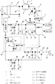
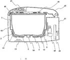
図1は、本発明の実施の形態1における誘導加熱式炊飯器の一部ブロック化した回路図を示し、図2は、同誘導加熱式炊飯器の断面図を示すものである。なお、図面を簡潔にするために、電気的接続のためのリード線や、部品を固定するためのネジは省略している。
(Embodiment 1)
FIG. 1 shows a partially blocked circuit diagram of the induction heating rice cooker in
図1に示すように、鍋1は銅、ステンレス、アルミなどの複数の金属からなるクラッド鋼板で構成している。加熱コイル2は鍋1を誘導加熱するもので、図示しないが線径の小さい銅線を束ねたリッツ線で構成している。共振用コンデンサ3は、加熱コイル2と並列共振回路を構成している。共振用コンデンサ3は、高周波電流が流れても損失が低いメタライズドポリエステルコンデンサを使用している。
As shown in FIG. 1, the
スイッチング手段4は、加熱コイル2を同通、遮断するもので、IGBT5とIGBT5に逆接続した逆接続ダイオード6で構成している。一般的にIGBTは高速スイッチングと大電流を流すことができる半導体素子である。IGBT5が高周波スイッチングをすることで、加熱コイル2に高周波電流が流れ、高周波磁界が発生する。
The switching means 4 communicates and blocks the
駆動手段7は、スイッチング手段4をオンオフするもので、本実施の形態では、特に図示をしていないが、PNPトランジスタとNPNトランジスタからなるプッシュプル回路で構成している。ダイオードブリッジ8とチョークコイル9とコンデンサ10は商用電源11を整流している。本実施の形態では、商用電源11の周波数は約50Hzとするが、別に60Hzでも構わない。
The driving means 7 turns on and off the switching means 4 and is configured by a push-pull circuit composed of a PNP transistor and an NPN transistor, although not particularly shown in the present embodiment. The
入力手段12は、複数のモーメンタリスイッチで構成しており、使用者が炊飯方法や炊飯の開始または停止などを選択することができる。表示手段13は、液晶ディスプレイやLEDで構成しており、使用者が設定した内容や、炊飯中、予約中などの炊飯器の状態、炊飯の経過時間を表示する。
The
制御手段14は、駆動手段7を通してスイッチング手段4をオンオフ制御するもので、特に図示しないが、マイクロコンピュータや鍋1の底部分の温度を検知するサーミスタ、商用電源11の電圧を検知する電圧検知回路、商用電源11から入力される入力電流を検知するカレントトランスなどで構成しており、スイッチング手段4のオンオフ制御や、入力手段7からの信号を受けて、LCD(表示手段13)に設定された内容を表示し、設定された内容に基づいて炊飯シーケンス、保温シーケンスを動作させる。
The control means 14 controls on / off of the switching means 4 through the driving means 7, and although not particularly shown, a microcomputer, a thermistor for detecting the temperature of the bottom portion of the
スピーカ15は、音声信号増幅回路24の出力信号を音声に変換するもので、特に図示しないが、本実施の形態では、巻線と磁石を用いて、巻線に流れる電流と磁石の磁界でコイルを振動させる構成にしている。なお、本実施の形態では、スピーカに流す電流を小さくするために、スピーカのインピーダンスを8Ωより大きくしている。なお、スピーカ15は入力端子のうちの一つをグランド電位に接続している。
The
音声信号出力手段16は、制御手段14の信号を受けて所定の音声信号を出力するもので、音声データを4bitデータとして記憶したメモリ17と、メモリ17から出力されるデジタル信号をアナログ信号に変換するDA変換器18を有する音声合成ICを用いた構成としている。フィルタ回路19は、抵抗20とコンデンサ21の直列回路からなるハイパスフィルタと、抵抗22とコンデンサ23の並列回路からなるローパスフィルタで構成しており、音声信号出力手段16の出力信号の低周波成分と高周波成分を減衰させる。
The audio
音声信号増幅回路24は、音声信号出力手段16の信号を増幅するもので、市販のオペアンプで構成しており、フィルタ回路19の出力電圧を所定の増幅率で増幅する。コンデンサ25は音声信号増幅回路25の出力信号のうち、直流成分を除去するもので、スピーカ15に直流電圧が印加しないようにしている。
The audio signal amplifier circuit 24 amplifies the signal of the audio signal output means 16 and is composed of a commercially available operational amplifier, and amplifies the output voltage of the
第1の直流電源26は、少なくともスイッチング手段4に電力を供給するもので、特に図示しないが、スイッチング電源で構成し、商用電源11を半波整流した電圧を約20Vの直流電源に変換している。第1の直流電源26の出力電圧20VはIGBT5をオンするために必要な電圧で、駆動手段7を介してIGBT5に供給され、IGBT5はオンする。
The first
第2の直流電源27は、NPNトランジスタ28と定電圧ダイオード29と抵抗30とコンデンサ31からなるエミッタフォロア回路で構成しており、第1の直流電源26より電力を供給され、第1の直流電源26を約5Vに降圧している。第2の直流電源27は、制御手段14を構成するマイクロコンピュータ、音声信号出力手段16を構成する音声合成ICの電源となっている。
The second
第3の直流電源32は、NPNトランジスタ33と定電圧ダイオード34と抵抗35とコンデンサ36からなるエミッタフォロア回路で構成しており、第1の直流電源26より電力を供給され、第1の直流電源26を約10Vに降圧している。第2の直流電源27と第3の直流電源32の電源電圧が異なるのは、スピーカ15に印加する電圧が約8Vと高いことと、スピーカ15を駆動するときにNPNトランジスタ33に流れる電流が大きいので、NPNトランジスタのコレクタエミッタ間の電圧を小さくし、発熱を減らすためである。
The third DC power source 32 is configured by an emitter follower circuit including an
スイッチ回路37は、抵抗内蔵型のPNPトランジスタ38とNPNトランジスタ39で構成されており、制御手段14からハイまたはローの信号を出力することで、第1の直流電源26と第3の直流電源27の電流経路を導通または遮断する。
The
ここで、制御手段14は音声を出力しないときはスイッチ回路37を遮断状態にして第3の直流電源32をオフし、音声信号増幅回路24への電源供給を停止するよう構成している。
Here, when the sound is not output, the control means 14 is configured to turn off the third DC power supply 32 by turning off the
冷却手段40は、スイッチング手段4を冷却するもので、本実施の形態では、ファンモータで構成している。このファンモータを駆動する電源は第1の直流電源26より供給され、制御手段14を構成するマイクロコンピュータよりオンオフ信号を送信することで、ファンモータをオンオフ制御する。
The cooling means 40 cools the switching means 4 and is constituted by a fan motor in the present embodiment. The power source for driving the fan motor is supplied from the first
つぎに、図2に示すように、炊飯器本体41は、その上面を覆う蓋42を開閉自在に設置している。炊飯器本体41の収納部43には、その底部に加熱コイル2を配設している。加熱コイル2の外周側にフェライトコア44を配設している。加熱コイル2は、鍋1の底部の中心が中心になるように渦巻状に巻かれた巻線である。
Next, as shown in FIG. 2, the rice cooker
鍋1は上端開口部に外側にせり出したフランジを有し、フランジを収納部43の上端から浮き上がった状態で載置することにより、収納部43に着脱自在に収納される。したがって、鍋1は収納時に収納部43との間に隙間を有する。鍋1の材質については、図1で説明したとおりであり、ここでは省略する。蓋42には着脱自在な蓋加熱板45を設定している。蓋加熱板45はステンレスなどの金属で形成している。蓋加熱コイル46は、図1では記載していないが、蓋42に内蔵され、蓋加熱板45を誘導加熱する。
The
第1の回路基板47は、入力手段12を構成するスイッチ、表示手段13を構成するLCD、LED、制御手段14を構成するマイクロコンピュータ、音声信号出力手段16を構成する音声合成IC、第3の直流電源32、スイッチ回路37などを実装している。第2の回路基板48は、スイッチング手段4や、駆動手段7、ダイオードブリッジ8、チョークコイル9、コンデンサ10、第1の直流電源26、第2の直流電源27などを実装している。スイッチング手段4とダイオードブリッジ8はアルミで成形された放熱フィンにねじ止めされており、この放熱フィンには冷却手段としてファンモータがねじ止めされている。
The
巻き取り式の電源コード収納部49は、第2の回路基板48にリード線を介して電気的に接続している。電源コード収納部49はストッパーとばねを用いて電源コードを巻き取ることを可能にしている。
The wind-up type
サーミスタ50は、鍋1の底部の略中心に配置し、鍋1の温度を検知している。本実施の形態では、サーミスタ50は制御手段14の一部を構成している。サーミスタ50は温度で抵抗値が変わるので、サーミスタ50と所定の抵抗値を有する抵抗で分圧回路を構成し、第2の直流電源27の電圧をこの分圧回路に供給することで、サーミスタ50の抵抗値をアナログ電圧に変換できる。図1に示した制御手段14を構成するマイクロコンピュータは、内蔵されたAD変換器を用いてこのアナログ電圧から温度を推定する。
The
第1の回路基板47と第2の回路基板48は、リード線で電気的に接続しており、図1に示した回路構成を実現している。
The
スピーカ15は、図2に示すように、炊飯器本体41と加熱コイル1の間にできる隙間を利用して配置し、加熱コイル1の下にスピーカ15の出力面を下向きに配置している。なお、スピーカ15の向きや配置場所については、特に限定するものではなく、スピーカ15の出力面を上向きにしてもよいし、スペースがあるのであれば、蓋42に配置してもかまわない。
As shown in FIG. 2, the
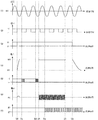
上記構成において図3を参照しながら動作、作用を説明する。なお、図3は、本実施の形態の音声出力時の主要部のタイミングチャートを示しており、(1)は商用電源11の電圧波形、(2)は商用電源11の0Vに同期してハイまたはローを出力する波形(図1には図示していない)、(3)はスイッチ回路37のオン(導通)、オフ(遮断)状態、(4)は第3の直流電源32の出力電圧波形、(5)は制御手段14から音声信号出力手段16への送信信号波形、(6)はスピーカ15の入力電圧、(7)はスイッチング手段4のオンオフ状態をそれぞれ示している。
The operation and action of the above configuration will be described with reference to FIG. FIG. 3 shows a timing chart of the main part at the time of audio output according to the present embodiment. (1) is a voltage waveform of the
まず、使用者が第1の回路基板47に設けたスイッチ(入力手段12)を操作すると、制御手段14が入力手段12の信号を検知する。すると、図3の時刻T0では、制御手段14は商用電源11のゼロ電圧に同期して、スイッチ回路37をオン状態にし、第3の直流電源32を起動し、音声信号増幅回路24へ直流電圧を供給する。このとき、第3の直流電源32の出力電圧変動するため、音声信号増幅回路24の出力電圧が変動し、この出力電圧の変動がコンデンサ25を介してスピーカ15に印加され、ノイズ音となって出力されることがある。
First, when the user operates a switch (input means 12) provided on the
その後、図3の時刻T1で、制御手段14は再び商用電源11のゼロ電圧に同期して音声信号出力手段16に音量設定データを送信する。その後、図3の時刻T2で、制御手段14は商用電源11のゼロ電圧に同期して所定の音声データを示したアドレスデータを、音声信号出力手段16に送信する。
Thereafter, at time T1 in FIG. 3, the
すると、図3の時刻T3で、音声信号出力手段16を構成するメモリ17が制御手段14からの送信データに基づいて、所定の音声のデジタルデータをDA変換器18に出力し、DA変換器18がアナログ電圧に変換された音声信号を出力し、フィルタ回路19、音声信号増幅回路24、コンデンサ25を介して、スピーカ15に音声信号が入力される。スピーカ15は音声信号が入力されると振動し、この振動が音声となって、使用者に音声報知する。このとき、この音声信号の低周波成分と高周波成分はフィルタ回路19で減衰され、減衰された音声信号が音声信号増幅回路24で増幅され、増幅された音声信号がコンデンサ25で直流成分を除去されている。
Then, at time T3 in FIG. 3, the
音声信号が出力されると、第3の直流電源32の電圧が約0.2V低下するが、第2の直流電源27の電圧は変動しないので、制御手段14を構成するAD変換器の基準電圧は変動しない。したがって、鍋1の温度検知、入力電流の検知、商用電源11の電圧検知など、AD変換器を利用した検知手段への影響を防止することができる。
When the audio signal is output, the voltage of the third DC power supply 32 decreases by about 0.2V, but the voltage of the second
図3の時刻T4では、入力手段12で設定されたメニューに従って、制御手段14が駆動手段7を介してスイッチング手段4のオンオフ制御を開始し、加熱コイル2に高周波電力を供給し、鍋1を加熱する。また、本実施の形態では、制御手段14は加熱コイル2を通電するのにあわせてファンモータ(冷却手段40)を駆動する。
At time T4 in FIG. 3, according to the menu set by the input means 12, the control means 14 starts on / off control of the switching means 4 via the drive means 7, supplies high-frequency power to the
図3の時刻T5で、音声出力が終了し、第3の直流電源32の出力電圧が元の値に戻る。図3の時刻T6で、制御手段14がスイッチ回路37を遮断し、第3の直流電源32への電力供給を停止する。第3の直流電源32が停止するので、音声信号増幅回路24への電力供給も停止することになり、消費電力を低減し、第1の直流電源26と、第3の直流電源32の発熱を抑えることができる。また、本実施の形態では、制御手段14は、予め音声データの時間を記憶しているので、その時間から所定時間を経過したら、スイッチ回路37を遮断するようにしている。スイッチ回路37の遮断タイミングを音声データの時間より十分に遅くするのは、音声信号出力手段16の出力する音声信号の速度にばらつきがあるためである。
At time T5 in FIG. 3, the audio output ends, and the output voltage of the third DC power supply 32 returns to the original value. At time T <b> 6 in FIG. 3, the
以上のように、本実施の形態では、駆動手段7に電力を供給する第1の直流電源26と、制御手段14に電力を供給する第2の直流電源27と、音声信号増幅回路24を介してスピーカに電力供給をする第3の直流電源32を設けることで、音声出力時に制御手段14の基準電圧が変動することを防止でき、鍋1の温度検知、入力電流の検知、商用電源11の電圧検知を精度よく行うことができる。
As described above, in the present embodiment, the first
また、本実施の形態では、音声を出力しないときはスイッチ回路37で第1の直流電源26から第3の直流電源32への電流経路を遮断しているので、第3の直流電源32の無負荷電流を抑えることになり、低電力化を実現している。また、余計な電流を流さないので、第1の直流電源26と第3の直流電源32の発熱も低減できる。
In the present embodiment, when the sound is not output, the
また、本実施の形態では、第1の直流電源26をスイッチング電源にしているが、この第1の直流電源26が立ち上がる際に出力電圧が変動した場合でも、スイッチ回路37により第3の直流電源32と音声信号増幅回路24をオフ状態にしているので、出力電圧の変動によるノイズ音がスピーカ15から出力されることがない。
In the present embodiment, the first
また、本実施の形態では、第1の直流電源26をスイッチング電源にしているので、第1の直流電源26の損失を減らし、低電力化を実現できる。さらに、第2の直流電源27と第3の直流電源32をエミッタフォロア回路で構成しているので、第1の直流電源26(スイッチング電源)からのスイッチングノイズを低減することができ、制御手段14の誤動作や、音声出力時のノイズ音を防止することができる。
In the present embodiment, since the first
また、本実施の形態では、スイッチング手段4をオンオフ制御する前に、制御手段14が音声信号出力手段16に送信するので、スイッチングノイズや加熱コイル2に流れる高周波電流で送信波形が変動するのを防止でき、音声を出力しないなどの誤動作を防止できる。
In the present embodiment, the control means 14 transmits to the audio signal output means 16 before the on / off control of the switching means 4, so that the transmission waveform fluctuates due to switching noise and high-frequency current flowing through the
また、本実施の形態では、冷却手段40を構成するファンモータの駆動用電源を第1の直流電源26から供給しているので、新たにファンモータを駆動する電源を必要としない。したがって、回路構成をコンパクトにすることができる。また、第1の直流電源26の出力電圧は約20Vであり、第2の直流電源27の約5V、第3の直流電源32の約10Vに比べ高い電圧を出力できる。したがって、ファンモータの出力が同じ場合、第1の直流電源26を使うと流す電流を一番少なくすることができ、第1の直流電源26の発熱を抑えることができる。
Further, in the present embodiment, since the driving power for the fan motor constituting the cooling means 40 is supplied from the first
なお、本実施の形態では、第2の直流電源27と第3の直流電源32をエミッタフォロア回路で構成しているが、第1の直流電源26と同様にスイッチング電源にしても構わない。この場合、電源回路の効率が高まり、電源回路の損失が減るので、スピーカ15に流す電流を増やしても電源回路が発熱しなくなり、その結果、スピーカ15から出力される音声の音量を大きくすることができる。
In the present embodiment, the second
(実施の形態2)
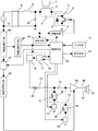
図4は、本発明の実施の形態2における誘導加熱式炊飯器の一部ブロック化した回路図を示すものである。
(Embodiment 2)
FIG. 4 shows a partially block circuit diagram of the induction heating rice cooker according to
図4に示すように、抵抗51とコンデンサ52は低周波成分を減衰させるハイパスフィルタを構成し、抵抗53とコンデンサ54は高周波成分を減衰させるローパスフィルタを構成している。また、オペアンプ55は入力信号を反転増幅し、オペアンプ56はオペアンプ55の出力を反転増幅している。オペアンプ56の増幅率は抵抗57、抵抗58の比率で決定している。オペアンプ55の増幅率は抵抗51と抵抗53の比率で決定している。オペアンプ55の出力端子は直流成分カット用のコンデンサ59を介してスピーカ15の一方の端子に接続している。オペアンプ56の出力端子はスピーカ15のもう一方の端子に接続している。60はオペアンプ55、56の基準電圧で、本実施の形態では、抵抗分圧回路で構成している。このように本実施の形態では、音声信号増幅回路を二つのオペアンプ55、56で構成している。
As shown in FIG. 4, the
第3の直流電源61は、図1に示した第3の直流電源と同じ回路構成であるが、出力電圧が約5Vとなっており、オペアンプ55、56だけでなく、音声信号出力手段16にも電力を供給している。
The third
電流制限手段62は、抵抗で構成し、スイッチ回路37と第3の直流電源61の電流経路に接続している。つまり、電流制限手段62は、第1の直流電源26から第3の直流電源61への電流経路に接続している。他の構成は、炊飯器の構成も含めて上記実施の形態1と同じであり、同一符号を付して説明を省略する。
The current limiting
上記構成において図5を参照しながら動作、作用を説明する。なお、図5は、本実施の形態の音声出力時の主要部のタイミングチャートを示しており、(1)は商用電源11の電圧波形、(2)は商用電源11の0Vに同期してハイまたはローを出力する波形(図1には特に図示していない)、(3)はスイッチ回路37のオン(導通)、オフ(遮断)状態、(4)は第3の直流電源61の出力電圧波形、(5)は制御手段14から音声信号出力手段16への送信信号波形、(6)はスピーカ15の入力電圧、(7)はスイッチング手段4のオンオフ状態、(8)は加熱コイル2に流れる高周波電流の包絡線をそれぞれ示している。
The operation and action of the above configuration will be described with reference to FIG. 5 shows a timing chart of the main part at the time of audio output of the present embodiment. (1) is a voltage waveform of the
まず、図5の時刻T0で、すでにスイッチング手段4をオンオフ制御し、加熱コイル2に高周波電流を流し、鍋1が加熱されている状態になっている。この状態で、使用者が第1の回路基板47に備えられたスイッチ(入力手段12)を操作すると、制御手段14が入力手段12の信号を検知する。すると、制御手段14は商用電源11のゼロ電圧に同期して、スイッチ回路37をオン状態にし、第3の直流電源61を起動し、オペアンプ55、56へ直流電圧を供給する。このとき、電流制限手段62により第3の直流電源61への電流が制限されるので、所定の電圧(約5V)に立ち上がるのに約20ms要している。
First, at time T0 in FIG. 5, the switching means 4 is already on / off controlled, a high-frequency current is supplied to the
つぎに、図5の時刻T1で、制御手段14は再び商用電源11のゼロ電圧に同期して音声信号出力手段16に音量設定データを送信する。制御手段14は、データを送信している間、スイッチング手段4をオフする信号を駆動手段7に送信し、駆動手段7がスイッチング手段4をオフ状態にしている。音声信号出力手段16へのデータ送信が終了すると、制御手段14は再びスイッチング手段4をオンオフ制御し、加熱コイル2に高周波電流を供給する。なお、データ送信速度は約32kbpsで、8bitのデータを送信しているので、スイッチング手段4をオフする期間は250μsである。
Next, at time T <b> 1 in FIG. 5, the
つぎに、図5の時刻T2で、制御手段14は商用電源11のゼロ電圧に同期して所定の音声データを示したアドレスデータを、音声信号出力手段16に送信する。このときも、時刻T1のときと同様に、音声信号出力手段16にデータ送信する間、スイッチング手段4をオフし、加熱コイル2に高周波電流を供給するのを停止する。
Next, at time T <b> 2 in FIG. 5, the
つぎに、図5の時刻T3で、音声信号出力手段16を構成するメモリ17が制御手段14からの送信データに基づいて、所定の音声のデジタルデータをDA変換器18に出力し、DA変換器18がアナログ電圧に変換された音声信号を出力し、オペアンプ55、56、コンデンサ57を介して、スピーカ15に音声信号が入力される。スピーカ15は音声信号が入力されると振動し、この振動が音声となって使用者に音声報知する。
Next, at time T3 in FIG. 5, the
音声信号が出力されると、第3の直流電源32の電圧が約0.2V低下するが、第2の直流電源27の電圧は変動しないので、制御手段14を構成するAD変換器の基準電圧は変動しない。したがって、鍋1の温度検知、入力電流の検知、商用電源11の電圧検知など、AD変換器を利用した検知手段への影響を防止することができる。
When the audio signal is output, the voltage of the third DC power supply 32 decreases by about 0.2V, but the voltage of the second
図5の時刻T4では、音声出力が終了し、第3の直流電源61の出力電圧が元の値に戻る。図5の時刻T5で、制御手段14がスイッチ回路37を遮断し、第3の直流電源61への電力供給を停止する。第3の直流電源61が停止するので、音声信号出力手段16、オペアンプ55、56への電力供給も停止することになり、消費電力が低減し、第1の直流電源26と、第3の直流電源61の発熱を抑えることができる。また、本実施の形態では、制御手段14は予め、音声データの時間を記憶しているので、その時間から所定時間を経過したら、スイッチ回路37を遮断するようにしている。スイッチ回路37の遮断タイミングを音声データの時間より十分に遅くするのは、音声信号出力手段16の出力する音声信号の速度にばらつきがあるためである。
At time T4 in FIG. 5, the audio output ends, and the output voltage of the third
以上のように、本実施の形態では、音声信号出力手段16に制御手段14がデータ送信する間、スイッチング手段4をオフすることにより、加熱コイル2に高周波電流が流れなくなるので、加熱コイル2による高周波ノイズが送信波形を乱して、音声を出力しないことや、本来のものとは異なる音声を出力することがなくなる。したがって、使用者がストレスなく使用できる信頼性の高い誘導加熱式炊飯器を提供できる。
As described above, in the present embodiment, since the
また、商用電源11の電圧が0V近傍のところでは、高周波電流が小さいので、高周波電流を停止しても、鍋1の加熱に与える影響が小さく、安定した加熱性能を得ることができる。
Moreover, since the high frequency current is small where the voltage of the
また、本実施の形態では、電流制限手段62で第3の直流電源61に供給する電流を制限しているので、第3の直流電源61の出力電圧が緩やかに上昇することになり、第3の直流電源61の電圧変動で、オペアンプ55、56の出力電圧が変動しても、スピーカ15に電圧が印加されなくなり、スピーカ15からノイズ音が発生しなくなる。
In the present embodiment, since the current supplied to the third
また、電流制限手段62を設けることで、過電流が第3の直流電源61、オペアンプ55、56、スピーカ15に流れ込まなくなるので、過電流による熱破壊や、高温動作による経年劣化速度が速くなることを抑えることができる。
In addition, by providing the current limiting
なお、本実施の形態では、電流制限手段62を抵抗で構成しているが、特に限定するものではない。例えば、定電流ダイオードを用いてもよい。また、第3の直流電源61を構成するNPNトランジスタのベース電流を制限することで電流を制限しても構わない。例えば、図1の回路構成図の場合では、第3の直流電源32を構成する抵抗35の値を変更することでNPNトランジスタ33のコレクタ電流の上限を変更できることになる。
In the present embodiment, the current limiting
なお、本実施の形態では、2つのオペアンプ55、56で音声信号増幅回路を構成している。2つのオペアンプ55、56を用いて、反転増幅をすることで、オペアンプ55、56の電源電圧と殆ど同じ電圧をスピーカ15に印加することができるので、オペアンプ55、56の電源電圧を下げて、音声信号出力手段16の電源電圧と同じにすることができる。したがって、音声出力時のみに使用する部品の電源を全てオフすることができるので、省電力化を実現できる。また、2つのオペアンプの出力電圧が殆ど同時に立ち上がるので、スピーカ15にオペアンプ55、56の電源がオンしたときのノイズ音が印加されることがなくなり、使用者に不快感を与えることがない。ただし、これは一例であり、1つのオペアンプで音声信号増幅回路を構成しても構わない。
In the present embodiment, the two
(実施の形態3)
図6は、本発明の実施の形態3における誘導加熱式炊飯器の一部ブロック化した回路図を示し、図7は、同誘導加熱式炊飯器の表示手段と入力手段の正面図を示すものである。
(Embodiment 3)
FIG. 6 shows a partially blocked circuit diagram of the induction heating rice cooker in
図6に示すように、抵抗71とコンデンサ72は第1のローパスフィルタ73を構成し、NPNトランジスタなどで構成される第1の切替手段(切替手段)74によりオンオフするようにしている。抵抗75とコンデンサ76は第2のローパスフィルタ77を構成し、NPNトランジスタなどで構成される第2の切替手段(切替手段)78によりオンオフするようにしている。第1のローパスフィルタ73の遮断周波数は第2のローパスフィルタ77の遮断周波数より高くしている。制御手段79は使用者が入力手段12で所定の音質(低音または高音)を選択すると、選択内容に応じて所定のローパスフィルタをオンする。
As shown in FIG. 6, the
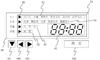
表示手段13は、図7に示すように、液晶装置91により構成し、音質表示部92、メニュー表示部93、お米表示部94、音量表示部95、選択内容表示部96、時刻表示部97などを有している。
As shown in FIG. 7, the display means 13 includes a
音質表示部92には、「高」「低」という項目が単独で表示可能となっている。本実施の形態では、「高」は高めの声で音声出力することを意味し、「低」は低めの声で音声出力することを意味している。メニュー表示部93には、「ふつう」「少量」「早炊き」「炊込み」「お手入れ」という5項目が単独で表示可能となっている。お米表示部94は、「白米」「無洗米」「玄米」「発芽玄米」「雑穀米」という5項目が単独で表示可能となっている。音量表示部95は、「大」「中」「小」という3項目が単独で表示可能となっている。選択内容表示部96は、右三角が4つ縦方向に配置されており、音質表示部92、メニュー表示部93、お米表示部94、音量表示部95のいずれかの内、設定可能な表示部の横にある右三角のみを表示する。時刻表示部97は、現在時刻を表示するだけでなく、炊飯炊き上がり時刻などを表示することができる。液晶囲い枠98は、プラスチックで構成しており、その表面に設定可能内容を印刷している。
The sound
入力手段12は、下三角キー99、左三角キー100、右三角キー101、確定キー102で構成している。それぞれのキーはモーメンタリスイッチで構成し、使用者が押すことで、図6の制御手段79に信号が入力される。
The input means 12 includes a
下三角キー99は、使用者が押すことにより選択内容表示部96の三角が1つずつ下方向に移動するキーである。左三角キー100は、使用者が押すことにより選択内容表示部96の三角が示している表示部で、選択された項目を左方向に1つずつ移動するキーである。右三角キー101は、使用者が押すことにより選択内容表示部96の三角が示している表示部で、選択された項目を右方向に1つずつ移動するキーである。確定キー102は、使用者が押すことにより、選択された項目を確定するキーである。他の構成は、炊飯器の構成も含めて上記実施の形態1と同じであり、同一符号を付して説明を省略する。
The
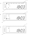
上記構成において図8を参照しながら動作、作用を説明する。なお、図8は、表示手段13の表示状態の一例を示したものである。 The operation and action of the above configuration will be described with reference to FIG. FIG. 8 shows an example of the display state of the display means 13.
図8(1)はメニュー選択中の表示状態を示している。選択内容表示部96は、選択可能な表示部を三角で示している。つまり、メニュー表示部93が選択されている。メニュー表示部93において、丸状の点線で囲まれた文字「ふつう」は点滅状態になっており、現在選択されていることを示している。お米表示部94、音量表示部95、音質表示部92は、現在選択されている内容のみを表示している。時刻表示部97は現在時刻を表示している。使用者は左三角キー100または右三角キー101でメニュー表示部内の項目を選択することができる。選択されている項目は点滅する。選択された項目を確定したい場合は、確定キー102を押せばよい。
FIG. 8A shows the display state during menu selection. The selection
図8(2)は音質選択中の表示状態を示している。(1)の状態から、使用者が下三角キー99を3回押すと(2)の表示状態となる。選択内容表示部96は選択可能な表示部を三角で示している。つまり、音質表示部92の項目が選択可能になっている。丸状の点線で囲まれた文字「低」は点滅状態になっており、現在選択されていることを示している。メニュー表示部93、お米表示部94、音量表示部95は、現在選択されている内容のみを表示している。選択内容表示部96は、設定可能な表示部のところのみを表示している。時刻表示部97は現在時刻を表示している。使用者は左三角キー100または右三角キー101で音質表示部92の項目「高」または「低」を選択し、確定キー102を押して確定する。本実施の形態では、音質表示部92の項目が「低」を選択している時に、確定キー102を押すと、図6の制御手段79は低音が選択されたと判断し、遮断周波数が低い第2のローパスフィルタを使う為に第2の切替手段77をオンし、第1の切替手段74をオフする。
FIG. 8 (2) shows a display state during sound quality selection. When the user presses the lower triangle key 99 three times from the state (1), the display state (2) is obtained. The selection
図8(3)は、何も操作していないときの表示手段の表示状態を示している。音質表示部92、メニュー表示部93、お米表示部94、音量表示部95は、現在設定されている内容を表示している。選択内容表示部96は、入力手段から何も信号が入力されないので、全て消灯した状態になっている。この状態から使用者が例えばメニューなどの項目を選択したいときは、下三角キー99または左三角キー100または右三角キー101を押す。すると選択内容表示部96の三角のうち、一番上の三角が表示され、選択可能な状態になる。
FIG. 8 (3) shows the display state of the display means when nothing is operated. The sound
初期設定では、調理中の台所を想定し、多少うるさい場所でも音声が通るように、遮断周波数を高くした第1のローパスフィルタ73が選択されている。しかし、例えば、炊飯器を使用している場所が比較的静かな場所だと、音声の高音部分が耳障りになるときがある。そのような場合、使用者は入力手段12で、図7、図8で示すように、音質を低音に選択する。すると制御手段79が第1の切替手段74をオフし、第1のローパスフィルタ73をオフするとともに、第2の切替手段78をオンし、第2のローパスフィルタ77をオンする。
In the initial setting, assuming that the kitchen is being cooked, the first low-
第2のローパスフィルタ77の遮断周波数は、第1のローパスフィルタ73より低いので、高周波成分が除去され、高音部分の音量が低減し、使用者の不快感を低減できる。
Since the cutoff frequency of the second low-
使用環境以外にも、使用者の年齢により、聞きやすさが異なる。例えば、本実施の形態では高齢者でも聞きやすいように、遮断周波数を高くし、高音の音量を大きくしているが、若年者の場合、この高音が耳障りになるときがある。この場合にも、使用者が入力手段12で音質を低音に選択すると、第2のローパスフィルタ77が選択され、耳障りな高音の音量が低減する。
In addition to the usage environment, the ease of listening varies depending on the age of the user. For example, in this embodiment, the cutoff frequency is increased and the volume of treble is increased so that even an elderly person can easily hear. However, in the case of a younger person, the treble may be annoying. Also in this case, when the user selects the sound quality to be low with the input means 12, the second low-
以上のように、本実施の形態では、周波数特性の異なる2つのフィルタ回路を設け、高音側と低音側に切り替えることで、使用環境、年齢に対応した快適な聞きやすい音声を提供することができる。また、現在設定されている音質が「低音」か「高音」かがわかるように表示手段13で表示するので、使用者がどちらの音質か確認することができ、使用環境や使用者の年齢に応じた音質に自由に設定できる。 As described above, in the present embodiment, two filter circuits having different frequency characteristics are provided, and switching between the high-pitched sound side and the low-pitched sound side can provide comfortable and easy-to-hear sound corresponding to the use environment and age. . In addition, since the display means 13 displays so that the currently set sound quality can be understood as “low sound” or “high sound”, the user can check which sound quality, and the use environment and the age of the user can be determined. The sound quality can be set freely.
なお、本実施の形態では、2つのフィルタ回路としたが、2つに限定するものではない。また、音声信号出力手段のメモリに周波数特性の異なる音声データを予め記憶しておき、使用者が好きな周波数特性の音声データを選択できるようにしてもよい。 In the present embodiment, two filter circuits are used, but the number of filter circuits is not limited to two. Alternatively, audio data having different frequency characteristics may be stored in advance in the memory of the audio signal output means so that the user can select audio data having a frequency characteristic that the user likes.
以上のように、本発明にかかる誘導加熱式炊飯器は、制御手段に電力を供給する第2の直流電源と、音声信号増幅回路に電力を供給する第3の直流電源とを分けることで、音声出力時の電源電圧変動により、制御手段の基準電圧が変動するのを防止することができ、音声の出力に関わらず制御手段への入力電圧の検知精度を維持することができるので、音声報知機能を有する誘導加熱式炊飯器として有用である。 As described above, the induction heating rice cooker according to the present invention separates the second DC power source that supplies power to the control means and the third DC power source that supplies power to the audio signal amplifier circuit, It is possible to prevent the reference voltage of the control means from fluctuating due to fluctuations in the power supply voltage at the time of voice output, and the accuracy of detection of the input voltage to the control means can be maintained regardless of the voice output. It is useful as an induction heating rice cooker having a function.
1 鍋
2 加熱コイル
4 スイッチング手段
7 駆動手段
14 制御手段
15 スピーカ
16 音声信号出力手段
24 音声信号増幅回路
26 第1の直流電源
27 第2の直流電源
32 第3の直流電源
37 スイッチ回路
DESCRIPTION OF
Claims (10)
Priority Applications (1)
| Application Number | Priority Date | Filing Date | Title |
|---|---|---|---|
| JP2006237231A JP4961908B2 (en) | 2006-09-01 | 2006-09-01 | Induction heating rice cooker |
Applications Claiming Priority (1)
| Application Number | Priority Date | Filing Date | Title |
|---|---|---|---|
| JP2006237231A JP4961908B2 (en) | 2006-09-01 | 2006-09-01 | Induction heating rice cooker |
Publications (2)
| Publication Number | Publication Date |
|---|---|
| JP2008055017A JP2008055017A (en) | 2008-03-13 |
| JP4961908B2 true JP4961908B2 (en) | 2012-06-27 |
Family
ID=39238453
Family Applications (1)
| Application Number | Title | Priority Date | Filing Date |
|---|---|---|---|
| JP2006237231A Active JP4961908B2 (en) | 2006-09-01 | 2006-09-01 | Induction heating rice cooker |
Country Status (1)
| Country | Link |
|---|---|
| JP (1) | JP4961908B2 (en) |
Families Citing this family (4)
| Publication number | Priority date | Publication date | Assignee | Title |
|---|---|---|---|---|
| JP5315826B2 (en) * | 2008-07-16 | 2013-10-16 | パナソニック株式会社 | Induction heating rice cooker |
| JP5726446B2 (en) * | 2010-07-01 | 2015-06-03 | 京セラ株式会社 | Portable electronic devices |
| CN103135055B (en) * | 2013-02-04 | 2015-04-22 | 丰唐物联技术(深圳)有限公司 | Method of distinguishing type of external-connection switch of intelligent device |
| JP6820765B2 (en) * | 2017-02-28 | 2021-01-27 | 三菱電機株式会社 | Cooker |
Family Cites Families (9)
| Publication number | Priority date | Publication date | Assignee | Title |
|---|---|---|---|---|
| JPS5896443A (en) * | 1981-12-04 | 1983-06-08 | Matsushita Electric Ind Co Ltd | automatic dialing device |
| JPS594828A (en) * | 1982-06-30 | 1984-01-11 | Sanyo Electric Co Ltd | Cooking unit |
| JPS5942794A (en) * | 1982-09-01 | 1984-03-09 | 三洋電機株式会社 | Electronic range |
| JPH01109683A (en) * | 1987-10-22 | 1989-04-26 | Matsushita Electric Ind Co Ltd | Power circuit |
| JP2805169B2 (en) * | 1990-04-16 | 1998-09-30 | 株式会社日立ホームテック | Electric cooker |
| JP3460614B2 (en) * | 1999-03-15 | 2003-10-27 | 松下電器産業株式会社 | Electric cooker |
| JP2002323222A (en) * | 2001-04-23 | 2002-11-08 | Toshiba Corp | microwave |
| JP4363315B2 (en) * | 2004-11-30 | 2009-11-11 | パナソニック株式会社 | Induction heating device |
| JP4961844B2 (en) * | 2006-06-09 | 2012-06-27 | パナソニック株式会社 | Induction heating rice cooker |
-
2006
- 2006-09-01 JP JP2006237231A patent/JP4961908B2/en active Active
Also Published As
| Publication number | Publication date |
|---|---|
| JP2008055017A (en) | 2008-03-13 |
Similar Documents
| Publication | Publication Date | Title |
|---|---|---|
| KR102674808B1 (en) | Audio apparatus and control method thereof | |
| JP4961908B2 (en) | Induction heating rice cooker | |
| US9313830B2 (en) | Induction heating cooker and control circuit therefor | |
| CN112565976B (en) | Speaker driving circuit, temperature protection method, terminal device, and storage medium | |
| JP5315826B2 (en) | Induction heating rice cooker | |
| JP4961844B2 (en) | Induction heating rice cooker | |
| JP4940836B2 (en) | Induction heating rice cooker | |
| JP2015225797A (en) | Induction heating apparatus | |
| JP6083668B2 (en) | Switching power supply circuit | |
| JP2011034904A (en) | Induction heating cooker | |
| JP2009000254A (en) | Electric rice cooker | |
| JPH04292889A (en) | Induction heating cooker | |
| JPS59123187A (en) | Electromagnetic induction heating cooking device | |
| JPS6046465A (en) | Meter drive circuit | |
| JPS62263472A (en) | Completion alarm for machinery | |
| JP3403087B2 (en) | Electromagnetic cooker | |
| JP4889536B2 (en) | Induction heating cooker | |
| JP4915081B2 (en) | rice cooker | |
| JP2008173150A (en) | Induction heating rice cooker | |
| EP3996268A1 (en) | Power conversion device | |
| JP5076508B2 (en) | Induction heating rice cooker | |
| JP2009106408A (en) | Induction heating rice cooker | |
| JP3191480B2 (en) | Inverter control device | |
| JP2007035528A (en) | Induction heating device | |
| CN202721596U (en) | A displaying numerical control electrostatic generator with adjustable frequency |
Legal Events
| Date | Code | Title | Description |
|---|---|---|---|
| A621 | Written request for application examination |
Free format text: JAPANESE INTERMEDIATE CODE: A621 Effective date: 20090407 |
|
| RD01 | Notification of change of attorney |
Free format text: JAPANESE INTERMEDIATE CODE: A7421 Effective date: 20090513 |
|
| A977 | Report on retrieval |
Free format text: JAPANESE INTERMEDIATE CODE: A971007 Effective date: 20110729 |
|
| A131 | Notification of reasons for refusal |
Free format text: JAPANESE INTERMEDIATE CODE: A131 Effective date: 20110809 |
|
| TRDD | Decision of grant or rejection written | ||
| A01 | Written decision to grant a patent or to grant a registration (utility model) |
Free format text: JAPANESE INTERMEDIATE CODE: A01 Effective date: 20120228 |
|
| A01 | Written decision to grant a patent or to grant a registration (utility model) |
Free format text: JAPANESE INTERMEDIATE CODE: A01 |
|
| A61 | First payment of annual fees (during grant procedure) |
Free format text: JAPANESE INTERMEDIATE CODE: A61 Effective date: 20120312 |
|
| R151 | Written notification of patent or utility model registration |
Ref document number: 4961908 Country of ref document: JP Free format text: JAPANESE INTERMEDIATE CODE: R151 |
|
| FPAY | Renewal fee payment (event date is renewal date of database) |
Free format text: PAYMENT UNTIL: 20150406 Year of fee payment: 3 |