JP4961704B2 - LED drive circuit - Google Patents
LED drive circuit Download PDFInfo
- Publication number
- JP4961704B2 JP4961704B2 JP2005275245A JP2005275245A JP4961704B2 JP 4961704 B2 JP4961704 B2 JP 4961704B2 JP 2005275245 A JP2005275245 A JP 2005275245A JP 2005275245 A JP2005275245 A JP 2005275245A JP 4961704 B2 JP4961704 B2 JP 4961704B2
- Authority
- JP
- Japan
- Prior art keywords
- led
- circuit
- voltage
- transistor
- current
- Prior art date
- Legal status (The legal status is an assumption and is not a legal conclusion. Google has not performed a legal analysis and makes no representation as to the accuracy of the status listed.)
- Expired - Fee Related
Links
Images


Description
本発明は、LEDの駆動回路に関し、より詳しくは遊技機の装飾に用いられるLEDの駆動回路に関する。 The present invention relates to an LED drive circuit, and more particularly to an LED drive circuit used for decoration of a gaming machine.
パチンコ遊技機や回胴遊技機に代表される遊技機では、遊技性と、遊技者に与える印象度合で顧客の満足度が左右され、遊技機の販売台数に影響が生じる。したがって、遊技機に組み込まれる表示装置の表示内容、効果音、役物動作などの演出を駆使して、如何に遊技者に魅力を与えるかが重要となる。 In gaming machines typified by pachinko gaming machines and spinning-reel gaming machines, the degree of customer satisfaction is influenced by the gaming performance and the impression level given to the player, and the number of gaming machines sold is affected. Therefore, it is important how to make the player attractive by making full use of effects such as the display contents of the display device incorporated in the gaming machine, sound effects, and accessory actions.
このような演出の一つとして、光装飾があり、遊技機の遊技盤前面にLED、ランプなどの発光体を多数配置し、それぞれ個別に駆動することで演出効果を高めている。例えば、待機中、通常遊技中、大役中など、遊技の状況に応じて、発光体の点灯パターンや輝度を変化させて、遊技者に大役の期待を抱かせる工夫を施している。 As one of such effects, there is a light decoration, and a large number of light emitters such as LEDs and lamps are arranged on the front surface of the game board of the gaming machine and are individually driven to enhance the effect. For example, ingenuity has been devised to change the lighting pattern and brightness of the light emitters according to the state of the game, such as during standby, during normal games, and during major roles, so that the player can have the expectation of major players.
このような光装飾の用途で用いられるLEDとしては、赤色、緑色、及び青色が代表的であり、これらのLEDを適切に配置し、それぞれの発光量を制御することによって、遊技者に対して多様な発色光で発光しているように見せることができる。また、例えば大役中若しくはリーチ中などの場合では、LEDの発光量、点滅速度などを急激に変化させることにより、明らかに待機中とは異なる視覚認識を遊技者にもたせて、遊技者の期待感や達成感を高めるように演出することができる。 Typical examples of LEDs used in such light decoration applications are red, green, and blue. By appropriately arranging these LEDs and controlling the amount of light emitted from each of them, it is possible for the player. It can appear to emit light with various colored light. Also, for example, when playing a big role or during a reach, the player's sense of expectation is clearly given to the player by visually changing the amount of light emitted, the blinking speed, etc., clearly different from the standby state. And can produce a sense of achievement.
また近年、遊技機では、演出効果を高めるために、より高輝度のLEDが用いられるようになってきている。一方、このような高輝度LEDを用いた場合、平均的な環境下でのパチンコホールにおいて、遊技者がLEDの明るさの違いを認識できるように発光量の調整を行うためには、LEDに流れる電流を、最大定格電流値と比較して微弱な電流値の範囲で変化させることが必要である。そのような制御を行うために、遊技盤に配置されたLEDは、配線を介して演出用CPUに接続されるLED駆動回路によって制御され、演出用CPUからの出力信号の変化に応じて点灯又は消灯動作を行う。 In recent years, in gaming machines, higher brightness LEDs have been used in order to enhance the effect. On the other hand, when such a high-brightness LED is used, in the pachinko hall under an average environment, in order to adjust the light emission amount so that the player can recognize the difference in the brightness of the LED, It is necessary to change the flowing current in a range of a weak current value as compared with the maximum rated current value. In order to perform such control, the LED arranged on the game board is controlled by an LED drive circuit connected to the effect CPU via wiring, and is turned on or off according to a change in the output signal from the effect CPU. Turns off the light.
このような目的に使用可能なLED駆動回路として、外部端子からの入力信号により制御して、LEDの光出力を可変調整可能なインジケータ減光システム及びLED駆動回路が開発されている(特許文献1及び2参照)。 As an LED drive circuit that can be used for such a purpose, an indicator dimming system and an LED drive circuit have been developed that can be controlled by an input signal from an external terminal to variably adjust the light output of the LED (Patent Document 1). And 2).
特許文献1に記載されたインジケータ減光システムは、LED駆動用の第1のスイッチング素子と、LEDに流れる電流を規定する電流制限抵抗と、電流制限抵抗の抵抗値を切り替える第2のスイッチング素子と、第1と第2のスイッチング素子を制御するマイクロプロセッサを有する(特許文献1参照)。そして、マイクロプロセッサからの制御信号によって、第1のスイッチング素子及び第2のスイッチング素子を選択的にバイアスすることにより、LEDの消灯及び発光輝度の切り替えを行うものである。
The indicator dimming system described in
しかしながら、特許文献1に記載されたインジケータ減光システムでは、LEDの発光輝度自体は2段階にしか切り替えられず、それよりも多階調でLEDの発光輝度を変化させることはできない。
However, in the indicator dimming system described in
また、特許文献2に記載されたLED駆動回路は、制御信号によって出力電圧がON/OFFする複数の定電圧電源と、その複数の定電圧電源の出力をベースに、電源端子をコレクタを接続する同数の回路切替用トランジスタと、回路切替用トランジスタのエミッタのそれぞれに一端を接続し、他端を共通にしてLEDのアノードに接続する抵抗器とよりなる切替回路を有する。そしてこのLED駆動回路では、複数の定電圧電源のうち、出力電圧がONになったものでバイアスされる回路切替用トランジスタを通じてのみ、LEDに駆動電流が流れるため、定電圧電源に対する制御信号によって、LEDの発光量を変化させることができる。
In addition, the LED driving circuit described in
しかしながら、特許文献2に記載されたLED駆動回路では、LEDの発光量の段階数を増やすためには、その段階数に応じて定電圧電源、回路切替用トランジスタ及び抵抗器の数を増加させることが必要である。そのため、遊技機の光装飾に用いるLED駆動回路としては、高価なものとなってしまい、また必要な配線の量も非常に多くなり、設置に要する面積の増大やノイズの発生などの面でも望ましくない。
However, in the LED driving circuit described in
またパチンコ機の表示装置用LEDの駆動装置として、パルス幅変調(PWM)方式を用いたものも知られている(特許文献3参照)。PWM制御では、CPUからの出力信号を方形波のパルスとして、そのデューティ比を変化させることでLEDに流れる平均電流値を調整し、LEDの発光量を調整する。 In addition, a device using a pulse width modulation (PWM) method is known as a driving device for a display device LED of a pachinko machine (see Patent Document 3). In the PWM control, the output signal from the CPU is a square wave pulse, and the duty ratio is changed to adjust the average current value flowing through the LED, thereby adjusting the light emission amount of the LED.
しかし、PWM方式を採用する場合、特に相対的に小さい発光量で多段階にLEDの発光量を変化させようとすると、デューティ比をわずかに変更するような制御を行わなければならず、そのため細かいサンプリングピッチで出力波形を形成することが必要となる。したがって、そのためCPUの負荷が大きく、演出用CPUとして、高価で高性能なCPUを用いるか、演出用CPUとは別個に、LEDの制御専用のCPUを備えることが必要となり、高コストとなってしまう。 However, when adopting the PWM method, especially when trying to change the light emission amount of the LED in a multistage manner with a relatively small light emission amount, it is necessary to perform a control that slightly changes the duty ratio. It is necessary to form the output waveform at the sampling pitch. Therefore, the load on the CPU is large, and it is necessary to use an expensive and high-performance CPU as the production CPU, or to provide a CPU dedicated to LED control separately from the production CPU. End up.
また、特許文献3に記載されたパチンコ機では、少ない配線で多数のLEDを駆動するために、一部の信号線を共通化している。しかし、そのために各LEDに対して、電源供給が停止する期間が生じてしまい、LEDを最大輝度で持続して発光させることが不可能となり、遊技者が感じる明るさも低下してしまう。また遊技者がそれ程明るいと感じない程度の発光しかできなければ、遊技者に与えるインパクトも希薄なものとなり、十分な演出効果を発揮することが困難となる。
Further, in the pachinko machine described in
上記の問題点に鑑み、本発明は、LEDの発光量を多段階に調整可能なLED駆動回路を提供することを目的とする。 In view of the above problems, an object of the present invention is to provide an LED drive circuit capable of adjusting the light emission amount of an LED in multiple stages.
また本発明の別の目的として、LEDを相対的に低い発光量で多段階に調整可能であり、且つ相対的に大きな発光量に調整も可能なLED駆動回路を提供することを目的とする。 Another object of the present invention is to provide an LED drive circuit that can adjust LEDs in multiple stages with a relatively low light emission amount and that can also adjust the light emission amount to a relatively large amount.
本発明のさらに別の目的として、制御用のCPUの負荷を軽減可能なLED駆動回路を提供することを目的とする。 Still another object of the present invention is to provide an LED drive circuit capable of reducing the load on a control CPU.
上記の目的を達成するために、本発明に係る定電圧源に接続されたLEDに流れる駆動電流を制御するLED駆動回路は、可変電圧を印加する電圧印加回路と、第1のトランジスタと、LEDと直列に接続される抵抗とを有する第1の電流制御回路であって、第1のトランジスタのベース端子を介して電圧印加回路と接続され、かつ、第1のトランジスタのエミッタ端子またはコレクタ端子を介してLEDと接続される第1の電流制御回路と、電圧印加回路に対して第1の電流制御回路と並列に接続される電圧降下素子と、第2のトランジスタを有する第2の電流制御回路であって、電圧降下素子及び第2のトランジスタのベース端子を介して電圧印加回路と接続され、かつ、第2のトランジスタのエミッタ端子またはコレクタ端子を介してLEDと接続される第2の電流制御回路とを有することを特徴とする。 In order to achieve the above object, an LED driving circuit for controlling a driving current flowing in an LED connected to a constant voltage source according to the present invention includes a voltage applying circuit for applying a variable voltage, a first transistor, an LED A first current control circuit having a resistance connected in series to the voltage application circuit via a base terminal of the first transistor, and an emitter terminal or a collector terminal of the first transistor A second current control circuit having a first current control circuit connected to the LED via the voltage application circuit, a voltage drop element connected in parallel with the first current control circuit with respect to the voltage application circuit, and a second transistor And connected to a voltage application circuit via the voltage drop element and the base terminal of the second transistor, and via the emitter terminal or collector terminal of the second transistor. And having a second current control circuit connected to the ED.
このような構成とすることにより、第1の駆動電流によってLEDを制御する場合には、所望の輝度の範囲でLEDの発光輝度を調整できるようにするとともに、第2の駆動電流によってLEDを制御する場合には、LEDを所定の輝度、例えば最大輝度で発光させることができる。なお、上記において電圧印加回路は、第1及び第2の電流制御回路に対して、直接的に電圧を印加するものだけでなく、他の回路を通じて間接的に電圧を印加するものも含む。 With this configuration, when the LED is controlled by the first drive current, the light emission luminance of the LED can be adjusted within a desired luminance range, and the LED is controlled by the second drive current. In this case, the LED can emit light with a predetermined luminance, for example, maximum luminance. In the above, the voltage application circuit includes not only a voltage applied directly to the first and second current control circuits but also a voltage applied indirectly through another circuit.
また、電圧印加回路によって印加される電圧が第1の電圧以上のとき、第1の電流制御回路は第1の駆動電流を生成し、電圧印加回路によって印加される電圧が第2の電圧以上のとき、第2の電流制御回路は第2の駆動電流を生成し、且つ第2の電圧が第1の電圧よりも高いことが好ましい。このように、第1の電流制御回路がアクティブとなる電圧と第2の電流制御回路がアクティブとなる電圧が異なることで、一つの電圧印加回路だけを用いて、第1の電流制御回路と第2の電流制御回路を別個に駆動することができる。 Further, when the voltage applied by the voltage application circuit is equal to or higher than the first voltage, the first current control circuit generates a first drive current, and the voltage applied by the voltage application circuit is equal to or higher than the second voltage. When the second current control circuit generates the second drive current, the second voltage is preferably higher than the first voltage. In this way, the voltage at which the first current control circuit becomes active and the voltage at which the second current control circuit becomes active are different, so that only one voltage application circuit is used to The two current control circuits can be driven separately.
また、第1の駆動電流の最大値が、第2の駆動電流の1/10以下であることが好ましい。第1の駆動電流を、相対的に小さな電流値の範囲に限定して調整幅を狭くすることによって、LEDを最大発光輝度に対して相対的に低輝度の領域においても正確に輝度調整することが可能となるためである。また、上限を1/10とすれば、詳しくは後述する図1から分かるように、第9階調までは第1の駆動電流でカバーできるため、LEDの明るさを等間隔でも5段階に分けて表現することができる。 The maximum value of the first drive current is preferably 1/10 or less of the second drive current. By limiting the first drive current to a relatively small current value range and narrowing the adjustment range, the brightness of the LED can be accurately adjusted even in a region where the brightness is relatively low with respect to the maximum light emission brightness. This is because it becomes possible. Further, if the upper limit is 1/10, as can be seen from FIG. 1 to be described in detail later, the first drive current can be covered up to the ninth gradation, so that the brightness of the LED is divided into five stages evenly spaced. Can be expressed.
なお、第1の電流制御回路は、第1のトランジスタを有し、第2の電流制御回路は、第2のトランジスタを有し、第1のトランジスタと第2のトランジスタが、ダーリントン接続されていることが好ましい。ダイオードのようなスイッチング素子を別途設けなくとも、第1のトランジスタがバイアスされる電圧と第2のトランジスタがバイアスされる電圧を変えることができるため、回路構成を簡単化することができる。 Note that the first current control circuit includes a first transistor, the second current control circuit includes a second transistor, and the first transistor and the second transistor are Darlington-connected. It is preferable. Without separately providing a switching element such as a diode, the voltage at which the first transistor is biased and the voltage at which the second transistor is biased can be changed, so that the circuit configuration can be simplified.
さらに、電圧印加回路は、デューティ比を変更可能な方形波パルス電源と、方形波パルス電源と第1の電流制御回路との間に接続される充放電回路を有することが好ましい。CPUでの制御が容易な、又はCPUからの出力自体を電源出力とみなせる方形波パルス電源を用いることが可能であるとともに、方形波パルスをそのデューティ比に依存してピーク電圧の変わるパルスに変更する充放電回路を備えたことにより、図1に示す第7階調以下のような相対的に暗い領域でも、デューティ比を1%の以下の細かい範囲で調整することなくLEDの明るさを調整できるため、演出用CPUの負荷を軽減することが可能となる。 Furthermore, it is preferable that the voltage application circuit includes a square wave pulse power supply capable of changing a duty ratio, and a charge / discharge circuit connected between the square wave pulse power supply and the first current control circuit. It is possible to use a square wave pulse power supply that can be easily controlled by the CPU, or the output from the CPU itself can be regarded as a power supply output, and the square wave pulse is changed to a pulse whose peak voltage changes depending on its duty ratio. By providing a charging / discharging circuit that adjusts the brightness of the LEDs without adjusting the duty ratio in a fine range of 1% or less even in a relatively dark region such as the seventh gradation or less shown in FIG. Therefore, it is possible to reduce the load on the effect CPU.
または、電圧印加回路は、互いに発振周波数の異なる第1及び第2のパルス列を出力する発振回路と、第1及び第2のパルス列を入力とし、第1のパルス列と第2のパルス列の電圧の高低の比較結果に基づいた電圧を出力する比較器と、比較器の出力端子と第1の電流制御回路との間に接続される充放電回路を有することが好ましい。さらに、充放電回路と第1の電流制御回路との間に接続され、外部信号入力端子を有する信号入力回路を有し、その信号入力回路は、外部信号入力端子に所定の電圧が印加されると、第1及び第2の電流制御回路の動作状況を変化させる。 Alternatively, the voltage application circuit has an oscillation circuit that outputs the first and second pulse trains having different oscillation frequencies and the first and second pulse trains as inputs, and the voltages of the first pulse train and the second pulse train are increased or decreased. It is preferable to have a comparator that outputs a voltage based on the comparison result, and a charge / discharge circuit connected between the output terminal of the comparator and the first current control circuit. Furthermore, it has a signal input circuit connected between the charge / discharge circuit and the first current control circuit and having an external signal input terminal, and the signal input circuit applies a predetermined voltage to the external signal input terminal. Then, the operation states of the first and second current control circuits are changed.
このような構成とすることで、演出用CPUは、LEDを消灯若しくは最大輝度点灯という特定の状態を出現させる場合のみ制御信号を与えるだけで、通常の状態と区別することができ、演出用CPUに対する負荷を軽減しつつ演出効果の高いLED駆動回路を構成することができる。 With such a configuration, the effect CPU can be distinguished from the normal state only by giving a control signal only when a specific state of turning off the LED or turning on the maximum brightness appears. Thus, it is possible to configure an LED drive circuit with a high effect of production while reducing the load.
また本発明に係るLED駆動システムは、上記の外部信号入力端子を有する第1のLED駆動回路及び第2のLED駆動回路と、第1及び第2の入力端子と出力端子を有し、出力端子が第1のLED駆動回路の外部信号入力端子に接続される第1の合成回路と、第3及び第4の入力端子と出力端子を有し、出力端子が第2のLED駆動回路の外部信号入力端子に接続される第2の合成回路と、直列に接続される第1及び第2のメモリを有するシフトレジスタとを有し、第1の入力端子には、第1のメモリの出力が接続され、第3の入力端子には、第2のメモリの出力が接続され、且つ第2の入力端子及び第4の入力端子には、同一の制御信号が与えられることを特徴とする。
このような構成とすることで、駆動するLEDの数が多い場合でも、LED駆動システムに制御信号を供給するCPUにおいて、必要な出力端子数を少なくすることができ、省配線化することができる。
The LED driving system according to the present invention includes a first LED driving circuit and a second LED driving circuit having the external signal input terminal, a first input terminal and an output terminal, and an output terminal. Has a first synthesis circuit connected to an external signal input terminal of the first LED drive circuit, a third and a fourth input terminal, and an output terminal, and the output terminal is an external signal of the second LED drive circuit A second synthesis circuit connected to the input terminal; and a shift register having first and second memories connected in series. The output of the first memory is connected to the first input terminal. The output of the second memory is connected to the third input terminal, and the same control signal is applied to the second input terminal and the fourth input terminal.
With such a configuration, even when the number of LEDs to be driven is large, the number of output terminals required in the CPU that supplies a control signal to the LED driving system can be reduced, and wiring can be saved. .
また、上記のLED駆動回路又はLED駆動システムは、半導体集積回路としてパッケージングしてもよい。 Further, the LED driving circuit or the LED driving system may be packaged as a semiconductor integrated circuit.
さらに、本発明に係る遊技機は、上記のLED駆動回路又はLED駆動システムを有することを特徴とする。ここで遊技機とは、パチンコ遊技機及び回胴式遊技機をいう。 Furthermore, a gaming machine according to the present invention has the above LED drive circuit or LED drive system. Here, the gaming machine refers to a pachinko gaming machine and a revolving type gaming machine.
本発明によれば、LEDの発光量を多段階に調整可能なLED駆動回路を提供することが可能となる。 ADVANTAGE OF THE INVENTION According to this invention, it becomes possible to provide the LED drive circuit which can adjust the light emission amount of LED in multistep.
また、LEDを相対的に低い発光量で多段階に調整可能であり、且つ相対的に大きな発光量に調整も可能なLED駆動回路を提供することが可能となる。 In addition, it is possible to provide an LED drive circuit that can adjust LEDs in multiple steps with a relatively low light emission amount, and can also adjust the LED to a relatively large light emission amount.
さらに、制御用のCPUの負荷を軽減可能なLED駆動回路を提供することが可能となる。 Furthermore, it is possible to provide an LED drive circuit that can reduce the load on the control CPU.
まず、遊技機の光装飾で使用するLEDを、どの程度の発光量で制御すれば高い演出効果を得られるか知るために、本願発明者は、遊技機に通常使用されるLEDについて、ホール環境で遊技者がLED発光の明るさの違いを認識可能な発光量について調査を行った。その調査結果について説明する。なおこの調査では、最大輝度7700mcdの赤色LEDを用いた。 First, in order to know how much light output can be used to control the LED used in the light decoration of the gaming machine, the inventor of the present application can use the hall environment for the LED normally used in the gaming machine. The player investigated the amount of light that can be recognized by the player to recognize the difference in brightness of the LED light. The survey results will be described. In this investigation, a red LED having a maximum luminance of 7700 mcd was used.
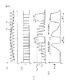
図1は、屋内において、50cmの距離でLEDの目視観察を行い、消灯状態からLEDの最大輝度での定常発光状態まで、LEDの明るさが等間隔で11段階変化したと観察者が感じるように、LEDをPWM制御した場合の、LEDに印加するパルス電圧のデューティ比の変化を示す。図1において横軸は階調を表し、第1階調は消灯状態、第11階調は最大輝度での定常発光状態を表す。また、縦軸はデューティ比を表す。 FIG. 1 shows that an LED is observed indoors at a distance of 50 cm, and the observer feels that the brightness of the LED has changed 11 steps at regular intervals from the extinguished state to the steady light emitting state at the maximum luminance of the LED. Fig. 5 shows changes in the duty ratio of the pulse voltage applied to the LED when the LED is PWM-controlled. In FIG. 1, the horizontal axis represents gradation, the first gradation represents a light-off state, and the eleventh gradation represents a steady light emission state at the maximum luminance. The vertical axis represents the duty ratio.
図1に示されるように、第2階調では、デューティ比は0.03%にすぎず、消灯状態と定常発光状態の中間にあたる第6階調においても、デューティ比は0.6%しかなく、その次の第7階調で漸く1%に到達し、また定常発光状態よりも1段階低いだけの第10階調でも、デューティ比は40%しかないことが分かった。また、図1に示されるように、LEDの明るさが等間隔で変化するように観察者に感知させるためには、デューティ比の間隔を、非線形的に変化させる必要があることが分かった。より具体的には、LEDの発光量が相対的に少ない領域では、デューティ比を小さく変化させても観察者は明るさが変わったことを認識するが、LEDの発光量が増大するにつれ、デューティ比も大きく変化させないと、人はLEDの明るさの変化を認識できなくなる。 As shown in FIG. 1, the duty ratio is only 0.03% in the second gradation, and the duty ratio is only 0.6% in the sixth gradation that is between the light-off state and the steady light emission state. It was found that the duty ratio reached only 1% in the next seventh gradation and that the duty ratio was only 40% even in the tenth gradation, which was only one step lower than the steady light emission state. Further, as shown in FIG. 1, it has been found that in order for the observer to sense that the brightness of the LED changes at equal intervals, it is necessary to change the interval of the duty ratio nonlinearly. More specifically, in a region where the light emission amount of the LED is relatively small, the observer recognizes that the brightness has changed even if the duty ratio is changed to a small value. However, as the light emission amount of the LED increases, If the ratio is not changed greatly, a person cannot recognize the change in the brightness of the LED.
従って、単なる明滅でなく、遊技者が、明るさの変化を認識できるようにLEDを制御するためには、PWM制御の場合、デューティ比を0.1%未満から100%まで変化させることが必要であり、特に0.1%未満から1%前後においては、より細かいピッチでデューティ比を変化させられることが好ましい。そのため、非常に細かいサンプリングピッチでパルス制御を行うことを要する。またLEDの駆動電流値を変化させて制御する場合には、駆動電流値と発光輝度は比例の関係にあることから、最大定格電流値の1/1000未満から最大定格電流値まで変化させることが必要であり、特に最大定格電流値の1/1000未満から1/100前後の範囲という、微小電流域で多段階に変化させられることが好ましい。 Therefore, in order to control the LED so that the player can recognize the change in brightness, not just flickering, it is necessary to change the duty ratio from less than 0.1% to 100% in the case of PWM control. In particular, it is preferable that the duty ratio can be changed with a finer pitch in the range of less than 0.1% to around 1%. Therefore, it is necessary to perform pulse control with a very fine sampling pitch. Also, when controlling by changing the LED drive current value, the drive current value and the light emission luminance are in a proportional relationship, so that the LED can be changed from less than 1/1000 of the maximum rated current value to the maximum rated current value. It is necessary, and it is preferable that it is changed in multiple steps in a very small current region, particularly in a range from less than 1/1000 to around 1/100 of the maximum rated current value.
以下、図面を参照しつつ本発明に係るLED駆動回路について詳細に説明する。
図2に、本発明の第1の実施形態に係るLED駆動回路1の回路図を示す。
本発明の第1の実施形態に係るLED駆動回路1は、相対的に微弱な駆動電流をLEDに供給するための第1の電流制御回路10と、相対的に大きな駆動電流をLEDに供給するための第2の電流制御回路11とをそれぞれLEDの一端に接続し、且つ第1及び第2の電流制御回路に可変電圧を印加する電圧印加回路12を設けたことにより、低輝度領域においても正確にLEDの発光輝度を制御することが可能で、且つLEDを最大発光輝度で発光させることが可能なLED駆動回路である。
Hereinafter, an LED drive circuit according to the present invention will be described in detail with reference to the drawings.
FIG. 2 shows a circuit diagram of the
The
図2に示すように、第1の電流制御回路10は、トランジスタTr1及び抵抗R1で構成され、制御を行うLED1のカソードと、トランジスタTr1のコレクタとが抵抗R3を介して接続されている。また、トランジスタTr1のエミッタは、抵抗R1を介して接地されている。
As shown in FIG. 2, the first
また、第2の電流制御回路11は、トランジスタTr2で構成されている。トランジスタTr2のコレクタは、LED1のカソードに接続されており、一方トランジスタTr2のエミッタは接地されている。
The second
電圧印加回路12は、可変電圧源Vin1と、抵抗R2と、2個のダイオードD1及びD2で構成されている。そして、可変電圧源Vin1の陰極側が接地され、陽極は抵抗R2を介して第1の電流制御回路10のスイッチング端子となるトランジスタTr1のベースに接続されている。さらに、第2の電流制御回路11のスイッチング端子となるトランジスタTr2のベースと抵抗R2とが、直列に接続されたダイオードD1及びD2を介して接続されている。ただし、ダイオードD1及びD2のアノードは抵抗R2側に、カソードはトランジスタTr2のベース側に接続される。
そして、LED1のアノードには、抵抗RL1を介して定圧電源(図示せず)から電圧Vccが供給されている。なお、本実施形態では、LED1の最大定格電流は20mAであり、供給電圧Vcc=24Vである。また、抵抗R1=R2=3KΩ、R3=RL1=910Ωである。
The anode of the LED 1 is supplied with a voltage Vcc from a constant voltage power source (not shown) via a resistor R L1 . In the present embodiment, the maximum rated current of the
以下、本発明の第1の実施形態に係るLED駆動回路1の動作を説明する。
図3は、可変電圧源Vin1の電圧Vと、LED1の駆動電流IL1との関係を表したグラフである。グラフの横軸は、可変電圧源Vin1の電圧Vを表し、グラフの縦軸は、LED1の駆動電流IL1の電流値を表す。
Hereinafter, the operation of the
FIG. 3 is a graph showing the relationship between the voltage V of the variable voltage source V in1 and the drive current I L1 of the LED 1 . The horizontal axis of the graph represents the voltage V of the variable voltage source V in1 , and the vertical axis of the graph represents the current value of the drive current I L1 of the LED 1 .
可変電圧源Vin1の電圧を0Vから徐々に上昇させていく。このとき、可変電圧源Vin1の電圧をVとすると、電圧Vが第1の電流制御回路10のトランジスタTr1がONする電圧Vbe1以下の場合、LED1には電流が流れず、LED1は発光しない。さらに可変電圧源Vin1の電圧Vを上昇させ、電圧VがV>Vbe1を満たすと、LED1にはトランジスタTr1を介して駆動電流I1が流れる。この場合、トランジスタTr1は、可変電圧源Vin1のフォロア回路として機能し、駆動電流I1は、以下の式で表される。
The voltage of the variable voltage source V in1 is gradually increased from 0V. At this time, when the voltage of the variable voltage source V in1 is V, when the voltage V is equal to or lower than the voltage V be1 at which the transistor Tr 1 of the first
IL1 = I1 ≒ (V−Vbe1)/R1 (1)
(1)式から分かるように、電圧Vを上昇させると、駆動電流IL1も増大し、LED1の発光輝度も徐々に高くなる。また、抵抗R1の値を十分大きくすることにより、可変電圧源Vin1の電圧Vを変化させた場合の駆動電流I1の変化を緩やかにすることができるため、LED1を低輝度の領域でも正確の発光輝度を制御することが可能である。また、図3の点線で示したグラフのように、抵抗R1の抵抗値を調整することで、電圧Vの変化量に対する駆動電流I1の変化割合を変えることができる。そこで、本発明に係るLED駆動回路が多数存在する場合でも、LED1の特性に応じて抵抗R1の値を適宜調節することにより、同一の電圧Vに対して各LEDを同一の輝度で発光させることが可能である。
I L1 = I 1 ≒ (V−V be1 ) / R 1 (1)
As can be seen from the equation (1), when the voltage V is increased, the drive current I L1 also increases and the light emission luminance of the LED 1 gradually increases. Further, by sufficiently increasing the value of the resistor R 1, the change of the drive current I 1 when the voltage V of the variable voltage source V in1 is changed can be moderated. It is possible to control the exact emission luminance. Further, as shown in the graph shown by the dotted line in FIG. 3, the change rate of the drive current I 1 with respect to the change amount of the voltage V can be changed by adjusting the resistance value of the resistor R 1 . Therefore, even when there are a large number of LED driving circuits according to the present invention, each LED emits light with the same luminance with respect to the same voltage V by appropriately adjusting the value of the resistor R 1 according to the characteristics of the LED 1 . It is possible.
また、さらに電圧Vを上昇させて、V>Vd1+Vd2+Vbe2を満足するようになると、ダイオードD1及びD2を通じて電流が流れるようになり、第2の電流制御回路11のトランジスタTr2がバイアスされる。そのため、トランジスタTr2を介して、LED1に駆動電流I2が流れるようになる。なおVd1及びVd2は、それぞれダイオードD1、D2の順方向電圧であり、Vbe2はトランジスタTr2がONする電圧値である。
Further, when the voltage V is further increased to satisfy V> V d1 + V d2 + V be2 , a current flows through the diodes D 1 and D 2, and the transistor Tr 2 of the second
この場合、LED1に流れる駆動電流の合計IL1は、以下の式で表される。
IL1 = I1+I2 ≒ (Vcc−VLED1)/RL1 (2)
ここでVLED1は、LED1の順方向電圧である。(2)式から分かるように、駆動電流IL1は、抵抗RL1の値で決まるため、抵抗RL1を十分に小さな値とすることにより、駆動電流IL1をLED1の最大定格電流値とすることができ、LED1を最大輝度で発光させることができる。
In this case, the total I L1 of the drive current flowing through the LED 1 is expressed by the following equation.
I L1 = I 1 + I 2 ≒ (V cc -V LED1 ) / R L1 (2)
Here, V LED1 is the forward voltage of LED1. (2) As can be seen from the equation, the driving current I L1 is determined depending on a value of the resistor R L1, by a sufficiently small value resistor R L1, the drive current I L1 and the maximum rated current value of the LED1 LED1 can be made to emit light with the maximum brightness.
すなわち、LED1を光装飾として遊技機に用いる場合、電圧印加回路12の可変電圧源Vin1の電圧Vを、Vbe1<V<Vd1+Vd2+Vbe2の範囲で変更することにより、LED1を相対的に低輝度の範囲で輝度調節しながら発光させることが可能であり、一方、電圧VをV>Vd1+Vd2+Vbe2を満足するように上昇させることで、大役中などではLED1を最大輝度で発光させることができる。
Specifically, when using the gaming machine LED1 as light decorations, the voltage V of the variable voltage source V in1 of the
具体的には、第1の電流制御回路10のみを通じてLED1に駆動電流を通電する場合、トランジスタTr1がONする電圧値は、通常約0.6Vであるため、可変電圧源Vin1の電圧Vを例えば下限に近い0.7Vに設定すると、式(1)より、LED1の駆動電流IL1は約33μAとなり、可変電圧源Vin1の電圧Vを第1の電流制御回路10のみでLED1に駆動電流を通電する上限に近い1.7Vに設定すると、LED1の駆動電流IL1は約367μAとなる。このように、最大定格電流の1/50以下で、LED1の駆動電流IL1を調整できることが分かる。また、式(1)から明らかなように、R1=600Ωとすれば、最大定格電流の1/10以下で、LED1の駆動電流IL1を調整できる。一方、第2の電流制御回路11を通じてLED1に駆動電流を通電する場合、VLED1が3.6Vであるとすると、式(2)よりIL1は約20mAに到達するため、最大定格電流でLED1に駆動電流を通電できることが分かる。
Specifically, when the drive current is supplied to the
次に、本発明の第2の実施形態に係るLED駆動回路2について説明する。
図4に、本発明の第2の実施形態に係るLED駆動回路2の回路図を示す。
本発明の第2の実施形態に係るLED駆動回路2は、第1の実施形態に係るLED駆動回路1における第1及び第2の電流制御回路に含まれるトランジスタを、ダーリントン接続したものである。そして、第2の電流制御回路に対するスイッチングの機能を、第1の電流制御回路に持たせたことにより、電圧印加回路12において動作点をシフトさせる役目を果たしていたダイオードを省くことを可能としたものである。
Next, the
FIG. 4 shows a circuit diagram of the
The
図4に示すように、第1の電流制御回路20は、トランジスタTr3及び抵抗R4で構成され、制御を行うLED2のカソードと、トランジスタTr3のコレクタとが接続されている。また、トランジスタTr3のエミッタは、抵抗R4を介して接地されている。
As shown in FIG. 4, the first
また、第2の電流制御回路21は、トランジスタTr4で構成されている。トランジスタTr4のコレクタは、LED2のカソードに接続されており、一方トランジスタTr4のエミッタは接地されている。そして、第2の電流制御回路21のスイッチング端子であるトランジスタTr4のベースは、第1の電流制御回路20のトランジスタTr3のエミッタと接続され、トランジスタTr3とトランジスタTr4とがダーリントン接続されている。
The second
電圧印加回路22は、可変電圧源Vin2と、抵抗R5で構成されている。そして、可変電圧源Vin2の陰極側が接地され、陽極は抵抗R5を介して第1の電流制御回路20のスイッチング端子であるトランジスタTr3のベースに接続されている。
そして、LED2のアノードには、抵抗RL2を介して定圧電源(図示せず)から電圧Vccが供給されている。なお、本実施形態では、LED2の最大定格電流は20mAであり、供給電圧Vcc=24Vである。また、抵抗R4=R5=3KΩ、RL2=910Ωである。
The anode of the
以下、本発明の第2の実施形態に係るLED駆動回路2の動作を説明する。
図5は、可変電圧源Vin2の電圧Vと、LED2の駆動電流IL2との関係を表したグラフである。グラフの横軸は、可変電圧源Vin2の電圧Vを表し、グラフの縦軸は、駆動電流IL2の電流値を表す。
Hereinafter, the operation of the
5, the voltage V of the variable voltage source V in2, is a graph showing the relationship between the drive current I L2 of LED2. The horizontal axis of the graph represents the voltage V of the variable voltage source V in2 , and the vertical axis of the graph represents the current value of the drive current I L2 .
可変電圧源Vin2の電圧を0Vから徐々に上昇させていく。このとき、可変電圧源Vin2の電圧をVとすると、電圧Vが第2の電流制御回路20のトランジスタTr3がONする電圧値Vbe3以下の場合、LED2には電流が流れず、LED2は発光しない。さらに可変電圧源Vin2の電圧Vを上昇させ、電圧VがV>Vbe3を満たすと、トランジスタTr3はバイアスされて、LED2にはトランジスタTr3を介して駆動電流I3が流れる。この場合、トランジスタTr3は、可変電圧源Vin2のフォロア回路として機能する。駆動電流I3は、以下の式で表される。
The voltage of the variable voltage source Vin2 is gradually increased from 0V. At this time, when the voltage of the variable voltage source V in2 and V, if the voltage V transistor Tr 3 is less than the voltage value V be3 to ON of the second
IL2 = I3 ≒ (V−Vbe3)/R4 (3)
この式は、(1)式と同様であり、第1の実施形態に係るLED駆動回路1と同様に、電圧Vを上昇させることにより、LED2に流れる駆動電流が増大し、LED2の発光輝度が高くなることが分かる。また、第1の電流制御回路20を構成する抵抗R4の値を調整することで、電圧Vの変化量に対する駆動電流I3の変化割合を変えることができる。
I L2 = I 3 ≒ (V−V be3 ) / R 4 (3)
This equation is the same as the equation (1), and like the
また、電圧Vをさらに上昇させ、V>Vbe3+Vbe4を満たすようになると、第2の電流制御回路21のトランジスタTr4もバイアスされ、トランジスタTr4を通じてLED2に駆動電流I4が流れるようになる。ここでVbe4は、トランジスタTr4がONする電圧値である。
Further, when the voltage V is further increased and V> V be3 + V be4 is satisfied, the transistor Tr 4 of the second
この場合、LED2に流れる駆動電流の合計IL2は、以下の式で表される。
IL2 = I3+I4 ≒ (Vcc−VLED2)/RL2 (4)
ここでVLED2は、LED2の閾値電圧である。(4)式から分かるように、駆動電流IL2は、抵抗RL2の値で決まるため、抵抗RL2を十分に小さな値とすることにより、駆動電流IL2をLED2の最大定格電流値とすることができ、LED2を最大輝度で発光させることができる。
In this case, the total I L2 of the drive current flowing through the
I L2 = I 3 + I 4 ≒ (V cc -V LED2 ) / R L2 (4)
Here, V LED2 is the threshold voltage of LED2. (4) As can be seen from the equation, the driving current I L2 is determined depending on a value of the resistor R L2, by a resistor R L2 sufficiently small value, the drive current I L2 to the maximum rated current value of the
具体的には、第1の電流制御回路20のみを通じてLED2に駆動電流を通電する場合、トランジスタTr3がONする電圧値は、通常約0.6Vであるため、可変電圧源Vin2の電圧Vを例えば下限に近い0.7Vに設定すると、式(3)より、LED2の駆動電流IL2は約33μAとなり、可変電圧源Vin2の電圧Vを第1の電流制御回路20のみでLED2に駆動電流を供給する場合の上限に近い1.1Vに設定すると、LED2の駆動電流IL2は約167μAとなる。このように、最大定格電流の約1/100以下で、LED1の駆動電流IL2を調整できることが分かる。また、この調整範囲はR4を変更することで変えることが可能で有り、例えばR4=300Ωとすれば、最大定格電流の約1/10以下で、LED2の駆動電流IL2を調整できる。一方、第2の電流制御回路11を通じてLED1に駆動電流を通電する場合、VLED2が3.6Vであるとすると、式(2)よりIL2は約20mAに到達するため、最大定格電流でLED2に駆動電流を通電できることが分かる。
Specifically, when the drive current only through the LED2 first
この様子をより理解し易くするために、図6に、第2の実施形態に係るLED駆動回路2の等価回路図を示す。図6(a)は、第1の電流制御回路にのみLED駆動電流が流れる場合(すなわち、可変電圧源Vin2の電圧Vが、Vbe3<V<Vbe3+Vbe4を満たす場合)の等価回路であり、(b)は、第1及び第2の電流制御回路の両方にLED駆動電流が流れる場合(すなわち、可変電圧源Vin2の電圧Vが、V>Vbe3+Vbe4を満たす場合)の等価回路を表す。
In order to make this situation easier to understand, FIG. 6 shows an equivalent circuit diagram of the
図6(a)から明らかなように、電圧印加回路22の可変電圧源Vin2の電圧を変化させて、LED2に流れる駆動電流値を制御することが可能であり、LED2の発光輝度を調整することができる。また、図6(b)に示されるように、第2の電流制御回路21のトランジスタTr4に駆動電流が流れるようになると、トランジスタTr4は直ちに飽和するため、LED2は最大輝度で発光するようになる。
As is clear from FIG. 6A , the voltage of the variable voltage source V in2 of the
なお、第2の実施形態に係るLED駆動回路2では、第1の実施形態に係るLED駆動回路1と比較すると、第2の電流制御回路のトランジスタTr4がバイアスされるためのシフトダイオードが1個分少ないため、第1の電流制御回路にLED駆動電流が流れ出す閾値電圧と、第2の電流制御回路をLED駆動電流が流れるようになる閾値電圧との差が小さい。しかし、実際に制御されるLED駆動電流を、第1の電流制御回路20の抵抗R4の値を変更することで調整できるため、第1の実施形態に係るLED駆動回路1と第2の実施形態に係るLED駆動回路2との間に、実質的な機能の差異はなく、いずれもLEDの流れる駆動電流を、相対的に小さな値で変化させてLEDの発光輝度を調整できるとともに、最大定格電流相当の駆動電流を通電して最大輝度で発光させることも可能である。
In the
以上において、第1の実施形態に係るLED駆動回路1及び第2の実施形態に係るLED駆動回路2とも、可変電圧源による制御として説明したが、パルス駆動でも同様の機能を発揮できる。例えば、デューティ比50%の方形波を可変電圧源の代わりとして供給し、そのピーク電圧値を変化させても同様の制御を行うことができる。ただし、この場合には、LEDの無点灯状態と発光状態が同じ時間間隔で繰り返されているため、遊技者が感じるLEDの明るさは、上記の可変電圧源で駆動した場合の半分となる。
In the above, the
次に、本発明の第3の実施形態に係るLED駆動回路3について説明する。
図7に、本発明の第3の実施形態に係るLED駆動回路3の回路図を示す。
図7に示すように、本発明の第3の実施形態に係るLED駆動回路3は、本発明の第2の実施形態に係るLED駆動回路2の電圧印加回路22を、方形波パルス電源Vin3と、方形波パルス電源Vin3から入力された方形波パルスを、そのパルス幅に対応してピーク値が変化する三角形状波パルスに変換する充放電回路30に置き換えたものであり、PWM制御によってLEDの発光量を制御できるようにしたものである。またLED駆動回路3では、特に微弱な発光の範囲において、LEDの発光量の調整を、直接方形波パルスをLEDに供給する場合と比較して、大きなデューティ比の変化率を用いて行うことが可能である。
Next, an
FIG. 7 shows a circuit diagram of an
As shown in FIG. 7, the
図4に示すように、第1の電流制御回路20のスイッチング端子であるトランジスタTr3のベースは、充放電回路30のコンデンサC1及び抵抗R12、R13に接続されている。なお、コンデンサC1は、トランジスタTr1に接続されていない方の一端で接地されている。また、方形波パルス電源Vin3の陽極が、充放電回路30のダイオードD3及び抵抗R11に接続されている。ここで方形波パルス電源Vin3は、LED3への供給電圧Vcc及びGND相当の電位を交互に生じる方形波パルスを出力する。
As shown in FIG. 4, the base of the transistor Tr 3 which is the switching terminal of the first
充放電回路30では、方形波が低電位(GND)の場合、電圧Vccを供給する定圧電源と方形波パルス電源Vin3の間に接続されるトランジスタTr9がバイアスされて、ONの状態となる。また、方形波パルス電源Vin3とGNDの間に接続されるトランジスタTr10はバイアスされず、OFFの状態となる。そのため、トランジスタTr9に電流が流れ、トランジスタTr9のコレクタに抵抗R12を介して接続されるコンデンサC1が充電される。そして、コンデンサC1が充電されるにつれて第1の電流制御回路20のトランジスタTr3のベースに印加される電圧V3も高くなる。
In the charge /
一方、方形波が高電位(Vcc)の場合、トランジスタTr9はバイアスされずにOFFの状態となる。また、トランジスタTr10はバイアスされてONの状態となる。このとき、コンデンサC1は、トランジスタTr10のコレクタに抵抗R13を介して接続されているため、Tr10を通じて放電動作を行う。そのため、第1の電流制御回路20のトランジスタTr3のベースに印加される電圧が急激に低下する。
On the other hand, when the square wave has a high potential (V cc ), the transistor Tr 9 is not biased and is turned off. Further, the state of the ON transistor Tr 10 is biased. At this time, since the capacitor C 1 is connected to the collector of the transistor Tr 10 via the resistor R 13 , a discharging operation is performed through the Tr 10 . For this reason, the voltage applied to the base of the transistor Tr 3 of the first
図8に、本発明の第3の実施形態に係るLED駆動回路3の動作の様子を示す。
図8(a)のグラフは、方形波パルス電源から供給される方形波パルスの形状を示す。(b)のグラフは、上記の方形波パルスの変化に対する、トランジスタTr3のベースの電位V3の変化を示す。(c)のグラフは、LED2のカソードの電位V4を示す。そして(d)のグラフは、LED3の単位時間当たりの発光量の変化の概略を示す。
FIG. 8 shows an operation state of the
The graph of FIG. 8A shows the shape of a square wave pulse supplied from a square wave pulse power source. Graph (b) shows relative change in the square wave pulse, the change in the base potential V3 of the transistor Tr 3. The graph of (c) shows the potential V4 of the cathode of LED2. And the graph of (d) shows the outline of the change of the emitted light quantity per unit time of LED3.
各グラフにおいて、グラフの横軸は時間経過を表す。また、(d)を除き、グラフの縦軸は電位を示す。(d)のグラフの縦軸は、LEDの単位時間当たりの発光量である。 In each graph, the horizontal axis of the graph represents the passage of time. Also, except for (d), the vertical axis of the graph represents the potential. The vertical axis of the graph of (d) is the amount of light emission per unit time of the LED.
図8に示すように、方形波のデューティ比が比較的大きい場合には、コンデンサC1が飽和するまで充電されず、充放電回路30からトランジスタTr3にバイアスされる電圧V3が低くなり、したがってLED3に流れる駆動電流も小さくなる。さらに、コンデンサC1の放電によって、トランジスタTr3のベースへの印加電圧が0となるため、LED2は消灯する。
As shown in FIG. 8, when the duty ratio of the square wave is relatively large, the capacitor C 1 is not charged until it is saturated, and the voltage V3 biased from the charge /
一方、方形波のデューティ比が小さくなるにつれ、コンデンサC1への充電量も大きくなり、トランジスタTr3をバイアスする電圧V3も高くなる。そのため、相対的にLED3に流れる駆動電流も大きくなってLED3の発光量も増大する。そして、所定のデューティ比を超えると、コンデンサC1は飽和するまで充電され、そしてTr3をバイアスする電圧V3がVbe3+Vbe4を超えて、LED3に駆動電流I2が流れるようになり、LED3が最大輝度で発光する。
On the other hand, as the duty ratio of the square wave decreases, the amount of charge to the capacitor C 1 also increases, and the voltage V3 that biases the transistor Tr 3 also increases. Therefore, the drive current flowing through the
最後に、デューティ比が0%、すなわち、方形波パルス電源Vin3から定常電圧が供給されるようになると、定圧電源から抵抗R12を介してVbe3+Vbe4を超える電圧でトランジスタTr3がバイアスされ、トランジスタTr4が飽和するためLED3は最大輝度で点灯したままとなる。
Finally, when the duty ratio is 0%, that is, when a steady voltage is supplied from the square wave pulse power source V in3 , the transistor Tr 3 is biased with a voltage exceeding V be3 + V be4 from the constant voltage source via the resistor R 12. Then, since the transistor Tr 4 is saturated, the
上記のように、本発明の第3の実施形態に係るLED駆動回路3では、第1の電流制御回路20が三角形状波パルスでバイアスされるため、三角形状波のピーク値と、パルス間隔の両方でLEDの発光量を制御することができる。そのため、単純に方形波パルスをLEDに供給する場合よりも、デューティ比の変化量を粗くしてもLEDの発光量を詳細に制御できるため、方形波パルス電源を制御するCPUの負荷を低減できる。
As described above, in the
さらに、本発明の第4の実施形態に係るLED駆動回路4について以下に説明する。
図9に、本発明の第4の実施形態に係るLED駆動回路4の回路図を示す。
本発明の第4の実施形態に係るLED駆動回路4は、本発明の第3の実施形態に係るLED駆動回路3の方形波パルス電源Vin3を、リピート回路40に置換するとともに、第1の信号入力回路41及び第2の信号入力回路42を、充放電回路30と第1の電流制御回路20の間に挿入して、一定の周期でLEDの明るさを変動させるとともに、特定の信号が入力された場合にのみ、LEDを消灯または最大輝度での点灯状態を維持するように構成したものである。
Furthermore, the
FIG. 9 shows a circuit diagram of an
The
図9に示すように、リピート回路40は、周期の異なる2種類の三角波を発振する三角波発振回路Oscと、コンパレータCMP1で構成される。三角波発振回路Oscから発振される、相対的に短い周期の三角波V5は、コンパレータCMP1の+側端子に入力され、一方、相対的に長い周期の三角波V6は、コンパレータCMP1の−側端子に入力される。そして、コンパレータCMP1は、V6の電圧がV5の電圧よりも低い場合に、高電位(Vcc)の出力を生じ、逆にV6の電圧がV5の電圧よりも高い場合には、低電位(GND)の出力を生じる。その結果として、充放電回路30には、周期的にパルスのデューティ比が変化する方形波パルスが入力される。
As shown in FIG. 9, the
この様子を図10(a)及び(b)に示す。図10(a)は、三角波発振回路Oscからの出力波形を示し、図10(b)は、三角波発振回路Oscの出力波形に対応するコンパレータCMP1の出力を示す。図10(a)及び(b)とも、グラフの横軸は経過時間を表し、縦軸は電圧を表す。 This is shown in FIGS. 10 (a) and 10 (b). FIG. 10A shows an output waveform from the triangular wave oscillation circuit Osc, and FIG. 10B shows an output of the comparator CMP1 corresponding to the output waveform of the triangular wave oscillation circuit Osc. In both FIGS. 10A and 10B, the horizontal axis of the graph represents elapsed time, and the vertical axis represents voltage.
また、信号入力回路41は、トランジスタTr11、Tr12、抵抗R15、R16及びR17で構成される。トランジスタTr11のエミッタからは、電圧Vccが供給され、一方コレクタは抵抗R16を介して第1の電流制御回路20のトランジスタTr3のベースに接続される。また、トランジスタTr11のベースは、抵抗R15を介してトランジスタTr12のコレクタに接続される。またトランジスタTr12のエミッタは接地される。そして、トランジスタTr12のベースと、全点灯信号入力端子Tin1とが抵抗R17を介して接続されている。図9を参照して分かるように、全点灯信号入力端子Tin1に、Tr11及びTr12をバイアスするのに十分な電圧を印加すると、トランジスタTr11及び抵抗R16を介して、VccからトランジスタTr3がバイアスされる。そのため、抵抗R16の値を適宜選択することにより、Tr3が十分バイアスされるため、LED4を最高輝度で点灯させることができる。
The
一方、信号入力回路42は、トランジスタTr13及び抵抗R18で構成される。そしてトランジスタTr13のコレクタは、トランジスタTr3のベースに接続され、トランジスタTr13のエミッタは接地される。そして、トランジスタTr13のベースと、消灯信号入力端子Tin2とが抵抗R18を介して接続されている。図9を参照して分かるように、消灯信号入力端子Tin2に、トランジスタTr13をバイアスするのに十分な電圧を印加すると、トランジスタTr13を通じて電流がGNDに流れるため、トランジスタTr3が無条件にカットオフするため、LED4は消灯する。 On the other hand, the signal input circuit 42 includes a transistor Tr 13 and a resistor R 18 . The collector of the transistor Tr 13 is connected to the base of the transistor Tr 3, the emitter of the transistor Tr 13 is grounded. Then, the base of the transistor Tr 13, and the turn-off signal input terminal T in2 is connected via a resistor R 18. As can be seen with reference to FIG. 9, the turn-off signal input terminal T in2, upon application of a voltage sufficient to bias the transistor Tr 13, since the current flows to the GND via the transistor Tr 13, transistor Tr 3 is unconditional LED4 is turned off.
この様子を図10(c)及び(d)に示す。図10(c)は、三角波発振回路Osc及び比較器CMP1の出力波形に対応して第1の電流制御回路20のトランジスタTr3のベースに印加される電圧V8が変化する様子を示す図であり、(d)は、電圧V8の変化に対応してLED4の単位時間当たりの発光量が変化する様子を概略的に示した図である。
図10(c)及び(d)に示すように、全点灯信号入力端子Tin1及び消灯信号入力端子Tin2からの信号入力がない限り、比較器CMP1からの出力電圧V7にしたがって変化する電圧V8の増減とともに、LED4の発光量も増減を繰り返す。しかし、全点灯信号入力端子Tin1又は消灯信号入力端子Tin2に信号が入力されると、比較器CMP1からの出力にかかわらず、電圧V8は全点灯信号入力端子Tin1又は消灯信号入力端子Tin2からの信号に支配され、LED4は消灯若しくは最大輝度で点灯する。
上述したように、本発明の第4の実施形態に係るLED駆動回路4では、LEDを消灯または最大輝度点灯の状態を維持する場合にのみ、信号を入力するだけでよいため、LED駆動回路を制御する演出用CPUの負荷を大きく軽減することができる。
なお、上記第4の実施形態においては、リピート回路に使用する2種類のパルス列を発振する回路として三角波発振回路を用いたが、本発明はこれに限られるものではない。例えば、三角波発振回路の代わりに、発振周波数の異なる正弦波を発生させる正弦波発振回路を2個用いてもよい。これらの発振回路としては、特別なものを用いる必要はなく、周知の回路を使用することができる。
This is shown in FIGS. 10C and 10D. FIG. 10 (c), be a diagram showing how the triangular wave oscillation circuit Osc and comparator first
As shown in FIGS. 10C and 10D, the voltage V8 that changes according to the output voltage V7 from the comparator CMP1 unless there is a signal input from the full lighting signal input terminal T in1 and the extinguishing signal input terminal T in2. Along with the increase / decrease, the light emission amount of the
As described above, in the
In the fourth embodiment, the triangular wave oscillation circuit is used as a circuit for oscillating two types of pulse trains used in the repeat circuit. However, the present invention is not limited to this. For example, two sine wave oscillation circuits that generate sine waves having different oscillation frequencies may be used instead of the triangular wave oscillation circuit. As these oscillation circuits, it is not necessary to use special ones, and well-known circuits can be used.
図11に、本発明の実施形態に係るLED駆動システム5の構成図を示す。
本発明の実施形態に係るLED駆動システム5は、本発明の第4の実施形態に係るLED駆動回路4を3個搭載し、各LED駆動回路4a、4b、4cを、シフトレジスタ50と、合成回路であるAND回路51〜56を用いて制御するものである。この実施形態では、LED駆動回路4a、4b、4cが、Data信号、クロック信号、ST信号の3種類の外部信号で駆動することができ、同数のLED駆動回路を直接制御する場合と比較して、演出用CPUの出力端子数を減らし、省配線化することができる。
In FIG. 11, the block diagram of the
The
図11に示すように、LED駆動回路4a、4b、4cの各信号入力端子は、それぞれAND回路51〜56の出力端子と接続される。また、各AND回路51〜56には、それぞれシフトレジスタ50の各段のメモリM1〜M6の出力Q1〜Q6とST信号が入力される。また、シフトレジスタ50には、Data信号とクロック信号が入力される。そして、Data信号、クロック信号、ST信号は、それぞれ演出用CPU57から出力される。
As shown in FIG. 11, the signal input terminals of the
図12及び図13を用いて、本発明の実施形態に係るLED駆動システム5の動作を説明する。図12は、各信号入力波形と、LED駆動回路4a、4b、4cがそれぞれ駆動するLED5、LED6、LED7の発光輝度との概略的な対応を示したものである。
Operation | movement of the
また、図13は、演出用CPU57からの各出力信号と、LED駆動回路4a、4b、4cに入力される信号との対応を示したタイミングチャートである。
FIG. 13 is a timing chart showing the correspondence between the output signals from the
図12に示すように、例えば、待機状態又は通常遊技状態では、各信号を全てOFF(低電位)とする。この場合、LED5、LED6、LED7に流れる駆動電流は、LED駆動回路4aなどの三角波発振回路からの出力波形のみに依存するため、一定の周期で明るくなったり、暗くなったりを繰り返す。
As shown in FIG. 12, for example, in the standby state or the normal game state, all the signals are turned off (low potential). In this case, since the drive current flowing through the
一方、遊技状態が、いわゆるリーチ中、若しくは大役中となると、演出用CPUから各信号の出力を開始することにより、各LEDはそれぞれ消灯状態、または最大輝度発光状態となり、通常とは異なる発光パターンを現出させて、遊技者の期待を盛り上げるような演出を行うことができる。なお、この場合において、Data信号及びクロック信号はシフトレジスタ50に入力され、そのシフトレジスタ50の各段の出力Q1〜Q6が各LED駆動回路の信号入力として用いられるため、演出用CPU57からは、各LED駆動回路に対して同じ通信ルールに従っているにもかかわらず、LED5、LED6、LED7に対して異なる動作をさせることができる。
On the other hand, when the gaming state becomes so-called reach or a major player, each LED is turned off or has a maximum luminance emission state by starting output of each signal from the production CPU, and a light emission pattern different from normal Can be produced to enhance the player's expectations. In this case, the Data signal and the clock signal are input to the
この様子を図13を用いて説明する。
図13の最上部の3個のグラフは、上から順にそれぞれクロック信号、Data信号、ST信号のタイミングチャートである。その下の6個のグラフは、上から順にそれぞれシフトレジスタSの各段の出力Q1〜Q6のタイミングチャートである。そして、最下部の6個のグラフは、上から順位それぞれAND回路51〜56の出力信号のタイミングチャートである。また、各グラフの縦軸は電位(高電位をH、低電位をLとする)を表す。
This will be described with reference to FIG.
The top three graphs in FIG. 13 are timing charts of the clock signal, the Data signal, and the ST signal in order from the top. The six graphs below are timing charts of outputs Q1 to Q6 of each stage of the shift register S in order from the top. The six graphs at the bottom are timing charts of output signals of the AND
まず、クロック信号のダウンエッジに対応するData信号の状態がシフトレジスタ50に入力される。例えば、図13に示すように、連続した6回のData信号が、{L,L,H,L,L,H}の順で入力される。この時、シフトレジスタ50の各段のメモリM1〜M6には、それぞれ{H,L,L,H,L,L}の信号が格納される。この状態で、ST信号がHになると、各AND回路51〜56の出力信号x1〜x6は、それぞれ{H,L,L,H,L,L}となる。したがって、出力信号x1及びx2が、それぞれ全点灯信号入力端子Tin1a及び消灯信号入力端子Tin2aに接続されるLED駆動回路4aは、全点灯入力信号がONとなるため、LED5を最大輝度で点灯させる。同様に、出力信号x3及びx4が、それぞれ全点灯信号入力端子Tin1b及び消灯信号入力端子Tin2bに接続されるLED駆動回路4bは、消灯入力信号がONとなるため、LED6を消灯する。最後に、出力信号x5及びx6が、それぞれ全点灯信号入力端子Tin1c及び消灯信号入力端子Tin2cに接続されるLED駆動回路4cは、全点灯入力信号及び消灯入力信号の両方ともOFFとなるため、LED7は、一定周期での明るさの増減を繰り返す。
First, the state of the Data signal corresponding to the down edge of the clock signal is input to the
以上説明したように、本発明の実施形態に係るLED駆動システム5は、演出用CPUからの3系統の信号出力だけで、複数のLEDに対してそれぞれ異なる動作をさせることが可能である。また、演出用CPUからの信号線を共通化しつつ、必要に応じて全てのLEDを同時に最大輝度で発光させることも可能となっている。
As described above, the
なお、上記の実施形態においては、LED駆動システムは、3個のLEDを制御するものとして説明したが、制御するLEDの数は3個に限られない。LED及びそのLEDを駆動する駆動回路を増設する場合には、増設するLED駆動回路の信号入力端子の数だけ、シフトレジスタの段数を増やし、且つその増設した段のメモリからの出力を合成するAND回路を増設することにより、同様に制御を行うことができる。 In the above embodiment, the LED driving system is described as controlling three LEDs, but the number of LEDs to be controlled is not limited to three. When an LED and a drive circuit for driving the LED are added, the number of shift register stages is increased by the number of signal input terminals of the LED drive circuit to be added, and the output from the memory of the added stage is combined. Control can be similarly performed by adding a circuit.
また、上記の実施形態においては、シフトレジスタからの出力と、演出用CPUからのST信号を合成する合成回路を、AND回路として説明したが、NOR回路のような2入力1出力の構成を有する他の論理回路を用いてもよい。 In the above embodiment, the synthesis circuit that synthesizes the output from the shift register and the ST signal from the effect CPU has been described as an AND circuit, but has a configuration of two inputs and one output like a NOR circuit. Other logic circuits may be used.
以上、本発明に係るLED駆動回路及びLED駆動システムについて説明してきたが、本発明は上記の例に限られない。例えば、上記の各実施形態において、電流制御回路をLEDのカソード側に接続したが、電流制御回路をLEDのアノード側に接続する構成に変更することも可能である。また、LED駆動回路を構成する抵抗を、使用するLED及びLEDへの供給電圧によって適宜最適化できる。このような修正は、当業者にとっては本発明の範囲内で容易に行うことが可能である。 Although the LED driving circuit and the LED driving system according to the present invention have been described above, the present invention is not limited to the above examples. For example, in each of the above embodiments, the current control circuit is connected to the cathode side of the LED. However, it is possible to change the configuration to connect the current control circuit to the anode side of the LED. Moreover, the resistance which comprises a LED drive circuit can be optimized suitably with the supply voltage to LED to be used and LED. Such modifications can be easily made by those skilled in the art within the scope of the present invention.
1、2、3、4、4a、4b、4c LED駆動回路
5 LED駆動システム
10、11、20、21 電流制御回路
12、22 電圧印加回路
30 充放電回路
40 リピート回路
41、42 信号入力回路
50 シフトレジスタ
51、52、53、54、55、56 AND回路
57 演出用CPU
R1〜R18、RL1〜RL4 抵抗
Tr1〜Tr13 トランジスタ
D1、D2、D3 ダイオード
LED1〜LED7 LED
Vin1、Vin2 可変電圧源
Vin3 方形波パルス電源
Tin1、Tin1a、Tin1b、Tin1c 全点灯信号入力端子
Tin2、Tin2a、Tin2b、Tin2c 消灯信号入力端子
Osc 三角波発振回路
CMP1 比較器
C1 コンデンサ
1, 2, 3, 4, 4a, 4b, 4c
R 1 to R 18 , R L1 to R L4 Resistance Tr 1 to Tr 13 Transistor D 1 , D 2 , D 3 Diode LED 1 to
V in1 , V in2 variable voltage source V in3 square wave pulse power supply T in1 , T in1a , T in1b , T in1c all lighting signal input terminal T in2 , T in2a , T in2b , T in2c unlit signal input terminal Osc Triangular wave oscillation circuit CMP1 Comparator C 1 capacitor
Claims (5)
可変電圧を印加する電圧印加回路と、
第1のトランジスタと、前記LEDと直列に接続される抵抗とを有する第1の電流制御回路であって、前記第1のトランジスタのベース端子を介して前記電圧印加回路と接続され、かつ、前記第1のトランジスタのエミッタ端子またはコレクタ端子を介して前記LEDと接続される第1の電流制御回路と、
前記電圧印加回路に対して前記第1の電流制御回路と並列に接続される電圧降下素子と、
第2のトランジスタを有する第2の電流制御回路であって、前記電圧降下素子及び前記第2のトランジスタのベース端子を介して前記電圧印加回路と接続され、かつ、前記第2のトランジスタのエミッタ端子またはコレクタ端子を介して前記LEDと接続される第2の電流制御回路と、
を有することを特徴とするLED駆動回路。 An LED driving circuit for controlling a driving current flowing in an LED connected to a constant voltage source,
A voltage application circuit for applying a variable voltage;
A first current control circuit having a first transistor and a resistor connected in series with the LED, connected to the voltage application circuit via a base terminal of the first transistor; and A first current control circuit connected to the LED via an emitter terminal or collector terminal of a first transistor;
A voltage drop element connected in parallel with the first current control circuit with respect to the voltage application circuit;
A second current control circuit having a second transistor, connected to the voltage application circuit via the voltage drop element and a base terminal of the second transistor, and an emitter terminal of the second transistor Or a second current control circuit connected to the LED via a collector terminal;
An LED driving circuit comprising:
Priority Applications (1)
| Application Number | Priority Date | Filing Date | Title |
|---|---|---|---|
| JP2005275245A JP4961704B2 (en) | 2005-09-22 | 2005-09-22 | LED drive circuit |
Applications Claiming Priority (1)
| Application Number | Priority Date | Filing Date | Title |
|---|---|---|---|
| JP2005275245A JP4961704B2 (en) | 2005-09-22 | 2005-09-22 | LED drive circuit |
Publications (2)
| Publication Number | Publication Date |
|---|---|
| JP2007088210A JP2007088210A (en) | 2007-04-05 |
| JP4961704B2 true JP4961704B2 (en) | 2012-06-27 |
Family
ID=37974895
Family Applications (1)
| Application Number | Title | Priority Date | Filing Date |
|---|---|---|---|
| JP2005275245A Expired - Fee Related JP4961704B2 (en) | 2005-09-22 | 2005-09-22 | LED drive circuit |
Country Status (1)
| Country | Link |
|---|---|
| JP (1) | JP4961704B2 (en) |
Families Citing this family (5)
| Publication number | Priority date | Publication date | Assignee | Title |
|---|---|---|---|---|
| JP2007202580A (en) * | 2006-01-30 | 2007-08-16 | Olympia:Kk | Electronic equipment of game machine |
| JP4910779B2 (en) * | 2007-03-02 | 2012-04-04 | 凸版印刷株式会社 | Organic EL display and manufacturing method thereof |
| US8915610B2 (en) | 2008-08-11 | 2014-12-23 | Rohm Co., Ltd. | Lighting device |
| JP6029053B2 (en) * | 2011-08-05 | 2016-11-24 | 学校法人 東洋大学 | Semiconductor light emitting device |
| US9293080B2 (en) * | 2012-09-19 | 2016-03-22 | Sharp Kabushiki Kaisha | Data line driving circuit, display device including same, and data line driving method |
Family Cites Families (1)
| Publication number | Priority date | Publication date | Assignee | Title |
|---|---|---|---|---|
| JP2006091138A (en) * | 2004-09-21 | 2006-04-06 | Denso Corp | Liquid crystal display device |
-
2005
- 2005-09-22 JP JP2005275245A patent/JP4961704B2/en not_active Expired - Fee Related
Also Published As
| Publication number | Publication date |
|---|---|
| JP2007088210A (en) | 2007-04-05 |
Similar Documents
| Publication | Publication Date | Title |
|---|---|---|
| US8248001B2 (en) | LED control circuit and method, and insect resistive LED lamp | |
| JP4961705B2 (en) | LED drive circuit | |
| US8169415B2 (en) | Touch sensor device | |
| JP5279217B2 (en) | Light emitting element control circuit | |
| KR100691188B1 (en) | LED array driving apparatus | |
| JP4961704B2 (en) | LED drive circuit | |
| KR101387540B1 (en) | Led driving circuit and method for operating the same | |
| JP5595941B2 (en) | Light emitting diode lighting control circuit and light emitting diode lighting control method | |
| JP2012028820A (en) | Led drive circuit | |
| US20070159110A1 (en) | Shoe lamp device with multiple voltage levels | |
| JPH09281925A (en) | Light emitting element drive circuit | |
| JP2015122202A (en) | Led group light-emitting circuit and led illumination device | |
| JP2000004048A (en) | Battery drive circuit for light-emitting element | |
| US11399419B2 (en) | Electrical load set circuit, light strip and control apparatus therefor | |
| JP4948546B2 (en) | Organic EL light emitting device | |
| JP6974749B2 (en) | Display device and how to drive the display device | |
| JP2019021611A (en) | Light-emitting device control circuit and light-emitting device | |
| JP2006135227A (en) | Lighting circuit and control method of light emitting diode | |
| CN113411932B (en) | Constant brightness LED circuit and electronic equipment | |
| JP2007047668A (en) | Two-step type driving circuit of organic light emitting diode panel | |
| JP2002025783A (en) | Illumination control device | |
| JP2016012395A (en) | Illumination device and manufacturing method thereof | |
| KR100718962B1 (en) | Projection Display Driving Apparatus | |
| JP2006162753A (en) | Display device and display method | |
| JP2510087Y2 (en) | Lighting control circuit for two-color light emitting diode element |
Legal Events
| Date | Code | Title | Description |
|---|---|---|---|
| A621 | Written request for application examination |
Free format text: JAPANESE INTERMEDIATE CODE: A621 Effective date: 20080521 |
|
| A977 | Report on retrieval |
Free format text: JAPANESE INTERMEDIATE CODE: A971007 Effective date: 20101102 |
|
| A131 | Notification of reasons for refusal |
Free format text: JAPANESE INTERMEDIATE CODE: A131 Effective date: 20110906 |
|
| A521 | Written amendment |
Free format text: JAPANESE INTERMEDIATE CODE: A523 Effective date: 20111107 |
|
| TRDD | Decision of grant or rejection written | ||
| A01 | Written decision to grant a patent or to grant a registration (utility model) |
Free format text: JAPANESE INTERMEDIATE CODE: A01 Effective date: 20120228 |
|
| A01 | Written decision to grant a patent or to grant a registration (utility model) |
Free format text: JAPANESE INTERMEDIATE CODE: A01 |
|
| A61 | First payment of annual fees (during grant procedure) |
Free format text: JAPANESE INTERMEDIATE CODE: A61 Effective date: 20120312 |
|
| R150 | Certificate of patent or registration of utility model |
Free format text: JAPANESE INTERMEDIATE CODE: R150 |
|
| FPAY | Renewal fee payment (event date is renewal date of database) |
Free format text: PAYMENT UNTIL: 20150406 Year of fee payment: 3 |
|
| LAPS | Cancellation because of no payment of annual fees |